US11903311B2 - Heterocyclic compound and organic light emitting device comprising the same - Google Patents
Heterocyclic compound and organic light emitting device comprising the same Download PDFInfo
- Publication number
- US11903311B2 US11903311B2 US15/771,066 US201715771066A US11903311B2 US 11903311 B2 US11903311 B2 US 11903311B2 US 201715771066 A US201715771066 A US 201715771066A US 11903311 B2 US11903311 B2 US 11903311B2
- Authority
- US
- United States
- Prior art keywords
- compound
- mmol
- synthesis example
- group
- yield
- Prior art date
- Legal status (The legal status is an assumption and is not a legal conclusion. Google has not performed a legal analysis and makes no representation as to the accuracy of the status listed.)
- Active, expires
Links
Images

Classifications
-
- C—CHEMISTRY; METALLURGY
- C07—ORGANIC CHEMISTRY
- C07D—HETEROCYCLIC COMPOUNDS
- C07D405/00—Heterocyclic compounds containing both one or more hetero rings having oxygen atoms as the only ring hetero atoms, and one or more rings having nitrogen as the only ring hetero atom
- C07D405/14—Heterocyclic compounds containing both one or more hetero rings having oxygen atoms as the only ring hetero atoms, and one or more rings having nitrogen as the only ring hetero atom containing three or more hetero rings
-
- C—CHEMISTRY; METALLURGY
- C07—ORGANIC CHEMISTRY
- C07D—HETEROCYCLIC COMPOUNDS
- C07D307/00—Heterocyclic compounds containing five-membered rings having one oxygen atom as the only ring hetero atom
- C07D307/77—Heterocyclic compounds containing five-membered rings having one oxygen atom as the only ring hetero atom ortho- or peri-condensed with carbocyclic rings or ring systems
- C07D307/91—Dibenzofurans; Hydrogenated dibenzofurans
-
- C—CHEMISTRY; METALLURGY
- C07—ORGANIC CHEMISTRY
- C07D—HETEROCYCLIC COMPOUNDS
- C07D333/00—Heterocyclic compounds containing five-membered rings having one sulfur atom as the only ring hetero atom
- C07D333/50—Heterocyclic compounds containing five-membered rings having one sulfur atom as the only ring hetero atom condensed with carbocyclic rings or ring systems
- C07D333/76—Dibenzothiophenes
-
- C—CHEMISTRY; METALLURGY
- C07—ORGANIC CHEMISTRY
- C07D—HETEROCYCLIC COMPOUNDS
- C07D405/00—Heterocyclic compounds containing both one or more hetero rings having oxygen atoms as the only ring hetero atoms, and one or more rings having nitrogen as the only ring hetero atom
- C07D405/02—Heterocyclic compounds containing both one or more hetero rings having oxygen atoms as the only ring hetero atoms, and one or more rings having nitrogen as the only ring hetero atom containing two hetero rings
- C07D405/04—Heterocyclic compounds containing both one or more hetero rings having oxygen atoms as the only ring hetero atoms, and one or more rings having nitrogen as the only ring hetero atom containing two hetero rings directly linked by a ring-member-to-ring-member bond
-
- C—CHEMISTRY; METALLURGY
- C07—ORGANIC CHEMISTRY
- C07D—HETEROCYCLIC COMPOUNDS
- C07D405/00—Heterocyclic compounds containing both one or more hetero rings having oxygen atoms as the only ring hetero atoms, and one or more rings having nitrogen as the only ring hetero atom
- C07D405/02—Heterocyclic compounds containing both one or more hetero rings having oxygen atoms as the only ring hetero atoms, and one or more rings having nitrogen as the only ring hetero atom containing two hetero rings
- C07D405/10—Heterocyclic compounds containing both one or more hetero rings having oxygen atoms as the only ring hetero atoms, and one or more rings having nitrogen as the only ring hetero atom containing two hetero rings linked by a carbon chain containing aromatic rings
-
- C—CHEMISTRY; METALLURGY
- C07—ORGANIC CHEMISTRY
- C07D—HETEROCYCLIC COMPOUNDS
- C07D409/00—Heterocyclic compounds containing two or more hetero rings, at least one ring having sulfur atoms as the only ring hetero atoms
- C07D409/02—Heterocyclic compounds containing two or more hetero rings, at least one ring having sulfur atoms as the only ring hetero atoms containing two hetero rings
- C07D409/04—Heterocyclic compounds containing two or more hetero rings, at least one ring having sulfur atoms as the only ring hetero atoms containing two hetero rings directly linked by a ring-member-to-ring-member bond
-
- C—CHEMISTRY; METALLURGY
- C07—ORGANIC CHEMISTRY
- C07D—HETEROCYCLIC COMPOUNDS
- C07D409/00—Heterocyclic compounds containing two or more hetero rings, at least one ring having sulfur atoms as the only ring hetero atoms
- C07D409/02—Heterocyclic compounds containing two or more hetero rings, at least one ring having sulfur atoms as the only ring hetero atoms containing two hetero rings
- C07D409/10—Heterocyclic compounds containing two or more hetero rings, at least one ring having sulfur atoms as the only ring hetero atoms containing two hetero rings linked by a carbon chain containing aromatic rings
-
- C—CHEMISTRY; METALLURGY
- C07—ORGANIC CHEMISTRY
- C07D—HETEROCYCLIC COMPOUNDS
- C07D409/00—Heterocyclic compounds containing two or more hetero rings, at least one ring having sulfur atoms as the only ring hetero atoms
- C07D409/14—Heterocyclic compounds containing two or more hetero rings, at least one ring having sulfur atoms as the only ring hetero atoms containing three or more hetero rings
-
- C—CHEMISTRY; METALLURGY
- C07—ORGANIC CHEMISTRY
- C07F—ACYCLIC, CARBOCYCLIC OR HETEROCYCLIC COMPOUNDS CONTAINING ELEMENTS OTHER THAN CARBON, HYDROGEN, HALOGEN, OXYGEN, NITROGEN, SULFUR, SELENIUM OR TELLURIUM
- C07F7/00—Compounds containing elements of Groups 4 or 14 of the Periodic Table
- C07F7/02—Silicon compounds
- C07F7/08—Compounds having one or more C—Si linkages
- C07F7/0803—Compounds with Si-C or Si-Si linkages
- C07F7/081—Compounds with Si-C or Si-Si linkages comprising at least one atom selected from the elements N, O, halogen, S, Se or Te
- C07F7/0812—Compounds with Si-C or Si-Si linkages comprising at least one atom selected from the elements N, O, halogen, S, Se or Te comprising a heterocyclic ring
-
- C—CHEMISTRY; METALLURGY
- C09—DYES; PAINTS; POLISHES; NATURAL RESINS; ADHESIVES; COMPOSITIONS NOT OTHERWISE PROVIDED FOR; APPLICATIONS OF MATERIALS NOT OTHERWISE PROVIDED FOR
- C09K—MATERIALS FOR MISCELLANEOUS APPLICATIONS, NOT PROVIDED FOR ELSEWHERE
- C09K11/00—Luminescent materials, e.g. electroluminescent or chemiluminescent
- C09K11/06—Luminescent materials, e.g. electroluminescent or chemiluminescent containing organic luminescent materials
-
- H—ELECTRICITY
- H05—ELECTRIC TECHNIQUES NOT OTHERWISE PROVIDED FOR
- H05B—ELECTRIC HEATING; ELECTRIC LIGHT SOURCES NOT OTHERWISE PROVIDED FOR; CIRCUIT ARRANGEMENTS FOR ELECTRIC LIGHT SOURCES, IN GENERAL
- H05B33/00—Electroluminescent light sources
- H05B33/12—Light sources with substantially two-dimensional [2D] radiating surfaces
- H05B33/20—Light sources with substantially two-dimensional [2D] radiating surfaces characterised by the chemical or physical composition or the arrangement of the material in which the electroluminescent material is embedded
-
- H—ELECTRICITY
- H10—SEMICONDUCTOR DEVICES; ELECTRIC SOLID-STATE DEVICES NOT OTHERWISE PROVIDED FOR
- H10K—ORGANIC ELECTRIC SOLID-STATE DEVICES
- H10K50/00—Organic light-emitting devices
-
- H—ELECTRICITY
- H10—SEMICONDUCTOR DEVICES; ELECTRIC SOLID-STATE DEVICES NOT OTHERWISE PROVIDED FOR
- H10K—ORGANIC ELECTRIC SOLID-STATE DEVICES
- H10K50/00—Organic light-emitting devices
- H10K50/10—OLEDs or polymer light-emitting diodes [PLED]
- H10K50/11—OLEDs or polymer light-emitting diodes [PLED] characterised by the electroluminescent [EL] layers
- H10K50/12—OLEDs or polymer light-emitting diodes [PLED] characterised by the electroluminescent [EL] layers comprising dopants
-
- H—ELECTRICITY
- H10—SEMICONDUCTOR DEVICES; ELECTRIC SOLID-STATE DEVICES NOT OTHERWISE PROVIDED FOR
- H10K—ORGANIC ELECTRIC SOLID-STATE DEVICES
- H10K50/00—Organic light-emitting devices
- H10K50/10—OLEDs or polymer light-emitting diodes [PLED]
- H10K50/17—Carrier injection layers
- H10K50/171—Electron injection layers
-
- H—ELECTRICITY
- H10—SEMICONDUCTOR DEVICES; ELECTRIC SOLID-STATE DEVICES NOT OTHERWISE PROVIDED FOR
- H10K—ORGANIC ELECTRIC SOLID-STATE DEVICES
- H10K50/00—Organic light-emitting devices
- H10K50/80—Constructional details
- H10K50/805—Electrodes
- H10K50/81—Anodes
-
- H—ELECTRICITY
- H10—SEMICONDUCTOR DEVICES; ELECTRIC SOLID-STATE DEVICES NOT OTHERWISE PROVIDED FOR
- H10K—ORGANIC ELECTRIC SOLID-STATE DEVICES
- H10K50/00—Organic light-emitting devices
- H10K50/80—Constructional details
- H10K50/805—Electrodes
- H10K50/82—Cathodes
-
- H—ELECTRICITY
- H10—SEMICONDUCTOR DEVICES; ELECTRIC SOLID-STATE DEVICES NOT OTHERWISE PROVIDED FOR
- H10K—ORGANIC ELECTRIC SOLID-STATE DEVICES
- H10K85/00—Organic materials used in the body or electrodes of devices covered by this subclass
- H10K85/40—Organosilicon compounds, e.g. TIPS pentacene
-
- H—ELECTRICITY
- H10—SEMICONDUCTOR DEVICES; ELECTRIC SOLID-STATE DEVICES NOT OTHERWISE PROVIDED FOR
- H10K—ORGANIC ELECTRIC SOLID-STATE DEVICES
- H10K85/00—Organic materials used in the body or electrodes of devices covered by this subclass
- H10K85/60—Organic compounds having low molecular weight
- H10K85/615—Polycyclic condensed aromatic hydrocarbons, e.g. anthracene
- H10K85/622—Polycyclic condensed aromatic hydrocarbons, e.g. anthracene containing four rings, e.g. pyrene
-
- H—ELECTRICITY
- H10—SEMICONDUCTOR DEVICES; ELECTRIC SOLID-STATE DEVICES NOT OTHERWISE PROVIDED FOR
- H10K—ORGANIC ELECTRIC SOLID-STATE DEVICES
- H10K85/00—Organic materials used in the body or electrodes of devices covered by this subclass
- H10K85/60—Organic compounds having low molecular weight
- H10K85/615—Polycyclic condensed aromatic hydrocarbons, e.g. anthracene
- H10K85/626—Polycyclic condensed aromatic hydrocarbons, e.g. anthracene containing more than one polycyclic condensed aromatic rings, e.g. bis-anthracene
-
- H—ELECTRICITY
- H10—SEMICONDUCTOR DEVICES; ELECTRIC SOLID-STATE DEVICES NOT OTHERWISE PROVIDED FOR
- H10K—ORGANIC ELECTRIC SOLID-STATE DEVICES
- H10K85/00—Organic materials used in the body or electrodes of devices covered by this subclass
- H10K85/60—Organic compounds having low molecular weight
- H10K85/649—Aromatic compounds comprising a hetero atom
- H10K85/654—Aromatic compounds comprising a hetero atom comprising only nitrogen as heteroatom
-
- H—ELECTRICITY
- H10—SEMICONDUCTOR DEVICES; ELECTRIC SOLID-STATE DEVICES NOT OTHERWISE PROVIDED FOR
- H10K—ORGANIC ELECTRIC SOLID-STATE DEVICES
- H10K85/00—Organic materials used in the body or electrodes of devices covered by this subclass
- H10K85/60—Organic compounds having low molecular weight
- H10K85/649—Aromatic compounds comprising a hetero atom
- H10K85/657—Polycyclic condensed heteroaromatic hydrocarbons
- H10K85/6572—Polycyclic condensed heteroaromatic hydrocarbons comprising only nitrogen in the heteroaromatic polycondensed ring system, e.g. phenanthroline or carbazole
-
- H—ELECTRICITY
- H10—SEMICONDUCTOR DEVICES; ELECTRIC SOLID-STATE DEVICES NOT OTHERWISE PROVIDED FOR
- H10K—ORGANIC ELECTRIC SOLID-STATE DEVICES
- H10K85/00—Organic materials used in the body or electrodes of devices covered by this subclass
- H10K85/60—Organic compounds having low molecular weight
- H10K85/649—Aromatic compounds comprising a hetero atom
- H10K85/657—Polycyclic condensed heteroaromatic hydrocarbons
- H10K85/6574—Polycyclic condensed heteroaromatic hydrocarbons comprising only oxygen in the heteroaromatic polycondensed ring system, e.g. cumarine dyes
-
- H—ELECTRICITY
- H10—SEMICONDUCTOR DEVICES; ELECTRIC SOLID-STATE DEVICES NOT OTHERWISE PROVIDED FOR
- H10K—ORGANIC ELECTRIC SOLID-STATE DEVICES
- H10K85/00—Organic materials used in the body or electrodes of devices covered by this subclass
- H10K85/60—Organic compounds having low molecular weight
- H10K85/649—Aromatic compounds comprising a hetero atom
- H10K85/657—Polycyclic condensed heteroaromatic hydrocarbons
- H10K85/6576—Polycyclic condensed heteroaromatic hydrocarbons comprising only sulfur in the heteroaromatic polycondensed ring system, e.g. benzothiophene
-
- H—ELECTRICITY
- H10—SEMICONDUCTOR DEVICES; ELECTRIC SOLID-STATE DEVICES NOT OTHERWISE PROVIDED FOR
- H10K—ORGANIC ELECTRIC SOLID-STATE DEVICES
- H10K99/00—Subject matter not provided for in other groups of this subclass
-
- C—CHEMISTRY; METALLURGY
- C09—DYES; PAINTS; POLISHES; NATURAL RESINS; ADHESIVES; COMPOSITIONS NOT OTHERWISE PROVIDED FOR; APPLICATIONS OF MATERIALS NOT OTHERWISE PROVIDED FOR
- C09K—MATERIALS FOR MISCELLANEOUS APPLICATIONS, NOT PROVIDED FOR ELSEWHERE
- C09K2211/00—Chemical nature of organic luminescent or tenebrescent compounds
- C09K2211/10—Non-macromolecular compounds
- C09K2211/1018—Heterocyclic compounds
- C09K2211/1025—Heterocyclic compounds characterised by ligands
- C09K2211/1088—Heterocyclic compounds characterised by ligands containing oxygen as the only heteroatom
-
- C—CHEMISTRY; METALLURGY
- C09—DYES; PAINTS; POLISHES; NATURAL RESINS; ADHESIVES; COMPOSITIONS NOT OTHERWISE PROVIDED FOR; APPLICATIONS OF MATERIALS NOT OTHERWISE PROVIDED FOR
- C09K—MATERIALS FOR MISCELLANEOUS APPLICATIONS, NOT PROVIDED FOR ELSEWHERE
- C09K2211/00—Chemical nature of organic luminescent or tenebrescent compounds
- C09K2211/10—Non-macromolecular compounds
- C09K2211/1018—Heterocyclic compounds
- C09K2211/1025—Heterocyclic compounds characterised by ligands
- C09K2211/1092—Heterocyclic compounds characterised by ligands containing sulfur as the only heteroatom
-
- H—ELECTRICITY
- H10—SEMICONDUCTOR DEVICES; ELECTRIC SOLID-STATE DEVICES NOT OTHERWISE PROVIDED FOR
- H10K—ORGANIC ELECTRIC SOLID-STATE DEVICES
- H10K2101/00—Properties of the organic materials covered by group H10K85/00
- H10K2101/10—Triplet emission
-
- H—ELECTRICITY
- H10—SEMICONDUCTOR DEVICES; ELECTRIC SOLID-STATE DEVICES NOT OTHERWISE PROVIDED FOR
- H10K—ORGANIC ELECTRIC SOLID-STATE DEVICES
- H10K2101/00—Properties of the organic materials covered by group H10K85/00
- H10K2101/90—Multiple hosts in the emissive layer
-
- H—ELECTRICITY
- H10—SEMICONDUCTOR DEVICES; ELECTRIC SOLID-STATE DEVICES NOT OTHERWISE PROVIDED FOR
- H10K—ORGANIC ELECTRIC SOLID-STATE DEVICES
- H10K50/00—Organic light-emitting devices
- H10K50/10—OLEDs or polymer light-emitting diodes [PLED]
-
- H—ELECTRICITY
- H10—SEMICONDUCTOR DEVICES; ELECTRIC SOLID-STATE DEVICES NOT OTHERWISE PROVIDED FOR
- H10K—ORGANIC ELECTRIC SOLID-STATE DEVICES
- H10K50/00—Organic light-emitting devices
- H10K50/10—OLEDs or polymer light-emitting diodes [PLED]
- H10K50/14—Carrier transporting layers
- H10K50/15—Hole transporting layers
-
- H—ELECTRICITY
- H10—SEMICONDUCTOR DEVICES; ELECTRIC SOLID-STATE DEVICES NOT OTHERWISE PROVIDED FOR
- H10K—ORGANIC ELECTRIC SOLID-STATE DEVICES
- H10K50/00—Organic light-emitting devices
- H10K50/10—OLEDs or polymer light-emitting diodes [PLED]
- H10K50/14—Carrier transporting layers
- H10K50/16—Electron transporting layers
-
- H—ELECTRICITY
- H10—SEMICONDUCTOR DEVICES; ELECTRIC SOLID-STATE DEVICES NOT OTHERWISE PROVIDED FOR
- H10K—ORGANIC ELECTRIC SOLID-STATE DEVICES
- H10K85/00—Organic materials used in the body or electrodes of devices covered by this subclass
- H10K85/30—Coordination compounds
- H10K85/341—Transition metal complexes, e.g. Ru(II)polypyridine complexes
- H10K85/342—Transition metal complexes, e.g. Ru(II)polypyridine complexes comprising iridium
-
- Y—GENERAL TAGGING OF NEW TECHNOLOGICAL DEVELOPMENTS; GENERAL TAGGING OF CROSS-SECTIONAL TECHNOLOGIES SPANNING OVER SEVERAL SECTIONS OF THE IPC; TECHNICAL SUBJECTS COVERED BY FORMER USPC CROSS-REFERENCE ART COLLECTIONS [XRACs] AND DIGESTS
- Y02—TECHNOLOGIES OR APPLICATIONS FOR MITIGATION OR ADAPTATION AGAINST CLIMATE CHANGE
- Y02E—REDUCTION OF GREENHOUSE GAS [GHG] EMISSIONS, RELATED TO ENERGY GENERATION, TRANSMISSION OR DISTRIBUTION
- Y02E10/00—Energy generation through renewable energy sources
- Y02E10/50—Photovoltaic [PV] energy
- Y02E10/549—Organic PV cells
Definitions
- the present invention relates to a novel heterocyclic compound and an organic light emitting device comprising the same.
- an organic light emitting phenomenon refers to a phenomenon where electric energy is converted into light energy by using an organic material.
- the organic light emitting device using the organic light emitting phenomenon has characteristics such as a wide viewing angle, an excellent contrast, a fast response time, excellent luminance, driving voltage and response speed, and thus many studies have proceeded.
- the organic light emitting device generally has a structure which comprises an anode, a cathode, and an organic material layer interposed between the anode and the cathode.
- the organic material layer frequently have a multilayered structure that comprises different materials in order to enhance efficiency and stability of the organic light emitting device, and for example, the organic material layer may be formed of a hole injection layer, a hole transport layer, a light emitting layer, an electron transport layer, an electron injection layer and the like.
- the holes are injected from an anode into the organic material layer and the electrons are injected from the cathode to the organic material layer, and when the injected holes and the electrons meet each other, an exciton is formed, and light is emitted when the exciton falls to a ground state again.
- Patent Literature 1 Korean Patent Laid-open Publication No. 10-2000-0051826
- the present invention provides a compound represented by the following Chemical Formula 1:
- the present invention provides an organic light emitting device comprising a first electrode; a second electrode provided to face the first electrode; and one or more organic material layers provided between the first electrode and the second electrode, wherein one or more of the organic layers comprises a compound represented by Chemical Formula 1.
- the compound represented by Chemical Formula 1 can be used as a material of an organic material layer of an organic light emitting device and can exhibit improved efficiency, a low driving voltage and/or improved lifetime characteristics of the organic light emitting device.
- the compound represented by Chemical Formula 1 can be used as a host material of the light emitting layer.
- FIG. 1 shows an example of an organic light emitting device comprising a substrate 1 , an anode 2 , a light emitting layer 3 , and a cathode 4 .
- FIG. 2 shows an example of an organic light emitting element comprising a substrate 1 , an anode 2 , a hole injection layer 5 , a hole transport layer 6 , a light emitting layer 7 , an electron transport layer 8 and a cathode 4 .
- substituted or unsubstituted means that substitution is performed by one or more substituent groups selected from the group consisting of deuterium; a halogen group; a cyano group; a nitrile group; a nitro group; a hydroxyl group; a carbonyl group; an ester group; an imide group; an amino group; a phosphine oxide group; an alkoxy group; an aryloxy group; an alkylthioxy group; an arylthioxy group; an alkylsulfoxy group; an arylsulfoxy group; a silyl group; a boron group; an alkyl group; a cycloalkyl group; an alkenyl group; an aryl group; an aralkyl groups; an aralkenyl group; an alkylaryl group; an alkylamine group; an aralkylamine group; a heteroarylamine group; an arylamine
- substituted group where two or more substituent groups are connected may be a biphenyl group. That is, the biphenyl group may be an aryl group, or may be interpreted as a substituent group where two phenyl groups are connected.
- the number of carbon atoms in a carbonyl group is not particularly limited, but is preferably 1 to 40 carbon atoms.
- the carbonyl group may be compounds having the following structures, but is not limited thereto.
- oxygen of an ester group may be substituted by a straight-chain, branched-chain, or cyclic alkyl group having 1 to 25 carbon atoms, or an aryl group having 6 to 25 carbon atoms.
- the ester group may be compounds having the following structures, but is not limited thereto.
- the number of carbon atoms in an imide group is not particularly limited but is preferably 1 to 25.
- the imide group may be compounds having the following structures, but is not limited thereto.
- the silyl group specifically includes a trimethylsilyl group, a triethylsilyl group, a t-butyldimethylsilyl group, a vinyldimethylsilyl group, a propyldimethylsilyl group, a triphenylsilyl group, a diphenylsilyl group, a phenylsilyl group, and the like, but is not limited thereto.
- the boron group specifically includes a trirnethylboron group, a triethylboron group, a t-butyldimrethylboron group, a triphenylboron group, a phenylboron group, and the like, but is not limited thereto.
- examples of a halogen group include fluorine, chlorine, bromine, or iodine.
- an alkyl group may be a straight chain or a branched chain, and the number of carbon atoms thereof is not particularly limited but is preferably 1 to 40. According to one embodiment, the alkyl group has 1 to 20 carbon atoms. According to another embodiment, the alkyl group has 1 to 10 carbon atoms. According to still another embodiment, the alkyl group has 1 to 6 carbon atoms.
- alkyl group examples include methyl, ethyl, propyl, n-propyl, isopropyl, butyl, n-butyl, isobutyl, tert-butyl, sec-butyl, 1-methyl-butyl, 1-ethyl-butyl, pentyl, n-pentyl, isopentyl, neopentyl, tert-pentyl, hexyl, n-hexyl, 1-methylpentyl, 2-methylpentyl, 4-methyl-2-pentyl, 3,3-dimethylbutyl, 2-ethylbutyl, heptyl, n-heptyl, 1-methylhexyl, cyclopentylmethyl, cyclohexylmethyl, octyl, n-octyl, tert-octyl, 1-methylheptyl, 2-ethylhexyl, 2-
- the alkenyl group may be a straight chain or a branched chain, and the number of carbon atoms thereof is not particularly limited but is preferably 2 to 40. According to one embodiment, the alkenyl group has 2 to 20 carbon atoms. According to another embodiment, the alkenyl group has 2 to 10 carbon atoms. According to still another embodiment, the alkenyl group has 2 to 6 carbon atoms.
- Specific examples thereof include vinyl, 1-propenyl, isopropenyl, 1-butenyl, 2-butenyl, 3-butenyl, 1-pentenyl, 2-pentenyl, 3-pentenyl, 3-methyl-1-butenyl, 1,3-butadienyl, allyl, 1-phenylvinyl-1-yl, 2-phenylvinyl-1-yl, 2,2-diphenylvinyl-1-yl, 2-phenyl-2-(naphthyl-1-yl)vinyl-1-yl, 2,2-bis(diphenyl-1-yl)vinyl-1-yl, a stilbenyl group, a styrenyl group, and the like, but are not limited thereto.
- a cycloalkyl group is not particularly limited, but the number of carbon atoms thereof is preferably 3 to 60. According to one embodiment, the cycloalkyl group has 3 to 30 carbon atoms. According to another embodiment, the cycloalkyl group has 3 to 20 carbon atoms. According to another embodiment, the cycloalkyl group has 3 to 6 carbon atoms.
- cyclopropyl examples thereof include cyclopropyl, cyclobutyl, cyclopentyl, 3-methylcyclopentyl, 2,3-dimethylcyclopentyl, cyclohexyl, 3-methylcyclohexyl, 4-methylcyclohexyl, 2,3-dimethylcyclohexyl, 3,4,5-tri methylcyclohexyl, 4-tert-butylcyclohexyl, cycloheptyl, cyclooctyl, and the like, but are not limited thereto.
- the aryl group is not particularly limited, but preferably has 6 to 60 carbon atoms, and may be a monocyclic aryl group or a polycyclic aryl group. According to one embodiment, the aryl group has 6 to 30 carbon atoms. According to one embodiment, the aryl group has 6 to 20 carbon atoms.
- the aryl group may be a phenyl group, a biphenyl group, a terphenyl group or the like as the monocyclic aryl group, but is not limited thereto.
- polycyclic aryl group examples include a naphthyl group, an anthracenyl group, a phenanthryl group, a pyrenyl group, a perylenyl group, a chrysenyl group, a fluorenyl group or the like, but is not limited thereto.
- a fluorenyl group may be substituted, and two substituent groups may be bonded to each other to form a spiro structure.
- the fluorenyl group is substituted,
- the heterocyclic group is a heterocyclic group containing one or more of O, N, Si and S as a heteroatom, and the number of carbon 25 atoms thereof is not particularly limited, but is preferably 2 to 60.
- the heterocyclic group include a thiophene group, a furan group, a pyrrole group, an imidazole group, a triazole group, an oxazole group, an oxadiazole group, a triazole group, a pyridyl group, a bipyridyl group, a pyrimidyl group, a triazine group, a triazole group, an acridyl group, a pyridazine group, a pyrazinyl group, a quinolinyl group, a quinazoline group, a quinoxalinyl group, a phthalazinyl group, a pyridopyrimidinyl group,
- the aryl group in the aralkyl group, the aralkenyl group, the alkylaryl group, and the arylamine group is the same as the aforementioned examples of the aryl group.
- the alkyl group in the aralkyl group, the alkylaryl group and the alkylamine group is the same as the aforementioned examples of the alkyl group.
- the heteroaryl in the heteroarylamines can be applied to the aforementioned description of the heterocyclic group.
- the alkenyl group in the aralkenyl group is the same as the aforementioned examples of the alkenyl group.
- the aforementioned description of the aryl group may be applied except that the arylene is a divalent group.
- the aforementioned description of the heterocyclic group can be applied except that the heteroarylene is a divalent group.
- the aforementioned description of the aryl group or cycloalkyl group can be applied except that the hydrocarbon ring is not a monovalent group but formed by combining two substituent groups.
- the aforementioned description of the heterocyclic group can be applied, except that the heterocycle is not a monovalent group but formed by combining two substituent groups.
- the present invention also provides a compound represented by Chemical Formula 1.
- Chemical Formula 1 can be represented by the following Chemical Formulas 1-1 to 1-4:
- L 1 , L 2 , Y 1 to Y 3 , Ar 1a , Ar 1b , Ar 2 , R 1 , R 2 , n1 and n2 are as defined in Chemical Formula 1.
- L 1 and L 2 are each independently a single bond; or a substituted or unsubstituted C 6-20 arylenyl.
- L 1 and L 2 are each independently a single bond; a substituted or unsubstituted phenylene; a substituted or unsubstituted naphthylene; or a substituted or unsubstituted biphenylenyl.
- L 1 and L 2 may each independently be a single bond, or any one selected from the group consisting of:
- Ar 1a and Ar 1b are each independently a substituted or unsubstituted C 6-20 aryl; or a substituted or unsubstituted C 1-20 heteroaryl containing one heteroatom selected from the group consisting of N, O, and S.
- Ar 1a and Ar 1b may be each independently any one selected from the group consisting of:
- c1 represents the number of Z 1 , and when c1 is 2 or more, two or more Z 1 may be the same as or different from each other.
- the description of c2 and c3 can be understood with reference to the description of c1 and the structure of the above chemical formula.
- Ar 1a and Ar 1b may be each independently any one selected from the group consisting of:
- Ar 2 is substituted or unsubstituted C 6-60 aryl.
- aryl does not include non-aromatic condensed rings.
- a substituted or unsubstituted fluorenyl group is excluded from Ar 2 of the present invention.
- Ar 2 is a C 6-60 aryl which unsubstituted or substituted by a substituent independently selected from the group consisting of: deuterium; halogen; cyano; nitro; amino; a substituted or unsubstituted C 1-60 alkyl; a substituted or unsubstituted C 1-60 haloalkyl; Si(Q 1 )(Q 2 )(Q 3 ); C(Q 4 )(Q 5 )(Q 6 ) and C 6-60 aryl,
- Q 1 to Q 6 are each independently hydrogen; deuterium; halogen; cyano; nitro; amino; a substituted or unsubstituted C 1-20 alkyl; or a substituted or unsubstituted C 6-20 aryl.
- Ar 2 may be any one selected from the group consisting of:
- Z 11 to Z 14 are each independently hydrogen; deuterium; halogen; cyano; nitro; amino; a substituted or unsubstituted C 1-60 alkyl; a substituted or unsubstituted C 1-60 haloalkyl; Si(Q 1 )(Q 2 )(Q 3 ); C(Q 4 )(Q 5 )(Q 6 ) and C 6-60 aryl,
- Q 1 to Q 6 are each independently hydrogen; deuterium; halogen; cyano; nitro; amino; a substituted or unsubstituted C 1-20 alkyl; or a substituted or unsubstituted C 6-20 aryl,
- c11 represents the number of Z 11 , and when c11 is 2 or more, two or more Z 11 may be the same as or different from each other.
- the description of c12 to c19 can be understood with reference to the description of c11 and the structure of the above chemical formula.
- Q 1 to Q 6 are hydrogen; deuterium; halogen; cyano; nitro; amino; methyl; or phenyl.
- Ar 2 may be any one selected from the group consisting of:
- R 1 to R 3 are each independently hydrogen; deuterium; cyano; or a substituted or unsubstituted C 1-10 alkyl.
- R 1 and R 2 may be each independently hydrogen, deuterium, cyano, methyl, or deuterium-substituted methyl, and R 3 may be hydrogen.
- n1 represents the number of R 1 , and when n1 is 2 or more, two or more R 1 may be the same as or different from each other.
- the description of n2 can be understood with reference to the description of n1 and the structure of Chemical Formula 1.
- the compound may be selected from the group consisting of the following compounds:
- the compound represented by Chemical Formula 1 has a structure in which an N-atom-containing heteroaryl substituent group such as a pyridinyl group, a pyrimidinyl group, or a triazinyl group is connected to a specific position of dibenzofuran or dibenzothiophene core, and an aryl substituent group which is an aromatic group is connected to a specific position of the dibenzofuran or dibenzothiophene core, and thereby an organic light emitting device using the same has a higher efficiency a lower driving voltage and a longer life time than an organic light emitting device using a compound in which a non-aromatic condensed ring group such as a fluorenyl group is connected.
- an N-atom-containing heteroaryl substituent group such as a pyridinyl group, a pyrimidinyl group, or a triazinyl group
- an aryl substituent group which is an aromatic group is connected to a specific position of the dibenzo
- L 1 , L 2 , Y 1 to Y 3 , Ar 1a , Ar 1b and Ar 2 are as defined in Chemical Formula 1.
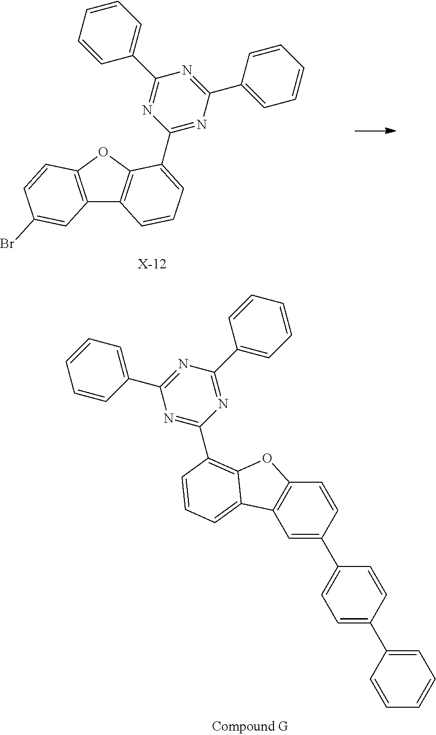
- the compound represented by Chemical Formula 1 can be prepared by appropriately substituting the starting material in accordance with the structure of the compound to be prepared with reference to Reaction Scheme 1.
- the present invention provides an organic light emitting device comprising the compound represented by Chemical Formula 1.
- the present invention provides an organic light emitting device comprising: a first electrode; a second electrode provided to face the first electrode; and one or more organic material layers provided between the first electrode and the second electrode, wherein one or more of the organic material layers comprise the compound of Chemical Formula 1.
- the organic material layer of the organic light emitting device of the present invention may have a single layer structure, or a multilayered structure in which two or more organic material layers are laminated.
- the organic light emitting device of the present invention may have a structure including a hole injection layer, a hole transport layer, a light emitting layer, an electron transport layer, an electron injection layer, and the like as the organic material layer.
- the structure of the organic light emitting device is not limited thereto, but may include a smaller number of organic layers.
- the organic material layer may include a light emitting layer, and the light emitting layer includes the compound represented by Chemical Formula 1.
- the compound represented by Chemical Formula 1 can be used as a host material in the light emitting layer.
- the organic light emitting device according to the present invention may be an organic light emitting device having a structure (normal type) where an anode, one or more organic material layers, and a cathode are sequentially laminated on a substrate.
- the organic light emitting device according to the present invention may be an organic light emitting device having an inverted direction structure (inverted type) where the cathode, one or more organic material layers, and the anode are sequentially laminated on the substrate.
- FIGS. 1 and 2 the structure of the organic light emitting device according to one embodiment of the present invention is illustrated in FIGS. 1 and 2 .
- FIG. 1 illustrates an example of an organic light emitting device including a substrate 1 , an anode 2 , a light emitting layer 3 , and a cathode 4 .
- the compound represented by Chemical Formula 1 may be included in the light emitting layer.
- FIG. 2 illustrates an example of an organic light emitting device including a substrate 1 , an anode 2 , a hole injection layer 5 , a hole transport layer 6 , a light emitting layer 7 , an electron transport layer 8 , and a cathode 4 .
- the compound represented by Chemical Formula 1 may be included in one or more layers of the hole injection layer, the hole transport layer, the light emitting layer, and the electron transport layer.
- the organic light emitting device according to the present invention may be manufactured by using materials and methods known in the art, except that one or more of organic material layers include the compound represented by Chemical Formula 1. Further, in the case where the organic light emitting device includes a plurality of organic material layers, the organic material layers may be formed of the same materials or different materials.
- the organic light emitting device may be manufactured by sequentially laminating the first electrode, the organic material layer, and the second electrode on the substrate.
- the organic light emitting device may be manufactured by depositing a metal, metal oxides having conductivity, or an alloy thereof on the substrate by using a PVD (physical vapor deposition) method such as a sputtering method or an e-beam evaporation method to form the anode, forming the organic material layer including the hole injection layer, the hole transport layer, the light emitting layer, and the electron transport layer thereon, and then depositing a material that can be used as the cathode thereon.
- the organic light emitting device may be manufactured by sequentially depositing a cathode material, the organic material layer, and an anode material on the substrate.
- the compound represented by Chemical Formula 1 may be formed as the organic material layer by a vacuum deposition method as well as a solution coating method during the production of the organic light emitting device.
- the solution coating method means spin coating, dip coating, doctor blading, inkjet printing, screen printing, a spray method, roll coating, or the like, but is not limited thereto.
- the organic light emitting device may be manufactured by sequentially depositing a cathode material, an organic material layer, and an anode material on a substrate (International Publication WO 2003/012890).
- the manufacturing method is not limited thereto.
- the first electrode is the anode
- the second electrode is the cathode
- the first electrode is the cathode
- the second electrode is the anode
- anode material generally, a material having a large work function is preferably used so that holes can be smoothly injected into the organic material layer.
- the anode material include metals such as vanadium, chrome, copper, zinc, and gold, or an alloy thereof; metal oxides such as zinc oxides, indium oxides, indium tin oxides (ITO), and indium zinc oxides (IZO); a combination of metals and oxides, such as ZnO:Al or SNO 2 :Sb; conductive polymers such as poly(3-methylthiophene), poly[3,4-(ethylene-1,2-dioxy)thiophene] (PEDOT), polypyrrole, and polyaniline, and the like, but are not limited thereto.
- the cathode material generally, a material having a small work function is preferably used so that electrons can be easily injected into the organic material layer.
- the cathode material include metals such as magnesium, calcium, sodium, potassium, titanium, indium, yttrium, lithium, gadolinium, aluminum, silver, tin, and lead, or an alloy thereof; a multilayered structure material such as LiF/Al or LiO 2 /Al, and the like, but are not limited thereto.
- the hole injection material layer is a layer injecting the holes from the electrode, and the hole injection material is preferably a compound which has an ability of transporting the holes, a hole injection effect in the anode and an excellent hole injection effect to the light emitting layer or the light emitting material, prevents movement of an exciton generated in the light emitting layer to the electron injection layer or the electron injection material, and has an excellent thin film forming ability. It is preferable that a HOMO (highest occupied molecular orbital) of the hole injection material is between the work function of the anode material and a HOMO of a peripheral organic material layer.
- the hole injection material examples include metal porphyrine, oligothiophene, an arylamine-based organic material, a hexanitrilehexaazatriphenylene-based organic material, a quinacridone-based organic material, a perylene-based organic material, anthraquinone, polyaniline and polythiophene-based conductive polymer, and the like, but are not limited thereto.
- the hole transport layer is a layer receiving the holes from the hole injection layer and transporting the holes to the light emitting layer
- the hole transport material is a material that can receive the holes from the anode or the hole injection layer and transport the holes to the light emitting layer, and a material having large mobility to the holes is suitable.
- Specific examples thereof include an arylamine-based organic material, a conductive polymer, a block copolymer in which a conjugate portion and a non-conjugate portion are present together, and the like, but are not limited thereto.
- the light emitting material layer is a material that can receive the holes and the electrons from the hole transport layer and the electron transport layer, respectively, and bond the holes and the electrons to emit light in a visible ray region, and is preferably a material having good quantum efficiency to fluorescence or phosphorescence.
- Specific examples thereof include a 8-hydroxy-quinoline aluminum complex (Alq 3 ); a carbazole-based compound; a dimerized styryl compound; BAIq; a 10-hydroxybenzoquinoline-metal compound; benzoxazole, benzthiazole, and benzimidazole-based compounds; a poly(p-phenylenevinylene) (PPV)-based polymer; a spiro compound; polyfluorene, lubrene, and the like, but are not limited thereto.
- Alq 3 8-hydroxy-quinoline aluminum complex
- a carbazole-based compound a dimerized styryl compound
- BAIq a 10-hydroxybenzoquinoline-metal compound
- benzoxazole, benzthiazole, and benzimidazole-based compounds a poly(p-phenylenevinylene) (PPV)-based polymer
- a spiro compound polyfluorene, lubrene, and the like
- the light emitting layer may include a host material and a dopant material.
- the host material include a condensation aromatic cycle derivative, a heterocycle-containing compound, or the like.
- Specific examples of the comdensation aromatic cycle derivative include an anthracene derivative, a pyrene derivative, a naphthalene derivative, a pentacene derivative, a phenanthrene compound, a fluoranthene compound, and the like
- specific examples of the heterocycle-containing compound include a carbazole derivative, a dibenzofuran derivative, a ladder-type furan compound, a pyrimidine derivative, and the like, but are not limited thereto.
- the dopant material examples include an aromatic amine derivative, a styrylamine compound, a boron complex, a fluoranthene compound, a metal complex, and the like.
- the aromatic amine derivative is a comdensation aromatic cycle derivative having a substituted or unsubstituted arylamino group, examples thereof include pyrene, anthracene, chrysene, and periflanthene having the arylamino group, and the like
- the styrylamine compound is a compound where at least one arylvinyl group is substituted in substituted or unsubstituted arylamine, in which one or two or more substituent groups selected from the group consisting of an aryl group, a silyl group, an alkyl group, a cycloalkyl group, and an arylamino group are substituted or unsubstituted.
- examples thereof include styrylamine, styryldiamine, styryltriamine, styryltetramine, and the like, but are not limited thereto.
- examples of the metal complex include an iridium complex, a platinum complex, and the like, but are not limited thereto.
- the electron transport material is a layer receiving the electrons from the electron injection layer and transporting the electrons to the light emitting layer
- the electron transport material is a material that can receive the electrons well from the cathode and transport the electrons to the light emitting layer
- a material having large mobility to the electrons is suitable.
- Specific examples thereof include an 8-hydroxyquinoline Al complex; a complex including Alq 3 ; an organic radical compound; a hydroxyflavone-metal complex, and the like, but are not limited thereto.
- the electron transport layer may be used together with a predetermined desired cathode material as used according to the prior art.
- an example of an appropriate cathode material is a general material having the low work function and followed by an aluminum layer or a silver layer.
- Specific examples thereof include cesium, barium, calcium, ytterbium, and samarium, and each case is followed by the aluminum layer or the silver layer.
- the electron injection layer is a layer injecting the electrons from the electrode, and a compound which has an ability of transporting the electrons, an electron injection effect from the cathode, and an excellent electron injection effect to the light emitting layer or the light emitting material, prevents movement of an exciton generated in the light emitting layer to the hole injection layer, and has an excellent thin film forming ability is preferable.
- fluorenone anthraquinodimethane, diphenoquinone, thiopyran dioxide, oxazole, oxadiazole, triazole, imidazole, perylene tetracarboxylic acid, fluorenylidene methane, anthrone, and the like, and derivatives thereof, a metal complex compound, a nitrogen-containing 5-membered cycle derivative, and the like, but are not limited thereto.
- Examples of the metal complex compound include 8-hydroxyquinolinato lithium, bis(8-hydroxyquinolinato)zinc, bis(8-hydroxyquinolinato)copper, bis(8-hydroxyquinolinato)manganese, tris(8-hydroxyquinolinato)aluminum, tris(2-methyl-8-hydroxyquinolinato)aluminum, tris(8-hydroxyquinolinato)gallium, bis(10-hydroxybenzo[h]quinolinato)beryllium, bis(10-hydroxybenzo[h]quinolinato)zinc, bis(2-methyl-8-quinolinato)chlorogallium, bis(2-methyl-8-quinolinato)(o-cresolato)gallium, bis(2-methyl-8-quinolinato)(1-naphtholato)aluminum, bis(2-methyl-8-quinolinato)(2-naphtholato)gallium, and the like, but are not limited thereto.
- the organic light emitting device may be a front side emission type, a back side emission type, or a double side emission type according to the used material.
- the compound represented by Chemical Formula 1 may be included in an organic solar cell or an organic transistor in addition to the organic light emitting device.
- a glass substrate on which a thin film of ITO (indium tin oxide) was coated in a thickness of 1,300 ⁇ was put into distilled water containing the detergent dissolved therein and washed by the ultrasonic wave.
- the used detergent was a product commercially available from Fisher Co. and the distilled water was one which had been twice filtered by using a filter commercially available from Millipore Co.
- the ITO was washed for 30 minutes, and washing with ultrasonic waves was then repeated twice for 10 minutes by using distilled water. After the washing with distilled water was completed, the substrate was ultrasonically washed with isopropyl alcohol, acetone, and methanol solvent, and dried, after which it was transported to a plasma cleaner. Then, the substrate was cleaned with oxygen plasma for 5 minutes, and then transferred to a vacuum evaporator.
- a compound of HI-1 as described below was thermally deposited under vacuum to a thicknesses of 50 ⁇ to form the hole injection layer.
- the compound of HT-1 was thermally deposited under vacuum to a thicknesses of 250 ⁇ to form a hole transport layer, and a compound of HT-2 was deposited under vacuum to a thickness of 50 ⁇ on the HT-1 deposition layer to form an electron blocking layer.
- the compound 1 prepared in Synthesis Example 1-1 was co-deposited with 12% by weight of a phosphorescent dopant YGD-1 to form a light emitting layer having a thickness of 400 ⁇ .
- a material of ET-1 was deposited under vacuum to a thickness of 250 ⁇ , and additionally a material of ET-2 was co-deposited with 2% by weight of Li to a thickness of 100 ⁇ to form an electron transport layer and an electron injection layer.
- Aluminum was deposited on the electron injection layer to a thickness of 1000 ⁇ to form a cathode.
- the vapor deposition rate of the organic material was maintained at 0.4 to 0.7 ⁇ /sec
- the deposition rate of aluminum was maintained at 2 ⁇ /sec
- the degree of vacuum during vapor deposition was maintained at 2 ⁇ 10 ⁇ 7 ⁇ 5 ⁇ 10 ⁇ 6 torr.
- the organic light emitting devices of Examples 2 to 49 were each fabricated in the same manner as in Example 1, except that the phosphorescent host material and the dopant content at the time of forming the light emitting layer were changed as shown in Tables 1 to 3 below.
- the organic light emitting devices of Comparative Examples 1 to 10 were each fabricated in the same manner as in Example 1, except that the phosphorescent host material and the dopant content at the time of forming the light emitting layer were changed as shown in Table 3 below.
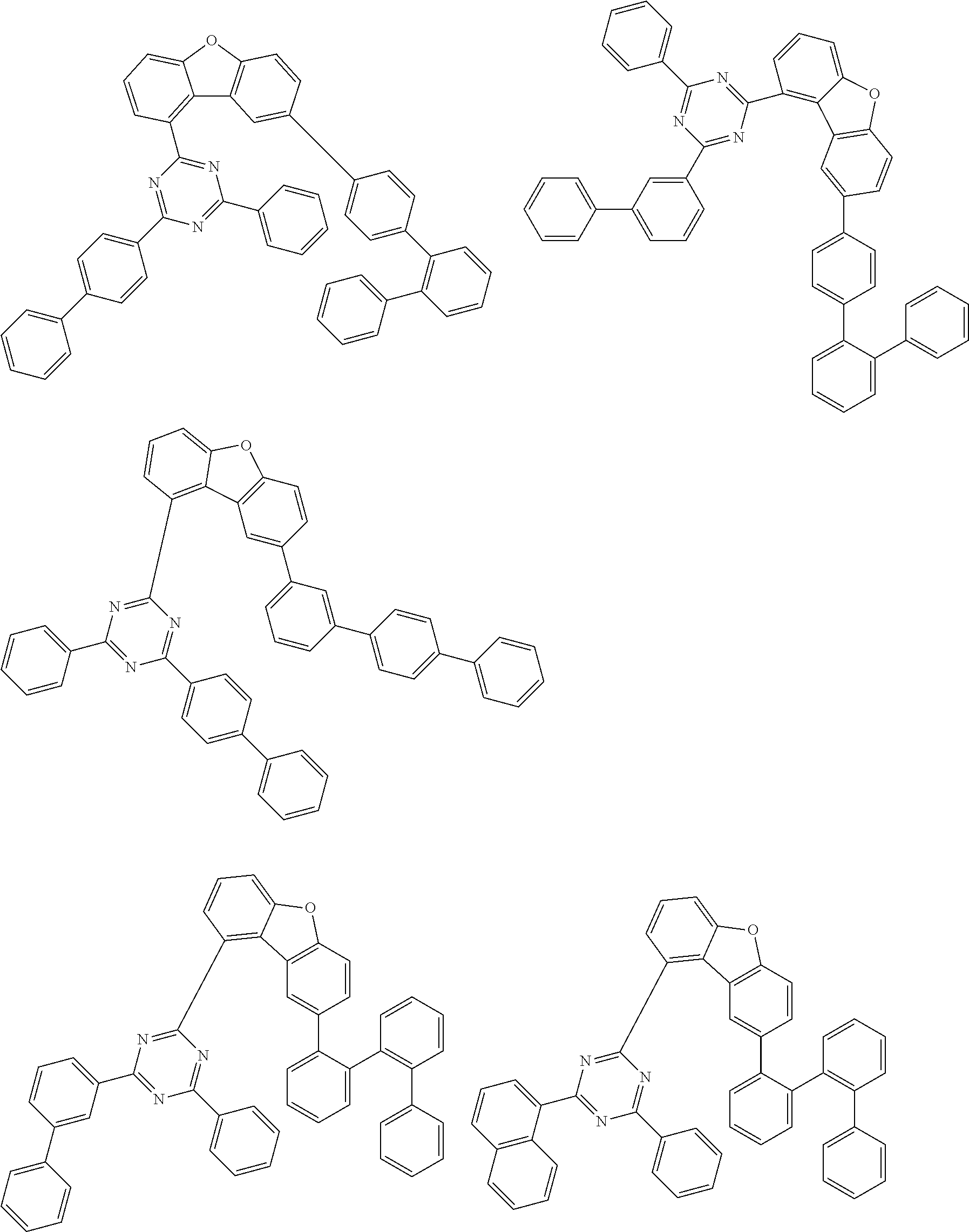
- the host materials represented by compound A to compound I used in Comparative Examples are as follows.
- T95 means the time required for the luminance to be reduced to 95% when the initial luminance at a light density of 50 mA/cm 2 was taken as 100%.
- a compound of HI-1 described below was thermally deposited under vacuum to a thicknesses of 150 ⁇ on the ITO transparent electrode prepared as in Example 1 to form the hole injection layer.
- the compound of HT-1 was thermally deposited under vacuum to a thicknesses of 1150 ⁇ , and then a compound of HT-3 was deposited under vacuum to a thickness of 500 ⁇ to form a hole transport layer.
- the compound 47 prepared in Synthesis Example 15-3 was co-deposited with 5% by weight of a phosphorescent dopant GD-1 to form a light emitting layer having a thickness of 400 ⁇ .
- a material of ET-3 was deposited under vacuum to a thickness of 50 ⁇ to form a hole blocking layer, and a material of ET-4 and LIQ were deposited under vacuum at a weight ratio of 1:1 to form an electron transport layer.
- Lithium fluoride (LiF) was sequentially deposited on the electron transport layer in a thickness of 10 ⁇ , and Mg was deposited with Ag of 10% by weight on the electron transport layer to form an electron injection layer having a thickness of 200 ⁇ .
- Aluminum was deposited thereon in a thickness of 1000 ⁇ to form a cathode.
- the vapor deposition rate of the organic material was maintained at 0.4 to 0.7 ⁇ /sec
- the lithium fluoride of the cathode was maintained at a deposition rate of 0.3 ⁇ /sec
- the deposition rate of aluminum was maintained at 2 ⁇ /sec.
- the degree of vacuum during vapor deposition was maintained at 1 ⁇ 10 ⁇ 7 ⁇ 5 ⁇ 10 ⁇ 8 torr.
- the organic light emitting devices of Examples 51 to 90 were each fabricated in the same manner as in Example 50, except that the phosphorescent host material and the dopant content at the time of forming the light emitting layer were changed as shown in Tables 4 and 5 below.
- the organic light emitting devices of Comparative Examples 11 to 19 were each fabricated in the same manner as in Example 50, except that the phosphorescent host material and the dopant content at the time of forming the light emitting layer were changed as shown in Table 6 below.
- the host materials represented by compound A to compound I used in Comparative Examples are as described above.
- T95 means the time required for the luminance to be reduced to 95% when the initial luminance at a light density of 20 mA/cm 2 was taken as 100%.
- Example compound 47 No. content (@10 mA/cm 2 ) (@10 mA/cm 2 ) (x, y) (@20 mA/cm 2 )
- Example compound 47 GD-1 4 50.8 (0.349, 0.612) 52.9 50 (400) 5%
- the organic light emitting devices fabricated using the compound according to the present invention as a phosphorescent host material exhibited excellent performance in terms of driving voltage, current efficiency, and lifetime as compared with the organic light emitting devices of Comparative Examples.
- the organic light emitting devices according to Examples showed an increase in lifetime of at least 150% as compared with the organic light emitting devices according to Comparative Examples 9 and 19 using Compound I, which is a phosphorescent host material commonly used in the art. Further, the organic light emitting devices according to Examples 4, 8 and 50 showed an increase in lifetime of about 250% as compared with the organic light emitting devices according to Comparative Examples 1, 6, 11 and 16 using Compounds A and F in which the substitution position of triazinyl group is different from that of the compound according to the present invention.
- the organic light emitting device according to Example 28 also showed an increase in lifetime of about 370% or more as compared with the organic light emitting device according to Comparative Example 3 using Compound C
- the organic light emitting device according to Examples 30 and 31 also showed an increase in lifetime of about 250% or more as compared with the organic light emitting device according to Comparative Example 7 using Compound G.
- the driving voltage, current efficiency and lifetime of the organic light emitting device according to Comparative Example 5 using the compound E containing no triazinyl group were significantly lower than those of the organic light emitting device according to Examples.
- the organic light emitting device according to Comparative Examples 8 and 18 using the compound H substituted with a dimethylfluorenyl group showed a remarkably low life time as compared with the organic light emitting device according to Examples, which is believed to be due to the generation of impurities resulting from the formation of radicals by dimethylfluorenyl in the polymer.
Landscapes
- Chemical & Material Sciences (AREA)
- Organic Chemistry (AREA)
- Engineering & Computer Science (AREA)
- Materials Engineering (AREA)
- Physics & Mathematics (AREA)
- Spectroscopy & Molecular Physics (AREA)
- Optics & Photonics (AREA)
- Electroluminescent Light Sources (AREA)
- Plural Heterocyclic Compounds (AREA)
Abstract

where X1 is O or S; L1 and L2 are each independently a single bond, a substituted or unsubstituted phenylene, a substituted or unsubstituted naphthylene, or a substituted or unsubstituted biphenylenyl; Y1 to Y3 are each independently N or CR3, provided that at least one of Y1 to Y3 is N; and Ar1a and Ar1b are each independently a substituted or unsubstituted C6-60 aryl or a substituted or unsubstituted C1-60 heteroaryl containing 1 to 3 heteroatoms selected from the group consisting of N, O and S;
and an organic light emitting device comprising the same, where the compound of Chemical Formula 1 can be used as a material of an organic material layer of an organic light emitting device and can exhibit improved efficiency, a low driving voltage and/or improved lifetime characteristics of the organic light emitting device.
Description

-
- X1 is O or S.
- L1 and L2 are each independently a single bond; a substituted or unsubstituted C6-60 arylene; or a substituted or unsubstituted C1-60 heteroarylene containing one or more heteroatoms selected from the group consisting of O, N, Si and S,
- Y1 to Y3 are each independently N or CR3, provided that at least one of Y1 to Y3 is N,
- Ar1a and Ar1b are each independently a substituted or unsubstituted C6-60 aryl; or a substituted or unsubstituted C1-60 heteroaryl containing 1 to 3 heteroatoms selected from the group consisting of N, O and S,
- Ar2 is a substituted or unsubstituted C6-60 aryl,
- R1 to R3 are each independently hydrogen; deuterium; halogen; cyano; nitro; amino; a substituted or unsubstituted C1-60 alkyl; a substituted or unsubstituted C1-60 haloalkyl; a substituted or unsubstituted C1-60 alkoxy; a substituted or unsubstituted C1-60 haloalkoxy; a substituted or unsubstituted C3-60 cycloalkyl; a substituted or unsubstituted C2-60 alkenyl; a substituted or unsubstituted C6-60 aryl; a substituted or unsubstituted C6-60 aryloxy; or a substituted or unsubstituted C1-60 heteroaryl containing at least one heteroatom selected from the group consisting of N, O and S, and
- n1 and n2 are each independently an integer of 0 to 3.
means a bond connected to another substituent group, and a single bond means when a separate atom does not exist in a portion denoted by L1 and L2.


and the like can be formed. However, the structure is not limited thereto.


-
- Y1 is N, Y2 is N, and Y3 is N; or
- Y1 is N, Y2 is N, and Y3 is CR3; or
- Y1 is N, Y2 is CR3, and Y3 is N; or
- Y1 is N, Y2 is CR3, and Y3 or CR3; or
- Y1 is CR3, Y2 is CR3, and Y3 is N.
- Preferably, in
Chemical Formula 1, - Y1 is N, Y2 is N, and Y3 is N; or
- Y1 is N, Y2 is N, and Y3 is CH; or
- Y1 is N, Y2 is CH, and Y3 is N; or
- Y1 is N, Y2 is CH, and Y3 is CH; or
- Y1 is CH, Y2 is CH, and Y3 is N.

-
- wherein,
- X2 is O, S, NZ4, or CZ5Z6,
- Z1 to Z6 are each independently hydrogen; deuterium; halogen; cyano; nitro; amino; a substituted or unsubstituted C1-20 alkyl, a substituted or unsubstituted C1-20 haloalkyl, a substituted or unsubstituted C6-20 aryl, or a substituted or unsubstituted C1-20 heteroaryl containing one or more heteroatoms selected from the group consisting of N, O and S,
- c1 is an integer of 0 to 5,
- c2 is an integer of 0 to 4, and
- c3 is an integer of 0 to 3.


-
- c11 is an integer of 0 to 5,
- c12 is an integer of 0 to 7,
- c13 is an integer of 0 to 9,
- c14 is an integer of 0 to 4,
- c15 is an integer of 0 to 3,
- c16 is an integer of 0 to 11,
- c17 is an integer of 0 to 9,
- c18 is an integer of 0 to 6, and
- c19 is an integer of 0 to 12.


| TABLE 1 | |||||
| Host:dopant | Color | Life time (T95, | |||
| (thickness, Å) dopant | Voltage (V) | Efficiency (Cd/A) | coordinate | h) | |
| No. | content | (@10 mA/cm2) | (@10 mA/cm2) | (x, y) | (@50 mA/cm2) |
| Example 1 | compound 1:YGD-1 | 2.99 | 62.8 | (0.46, 0.54) | 47.5 |
| (400) 12% | |||||
| Example 2 | compound 2:YGD-1 | 2.99 | 64.1 | (0.46, 0.53) | 50.5 |
| (400) 12% | |||||
| Example 3 | compound 3:YGD-1 | 2.97 | 65.0 | (0.46, 0.52) | 47.0 |
| (400) 16% | |||||
| Example 4 | compound 4:YGD-1 | 3.15 | 62.8 | (0.46, 0.53) | 78.6 |
| (400) 12% | |||||
| Example 5 | compound 5:YGD-1 | 3.11 | 53.8 | (0.47, 0.52) | 46.4 |
| (400) 14% | |||||
| Example 6 | compound 6:YGD-1 | 3.23 | 62.7 | (0.47, 0.53) | 49.9 |
| (400) 12% | |||||
| Example 7 | compound 7:YGD-1 | 3.20 | 63.1 | (0.46, 0.53) | 50.3 |
| (400) 12% | |||||
| Example 8 | compound 8:YGD-1 | 3.30 | 55.7 | (0.47, 0.52) | 87.9 |
| (400) 16% | |||||
| Example 9 | compound 9:YGD-1 | 2.97 | 64.2 | (0.46, 0.54) | 70.5 |
| (400) 16% | |||||
| Example | compound 10:YGD-1 | 3.12 | 60.3 | (0.47, 0.53) | 47.7 |
| 10 | (400) 16% | ||||
| Example | compound 11:YGD-1 | 2.89 | 63.0 | (0.46, 0.53) | 69.8 |
| 11 | (400) 16% | ||||
| Example | compound 14:YGD-1 | 3.08 | 56.1 | (0.45, 0.54) | 47.6 |
| 12 | (400) 16% | ||||
| Example | compound 15:YGD-1 | 3.00 | 63.0 | (0.46, 0.53) | 47.1 |
| 13 | (400) 12% | ||||
| Example | compound 16:YGD-1 | 3.28 | 63.2 | (0.46, 0.53) | 41.8 |
| 14 | (400) 12% | ||||
| Example | compound 12:YGD-1 | 3.55 | 65.9 | (0.46, 0.52) | 126.2 |
| 15 | (200:200) 16% | ||||
| Example | compound 13:PH- | 3.51 | 67.2 | (0.46, 0.53) | 116.0 |
| 16 | 1:YGD-1 | ||||
| (160:240) 16% | |||||
| Example | compound 4:PH- | 3.57 | 67.7 | (0.46, 0.53) | 191.9 |
| 17 | 2:YGD-1 | ||||
| (160:240) 12% | |||||
| Example | compound 17:PH- | 3.53 | 67.8 | (0.47, 0.53) | 125.1 |
| 18 | 2:YGD-1 | ||||
| (200:200) 16% | |||||
| Example | compound 18:PH- | 3.56 | 70.2 | (0.45, 0.53) | 132.8 |
| 19 | 2:YGD-1 | ||||
| (160:240) 12% | |||||
| Example | compound 19:PH- | 3.50 | 68.9 | (0.46, 0.53) | 352.0 |
| 20 | 2:YGD-1 | ||||
| (200:200) 15% | |||||
| TABLE 2 | |||||
| Host:dopant | Efficiency | Color | Life time (T95, | ||
| (thickness, Å) dopant | Voltage (V) | (Cd/A) | coordinate | h) | |
| No. | content | (@10 mA/cm2) | (@10 mA/cm2) | (x, y) | (@50 mA/cm2) |
| Example | compound 20:PH- | 3.64 | 65.4 | (0.45, 0.54) | 155.7 |
| 21 | 3:YGD-1 | ||||
| (160:240) 12% | |||||
| Example | compound 21:PH- | 3.58 | 64.1 | (0.46, 0.54) | 100.3 |
| 22 | 2:YGD-1 | ||||
| (200:200) 14% | |||||
| Example | compound 22:PH- | 3.60 | 66.5 | (0.46, 0.54) | 115.6 |
| 23 | 3:YGD-1 | ||||
| (200:200) 16% | |||||
| Example | compound 23:PH- | 3.71 | 66.8 | (0.46, 0.53) | 180.3 |
| 24 | 2:YGD-1 | ||||
| (160:240) 12% | |||||
| Example | compound 24:PH- | 3.48 | 67.1 | (0.46, 0.53) | 230.7 |
| 25 | 2:YGD-1 | ||||
| (160:240) 12% | |||||
| Example | compound 25:YGD-1 | 3.12 | 60.3 | (0.46, 0.52) | 48.3 |
| 26 | (400) 16% | ||||
| Example | compound 26:YGD-1 | 3.01 | 61.7 | (0.48, 0.51) | 84.9 |
| 27 | (400) 12% | ||||
| Example | compound 27:YGD-1 | 2.98 | 58.5 | (0.48, 0.51) | 76.1 |
| 28 | (400) 16% | ||||
| Example | compound 28:YGD-1 | 3.00 | 67.1 | (0.47, 0.52) | 87.2 |
| 29 | (400) 16% | ||||
| Example | compound 29:YGD-1 | 3.04 | 65.4 | (0.46, 0.53) | 68.1 |
| 30 | (400) 16% | ||||
| Example | compound 30:YGD-1 | 3.01 | 66.1 | (0.46, 0.52) | 73.6 |
| 31 | (400) 16% | ||||
| Example | compound 31:YGD-1 | 3.12 | 60.2 | (0.46, 0.53) | 77.2 |
| 32 | (400) 12% | ||||
| Example | compound 32:YGD-1 | 3.08 | 64.2 | (0.45, 0.53) | 76.8 |
| 33 | (400) 12% | ||||
| Example | compound 33:YGD-1 | 3.11 | 52.6 | (0.45, 0.53) | 46.2 |
| 34 | (400) 16% | ||||
| Example | compound 34:YGD-1 | 2.97 | 59.9 | (0.46, 0.54) | 74.3 |
| 35 | (400) 16% | ||||
| Example | compound 35:YGD-1 | 3.04 | 62.4 | (0.45, 0.53) | 79.8 |
| 36 | (400) 12% | ||||
| Example | compound 36:YGD-1 | 3.10 | 59.15 | (0.45, 0.55) | 48.4 |
| 37 | (400) 16% | ||||
| Example | compound 37:YGD-1 | 3.01 | 59.2 | (0.45, 0.53) | 44.1 |
| 38 | (400) 14% | ||||
| Example | compound 38:PH- | 3.52 | 67.2 | (0.46, 0.53) | 160.3 |
| 39 | 1:YGD-1 | ||||
| (200:200) 12% | |||||
| Example | compound 39:PH- | 3.49 | 72.4 | (0.45, 0.54) | 265.8 |
| 40 | 2:YGD-1 | ||||
| (160:240) 16% | |||||
| TABLE 3 | |||||
| Host:dopant | Efficiency | Color | Life time (T95, | ||
| (thickness, Å) dopant | Voltage (V) | (Cd/A) | coordinate | h) | |
| No. | content | (@10 mA/cm2) | (@10 mA/cm2) | (x, y) | (@50 mA/cm2) |
| Example | compound 40:PH- | 3.61 | 62.6 | (0.44, 0.54) | 102.8 |
| 41 | 3:YGD-1 | ||||
| (200:200) 16% | |||||
| Example | compound 41:PH- | 3.48 | 65.1 | (0.47, 0.53) | 272.1 |
| 42 | 2:YGD-1 | ||||
| (160:240) 16% | |||||
| Example | compound 42:PH- | 3.52 | 67.7 | (0.45, 0.54) | 326.1 |
| 43 | 2:YGD-1 | ||||
| (160:240) 12% | |||||
| Example | compound 43:PH- | 3.55 | 62.4 | (0.45, 0.53) | 239.8 |
| 44 | 3:YGD-1 | ||||
| (160:240) 12% | |||||
| Example | compound 44:PH- | 3.60 | 60.0 | (0.46, 0.52) | 154.2 |
| 45 | 3:YGD-1 | ||||
| (200:200) 16% | |||||
| Example | compound 46:PH- | 3.62 | 64.68 | (0.45, 0.53) | 175.3 |
| 46 | 1:YGD-1 | ||||
| (160:240) 16% | |||||
| Example | compound 28:PH- | 3.51 | 67.9 | (0.45, 0.54) | 330.2 |
| 47 | 2:YGD-1 | ||||
| (160:240) 16% | |||||
| Example | compound 81 PH- | 3.53 | 65.3 | (0.47, 0.54) | 289.6 |
| 48 | 2:YGD-1 | ||||
| (160:240) 12% | |||||
| Example | compound 45:PH- | 3.50 | 68.1 | (0.45, 0.52) | 349.8 |
| 49 | 2:YGD-1 | ||||
| (160:240) 12% | |||||
| Comparative | compound A:YGD-1 | 3.21 | 61.9 | (0.46, 0.53) | 25.9 |
| Example 1 | (400) 12% | ||||
| Comparative | compound B:YGD-1 | 3.17 | 56.2 | (0.47, 0.52) | 27.3 |
| Example 2 | (400) 12% | ||||
| Comparative | compound C:YGD-1 | 2.92 | 62.2 | (0.48, 0.50) | 20.3 |
| Example 3 | (400) 12% | ||||
| Comparative | compound D:YGD-1 | 3.11 | 67.3 | (0.48, 0.53) | 26.2 |
| Example 4 | (400) 12% | ||||
| Comparative | compound E:YGD-1 | 4.73 | 28.11 | (0.47, 0.51) | 22.2 |
| Example 5 | (400) 12% | ||||
| Comparative | compound F:YGD-1 | 3.15 | 53.2 | (0.48, 0.50) | 27.5 |
| Example 6 | (400) 12% | ||||
| Comparative | compound G:YGD-1 | 3.14 | 52.7 | (0.49, 0.50) | 26.9 |
| Example 7 | (400) 12% | ||||
| Comparative | compound H:YGD-1 | 3.14 | 56.8 | (0.49, 0.50) | 28.9 |
| Example 8 | (400) 12% | ||||
| Comparative | compound I:YGD-1 | 3.0 | 60 | (0.46, 0.53) | 31.5 |
| Example 9 | (400) 12% | ||||
| Comparative | compound A:PH- | 3.63 | 64.3 | (0.47, 0.53) | 63.2 |
| Example | 1:YGD-1 | ||||
| 10 | (160:240) 16% | ||||

| TABLE 4 | |||||
| Host:dopant | Color | Life time (T95, | |||
| (thickness, Å) dopant | Voltage (V) | Efficiency (Cd/A) | coordinate | h) | |
| No. | content | (@10 mA/cm2) | (@10 mA/cm2) | (x, y) | (@20 mA/cm2) |
| Example | compound 47:GD-1 | 4 | 50.8 | (0.349, 0.612) | 52.9 |
| 50 | (400) 5% | ||||
| Example | compound 48:GD-1 | 4.01 | 51.1 | (0.350, 0.610) | 66.4 |
| 51 | (400) 5% | ||||
| Example | compound 49:GD-1 | 3.98 | 51.2 | (0.350, 0.611) | 59.65 |
| 52 | (400) 7% | ||||
| Example | compound 50:GD-1 | 4.11 | 51.8 | (0.348, 0.612) | 51.8 |
| 53 | (400) 5% | ||||
| Example | compound 51:GD-1 | 4.09 | 50.2 | (0.345, 0.612) | 51.4 |
| 54 | (400) 5% | ||||
| Example | compound 52:GD-1 | 4.1 | 50.8 | (0.348.0.610) | 51.5 |
| 55 | (400) 7% | ||||
| Example | compound 16:GD-1 | 4.08 | 49.1 | (0.349, 0.610) | 46.7 |
| 56 | (400) 5% | ||||
| Example | compound 53:GD-1 | 4.02 | 51.8 | (0.348, 0.612) | 55.5 |
| 57 | (400) 7% | ||||
| Example | compound 20:GD-1 | 3.97 | 52.8 | (0.349, 0.611) | 67.7 |
| 58 | (400) 5% | ||||
| Example | compound 54:GD-1 | 4.01 | 52.4 | (0.350, 0.613) | 66.2 |
| 59 | (400) 5% | ||||
| Example | compound 46:GD-1 | 4.0 | 52.9 | (0.349, 0.612) | 65.6 |
| 60 | (400) 5% | ||||
| Example | compound 55:GD-1 | 3.99 | 52.7 | (0.350, 0.611) | 65.8 |
| 61 | (400) 5% | ||||
| Example | compound 56:GD-1 | 3.99 | 52.4 | (0.347, 0.612) | 51.3 |
| 62 | (400) 10% | ||||
| Example | compound 4:PH-2:GD-1 | 3.71 | 55.1 | (0.351, 0.609) | 110.2 |
| 63 | (200:200) 5% | ||||
| Example | compound 57:PH- | 4.07 | 52.9 | (0.348, 0.612) | 79.9 |
| 64 | 3:GD-1 | ||||
| (200:200) 5% | |||||
| Example | compound 58:PH- | 4.2 | 51.7 | (0.347, 0.610) | 88.7 |
| 65 | 1:GD-1 | ||||
| (200:200) 5% | |||||
| Example | compound 6:PH-2:GD-1 | 4.21 | 53.4 | (0.347, 0.613) | 100.1 |
| 66 | (200:200) 5% | ||||
| Example | compound 50:PH- | 4.17 | 58.1 | (0.348, 0.612) | 78.9 |
| 67 | 2:GD-1 | ||||
| (160:240) 7% | |||||
| Example | compound 60:PH- | 4.23 | 51.7 | (0.347, 0.611) | 89.2 |
| 68 | 2:GD-1 | ||||
| (160:240) 5% | |||||
| Example | compound 61:PH- | 4.11 | 54.2 | (0.351, 0.613) | 106.2 |
| 69 | 3:GD-1 | ||||
| (200:200) 5% | |||||
| Example | compound 62:PH- | 4.22 | 51.9 | (0.351, 0.613) | 170.7 |
| 70 | 2:GD-1 | ||||
| (160:240) 5% | |||||
| TABLE 5 | |||||
| Host:dopant | Efficiency | Color | Life time (T95, | ||
| (thickness, Å) dopant | Voltage (V) | (Cd/A) | coordinate | h) | |
| No. | content | (@10 mA/cm2) | (@10 mA/cm2) | (x, y) | (@20 mA/cm2) |
| Example | compound 63:PH- | 4.31 | 54.2 | (0.349, 0.613) | 134.9 |
| 71 | 3:GD-1 | ||||
| (200:200) 5% | |||||
| Example | compound 64:PH- | 4.30 | 54.3 | (0.347, 0.612) | 135.4 |
| 72 | 1:GD-1 | ||||
| (160:240) 7% | |||||
| Example | compound 65:PH- | 4.19 | 52.9 | (0.351, 0.613) | 170.9 |
| 73 | 2:GD-1 | ||||
| (200:200) 5% | |||||
| Example | compound 66:PH- | 3.92 | 52.3 | (0.351, 0.613) | 171.4 |
| 74 | 1:GD-1 | ||||
| (160:240) 10% | |||||
| Example | compound 67:PH- | 4.12 | 54.9 | (0.350, 0.611) | 128.2 |
| 75 | 2:GD-1 | ||||
| (200:200) 5% | |||||
| Example | compound 68:PH- | 3.76 | 56.8 | (0.352, 0.609) | 104 |
| 76 | 1:GD-1 | ||||
| (160:240) 5% | |||||
| Example | compound 69:PH- | 4.10 | 55.1 | (0.351, 0.613) | 103.2 |
| 77 | 2:GD-1 | ||||
| (160:240) 7% | |||||
| Example | compound 70:PH- | 4.17 | 56.53 | (0.351, 0.613) | 104.5 |
| 78 | 1:GD-1 | ||||
| (160:240) 5% | |||||
| Example | compound 71:PH- | 4.24 | 54.6 | (0.346, 0.612) | 137.9 |
| 79 | 3:GD-1 | ||||
| (200:200) 7% | |||||
| Example | compound 72:PH- | 4.32 | 56.1 | (0.350, 0.612) | 158.8 |
| 80 | 2:GD-1 | ||||
| (200:200) 5% | |||||
| Example | compound 73:PH- | 4.42 | 51.24 | (0.346, 0.611) | 102.5 |
| 81 | 2:GD-1 | ||||
| (160:240) 5% | |||||
| Example | compound 74:PH- | 4.13 | 54.7 | (0.350, 0.611) | 119.9 |
| 82 | 2:GD-1 | ||||
| (160:240) 10% | |||||
| Example | compound 75:PH- | 4.43 | 50.35 | (0.346, 0.613) | 95.2 |
| 83 | 3:GD-1 | ||||
| (200:200) 7% | |||||
| Example | compound 76:PH- | 4.14 | 52.8 | (0.346, 0.612) | 105.7 |
| 84 | 3:GD-1 | ||||
| (160:240) 10% | |||||
| Example | compound 77:PH- | 4.35 | 56.4 | (0.347, 0.611) | 62.9 |
| 85 | 1:GD-1 | ||||
| (200:200) 5% | |||||
| Example | compound 78:PH- | 3.92 | 54 | (0.352, 0.609) | 81.2 |
| 86 | 1:GD-1 | ||||
| (200:200) 5% | |||||
| Example | compound 79:PH- | 4.16 | 56.13 | (0.351, 0.613) | 104.3 |
| 87 | 3:GD-1 | ||||
| (160:240) 5% | |||||
| Example | compound 80:PH- | 4.32 | 50.89 | (0.346, 0.611) | 100.4 |
| 88 | 1:GD-1 | ||||
| (160:240) 5% | |||||
| Example | compound 59:PH- | 4.29 | 53.7 | (0.347, 0.614) | 92.6 |
| 89 | 1:GD-1 | ||||
| (160:240) 6% | |||||
| Example | compound 45:PH- | 4.31 | 57.3 | (0.350, 0.611) | 168.1 |
| 90 | 1:GD-1 | ||||
| (160:240) 7% | |||||
| TABLE 6 | |||||
| Host:dopant | Efficiency | Color | Life time (T95, | ||
| (thickness, Å) dopant | Voltage (V) | (Cd/A) | coordinate | h) | |
| No. | content | (@10 mA/cm2) | (@10 mA/cm2) | (x, y) | (@20 mA/cm2) |
| Comparative | compound A:GD-1 | 4.18 | 51.2 | (0.351, 0.609) | 18.3 |
| Example | (400) 5% | ||||
| 11 | |||||
| Comparative | compound B:GD-1 | 4.16 | 46.1 | (0.352, 0.611) | 23.1 |
| Example | (400) 5% | ||||
| 12 | |||||
| Comparative | compound C:GD-1 | 4.10 | 61.8 | (0.351, 0.610) | 16.3 |
| Example | (400) 5% | ||||
| 13 | |||||
| Comparative | compound D:GD-1 | 4.21 | 62.4 | (0.351, 0.609) | 19.8 |
| Example | (400) 5% | ||||
| 14 | |||||
| Comparative | compound E:GD-1 | 5.80 | 37.1 | (0.350, 0.611) | 14.7 |
| Example | (400) 5% | ||||
| 15 | |||||
| Comparative | compound F:GD-1 | 4.08 | 44.0 | (0.352, 0.609) | 22.8 |
| Example | (400) 5% | ||||
| 16 | |||||
| Comparative | compound G:GD-1 | 4.09 | 43.2 | (0.352, 0.609) | 22.0 |
| Example | (400) 5% | ||||
| 17 | |||||
| Comparative | compound H:GD-1 | 4.19 | 51.0 | (0.352, 0.610) | 27.1 |
| Example | (400) 5% | ||||
| 18 | |||||
| Comparative | compound I:GD-1 | 4.1 | 47 | (0.349, 0.611) | 32.2 |
| Example | (400) 5% | ||||
| 19 | |||||
| [Explanation of Sign] |
| 1: substrate | 2: anode | ||
| 3: light emitting layer | 4: cathode | ||
| 5: hole injection layer | 6: hole transport layer | ||
| 7: light emitting layer | 8: electron transport layer | ||
Claims (4)


Applications Claiming Priority (5)
| Application Number | Priority Date | Filing Date | Title |
|---|---|---|---|
| KR20160092202 | 2016-07-20 | ||
| KR10-2016-0092202 | 2016-07-20 | ||
| KR1020170075029A KR101849747B1 (en) | 2016-07-20 | 2017-06-14 | Novel hetero-cyclic compound and organic light emitting device comprising the same |
| KR10-2017-0075029 | 2017-06-14 | ||
| PCT/KR2017/006274 WO2018016742A1 (en) | 2016-07-20 | 2017-06-15 | Novel heterocyclic compound and organic light-emitting device using same |
Related Parent Applications (1)
| Application Number | Title | Priority Date | Filing Date |
|---|---|---|---|
| PCT/KR2017/006274 A-371-Of-International WO2018016742A1 (en) | 2016-07-20 | 2017-06-15 | Novel heterocyclic compound and organic light-emitting device using same |
Related Child Applications (1)
| Application Number | Title | Priority Date | Filing Date |
|---|---|---|---|
| US17/842,520 Continuation US12167689B2 (en) | 2016-07-20 | 2022-06-16 | Heterocyclic compound and organic light emitting device comprising the same |
Publications (2)
| Publication Number | Publication Date |
|---|---|
| US20180337348A1 US20180337348A1 (en) | 2018-11-22 |
| US11903311B2 true US11903311B2 (en) | 2024-02-13 |
Family
ID=61070679
Family Applications (2)
| Application Number | Title | Priority Date | Filing Date |
|---|---|---|---|
| US15/771,066 Active 2038-02-01 US11903311B2 (en) | 2016-07-20 | 2017-06-15 | Heterocyclic compound and organic light emitting device comprising the same |
| US17/842,520 Active US12167689B2 (en) | 2016-07-20 | 2022-06-16 | Heterocyclic compound and organic light emitting device comprising the same |
Family Applications After (1)
| Application Number | Title | Priority Date | Filing Date |
|---|---|---|---|
| US17/842,520 Active US12167689B2 (en) | 2016-07-20 | 2022-06-16 | Heterocyclic compound and organic light emitting device comprising the same |
Country Status (6)
| Country | Link |
|---|---|
| US (2) | US11903311B2 (en) |
| EP (1) | EP3480194B1 (en) |
| JP (2) | JP7210856B2 (en) |
| KR (1) | KR101849747B1 (en) |
| CN (1) | CN108368078B (en) |
| TW (1) | TWI653233B (en) |
Families Citing this family (67)
| Publication number | Priority date | Publication date | Assignee | Title |
|---|---|---|---|---|
| KR101849747B1 (en) | 2016-07-20 | 2018-05-31 | 주식회사 엘지화학 | Novel hetero-cyclic compound and organic light emitting device comprising the same |
| CN109415354B (en) * | 2016-08-19 | 2023-11-14 | 九州有机光材股份有限公司 | Charge transport materials, compounds, delayed fluorescent materials and organic light-emitting elements |
| KR102003351B1 (en) * | 2017-01-20 | 2019-07-23 | 주식회사 엘지화학 | Novel hetero-cyclic compound and organic light emitting device comprising the same |
| KR102232510B1 (en) * | 2017-05-26 | 2021-03-26 | 삼성에스디아이 주식회사 | Composition for phosphorescent host, organic optoelectronic device and display device |
| KR102107085B1 (en) * | 2017-07-14 | 2020-05-06 | 주식회사 엘지화학 | Organic light emitting device |
| KR102418440B1 (en) | 2017-09-29 | 2022-07-07 | 덕산네오룩스 주식회사 | Compound for organic electronic element, organic electronic element using the same, and an electronic device thereof |
| WO2019066242A1 (en) * | 2017-09-29 | 2019-04-04 | 덕산네오룩스 주식회사 | Compound for organic electronic element, organic electronic element using same, and electronic device comprising same |
| CN108424420B (en) * | 2017-09-30 | 2021-01-12 | 北京绿人科技有限责任公司 | Triazine compound containing silicon atom, application thereof and organic electroluminescent device |
| KR102134383B1 (en) * | 2017-12-12 | 2020-07-15 | 주식회사 엘지화학 | Organic light emitting device |
| KR102154083B1 (en) * | 2017-12-29 | 2020-09-09 | 삼성에스디아이 주식회사 | Compound for organic optoelectronic device, composition for organic optoelectronic device, organic optoelectronic device and display device |
| JP7551273B2 (en) * | 2018-01-11 | 2024-09-17 | 三星電子株式会社 | Compound, material for organic electroluminescence device, composition for organic electroluminescence device, and organic electroluminescence device |
| US11706977B2 (en) * | 2018-01-11 | 2023-07-18 | Samsung Electronics Co., Ltd. | Heterocyclic compound, composition including the same, and organic light-emitting device including the heterocyclic compound |
| KR102125962B1 (en) * | 2018-01-17 | 2020-06-23 | 주식회사 엘지화학 | Novel compound and organic light emitting device comprising the same |
| KR101857632B1 (en) * | 2018-02-02 | 2018-05-14 | 덕산네오룩스 주식회사 | Compound for organic electronic element, organic electronic element using the same, and an electronic device thereof |
| US12058930B2 (en) | 2018-02-20 | 2024-08-06 | Idemitsu Kosan Co., Ltd. | Organic electroluminescence device and electronic apparatus |
| WO2019163826A1 (en) * | 2018-02-20 | 2019-08-29 | 出光興産株式会社 | Novel compound and organic electroluminescence element using same |
| US11370782B2 (en) | 2018-03-06 | 2022-06-28 | Lg Chem, Ltd. | Compound and organic light emitting device comprising the same |
| KR102720177B1 (en) * | 2018-03-29 | 2024-10-21 | 덕산네오룩스 주식회사 | Compound for organic electronic element, organic electronic element using the same, and an electronic device thereof |
| US12063855B2 (en) | 2018-03-29 | 2024-08-13 | Duk San Neolux Co., Ltd. | Compound for organic electric element, organic electric element using the same, and electronic device therefor |
| CN116332916B (en) * | 2018-03-29 | 2025-08-29 | 德山新勒克斯有限公司 | Compound for organic electric element, organic electric element using the same, and electronic device thereof |
| WO2019209031A1 (en) * | 2018-04-24 | 2019-10-31 | 주식회사 엘지화학 | Novel heterocyclic compound and organic light emitting device using same |
| KR102206482B1 (en) * | 2018-04-24 | 2021-01-22 | 주식회사 엘지화학 | Novel hetero-cyclic compound and organic light emitting device comprising the same |
| EP3763720B1 (en) | 2018-04-25 | 2023-11-22 | Lg Chem, Ltd. | Compound and organic light emitting device comprising same |
| KR20190127272A (en) * | 2018-05-04 | 2019-11-13 | 덕산네오룩스 주식회사 | Compound for organic electronic element, organic electronic element using the same, and an electronic device thereof |
| KR102232407B1 (en) * | 2018-05-29 | 2021-03-26 | 주식회사 엘지화학 | Hetero compound and organic light emitting device comprising the same |
| KR102202765B1 (en) * | 2018-06-05 | 2021-01-14 | 주식회사 엘지화학 | Compound and organic light emitting device comprising same |
| KR102217250B1 (en) * | 2018-06-12 | 2021-02-18 | 삼성에스디아이 주식회사 | Composition for organic optoelectronic device and organic optoelectronic device and display device |
| KR102288989B1 (en) | 2018-08-22 | 2021-08-11 | 주식회사 엘지화학 | Novel compound and organic light emitting device comprising the same |
| KR102701149B1 (en) | 2018-09-07 | 2024-09-03 | 삼성디스플레이 주식회사 | Organic electroluminescence device and fused polycyclic compound for organic electroluminescence device |
| KR102611314B1 (en) * | 2018-09-11 | 2023-12-07 | 솔루스첨단소재 주식회사 | Organic compound and organic electroluminescent device using the same |
| KR102495276B1 (en) * | 2018-11-07 | 2023-02-01 | 삼성에스디아이 주식회사 | Organic optoelectronic device and display device |
| KR102638577B1 (en) | 2018-11-15 | 2024-02-20 | 덕산네오룩스 주식회사 | Compound for organic electronic element, organic electronic element using the same, and an electronic device thereof |
| CN111909213B (en) * | 2019-05-09 | 2024-02-27 | 北京夏禾科技有限公司 | A metal complex containing three different ligands |
| CN110156777A (en) * | 2019-05-21 | 2019-08-23 | 吉林工程技术师范学院 | A kind of triazine derivative and its organic electroluminescent device |
| CN110256412B (en) * | 2019-06-27 | 2022-04-05 | 武汉天马微电子有限公司 | A compound, organic electroluminescent device and display device |
| KR102429537B1 (en) | 2019-06-28 | 2022-08-03 | 삼성에스디아이 주식회사 | Compound for organic optoelectronic device, composition for organic optoelectronic device, organic optoelectronic device and display device |
| WO2021033724A1 (en) | 2019-08-19 | 2021-02-25 | 出光興産株式会社 | Compound, material for organic electroluminescent element, organic electroluminescent element, and electronic device |
| WO2021037401A1 (en) | 2019-08-26 | 2021-03-04 | Merck Patent Gmbh | Materials for organic electroluminescent devices |
| CN112679548B (en) | 2019-10-18 | 2023-07-28 | 北京夏禾科技有限公司 | Organic light-emitting materials with auxiliary ligands of partially fluorine-substituted substituents |
| TW202130783A (en) | 2019-11-04 | 2021-08-16 | 德商麥克專利有限公司 | Organic electroluminescent device |
| TW202136471A (en) * | 2019-12-17 | 2021-10-01 | 德商麥克專利有限公司 | Materials for organic electroluminescent devices |
| CN118084980A (en) | 2020-01-10 | 2024-05-28 | 北京夏禾科技有限公司 | Organic light-emitting materials |
| CN113121609B (en) | 2020-01-16 | 2024-03-29 | 北京夏禾科技有限公司 | Metal complex, electroluminescent device comprising same and application of metal complex |
| WO2021182833A1 (en) * | 2020-03-09 | 2021-09-16 | 주식회사 엘지화학 | Novel compound and organic light-emitting device using same |
| EP4118695B1 (en) | 2020-03-11 | 2024-05-01 | Merck Patent GmbH | Organic electroluminescent apparatus |
| WO2021182893A1 (en) * | 2020-03-11 | 2021-09-16 | 주식회사 엘지화학 | Organic light emitting device |
| KR102787035B1 (en) * | 2020-09-09 | 2025-03-25 | 삼성에스디아이 주식회사 | Compound for organic optoelectronic device, composition for organic optoelectronic device, organic optoelectronic device and display device |
| CN114599647B (en) * | 2020-09-28 | 2024-10-18 | Lt素材株式会社 | Heterocyclic compound, organic light-emitting component comprising same, and composition for organic material layer of organic light-emitting component |
| US20230354706A1 (en) * | 2020-10-22 | 2023-11-02 | Lg Chem, Ltd. | Organic light emitting device |
| CN114621198B (en) * | 2020-12-11 | 2025-01-21 | 北京夏禾科技有限公司 | Organic electroluminescent materials and devices |
| CN114695802B (en) * | 2020-12-30 | 2024-11-01 | 北京夏禾科技有限公司 | Organic electroluminescent devices |
| CN114835686B (en) * | 2021-02-02 | 2024-10-11 | 江苏三月科技股份有限公司 | Compound containing phenanthrene and triazine structure and application thereof |
| US12583814B2 (en) | 2021-02-16 | 2026-03-24 | Lg Chem, Ltd. | Compound and organic light emitting device comprising the same |
| US20240107884A1 (en) * | 2021-02-19 | 2024-03-28 | Lg Chem, Ltd. | Organic light emitting device |
| CN115148914B (en) * | 2021-03-30 | 2025-02-25 | 北京夏禾科技有限公司 | An electroluminescent device |
| US20240138256A1 (en) * | 2021-04-05 | 2024-04-25 | Lg Chem, Ltd. | Organic light emitting device |
| JP7537072B2 (en) * | 2021-04-05 | 2024-08-21 | エルジー・ケム・リミテッド | Organic light-emitting device |
| KR102623895B1 (en) * | 2021-04-27 | 2024-01-11 | 주식회사 엘지화학 | Organic light emitting device |
| CN113549059B (en) * | 2021-06-18 | 2023-04-28 | 陕西莱特光电材料股份有限公司 | Organic compound, and electronic device and electronic apparatus including the same |
| KR20230013465A (en) * | 2021-07-19 | 2023-01-26 | 주식회사 엘지화학 | Novel compound and organic light emitting device comprising the same |
| KR102746268B1 (en) * | 2021-12-03 | 2024-12-26 | 엘티소재주식회사 | Heterocyclic compound, organic light emitting device comprising same and composition for organic layer of organic light emitting device |
| CN114213373B (en) * | 2021-12-17 | 2023-06-16 | 江苏广域化学有限公司 | Synthesis method of dibenzofuran derivative |
| WO2023121071A1 (en) * | 2021-12-22 | 2023-06-29 | 주식회사 엘지화학 | Novel compound and organic light-emitting device using same |
| CN117751109A (en) * | 2021-12-22 | 2024-03-22 | 株式会社Lg化学 | Novel compound and organic light emitting device comprising the same |
| CN116751177B (en) * | 2022-03-03 | 2025-12-16 | 阜阳欣奕华新材料科技股份有限公司 | Anthracene compound, intermediate, anthracene mixture, organic electroluminescent device and display device |
| CN117682998A (en) * | 2022-08-30 | 2024-03-12 | 吉林奥来德光电材料股份有限公司 | Electron transmission material and preparation method thereof, light-emitting device |
| WO2025143781A1 (en) * | 2023-12-27 | 2025-07-03 | 솔루스첨단소재 주식회사 | Organic compound and organic electroluminescent device comprising same |
Citations (35)
| Publication number | Priority date | Publication date | Assignee | Title |
|---|---|---|---|---|
| KR20000051826A (en) | 1999-01-27 | 2000-08-16 | 성재갑 | New organomattalic complex molecule for the fabrication of organic light emitting diodes |
| WO2003012890A2 (en) | 2001-07-20 | 2003-02-13 | Novaled Gmbh | Light emitting component with organic layers |
| US20060088728A1 (en) * | 2004-10-22 | 2006-04-27 | Raymond Kwong | Arylcarbazoles as hosts in PHOLEDs |
| US20120235123A1 (en) | 2009-08-10 | 2012-09-20 | Rohm And Haas Electronic Materials Korea Ltd. | Novel organic electroluminescent compounds and organic electroluminescent device using the same |
| US8367850B2 (en) | 2007-08-08 | 2013-02-05 | Universal Display Corporation | Benzo-fused thiophene or benzo-fused furan compounds comprising a triphenylene group |
| KR20150031396A (en) | 2013-09-13 | 2015-03-24 | (주)씨에스엘쏠라 | New organic electroluminescent compounds and organic electroluminescent device comprising the same |
| US20150171340A1 (en) * | 2013-12-17 | 2015-06-18 | Samsung Electronics Co., Ltd. | Condensed cyclic compound and organic light-emitting device including the same |
| KR20150074603A (en) | 2013-12-24 | 2015-07-02 | 희성소재 (주) | Fluorene-based compound and organic light emitting device using the same |
| WO2015105251A1 (en) | 2014-01-09 | 2015-07-16 | 삼성에스디아이 주식회사 | Organic compound, organic optoelectronic device, and display device |
| US20150228908A1 (en) | 2014-02-11 | 2015-08-13 | Samsung Electronics Co., Ltd. | Carbazole-based compound and organic light-emitting device including the same |
| WO2015169412A1 (en) | 2014-05-05 | 2015-11-12 | Merck Patent Gmbh | Materials for organic light emitting devices |
| US9190620B2 (en) | 2014-03-01 | 2015-11-17 | Universal Display Corporation | Organic electroluminescent materials and devices |
| US20150349268A1 (en) | 2014-05-27 | 2015-12-03 | Universal Display Corporation | Organic Electroluminescent Materials and Devices |
| KR20150136027A (en) | 2014-05-26 | 2015-12-04 | 주식회사 엘지화학 | Hetero-cyclic compound and organic light emitting device comprising the same |
| JP5831654B1 (en) * | 2015-02-13 | 2015-12-09 | コニカミノルタ株式会社 | Aromatic heterocycle derivative, organic electroluminescence device using the same, illumination device and display device |
| KR20160006633A (en) | 2014-07-09 | 2016-01-19 | 유니버셜 디스플레이 코포레이션 | Organic electroluminescent materials and devices |
| WO2016015810A1 (en) | 2014-07-29 | 2016-02-04 | Merck Patent Gmbh | Materials for organic electroluminescent devices |
| WO2016023608A1 (en) | 2014-08-13 | 2016-02-18 | Merck Patent Gmbh | Materials for organic electroluminescent devices |
| US20160093808A1 (en) * | 2014-09-29 | 2016-03-31 | Universal Display Corporation | Organic electroluminescent materials and devices |
| JP2016051901A (en) | 2014-08-29 | 2016-04-11 | 三星電子株式会社Samsung Electronics Co.,Ltd. | Organic light emitting device |
| US9334260B2 (en) | 2009-11-14 | 2016-05-10 | Merck Patent Gmbh | Materials for electronic devices |
| TW201623303A (en) | 2014-06-30 | 2016-07-01 | 喜星素材股份有限公司 | Hetero-cyclic compound and organic light emitting device using the same |
| KR20160080090A (en) | 2014-12-29 | 2016-07-07 | 주식회사 동진쎄미켐 | Novel compound and organic electroluminescent device comprising same |
| WO2016108596A2 (en) | 2014-12-29 | 2016-07-07 | 주식회사 동진쎄미켐 | Novel compound and organic light-emitting device comprising same |
| KR20160085206A (en) | 2015-01-07 | 2016-07-15 | 유니버셜 디스플레이 코포레이션 | Organic electroluminescent materials and devices |
| JP6007467B2 (en) | 2010-07-27 | 2016-10-12 | コニカミノルタ株式会社 | Organic electroluminescence element material, organic electroluminescence element, |
| US20170054087A1 (en) | 2015-08-17 | 2017-02-23 | Universal Display Corporation | Organic electroluminescent materials and devices |
| WO2017076485A1 (en) | 2015-11-02 | 2017-05-11 | Merck Patent Gmbh | Materials for organic electroluminescent devices |
| JP2017107992A (en) | 2015-12-10 | 2017-06-15 | コニカミノルタ株式会社 | Organic electroluminescent element, display device, lighting device and organic functional material for electronic device |
| WO2017178311A1 (en) | 2016-04-11 | 2017-10-19 | Merck Patent Gmbh | Heterocyclic compounds comprising dibenzofuran and/or dibenzothiophene structures |
| US20180337348A1 (en) * | 2016-07-20 | 2018-11-22 | Lg Chem, Ltd. | Novel heterocyclic compound and organic light emitting device comprising the same |
| US20190013490A1 (en) * | 2016-11-16 | 2019-01-10 | Lg Chem, Ltd. | Organic light emitting device |
| US20190214573A1 (en) * | 2016-10-07 | 2019-07-11 | Samsung Sdi Co., Ltd. | Composition for organic optoelectronic device, organic optoelectronic device, and display device |
| US11251377B2 (en) * | 2017-07-14 | 2022-02-15 | Lg Chem, Ltd. | Organic light emitting device |
| US11594685B2 (en) * | 2017-03-30 | 2023-02-28 | Lg Chem, Ltd. | Organic light emitting device |
Family Cites Families (4)
| Publication number | Priority date | Publication date | Assignee | Title |
|---|---|---|---|---|
| JPS5831654B2 (en) * | 1977-11-26 | 1983-07-07 | 富士通株式会社 | Magnetic disk coating composition |
| JPS5831654U (en) | 1981-08-26 | 1983-03-01 | 三菱電機株式会社 | Operation coil lead |
| JPS607467U (en) | 1983-06-27 | 1985-01-19 | 松下電工株式会社 | Faucet valve structure |
| KR102134383B1 (en) * | 2017-12-12 | 2020-07-15 | 주식회사 엘지화학 | Organic light emitting device |
-
2017
- 2017-06-14 KR KR1020170075029A patent/KR101849747B1/en active Active
- 2017-06-15 CN CN201780004123.4A patent/CN108368078B/en active Active
- 2017-06-15 EP EP17831215.3A patent/EP3480194B1/en active Active
- 2017-06-15 US US15/771,066 patent/US11903311B2/en active Active
- 2017-06-15 JP JP2019502221A patent/JP7210856B2/en active Active
- 2017-06-28 TW TW106121583A patent/TWI653233B/en active
-
2020
- 2020-12-18 JP JP2020210801A patent/JP7205037B2/en active Active
-
2022
- 2022-06-16 US US17/842,520 patent/US12167689B2/en active Active
Patent Citations (53)
| Publication number | Priority date | Publication date | Assignee | Title |
|---|---|---|---|---|
| KR20000051826A (en) | 1999-01-27 | 2000-08-16 | 성재갑 | New organomattalic complex molecule for the fabrication of organic light emitting diodes |
| WO2003012890A2 (en) | 2001-07-20 | 2003-02-13 | Novaled Gmbh | Light emitting component with organic layers |
| US7274141B2 (en) | 2001-07-20 | 2007-09-25 | Novaled Gmbh | Inverted organic light emitting diode with doped layers |
| US20060088728A1 (en) * | 2004-10-22 | 2006-04-27 | Raymond Kwong | Arylcarbazoles as hosts in PHOLEDs |
| US8367850B2 (en) | 2007-08-08 | 2013-02-05 | Universal Display Corporation | Benzo-fused thiophene or benzo-fused furan compounds comprising a triphenylene group |
| KR101431644B1 (en) | 2009-08-10 | 2014-08-21 | 롬엔드하스전자재료코리아유한회사 | Novel organic electroluminescent compounds and organic electroluminescent devices containing them |
| US20120235123A1 (en) | 2009-08-10 | 2012-09-20 | Rohm And Haas Electronic Materials Korea Ltd. | Novel organic electroluminescent compounds and organic electroluminescent device using the same |
| US9334260B2 (en) | 2009-11-14 | 2016-05-10 | Merck Patent Gmbh | Materials for electronic devices |
| JP6007467B2 (en) | 2010-07-27 | 2016-10-12 | コニカミノルタ株式会社 | Organic electroluminescence element material, organic electroluminescence element, |
| KR20150031396A (en) | 2013-09-13 | 2015-03-24 | (주)씨에스엘쏠라 | New organic electroluminescent compounds and organic electroluminescent device comprising the same |
| KR101600453B1 (en) | 2013-09-13 | 2016-03-08 | 주식회사 엠비케이 | New organic electroluminescent compounds and organic electroluminescent device comprising the same |
| US20150171340A1 (en) * | 2013-12-17 | 2015-06-18 | Samsung Electronics Co., Ltd. | Condensed cyclic compound and organic light-emitting device including the same |
| KR20150074603A (en) | 2013-12-24 | 2015-07-02 | 희성소재 (주) | Fluorene-based compound and organic light emitting device using the same |
| WO2015105251A1 (en) | 2014-01-09 | 2015-07-16 | 삼성에스디아이 주식회사 | Organic compound, organic optoelectronic device, and display device |
| US20160329506A1 (en) | 2014-01-09 | 2016-11-10 | Samsung Sdi Co., Ltd. | Organic compound, organic optoelectronic device, and display device |
| US20150228908A1 (en) | 2014-02-11 | 2015-08-13 | Samsung Electronics Co., Ltd. | Carbazole-based compound and organic light-emitting device including the same |
| US9190620B2 (en) | 2014-03-01 | 2015-11-17 | Universal Display Corporation | Organic electroluminescent materials and devices |
| US20170186965A1 (en) * | 2014-05-05 | 2017-06-29 | Merck Patent Gmbh | Materials for organic light emitting devices |
| WO2015169412A1 (en) | 2014-05-05 | 2015-11-12 | Merck Patent Gmbh | Materials for organic light emitting devices |
| TW201609675A (en) | 2014-05-05 | 2016-03-16 | 麥克專利有限公司 | Materials for organic electroluminescent devices |
| KR20160028524A (en) | 2014-05-05 | 2016-03-11 | 메르크 파텐트 게엠베하 | Materials for organic light emitting devices |
| KR20150136027A (en) | 2014-05-26 | 2015-12-04 | 주식회사 엘지화학 | Hetero-cyclic compound and organic light emitting device comprising the same |
| US20150349268A1 (en) | 2014-05-27 | 2015-12-03 | Universal Display Corporation | Organic Electroluminescent Materials and Devices |
| TW201623303A (en) | 2014-06-30 | 2016-07-01 | 喜星素材股份有限公司 | Hetero-cyclic compound and organic light emitting device using the same |
| US20170133602A1 (en) | 2014-06-30 | 2017-05-11 | Heesung Material Ltd. | Heterocyclic compound and organic light emitting element using same |
| US20160028021A1 (en) | 2014-07-09 | 2016-01-28 | Universal Display Corporation | Organic electroluminescent materials and devices |
| KR20160006633A (en) | 2014-07-09 | 2016-01-19 | 유니버셜 디스플레이 코포레이션 | Organic electroluminescent materials and devices |
| WO2016015810A1 (en) | 2014-07-29 | 2016-02-04 | Merck Patent Gmbh | Materials for organic electroluminescent devices |
| US20170207399A1 (en) * | 2014-07-29 | 2017-07-20 | Merck Patent Gmbh | Materials for organic electroluminescent devices |
| WO2016023608A1 (en) | 2014-08-13 | 2016-02-18 | Merck Patent Gmbh | Materials for organic electroluminescent devices |
| US20170237017A1 (en) * | 2014-08-13 | 2017-08-17 | Merck Patent Gmbh | Materials for organic electroluminescent devices |
| JP2016051901A (en) | 2014-08-29 | 2016-04-11 | 三星電子株式会社Samsung Electronics Co.,Ltd. | Organic light emitting device |
| US20160093808A1 (en) * | 2014-09-29 | 2016-03-31 | Universal Display Corporation | Organic electroluminescent materials and devices |
| KR20160080090A (en) | 2014-12-29 | 2016-07-07 | 주식회사 동진쎄미켐 | Novel compound and organic electroluminescent device comprising same |
| WO2016108596A2 (en) | 2014-12-29 | 2016-07-07 | 주식회사 동진쎄미켐 | Novel compound and organic light-emitting device comprising same |
| KR20160085206A (en) | 2015-01-07 | 2016-07-15 | 유니버셜 디스플레이 코포레이션 | Organic electroluminescent materials and devices |
| US9406892B2 (en) | 2015-01-07 | 2016-08-02 | Universal Display Corporation | Organic electroluminescent materials and devices |
| JP5831654B1 (en) * | 2015-02-13 | 2015-12-09 | コニカミノルタ株式会社 | Aromatic heterocycle derivative, organic electroluminescence device using the same, illumination device and display device |
| US20180037546A1 (en) | 2015-02-13 | 2018-02-08 | Konica Minolta, Inc. | Aromatic heterocyclic derivative, and organic electroluminescent element, illumination device, and display device using aromatic heterocyclic derivative |
| US20170054087A1 (en) | 2015-08-17 | 2017-02-23 | Universal Display Corporation | Organic electroluminescent materials and devices |
| JP2018536024A (en) | 2015-11-02 | 2018-12-06 | メルク パテント ゲーエムベーハー | Materials for organic electroluminescent devices |
| WO2017076485A1 (en) | 2015-11-02 | 2017-05-11 | Merck Patent Gmbh | Materials for organic electroluminescent devices |
| US20190084967A1 (en) | 2015-11-02 | 2019-03-21 | Merck Patent Gmbh | Materials for organic electroluminescent devices |
| JP2017107992A (en) | 2015-12-10 | 2017-06-15 | コニカミノルタ株式会社 | Organic electroluminescent element, display device, lighting device and organic functional material for electronic device |
| WO2017178311A1 (en) | 2016-04-11 | 2017-10-19 | Merck Patent Gmbh | Heterocyclic compounds comprising dibenzofuran and/or dibenzothiophene structures |
| US20190165282A1 (en) | 2016-04-11 | 2019-05-30 | Merck Patent Gmbh | Heterocyclic compounds comprising dibenzofuran and/or dibenzothiophene structures |
| JP2019513833A (en) | 2016-04-11 | 2019-05-30 | メルク、パテント、ゲゼルシャフト、ミット、ベシュレンクテル、ハフツングMerck Patent GmbH | Heterocyclic compounds having a dibenzofuran and / or dibenzothiophene structure |
| US20180337348A1 (en) * | 2016-07-20 | 2018-11-22 | Lg Chem, Ltd. | Novel heterocyclic compound and organic light emitting device comprising the same |
| JP2019524741A (en) | 2016-07-20 | 2019-09-05 | エルジー・ケム・リミテッド | Novel heterocyclic compound and organic light-emitting device using the same |
| US20190214573A1 (en) * | 2016-10-07 | 2019-07-11 | Samsung Sdi Co., Ltd. | Composition for organic optoelectronic device, organic optoelectronic device, and display device |
| US20190013490A1 (en) * | 2016-11-16 | 2019-01-10 | Lg Chem, Ltd. | Organic light emitting device |
| US11594685B2 (en) * | 2017-03-30 | 2023-02-28 | Lg Chem, Ltd. | Organic light emitting device |
| US11251377B2 (en) * | 2017-07-14 | 2022-02-15 | Lg Chem, Ltd. | Organic light emitting device |
Non-Patent Citations (4)
| Title |
|---|
| Kim et al., Machine translation of KR-20150136027-A (2015) pp. 1-17. (Year: 2015). * |
| Lee Joo Dong, machine translation of KR-20150074603-A, Jul. 2015, pp. 1-28. (Year: 2015). * |
| Park No Gil, machine translation of KR-20150031396-A, Mar. 2015, pp. 1-30. (Year: 2015). * |
| Sugino Motoaki, machine translation of JP-5831654-B1, Dec. 2015, pp. 1-143. (Year: 2015). * |
Also Published As
| Publication number | Publication date |
|---|---|
| EP3480194A1 (en) | 2019-05-08 |
| KR101849747B1 (en) | 2018-05-31 |
| CN108368078B (en) | 2019-05-21 |
| US20180337348A1 (en) | 2018-11-22 |
| CN108368078A (en) | 2018-08-03 |
| TW201811773A (en) | 2018-04-01 |
| US12167689B2 (en) | 2024-12-10 |
| KR20180010130A (en) | 2018-01-30 |
| JP2021073177A (en) | 2021-05-13 |
| EP3480194A4 (en) | 2019-05-08 |
| TWI653233B (en) | 2019-03-11 |
| JP7205037B2 (en) | 2023-01-17 |
| JP2019524741A (en) | 2019-09-05 |
| US20220336757A1 (en) | 2022-10-20 |
| EP3480194B1 (en) | 2021-09-08 |
| JP7210856B2 (en) | 2023-01-24 |
Similar Documents
| Publication | Publication Date | Title |
|---|---|---|
| US12167689B2 (en) | Heterocyclic compound and organic light emitting device comprising the same | |
| US11685859B2 (en) | Organic light emitting device | |
| US20220384729A1 (en) | Organic light emitting device | |
| US12325713B2 (en) | Compound and organic light emitting device comprising the same | |
| US12037337B2 (en) | Compound and organic light emitting device comprising the same | |
| US11581494B2 (en) | Organic light emitting device | |
| US11588116B2 (en) | Organic light emitting device | |
| US11239425B2 (en) | Organic light emitting device | |
| US10818848B2 (en) | Organic light emitting device | |
| US20220017544A1 (en) | Novel compound and organic light emitting device comprising the same | |
| US11910711B2 (en) | Cyclic compound and organic light emitting device comprising same | |
| US11370782B2 (en) | Compound and organic light emitting device comprising the same | |
| US12250879B2 (en) | Heterocyclic compound and organic light emitting device comprising the same | |
| US11807632B2 (en) | Heterocyclic compound and organic light emitting device comprising the same | |
| US11787818B2 (en) | Compound and organic light emitting device comprising the same | |
| US20250127043A1 (en) | Novel compound and organic light emitting device comprising the same | |
| US20240389452A1 (en) | Organic light emitting device | |
| US11680071B2 (en) | Compound and organic light emitting device comprising the same | |
| US20210040038A1 (en) | Novel heterocyclic compound and organic light emitting device comprising the same | |
| US12096686B2 (en) | Compound and organic light emitting device comprising the same |
Legal Events
| Date | Code | Title | Description |
|---|---|---|---|
| AS | Assignment |
Owner name: LG CHEM, LTD., KOREA, REPUBLIC OF Free format text: ASSIGNMENT OF ASSIGNORS INTEREST;ASSIGNORS:JUNG, MIN WOO;LEE, DONG HOON;PARK, TAE YOON;AND OTHERS;REEL/FRAME:045637/0518 Effective date: 20180412 |
|
| FEPP | Fee payment procedure |
Free format text: ENTITY STATUS SET TO UNDISCOUNTED (ORIGINAL EVENT CODE: BIG.); ENTITY STATUS OF PATENT OWNER: LARGE ENTITY |
|
| STPP | Information on status: patent application and granting procedure in general |
Free format text: NON FINAL ACTION MAILED |
|
| STPP | Information on status: patent application and granting procedure in general |
Free format text: RESPONSE TO NON-FINAL OFFICE ACTION ENTERED AND FORWARDED TO EXAMINER |
|
| STPP | Information on status: patent application and granting procedure in general |
Free format text: FINAL REJECTION MAILED |
|
| STPP | Information on status: patent application and granting procedure in general |
Free format text: DOCKETED NEW CASE - READY FOR EXAMINATION |
|
| STPP | Information on status: patent application and granting procedure in general |
Free format text: NON FINAL ACTION MAILED |
|
| STPP | Information on status: patent application and granting procedure in general |
Free format text: NON FINAL ACTION MAILED |
|
| STPP | Information on status: patent application and granting procedure in general |
Free format text: FINAL REJECTION MAILED |
|
| STPP | Information on status: patent application and granting procedure in general |
Free format text: DOCKETED NEW CASE - READY FOR EXAMINATION |
|
| STPP | Information on status: patent application and granting procedure in general |
Free format text: NON FINAL ACTION MAILED |
|
| STPP | Information on status: patent application and granting procedure in general |
Free format text: RESPONSE TO NON-FINAL OFFICE ACTION ENTERED AND FORWARDED TO EXAMINER |
|
| STPP | Information on status: patent application and granting procedure in general |
Free format text: FINAL REJECTION MAILED |
|
| STPP | Information on status: patent application and granting procedure in general |
Free format text: DOCKETED NEW CASE - READY FOR EXAMINATION |
|
| STPP | Information on status: patent application and granting procedure in general |
Free format text: NON FINAL ACTION MAILED |
|
| STPP | Information on status: patent application and granting procedure in general |
Free format text: RESPONSE TO NON-FINAL OFFICE ACTION ENTERED AND FORWARDED TO EXAMINER |
|
| STPP | Information on status: patent application and granting procedure in general |
Free format text: FINAL REJECTION MAILED |
|
| STPP | Information on status: patent application and granting procedure in general |
Free format text: DOCKETED NEW CASE - READY FOR EXAMINATION |
|
| STPP | Information on status: patent application and granting procedure in general |
Free format text: NON FINAL ACTION MAILED |
|
| STPP | Information on status: patent application and granting procedure in general |
Free format text: RESPONSE TO NON-FINAL OFFICE ACTION ENTERED AND FORWARDED TO EXAMINER |
|
| STPP | Information on status: patent application and granting procedure in general |
Free format text: NOTICE OF ALLOWANCE MAILED -- APPLICATION RECEIVED IN OFFICE OF PUBLICATIONS |
|
| STPP | Information on status: patent application and granting procedure in general |
Free format text: PUBLICATIONS -- ISSUE FEE PAYMENT RECEIVED |
|
| STPP | Information on status: patent application and granting procedure in general |
Free format text: PUBLICATIONS -- ISSUE FEE PAYMENT VERIFIED |
|
| STCF | Information on status: patent grant |
Free format text: PATENTED CASE |
|
| CC | Certificate of correction |