US11901159B2 - RF generator device and substrate processing apparatus - Google Patents
RF generator device and substrate processing apparatus Download PDFInfo
- Publication number
- US11901159B2 US11901159B2 US17/268,100 US201817268100A US11901159B2 US 11901159 B2 US11901159 B2 US 11901159B2 US 201817268100 A US201817268100 A US 201817268100A US 11901159 B2 US11901159 B2 US 11901159B2
- Authority
- US
- United States
- Prior art keywords
- frequency
- generator
- generator device
- controller
- filter
- Prior art date
- Legal status (The legal status is an assumption and is not a legal conclusion. Google has not performed a legal analysis and makes no representation as to the accuracy of the status listed.)
- Active, expires
Links
Images


Classifications
-
- H—ELECTRICITY
- H01—ELECTRIC ELEMENTS
- H01J—ELECTRIC DISCHARGE TUBES OR DISCHARGE LAMPS
- H01J37/00—Discharge tubes with provision for introducing objects or material to be exposed to the discharge, e.g. for the purpose of examination or processing thereof
- H01J37/32—Gas-filled discharge tubes
- H01J37/32009—Arrangements for generation of plasma specially adapted for examination or treatment of objects, e.g. plasma sources
- H01J37/32082—Radio frequency generated discharge
- H01J37/32174—Circuits specially adapted for controlling the RF discharge
- H01J37/32183—Matching circuits
-
- H—ELECTRICITY
- H01—ELECTRIC ELEMENTS
- H01J—ELECTRIC DISCHARGE TUBES OR DISCHARGE LAMPS
- H01J37/00—Discharge tubes with provision for introducing objects or material to be exposed to the discharge, e.g. for the purpose of examination or processing thereof
- H01J37/32—Gas-filled discharge tubes
- H01J37/32009—Arrangements for generation of plasma specially adapted for examination or treatment of objects, e.g. plasma sources
- H01J37/32082—Radio frequency generated discharge
- H01J37/321—Radio frequency generated discharge the radio frequency energy being inductively coupled to the plasma
- H01J37/3211—Antennas, e.g. particular shapes of coils
-
- H—ELECTRICITY
- H01—ELECTRIC ELEMENTS
- H01J—ELECTRIC DISCHARGE TUBES OR DISCHARGE LAMPS
- H01J37/00—Discharge tubes with provision for introducing objects or material to be exposed to the discharge, e.g. for the purpose of examination or processing thereof
- H01J37/32—Gas-filled discharge tubes
- H01J37/32009—Arrangements for generation of plasma specially adapted for examination or treatment of objects, e.g. plasma sources
- H01J37/32082—Radio frequency generated discharge
- H01J37/32137—Radio frequency generated discharge controlling of the discharge by modulation of energy
- H01J37/32155—Frequency modulation
- H01J37/32165—Plural frequencies
-
- H—ELECTRICITY
- H01—ELECTRIC ELEMENTS
- H01J—ELECTRIC DISCHARGE TUBES OR DISCHARGE LAMPS
- H01J37/00—Discharge tubes with provision for introducing objects or material to be exposed to the discharge, e.g. for the purpose of examination or processing thereof
- H01J37/32—Gas-filled discharge tubes
- H01J37/32009—Arrangements for generation of plasma specially adapted for examination or treatment of objects, e.g. plasma sources
- H01J37/32082—Radio frequency generated discharge
- H01J37/32174—Circuits specially adapted for controlling the RF discharge
-
- H—ELECTRICITY
- H04—ELECTRIC COMMUNICATION TECHNIQUE
- H04L—TRANSMISSION OF DIGITAL INFORMATION, e.g. TELEGRAPHIC COMMUNICATION
- H04L27/00—Modulated-carrier systems
- H04L27/26—Systems using multi-frequency codes
- H04L27/2601—Multicarrier modulation systems
- H04L27/2647—Arrangements specific to the receiver only
- H04L27/2649—Demodulators
- H04L27/265—Fourier transform demodulators, e.g. fast Fourier transform [FFT] or discrete Fourier transform [DFT] demodulators
-
- H—ELECTRICITY
- H05—ELECTRIC TECHNIQUES NOT OTHERWISE PROVIDED FOR
- H05H—PLASMA TECHNIQUE; PRODUCTION OF ACCELERATED ELECTRICALLY-CHARGED PARTICLES OR OF NEUTRONS; PRODUCTION OR ACCELERATION OF NEUTRAL MOLECULAR OR ATOMIC BEAMS
- H05H1/00—Generating plasma; Handling plasma
- H05H1/24—Generating plasma
- H05H1/46—Generating plasma using applied electromagnetic fields, e.g. high frequency or microwave energy
-
- H—ELECTRICITY
- H01—ELECTRIC ELEMENTS
- H01J—ELECTRIC DISCHARGE TUBES OR DISCHARGE LAMPS
- H01J2237/00—Discharge tubes exposing object to beam, e.g. for analysis treatment, etching, imaging
- H01J2237/32—Processing objects by plasma generation
- H01J2237/327—Arrangements for generating the plasma
-
- H—ELECTRICITY
- H01—ELECTRIC ELEMENTS
- H01J—ELECTRIC DISCHARGE TUBES OR DISCHARGE LAMPS
- H01J2237/00—Discharge tubes exposing object to beam, e.g. for analysis treatment, etching, imaging
- H01J2237/32—Processing objects by plasma generation
- H01J2237/33—Processing objects by plasma generation characterised by the type of processing
- H01J2237/332—Coating
- H01J2237/3321—CVD [Chemical Vapor Deposition]
-
- H—ELECTRICITY
- H01—ELECTRIC ELEMENTS
- H01J—ELECTRIC DISCHARGE TUBES OR DISCHARGE LAMPS
- H01J2237/00—Discharge tubes exposing object to beam, e.g. for analysis treatment, etching, imaging
- H01J2237/32—Processing objects by plasma generation
- H01J2237/33—Processing objects by plasma generation characterised by the type of processing
- H01J2237/334—Etching
- H01J2237/3341—Reactive etching
Definitions
- the present disclosure relates to a radio frequency (RF) generator device and a substrate processing apparatus.
- RF radio frequency
- an antenna for RF generation is disposed in a chamber, and RF power is supplied from an RF generator device to the antenna to generate plasma in the chamber.
- the present inventors have studied an RF generator device for supplying RF power to a plurality of antennas disposed in a chamber of a substrate processing apparatus.
- An object of the present disclosure is to provide an RF generator device capable of eliminating the effect of interference waves at the time of performing impedance matching.
- a radio frequency (RF) generator device for supplying RF powers of different frequencies to multiple antennas disposed in a chamber includes a plurality of RF generators configured to supply the RF powers of the different frequencies to the multiple antennas, and a plurality of RF controllers configured to control the RF generators, respectively.
- Each of the RF controllers includes a fast Fourier transformer, and a filter.
- the fast Fourier transformer performs fast Fourier transform on a signal introduced as a reflected wave to decompose the signal into frequency components, and the filter removes waves having frequency components that are not outputted from the corresponding RF generator.
- FIG. 1 A shows a schematic configuration of a substrate processing apparatus including an RF generator device according to an embodiment.
- FIG. 1 B shows a configuration of the RF generator device according to the embodiment.
- FIG. 2 shows an example of a logical configuration of an RF controller and a control unit of FIG. 1 B .
- FIG. 3 is a flowchart showing a frequency comparison method in an RF controller RFCN 2 of a second port PT 2 .
- FIG. 4 shows an operation sequence of the RF controller and the control unit.
- FIG. 5 shows a schematic configuration of a substrate processing apparatus having multiple RF generator devices according to a first modification example.
- FIG. 6 shows an example of allocating output frequencies of the multiple RF generator devices of FIG. 5 .
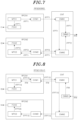
- FIG. 7 shows an example of a logical configuration of an RF controller and a control unit of a master RF generator device.
- FIG. 8 shows an example of a logical configuration of an RF controller and a control unit of a slave RF generator device.
- FIG. 9 shows an operation sequence of the master RF generator device and the slave RF generator devices.
- FIG. 10 A is a top view showing a first example of a configuration of a reactor having multiple antennas according to a second modification example.
- FIG. 10 B is a top view showing a second example of a configuration of a reactor having multiple antennas according to the second modification example.
- FIGS. 1 A and 1 B show a schematic configuration of a substrate processing apparatus having a radio frequency (RF) generator device according to an embodiment.
- FIG. 1 A shows a schematic configuration of the substrate processing apparatus
- FIG. 1 B shows a configuration of the RF generator device.
- RF radio frequency
- a substrate processing apparatus 1 includes a chamber 10 as a plasma reactor, two antennas ANT 1 and ANT 2 disposed in the chamber 10 , an RF generator device RFGD, and matching circuits MT 1 and MT 2 .
- the chamber 10 is a cylindrical reactor made of, for example, quartz.
- One or a plurality of substrates such as a semiconductor substrate are disposed in the chamber 10 and subjected to film formation using plasma or etching using plasma.
- the chamber 10 is illustrated as a cylindrical reactor in FIG. 1 A , the chamber 10 is not limited thereto.
- the chamber 10 may be a cube-shaped reactor.
- the substrate is not limited to a semiconductor substrate, and may be a glass substrate used for manufacturing a display panel.
- the antennas ANT 1 and ANT 2 are provided to generate plasma in the chamber 10 .
- the antenna ANT 1 is connected to an output of an RF generator RFG 1 of the RF generator device RFGD through the matching circuit MT 1 .
- the antenna ANT 2 is connected to an output of an RF generator RFG 2 of the RF generator device RFGD through the matching circuit MT 2 .
- the number of antennas may be three or more.
- the RF generator device RFGD includes the RF generator RFG 1 for generating RF power having a frequency f 1 and the RF generator RFG 2 for generating RF power having a frequency f 2 .
- the RF generator device RFGD includes a first port PT 1 to which the output of the RF generator RFG 1 is supplied and a second port PT 2 to which the output of the RF generator RFG 2 is supplied.
- the matching circuits MT 1 and MT 2 include elements such as a variable capacitor and the like, and perform impedance matching with plasma sources such as the antennas ANT 1 and ANT 2 .
- the RF generator device RFGD further includes an RF controller RFCN 1 for controlling the RF generator RFG 1 , an RF controller RFCN 2 for controlling the RF generator RFG 2 , and a control unit CNT for controlling the RF controllers RFCN 1 and RFCN 2 .
- the control unit CNT is a control module for controlling the entire RF generator device RFGD.
- the RF controller RFCN 1 and RFCN 2 are modules for controlling the RF outputs of the ports (the first port PT 1 and the second port PT 2 ) and the impedance matching.
- Each of the RF controllers RFCN 1 and RFCN 2 is connected to the control unit CNT by a low voltage differential signaling (LVDS) bus BUS and a control area network (CAN) bus CANBUS 1 , so that a bidirectional information transmission path is established. Further, the control unit CNT has a CAN interface CANIF and performs CAN communication with an external device while being connected to a CAN bus CANBUS 2 .
- LVDS low voltage differential signaling
- CAN control area network
- the RF controller RFCN 1 includes a fast Fourier transformer FFT 1 and a digital filter DF 1 .
- the RF controller RFCN 2 includes a fast Fourier transformer FFT 2 and a digital filter DF 2 .
- FIG. 1 A shows a traveling wave PF 1 outputted from the first port PT 1 being seen as a reflected wave of the second port PT 2 , and a traveling wave PF 2 outputted from the second port PT 2 being seen as a reflected wave of the first port PT 1 .
- An RF reflected wave PR 1 of a radio wave outputted from the first port PT 1 and an RF reflected wave PR 2 of a radio wave outputted from the second port PT 2 can be reduced by performing impedance matching using the matching circuits MT 1 and MT 2 .
- an interference wave PF 2 inputted to the first port PT 1 and the interference wave PF 1 inputted to the second port PT 2 cannot be reduced only by allowing the first port PT 1 and the second port PT 2 to individually perform their impedance matchings.
- the present disclosure suggests a frequency control method of an RF generator used for frequency matching to eliminate an effect of an interference wave at the time of matching operation.
- the RF generator device RFGD controls the frequencies of the RF outputs such that the respective frequencies of the RF outputs operate within a range where interference can be eliminated.
- Each of the fast Fourier transformers FFT 1 and FFT 2 of the RF controllers RFCN 1 and RFCN 2 performs fast Fourier transform (FFT) on a signal introduced as a reflected wave to decompose the signal into frequency components.
- the digital filter DF 1 or DF 2 of the RF controller RFCN 1 or RFCN 2 remove waves having the frequency components that are not outputted from the corresponding RF generator.
- the control unit CNT partially restricts the operation of frequency matching such that a difference between the frequencies (the frequency f 1 of the RF power of the RF generator RFG 1 and the frequency f 2 of the RF power of the RF generator RFG 2 ) is within a range where interference can be removed by attenuation in the digital filter DF 1 or DF 2 .
- FIG. 2 shows an example of a logical configuration of the RF controller and the control unit of FIG. 1 B .
- the RF controller RFCN 1 includes a matching operation unit MTC 1 , a frequency operating unit FCH 1 , and a communication unit COM 1 .
- the RF controller RFCN 2 includes a matching operation unit MTC 2 , a frequency operating unit FCH 2 , and a communication unit COM 2 .
- the control unit CNT includes a communication unit CMM 1 and a communication unit CMM 2 .
- a frequency setting method of the RF controller RFCN 1 and the RF controller RFCN 2 will be described with reference to FIG. 2 .
- the RF controller RFCN 1 is used as a master, and the RF controller RFCN 2 is used as a slave.
- the master and the slave can be determined by using DIP switches disposed in the RF controllers RFCN 1 and RFCN 2 .
- the master RF controller RFCN 1 does not particularly perform an operation for avoiding interference
- the slave RF controller RFCN 2 performs an operation for avoiding interference.
- the matching operation unit MTC 1 determines a frequency f 1 used for impedance matching of the first port PT 1 from a predetermined matching algorithm.
- the matching operation unit MTC 1 transmits frequency information IFPT 1 to the frequency operating unit FCH 1 .
- the frequency operating unit FCH 1 outputs RF power having the desired frequency f 1 from the RF generator RFG 1 of the first port PT 1 .
- the matching operation unit MTC 1 transmits the frequency information IFPT 1 to the communication unit COM 1 .
- the communication unit COM 1 outputs the frequency information IFPT 1 to the communication unit CMM 1 of the control unit CNT through the bus BUS.
- the communication unit CMM 1 outputs the frequency information IFPT 1 of the first port PT 1 to the communication unit CMM 2 .
- the communication unit CMM 2 outputs the frequency information IFPT 1 of the first port PT 1 to the communication unit COM 2 of the RF controller RFCN 2 through the bus BUS.
- the communication unit COM 2 outputs the frequency information IFPT 1 of the first port PT 1 to the matching operation unit MTC 2 .
- the matching operation unit MTC 2 of the RF controller RFCN 2 compares the frequency information IFPT 1 of the first port PT 1 inputted from the communication unit COM 2 with a frequency calculated from a predetermined matching algorithm to determine a frequency f 2 used for impedance matching of the second port PTS.
- the matching operation unit MTC 2 outputs frequency information IFPT 2 of the second port PT 2 to the frequency operating unit FCH 2 . Accordingly, the frequency operating unit FCH 2 outputs RF power having the desired frequency f 2 from the RF generator RFG 2 of the second port PT 2 .
- FIG. 3 is a flowchart showing a frequency comparison method in the RF controller RFCN 2 of the second port PT 2 .
- “f 1 ” indicates the output frequency of the first port PT 1
- “f 2 ” indicates the output frequency of the second port PT 2 .
- the RF controller RFCN 2 determines a frequency “a MHz” required for impedance matching calculated by the matching operation unit MTC 2 . However, when a difference frequency with the frequency f 1 on the first port PT 1 side is within 10 kHz, a value at which the difference frequency with the frequency f 1 becomes 10 kHz is finally adopted.
- 10 kHz is the minimum value of a frequency band in which interference between the first port PT 1 and the second port PT 2 can be suppressed by the digital filter DF 1 and DF 2 .
- the difference frequency of 10 kHz is obtained in the case of using the undersampling technique for the digital filters DF 1 and DF 2 . If the oversampling technique is used for the digital filters DF 1 and DF 2 , the difference frequency can be adjusted to be, for example, 1 kHz, which is smaller than 10 kHz.
- Step S 1 The matching operation is started.
- Step S 2 It is determined whether or not the matching operation is completed. If the matching operation is not completed (NO in step S 2 ), the process proceeds to step S 3 . When the matching operation is completed (YES in step S 2 ), the process proceeds to step S 4 , and the matching operation is terminated.
- 28.12 MHz is a maximum frequency that can be outputted from the RF generator device RFGD. If f 1 and f 2 are not equal to 28.12 MHz, the process proceeds to step S 6 . If f 1 and f 2 are equal to 28.12 MHz, the process proceeds to step S 7 .
- f 1 is 28.12 MHz.
- 26.12 MHz is a minimum frequency that can be outputted from the RF generator device RFGD. If f 1 and f 2 are not equal to 26.12 MHz, the process proceeds to step S 8 . If f 1 and f 2 are equal to 26.12 MHz, the process proceeds to step S 9 .
- f 1 is 26.12 MHz.
- step S 14 the process proceeds to step S 2 to determine again whether or not the matching operation is completed.
- FIG. 4 shows an operation sequence of the RF controller and the control unit.
- “f 11 ” and “f 12 ” indicate the frequencies of the RF generator RFG 1 of the first port PT 1
- “f 21 ” and “f 22 ” indicate the frequencies of the RF generator RFG 2 of the second port PT 2
- “f 11 ” and “f 21 ” indicate first setting values
- f 12 and f 22 indicate second setting values.
- the RF controller RFCN 1 performs a first matching operation using a predetermined matching algorithm to set the frequency f 11 of the RF generator RFG 1 of the first port PT 1 .
- the information of the set frequency f 11 is transmitted, as the frequency information IFPT 1 of the first port PT 1 , to the RF controller RFCN 2 through the control unit CNT.
- the RF controller RFCN 2 performs a first matching operation using a predetermined matching algorithm and the frequency comparison shown in FIG. 3 while referring to the received information IFPT 1 of the frequency f 11 to set the frequency f 21 of the RF generator RFG 2 of the second port PT 2 .
- the RF controller RFCN 1 performs a second matching operation using a predetermined matching algorithm when, for example, 4 ms has elapsed from the first matching operation to set the frequency f 12 of the RF generator RFG 1 of the first port PT 1 .
- the information of the set frequency f 12 is transmitted, as the frequency information IFPT 1 of the first port PT 1 , to the RF controller RFCN 2 through the control unit CNT.
- the RF controller RFCN 2 performs a second matching operation using a predetermined matching algorithm and the frequency comparison shown in FIG. 3 while referring to the received information IFPT 1 of the frequency f 12 when, for example, 4 ms has elapsed from the first matching operation to set the frequency f 22 of the RF generator RFG 2 of the second port PT 2 .
- the output powers of the RF generators RFG 1 and RFG 2 can be controlled and the frequency interference can be avoided.
- the impedance matching can be performed while avoiding the frequency interference between the multiple output ports (the first port and the second port). Therefore, in the substrate processing apparatus in which the multiple antennas are disposed in the reactor 10 (chamber), a correct matching operation can be performed, which makes it possible to generate stable and high-quality plasma in the reactor 10 (chamber). Accordingly, the stable plasma processing can be performed on the substrate.
- FIG. 5 shows a schematic configuration of a substrate processing apparatus having multiple RF generator devices according to a first modification example.
- multiple antennas ANT 1 to ANTn and multiple RF generator devices RFGD 0 to RFGDn are disposed in the chamber 10 that is a reactor.
- Each of the RF generator devices RFGD 0 to RFGDn has the same configuration as that of the RF generator device RFGD shown in FIG. 1 B .
- the antennas ANT 1 and ANT 2 are connected to the RF generator device RFGD 0
- the antennas ANT 3 and ANT 4 are connected to the RF generator device RFGD 1 .
- the antennas ANT 5 and ANT 6 are connected to the RF generator device RFGD 2
- the antennas ANT 2 n+ 1 and ANT 2 n+ 2 are connected to the RF generator device RFGDn.
- the RF generator devices RFGD 0 to RFGDn are connected through a CAN bus CANBUS 2 .
- the RF generator device RFGD 0 is set as a master MS
- the other RF generator devices RFGD 1 to RFGDn are set as slaves SLV.
- the master MS and the slaves SLV are determined and identified by using the DIP switches respectively disposed at the control units CNT of the RF generator devices RFGD 0 to RFGDn.
- the RF generator device RFGD 0 serving as the master MS is configured to transmit the information of the output frequencies f 1 and f 2 of the RF powers generated by the RF generators RFG 1 and RFG 2 in the RF generator device RFGD 0 to the RF generator devices RFGD 1 to RFGDn serving as the slaves SLV through broadcast communication with the CAN bus CANBUS 2 .
- FIG. 6 shows an example of allocating output frequencies of the multiple RF generator devices of FIG. 5 .
- Each of the RF generator devices RFGD 0 to RFGDn is configured to generate RF power having an output frequency ranging between 26.12 MHz and 28.12 MHz, for example.
- the RF generator device RFGD 0 generates the RF powers having the output frequencies f 1 and f 2 .
- the difference frequency between the frequency f 1 and the frequency f 2 is within a range in which interference can be removed by attenuation in the digital filter DF 1 or DF 2 .
- the difference frequency is 10 kHz.
- the RF generator device RFGD 1 generates RF powers having output frequencies f 3 and f 4 .
- a difference frequency between the frequency f 3 and the frequency f 4 may be, e.g., 10 kHz. Further, a difference frequency between the frequency f 2 and the frequency f 3 may be, for example, 10 kHz. Further, the RF generator device RFGD 2 generates RF powers having output frequencies f 5 and f 6 . In the same manner as above, a difference frequency between the frequency f 5 and the frequency f 6 may be, for example, 10 kHz. Further, a difference frequency between the frequency f 4 and the frequency f 5 may be, for example, 10 kHz. Further, the RF generator device RFGDn generates RF powers having output frequencies f 2 n +1 and f 2 n +2. In the same manner as above, a difference frequency between the frequency f 2 n +1 and the frequency f 2 n +2 may be, for example, 10 kHz.
- the frequency range between 26.12 MHz and 28.12 MHz can be effectively utilized, and interference can be avoided in each of the RF generator devices RFGD 0 to RFGDn.
- the frequency setting shown in FIG. 6 can be automatically performed using the value of the DIP switch.
- the master RF generator device RFGD 0 and the slave RF generator devices RFGDn determine ID numbers thereof using the values (e.g., 0 to 15) of the DIP switches thereof. Specifically, the ID number of the master MS is set to 0, and the ID numbers of the slaves SLV are set to 1 to 15.
- the slave SLV is set to a frequency separated by 10 kHz ⁇ n from the value of the frequency received from the master MS.
- n indicates an ID number of each slave, and satisfies a condition “n ⁇ 1.”
- CANID set for the RF generator devices RFGD 0 to RFGDn.
- FIG. 7 shows an example of a logical configuration of the RF controller and the control unit of the master RF generator device.
- FIG. 8 shows an example of a logical configuration of the RF controller and the control unit of the slave RF generator device.
- the configuration shown in FIG. 7 is different from that shown in FIG. 2 in that the RF controller RFCN 2 of the master RF generator device RFGD 0 outputs the frequency information IFPT 2 of the second port PT 2 from the matching operation unit MTC 2 to the communication unit CMM 2 of the control unit CNT through the communication unit COM 2 and also in that an external communication unit CMM 3 , added to the control unit CNT of the RF generator device RFGD 0 , receives the frequency information IFPT 1 from the communication unit CMM 1 and the frequency information IFPT 2 from the communication unit CMM 2 and transmits frequency information IFM of the master RF generator device RFGD 0 .
- the frequency information IFM includes the frequency information IFPT 1 and the frequency information IFPT 2 .
- the external communication unit CMM 3 outputs the frequency information IFM to the slave RF generator device RFGD 1 through the CAN bus CANBUS 2 .
- the frequency setting method of the RF controller RFCN 1 and the RF controller RFCN 2 of the RF generator device RFGD 0 will be described with reference to FIG. 7 .
- the matching operation unit MTC 1 determines the frequency f 1 used for impedance matching of the first port PT 1 from a predetermined matching algorithm.
- the matching operation unit MTC 1 transmits the frequency information IFPT 1 to the frequency operating unit FCH 1 , and the frequency operating unit FCH 1 outputs RF power having the desired frequency f 1 from the RF generator RFG 1 of the first port PT 1 .
- the matching operation unit MTC 1 transmits the frequency information IFPT 1 to the communication unit COM 1 , and the communication unit COM 1 outputs the frequency information IFPT 1 to the communication unit CMM 1 of the control unit CNT through the bus BUS.
- the communication unit CMM 1 outputs the frequency information IFPT 1 of the first port PT 1 to the communication unit CMM 2 and the external communication unit CMM 3 .
- the communication unit CMM 2 outputs the frequency information IFPT 1 of the first port PT 1 to the communication unit COM 2 of the RF controller RFCN 2 through the bus BUS.
- the communication unit COM 2 outputs the frequency information IFPT 1 of the first port PT 1 to the matching operation unit MTC 2 .
- the matching operation unit MTC 2 of the RF controller RFCN 2 compares the frequency information IFPT 1 of the first port PT 1 inputted from the communication unit COM 2 with a frequency calculated from a predetermined matching algorithm to determine a frequency f 2 used for the impedance matching of the second port PT 2 .
- the matching operation unit MTC 2 outputs the frequency information IFPT 2 of the second port PT 2 to the frequency operating unit FCH 2 . Accordingly, the frequency operating unit FCH 2 outputs RF power of the desired frequency f 2 from the RF generator RFG 2 of the second port PT 2 .
- the matching operation unit MTC 2 outputs the frequency information IFPT 2 of the second port PT 2 to the communication unit COM 2 .
- the communication unit COM 2 outputs the frequency information IFPT 2 of the second port PT 2 to the communication unit CMM 2 .
- the communication unit CMM 2 outputs the frequency information IFPT 2 of the second port PT 2 to the external communication unit CMM 3 .
- the external communication unit CMM 3 outputs the frequency information IFPT 1 of the first port PT 1 and the frequency information IFPT 2 of the second port PT 2 , as the frequency information IFM of the master, to the slave RF generator device RFGD 1 through the CAN bus CANBUS 2 .
- the RF controller RFCN 1 of the slave RF generator device RFGD 1 includes a matching operation unit MTC 1 , a frequency operating unit FCH 1 , and a communication unit COM 1 .
- the RF controller RFCN 2 of the RF generator device RFGD 1 includes a matching operation unit MTC 2 , a frequency operating unit FCH 2 , and a communication unit COM 2 .
- the control unit CNT of the RF generator device RFGD 1 includes a communication unit CMM 1 , a communication unit CMM 2 , and an external communication unit CMM 3 .
- the frequency setting method of the RF controller RFCN 1 and the RF controller RFCN 2 of the RF generator device RFGD 1 will be described with reference to FIG. 8 .
- the external communication unit CMM 3 receives the frequency information IFM of the master through the CAN bus CANBUS 2 , and outputs the received frequency information IFM to the communication unit CMM 1 .
- the communication unit CMM 1 outputs the frequency information IFM of the master to the communication unit COM 1 .
- the communication unit COM 1 outputs the frequency information IFM of the master to the matching operation unit MTC 1 .
- the matching operation unit MTC 1 compares the frequency information IMF (IFPT 1 and IFPT 2 ) of the master inputted from the communication unit COM 1 with a frequency calculated from a predetermined matching algorithm to determine a frequency f 3 used for impedance matching of the first port PT 1 on the slave side.
- the matching operation unit MTC 1 transmits the determined frequency f 3 as frequency information IFPT 1 S to the frequency operating unit FCH 1 , and outputs the RF power having the frequency f 3 from the RF generator RFG 1 of the first port PT 1 on the slave side.
- the matching operation unit MTC 1 outputs the determined frequency information IFPT 1 S of the first port PT 1 to the communication unit COM 1 .
- the communication unit COM 1 outputs the inputted frequency information IFPT 1 S of the first port PT 1 to the communication unit CMM 1 .
- the communication unit CMM 1 outputs the frequency information IFPT 1 S of the first port PT 1 to the communication unit CMM 2 .
- the communication unit CMM 2 outputs the frequency information IFPT 1 S of the first port PT 1 to the communication unit COM 2 .
- the communication unit COM 2 outputs the frequency information IFPT 1 S of the first port PT 1 to the matching operation unit MTC 2 .
- the matching operation unit MTC 2 compares the frequency information IFPT 1 S of the first port PT 1 inputted from the communication unit COM 2 with a frequency calculated from a predetermined matching algorithm to determine a frequency f 4 used for impedance matching of the second port PT 2 .
- the matching operation unit MTC 2 transmits the determined frequency f 4 as frequency information IFPT 2 S to the frequency operating unit FCH 2 , and outputs the RF power having the frequency f 4 from the RF generator RFG 2 of the second port PT 2 on the slave side.
- FIG. 9 shows an operation sequence of the master RF generator device and the slave RF generator devices.
- “f 11 ” and “f 12 ” indicate the frequencies of the RF generator RFG 1 of the first port PT 1 of the master RF generator device RFGD 0 (MS)
- “f 21 ” and “f 22 ” indicate the frequencies of the RF generator RFG 2 of the second port PT 2 of the master RF generator device RFGD 0 (MS).
- “f 11 ” and “f 21 ” indicate first setting values
- “f 12 ” and “f 22 ” indicate second setting values.
- f 11 S and “f 12 S” indicate the frequencies of the RF generator RFG 1 of the first port PT 1 of the slave RF generator device RFGDn (SLV)
- f 21 S and “f 22 S” indicate the frequencies of the RF generator RFG 2 of the second port PT 2 of the slave RF generator device RFGDn (SLV).
- f 11 S” and “f 21 S” indicate first setting values
- “f 12 S” and “f 22 S” indicate second setting values.
- the RF generator device RFGDn (SLV) is the RF generator device RFGD 1 (SLV)
- the following “f 11 S” and “f 12 S” correspond to the frequency f 3 of FIG. 8
- the following “f 21 S” and “f 22 S” correspond to the frequency f 4 of FIG. 8 .
- the RF controller RFCN 1 performs a first matching operation using a predetermined matching algorithm to set the frequency f 11 of the RF generator RFG 1 of the first port PT 1 .
- the information of the set frequency f 11 is transmitted, as the frequency information IFPT 1 of the first port PT 1 , to the RF controller RFCN 2 through the control unit CNT.
- the RF controller RFCN 2 performs a first matching operation using a predetermined matching algorithm and the frequency comparison shown in FIG. 3 while referring to the received information IFPT 1 of the frequency f 11 to set the frequency f 21 of the RF generator RFG 2 of the second port PT 2 .
- the RF controller RFCN 2 transmits the information of the frequency f 21 , as the frequency information IFPT 2 of the second port PT 2 , to the control unit CNT.
- the control unit CNT transmits a first frequency information IFM 1 including the frequency information IFPT 1 and the frequency information IFPT 2 to the control unit CNT of the RF generator device RFGDn (SLV).
- the RF controller RFCN 1 performs a second matching operation using a predetermined matching algorithm when, for example, 4 ms has elapsed from the first matching operation to set the frequency f 12 of the RF generator RFG 1 of the first port PT 1 .
- the information of the set frequency f 12 is transmitted, as the frequency information IFPT 1 of the first port PT 1 , to the RF controller RFCN 2 through the control unit CNT.
- the RF controller RFCN 2 performs a second matching operation using a predetermined matching algorithm and the frequency comparison shown in FIG. 3 while referring to the received information IFPT 1 of the frequency f 12 when, for example, 4 ms has elapsed from the first matching operation and the frequency comparison to set the frequency f 22 of the RF generator RFG 2 of the second port PT 2 .
- the RF controller RFCN 2 transmits the information of the frequency f 22 , as the frequency information IFPT 2 of the second port PT 2 , to the control unit CNT.
- the control unit CNT transmits the second frequency information IFM 2 including the frequency information IFPT 1 and the frequency information IFPT 2 to the control unit CNT of the RF generator device RFGDn (SLV).
- the control unit CNT that has received the first frequency information IFM 1 transmits the frequency information IFM 2 to the RF controller RFCN 1 .
- the RF controller RFCN 1 performs a first matching operation using a predetermined matching algorithm and the frequency comparison shown in FIG. 3 while referring to the received frequency information IFM 2 to set the frequency f 11 S of the RF generator RFG 1 of the first port PT 1 .
- the information of the set frequency f 11 S is transmitted, as the frequency information IFPT 1 S of the first port PT 1 , to the RF controller RFCN 2 through the control unit CNT.
- the RF controller RFCN 2 performs a first matching operation using a predetermined matching algorithm and the frequency comparison shown in FIG. 3 while referring to the received information IFPT 1 S of the frequency f 11 S to set the frequency f 21 S of the RF generator RFG 2 of the second port PT 2 .
- the control unit CNT that has received the second frequency information IFM 2 transmits the frequency information IFM 1 to the RF controller RFCN 1 .
- the RF controller RFCN 1 performs a second matching operation using a predetermined matching algorithm and the frequency comparison while referring to the received frequency information IFM 1 when, for example, 4 ms has elapsed from the first matching operation and the frequency comparison to set the frequency f 12 S of the RF generator RFG 1 of the first port PT 1 .
- the information of the set frequency f 12 S is transmitted, as the frequency information IFPT 1 S of the first port PT 1 , to the RF controller RFCN 2 through the control unit CNT.
- the RF controller RFCN 2 performs a second matching operation using a predetermined matching algorithm and the frequency comparison shown in FIG. 3 while referring to the received information IFPT 1 S of the frequency f 12 S when, for example, 4 ms has elapsed from the first matching operation and the frequency comparison to set the frequency f 22 S of the RF generator RFG 2 of the second port PT 2 .
- the output frequencies of the RF powers generated from the respective ports of the RF generator device RFGD 0 (MS) and the RF generator device RFGDn (SLV) can be set such that the impedance matching can be performed while avoiding frequency interference.
- the correct matching operation can be performed so that stable and high-quality plasma can be generated in the reactor of the substrate processing apparatus. Accordingly, the processing using stable plasma can be performed on the substrate.
- the same control software can be used for the master RF generator device and the slave RF generator devices. Therefore, it is not necessary to separately develop the software for the master RF generator device and the software for the slave RF generator devices, which is cost-effective. Hence, the software development cost can be reduced.
- FIGS. 10 A and 10 B are top views of a reactor provided with multiple antennas according to the second modification example.
- FIGS. 10 A and 10 B show an example of a configuration in which sixteen antennas are arranged in the chamber (reactor) 10 of the substrate processing apparatus 1 .
- the sixteen antennas are disposed on a ceiling wall of the chamber (reactor) 10 to be positioned above the substrate disposed in the chamber (reactor) 10 .
- the substrate is, for example, a glass substrate used for manufacturing a display panel.
- FIG. 10 A shows a first example of a configuration in which sixteen antennas A to P are arranged in the chamber 10 (on the ceiling wall) in a matrix shape in rows and columns at equal intervals.
- the RF powers are supplied from the RF generators RFG 1 to RFG 16 to the antennas A to P through the matching units, respectively.
- the RF generator RFG 1 is connected to the antenna A to supply the RF power having the frequency f 1 through the matching unit.
- the RF generator RFG 2 is connected to the antenna B to supply the RF power having the frequency f 2 through the matching unit.
- the output frequencies f 1 to f 16 of the RF generators RFG 1 to RFG 16 are set such that the frequency interference can be avoided as described with reference to FIGS. 5 and 6 .
- the number of the RF generators having different output frequencies is equal to the number of the antennas.
- the contents managed by the system may increase.
- the exchange of frequency information is required.
- the size and the cost may also increase.
- FIG. 10 B shows a second example of a configuration in which sixteen antennas are arranged in the chamber 10 (at a ceiling wall) in a matrix shape in rows and columns at equal intervals.
- the RF powers of different frequencies are supplied to the antennas.
- the sixteen antennas are classified into, e.g., four groups A, B, C, and D.
- the antennas A of the first group are connected to the RF generator RFG 1 that outputs the RF power having the frequency f 1 through the matching unit.
- the antennas B of the second group are connected to the RF generator RFG 2 that outputs the RF power having the frequency f 2 through the matching unit.
- the antennas C of the third group are connected to the RF generator RFG 3 that outputs the RF power having the frequency f 3 through the matching unit.
- the antennas D of the fourth group are connected to the RF generator RFG 4 that outputs the RF power having the frequency f 4 through the matching unit.
- the output frequencies f 1 to f 4 of the RF generators RFG 1 to RFG 4 are set such that the frequency interference can be avoided as described with reference to FIGS. 5 and 6 .
- the antennas of other groups are arranged around the antenna A of the first group.
- the number of the groups (four groups in this example) is smaller than the number of antennas (sixteen antennas in this example). Further, the number of the groups (four groups in this example) is equal to the number of the RF generators (four RF generators RFG 1 to RFG 4 in this example).
- the interference that occurs in the chamber 10 may possibly be avoided as a physical distance increases. Therefore, when the antennas are spaced apart from each other by a certain distance (in other words, when there can be a high occurrence of interference between the adjacent antennas and the interference can be avoided by increasing the distance therebetween), the same frequency may be used for the antennas that are not adjacent to each other. In other words, as shown in FIG. 10 B , the same frequency is used for the physically separated antennas. Accordingly, compared to the case where sixteen frequencies f 1 to f 16 and sixteen RF generators RFG 1 to RFG 16 are required as shown in FIG. 10 A , the number of the frequencies and the number of the RF generators can be reduced to the four frequencies f 1 to f 4 and the four RF generators RFG 1 to RFG 4 as shown in FIG. 10 B .
- the frequency management can become simpler by reducing the types of frequencies and the required number of the RF generators.
- the output of each of the RF generators RFG 1 to RFG 4 can be increased by four times and divided into four.
- an RF generator device capable of eliminating an effect of an interference wave at the time of impedance matching.
Landscapes
- Physics & Mathematics (AREA)
- Engineering & Computer Science (AREA)
- Plasma & Fusion (AREA)
- Chemical & Material Sciences (AREA)
- Analytical Chemistry (AREA)
- Discrete Mathematics (AREA)
- General Physics & Mathematics (AREA)
- Mathematical Physics (AREA)
- Computer Networks & Wireless Communication (AREA)
- Signal Processing (AREA)
- Electromagnetism (AREA)
- Spectroscopy & Molecular Physics (AREA)
- Plasma Technology (AREA)
Abstract
Description
- Patent Document 1: Japanese Patent Application Publication No. 2014-239029
- Patent Document 2: International Patent Application Publication No. WO2004/064460
- Patent Document 3: Japanese Patent Application Publication No. 2004-228354
- Patent Document 4: Japanese Patent Application Publication No. 2005-532668
-
- 1: Substrate processing apparatus
- 10: Chamber (reactor)
- MT1, MT2: Matching unit
- ANT1, ANT2: Antenna
- RFGD: RF generator device
- RFG1, RFG2: RF generator
- RFCN1, RFCN2: RF controller
- CNT: Control unit
- FFT1, FFT2: Fast Fourier transformer
- DF1, DF2: Digital filter
- MTC1, MTC2: Matching operation unit
- FCH1, FCH2: Frequency operating unit
- COM1, COM2, CMM1, CMM2: Communication unit
- CMM3: External communication unit
Claims (10)
Applications Claiming Priority (1)
| Application Number | Priority Date | Filing Date | Title |
|---|---|---|---|
| PCT/JP2018/033906 WO2020054005A1 (en) | 2018-09-13 | 2018-09-13 | High-frequency power supply device and substrate processing device |
Publications (2)
| Publication Number | Publication Date |
|---|---|
| US20220115210A1 US20220115210A1 (en) | 2022-04-14 |
| US11901159B2 true US11901159B2 (en) | 2024-02-13 |
Family
ID=69776986
Family Applications (1)
| Application Number | Title | Priority Date | Filing Date |
|---|---|---|---|
| US17/268,100 Active 2039-12-31 US11901159B2 (en) | 2018-09-13 | 2018-09-13 | RF generator device and substrate processing apparatus |
Country Status (4)
| Country | Link |
|---|---|
| US (1) | US11901159B2 (en) |
| JP (1) | JP7058748B2 (en) |
| KR (1) | KR102541816B1 (en) |
| WO (1) | WO2020054005A1 (en) |
Families Citing this family (1)
| Publication number | Priority date | Publication date | Assignee | Title |
|---|---|---|---|---|
| CN117998716A (en) * | 2022-11-01 | 2024-05-07 | 中微半导体设备(上海)股份有限公司 | Capacitively coupled plasma processor |
Citations (15)
| Publication number | Priority date | Publication date | Assignee | Title |
|---|---|---|---|---|
| JPS62273731A (en) | 1986-05-21 | 1987-11-27 | Tokyo Electron Ltd | Plasma processor |
| US5401350A (en) * | 1993-03-08 | 1995-03-28 | Lsi Logic Corporation | Coil configurations for improved uniformity in inductively coupled plasma systems |
| US5571366A (en) * | 1993-10-20 | 1996-11-05 | Tokyo Electron Limited | Plasma processing apparatus |
| JPH09120898A (en) | 1995-07-26 | 1997-05-06 | Applied Materials Inc | Plasma source with electronically variable density profile |
| US5907221A (en) * | 1995-08-16 | 1999-05-25 | Applied Materials, Inc. | Inductively coupled plasma reactor with an inductive coil antenna having independent loops |
| US20040007984A1 (en) | 2002-07-10 | 2004-01-15 | Coumou David J. | Multirate processing for metrology of plasma rf source |
| JP2004152606A (en) | 2002-10-30 | 2004-05-27 | Matsushita Electric Ind Co Ltd | High frequency power supply |
| WO2004064460A1 (en) | 2003-01-16 | 2004-07-29 | Japan Science And Technology Agency | High frequency power supply device and plasma generator |
| JP2004228354A (en) | 2003-01-23 | 2004-08-12 | Japan Science & Technology Agency | Plasma generator |
| US20060225653A1 (en) * | 2003-07-25 | 2006-10-12 | Xu Shu Y | Apparatus and method for generating uniform plasmas |
| US20080206483A1 (en) * | 2007-02-26 | 2008-08-28 | Alexander Paterson | Plasma process for inductively coupling power through a gas distribution plate while adjusting plasma distribution |
| US20100304046A1 (en) | 2002-12-16 | 2010-12-02 | Shoji Miyake | Plasma generator, plasma control method and method of producing substrate |
| US20140320013A1 (en) | 2013-04-26 | 2014-10-30 | Mks Instruments, Inc. | Multiple Radio Frequency Power Supply Control of Frequency and Phase |
| US20150311040A1 (en) | 2014-04-25 | 2015-10-29 | Hitachi High-Technologies Corporation | Plasma processing apparatus |
| WO2017014210A1 (en) | 2015-07-21 | 2017-01-26 | 東京エレクトロン株式会社 | Plasma processing device and plasma processing method |
Family Cites Families (1)
| Publication number | Priority date | Publication date | Assignee | Title |
|---|---|---|---|---|
| KR101151414B1 (en) * | 2010-02-23 | 2012-06-04 | 주식회사 플라즈마트 | Impedance matching apparatus |
-
2018
- 2018-09-13 US US17/268,100 patent/US11901159B2/en active Active
- 2018-09-13 WO PCT/JP2018/033906 patent/WO2020054005A1/en not_active Ceased
- 2018-09-13 JP JP2020546613A patent/JP7058748B2/en active Active
- 2018-09-13 KR KR1020217003526A patent/KR102541816B1/en active Active
Patent Citations (20)
| Publication number | Priority date | Publication date | Assignee | Title |
|---|---|---|---|---|
| JPS62273731A (en) | 1986-05-21 | 1987-11-27 | Tokyo Electron Ltd | Plasma processor |
| US5401350A (en) * | 1993-03-08 | 1995-03-28 | Lsi Logic Corporation | Coil configurations for improved uniformity in inductively coupled plasma systems |
| US5571366A (en) * | 1993-10-20 | 1996-11-05 | Tokyo Electron Limited | Plasma processing apparatus |
| JPH09120898A (en) | 1995-07-26 | 1997-05-06 | Applied Materials Inc | Plasma source with electronically variable density profile |
| US5907221A (en) * | 1995-08-16 | 1999-05-25 | Applied Materials, Inc. | Inductively coupled plasma reactor with an inductive coil antenna having independent loops |
| JP2005532668A (en) | 2002-07-10 | 2005-10-27 | イーエヌアイ テクノロジー, インコーポレイテッド | Multi-rate processing for plasma RF source measurement |
| US20040007984A1 (en) | 2002-07-10 | 2004-01-15 | Coumou David J. | Multirate processing for metrology of plasma rf source |
| JP2004152606A (en) | 2002-10-30 | 2004-05-27 | Matsushita Electric Ind Co Ltd | High frequency power supply |
| US20100304046A1 (en) | 2002-12-16 | 2010-12-02 | Shoji Miyake | Plasma generator, plasma control method and method of producing substrate |
| US20060057854A1 (en) | 2003-01-16 | 2006-03-16 | Yuichi Setsuhara | High frequency power supply device and plasma generator |
| WO2004064460A1 (en) | 2003-01-16 | 2004-07-29 | Japan Science And Technology Agency | High frequency power supply device and plasma generator |
| JP2004228354A (en) | 2003-01-23 | 2004-08-12 | Japan Science & Technology Agency | Plasma generator |
| US20060225653A1 (en) * | 2003-07-25 | 2006-10-12 | Xu Shu Y | Apparatus and method for generating uniform plasmas |
| US20080206483A1 (en) * | 2007-02-26 | 2008-08-28 | Alexander Paterson | Plasma process for inductively coupling power through a gas distribution plate while adjusting plasma distribution |
| US20140320013A1 (en) | 2013-04-26 | 2014-10-30 | Mks Instruments, Inc. | Multiple Radio Frequency Power Supply Control of Frequency and Phase |
| JP2014239029A (en) | 2013-04-26 | 2014-12-18 | エムケーエス インストゥルメンツ,インコーポレイテッド | Control of frequencies and phases of a plurality of radio frequency power supply apparatuses |
| US20150311040A1 (en) | 2014-04-25 | 2015-10-29 | Hitachi High-Technologies Corporation | Plasma processing apparatus |
| JP2015211093A (en) | 2014-04-25 | 2015-11-24 | 株式会社日立ハイテクノロジーズ | Plasma processing device |
| WO2017014210A1 (en) | 2015-07-21 | 2017-01-26 | 東京エレクトロン株式会社 | Plasma processing device and plasma processing method |
| US20180211818A1 (en) | 2015-07-21 | 2018-07-26 | Tokyo Electron Limited | Plasma processing apparatus and plasma processing method |
Non-Patent Citations (1)
| Title |
|---|
| International Search Report cited in International Appln. No. PCT/JP2018/033906 dated Nov. 20, 2018. |
Also Published As
| Publication number | Publication date |
|---|---|
| JP7058748B2 (en) | 2022-04-22 |
| KR20210024172A (en) | 2021-03-04 |
| KR102541816B1 (en) | 2023-06-13 |
| US20220115210A1 (en) | 2022-04-14 |
| WO2020054005A1 (en) | 2020-03-19 |
| JPWO2020054005A1 (en) | 2021-05-20 |
Similar Documents
| Publication | Publication Date | Title |
|---|---|---|
| KR102799816B1 (en) | Multiple-output radiofrequency matching module and associated methods | |
| US10699884B2 (en) | Plasma processing apparatus and plasma processing method | |
| SG182969A1 (en) | Distributed power arrangements for localizing power delivery | |
| CN104901025B (en) | A kind of implementation method and device, Anneta module of Anneta module | |
| US11901159B2 (en) | RF generator device and substrate processing apparatus | |
| TW202333540A (en) | Plasma processing apparatus and processing method | |
| JP6180890B2 (en) | Plasma processing method | |
| CN109659217A (en) | Radio frequency system for more plasma processing chambers | |
| US8937517B2 (en) | Splitter | |
| KR102000621B1 (en) | RF power distribution apparatus and RF power distribution method | |
| KR101914902B1 (en) | Apparatus for generating plasma and apparatus for treating substrate having the same | |
| KR102901676B1 (en) | The stack type matcher | |
| KR102811324B1 (en) | A generator having power control sync | |
| US20240072842A1 (en) | Industrial wireless communication system | |
| KR20110134217A (en) | Plasma chamber with feeder for multiple split electrode sets | |
| US11810759B2 (en) | RF generator | |
| WO2023143732A1 (en) | Radar signal generator arrangement, radar arrangement and radar system | |
| KR20130071292A (en) | System and method for controlling disparate phase over a rf plasma system | |
| KR102855356B1 (en) | Power supply device, power supply method and plasma processing apparatus | |
| US20200348716A1 (en) | Method for configuring master/slave in double board, and board thereof | |
| US20260106113A1 (en) | Control of rf power delivery and splitting in a distributed rf system | |
| KR20160068544A (en) | The power distributor for plasma process apparatus and the plasma process apparatus having same | |
| KR102809946B1 (en) | The multi rf generator | |
| KR20240084124A (en) | The rf generator | |
| KR20240052325A (en) | A apparatus for supplying the radiofrequency power by multi-channel |
Legal Events
| Date | Code | Title | Description |
|---|---|---|---|
| AS | Assignment |
Owner name: HITACHI KOKUSAI ELECTRIC INC., JAPAN Free format text: ASSIGNMENT OF ASSIGNORS INTEREST;ASSIGNORS:TAKAHASHI, NAOTO;FUJIMOTO, NAOYA;EGASHIRA, SUNAO;AND OTHERS;REEL/FRAME:055240/0713 Effective date: 20210114 |
|
| FEPP | Fee payment procedure |
Free format text: ENTITY STATUS SET TO UNDISCOUNTED (ORIGINAL EVENT CODE: BIG.); ENTITY STATUS OF PATENT OWNER: LARGE ENTITY |
|
| STPP | Information on status: patent application and granting procedure in general |
Free format text: DOCKETED NEW CASE - READY FOR EXAMINATION |
|
| STPP | Information on status: patent application and granting procedure in general |
Free format text: NON FINAL ACTION MAILED |
|
| STPP | Information on status: patent application and granting procedure in general |
Free format text: RESPONSE TO NON-FINAL OFFICE ACTION ENTERED AND FORWARDED TO EXAMINER |
|
| STPP | Information on status: patent application and granting procedure in general |
Free format text: NOTICE OF ALLOWANCE MAILED -- APPLICATION RECEIVED IN OFFICE OF PUBLICATIONS |
|
| STPP | Information on status: patent application and granting procedure in general |
Free format text: PUBLICATIONS -- ISSUE FEE PAYMENT VERIFIED |
|
| STCF | Information on status: patent grant |
Free format text: PATENTED CASE |
|
| AS | Assignment |
Owner name: KOKUSAI DENKI ELECTRIC INC., JAPAN Free format text: CHANGE OF NAME;ASSIGNOR:HITACHI KOKUSAI ELECTRIC INC.;REEL/FRAME:071275/0236 Effective date: 20241227 Owner name: HITACHI KOKUSAI ELECTRIC INC., JAPAN Free format text: CHANGE OF ADDRESS;ASSIGNOR:HITACHI KOKUSAI ELECTRIC INC.;REEL/FRAME:071275/0058 Effective date: 20161001 |