US11899573B2 - Memory system - Google Patents
Memory system Download PDFInfo
- Publication number
- US11899573B2 US11899573B2 US17/684,576 US202217684576A US11899573B2 US 11899573 B2 US11899573 B2 US 11899573B2 US 202217684576 A US202217684576 A US 202217684576A US 11899573 B2 US11899573 B2 US 11899573B2
- Authority
- US
- United States
- Prior art keywords
- garbage collection
- logical blocks
- valid data
- collection target
- logical block
- Prior art date
- Legal status (The legal status is an assumption and is not a legal conclusion. Google has not performed a legal analysis and makes no representation as to the accuracy of the status listed.)
- Active, expires
Links
- 238000000034 method Methods 0.000 claims description 67
- 230000008569 process Effects 0.000 description 41
- 238000013523 data management Methods 0.000 description 29
- 238000007726 management method Methods 0.000 description 17
- 238000010586 diagram Methods 0.000 description 15
- 239000000284 extract Substances 0.000 description 5
- 230000001174 ascending effect Effects 0.000 description 3
- 238000005056 compaction Methods 0.000 description 3
- 230000015572 biosynthetic process Effects 0.000 description 2
- 238000006243 chemical reaction Methods 0.000 description 2
- 230000006870 function Effects 0.000 description 2
- 239000004065 semiconductor Substances 0.000 description 2
- 230000008901 benefit Effects 0.000 description 1
- 238000004519 manufacturing process Methods 0.000 description 1
- 239000011159 matrix material Substances 0.000 description 1
- 238000012986 modification Methods 0.000 description 1
- 230000004048 modification Effects 0.000 description 1
- 230000008520 organization Effects 0.000 description 1
- 230000002093 peripheral effect Effects 0.000 description 1
- 239000007787 solid Substances 0.000 description 1
- 238000006467 substitution reaction Methods 0.000 description 1
Images


Classifications
-
- G—PHYSICS
- G06—COMPUTING; CALCULATING OR COUNTING
- G06F—ELECTRIC DIGITAL DATA PROCESSING
- G06F12/00—Accessing, addressing or allocating within memory systems or architectures
- G06F12/02—Addressing or allocation; Relocation
- G06F12/0223—User address space allocation, e.g. contiguous or non contiguous base addressing
- G06F12/023—Free address space management
- G06F12/0238—Memory management in non-volatile memory, e.g. resistive RAM or ferroelectric memory
- G06F12/0246—Memory management in non-volatile memory, e.g. resistive RAM or ferroelectric memory in block erasable memory, e.g. flash memory
-
- G—PHYSICS
- G06—COMPUTING; CALCULATING OR COUNTING
- G06F—ELECTRIC DIGITAL DATA PROCESSING
- G06F12/00—Accessing, addressing or allocating within memory systems or architectures
- G06F12/02—Addressing or allocation; Relocation
- G06F12/0223—User address space allocation, e.g. contiguous or non contiguous base addressing
- G06F12/023—Free address space management
- G06F12/0253—Garbage collection, i.e. reclamation of unreferenced memory
-
- G—PHYSICS
- G06—COMPUTING; CALCULATING OR COUNTING
- G06F—ELECTRIC DIGITAL DATA PROCESSING
- G06F3/00—Input arrangements for transferring data to be processed into a form capable of being handled by the computer; Output arrangements for transferring data from processing unit to output unit, e.g. interface arrangements
- G06F3/06—Digital input from, or digital output to, record carriers, e.g. RAID, emulated record carriers or networked record carriers
- G06F3/0601—Interfaces specially adapted for storage systems
- G06F3/0602—Interfaces specially adapted for storage systems specifically adapted to achieve a particular effect
- G06F3/0608—Saving storage space on storage systems
-
- G—PHYSICS
- G06—COMPUTING; CALCULATING OR COUNTING
- G06F—ELECTRIC DIGITAL DATA PROCESSING
- G06F3/00—Input arrangements for transferring data to be processed into a form capable of being handled by the computer; Output arrangements for transferring data from processing unit to output unit, e.g. interface arrangements
- G06F3/06—Digital input from, or digital output to, record carriers, e.g. RAID, emulated record carriers or networked record carriers
- G06F3/0601—Interfaces specially adapted for storage systems
- G06F3/0602—Interfaces specially adapted for storage systems specifically adapted to achieve a particular effect
- G06F3/0614—Improving the reliability of storage systems
- G06F3/0619—Improving the reliability of storage systems in relation to data integrity, e.g. data losses, bit errors
-
- G—PHYSICS
- G06—COMPUTING; CALCULATING OR COUNTING
- G06F—ELECTRIC DIGITAL DATA PROCESSING
- G06F3/00—Input arrangements for transferring data to be processed into a form capable of being handled by the computer; Output arrangements for transferring data from processing unit to output unit, e.g. interface arrangements
- G06F3/06—Digital input from, or digital output to, record carriers, e.g. RAID, emulated record carriers or networked record carriers
- G06F3/0601—Interfaces specially adapted for storage systems
- G06F3/0628—Interfaces specially adapted for storage systems making use of a particular technique
- G06F3/0638—Organizing or formatting or addressing of data
- G06F3/064—Management of blocks
-
- G—PHYSICS
- G06—COMPUTING; CALCULATING OR COUNTING
- G06F—ELECTRIC DIGITAL DATA PROCESSING
- G06F3/00—Input arrangements for transferring data to be processed into a form capable of being handled by the computer; Output arrangements for transferring data from processing unit to output unit, e.g. interface arrangements
- G06F3/06—Digital input from, or digital output to, record carriers, e.g. RAID, emulated record carriers or networked record carriers
- G06F3/0601—Interfaces specially adapted for storage systems
- G06F3/0628—Interfaces specially adapted for storage systems making use of a particular technique
- G06F3/0655—Vertical data movement, i.e. input-output transfer; data movement between one or more hosts and one or more storage devices
- G06F3/0659—Command handling arrangements, e.g. command buffers, queues, command scheduling
-
- G—PHYSICS
- G06—COMPUTING; CALCULATING OR COUNTING
- G06F—ELECTRIC DIGITAL DATA PROCESSING
- G06F3/00—Input arrangements for transferring data to be processed into a form capable of being handled by the computer; Output arrangements for transferring data from processing unit to output unit, e.g. interface arrangements
- G06F3/06—Digital input from, or digital output to, record carriers, e.g. RAID, emulated record carriers or networked record carriers
- G06F3/0601—Interfaces specially adapted for storage systems
- G06F3/0668—Interfaces specially adapted for storage systems adopting a particular infrastructure
- G06F3/0671—In-line storage system
- G06F3/0673—Single storage device
- G06F3/0679—Non-volatile semiconductor memory device, e.g. flash memory, one time programmable memory [OTP]
-
- Y—GENERAL TAGGING OF NEW TECHNOLOGICAL DEVELOPMENTS; GENERAL TAGGING OF CROSS-SECTIONAL TECHNOLOGIES SPANNING OVER SEVERAL SECTIONS OF THE IPC; TECHNICAL SUBJECTS COVERED BY FORMER USPC CROSS-REFERENCE ART COLLECTIONS [XRACs] AND DIGESTS
- Y02—TECHNOLOGIES OR APPLICATIONS FOR MITIGATION OR ADAPTATION AGAINST CLIMATE CHANGE
- Y02D—CLIMATE CHANGE MITIGATION TECHNOLOGIES IN INFORMATION AND COMMUNICATION TECHNOLOGIES [ICT], I.E. INFORMATION AND COMMUNICATION TECHNOLOGIES AIMING AT THE REDUCTION OF THEIR OWN ENERGY USE
- Y02D10/00—Energy efficient computing, e.g. low power processors, power management or thermal management
Definitions
- Embodiments described herein relate generally to a memory system.
- garbage collection (compaction) is executed, there is a technique for selecting a logical block of a garbage collection target based on the number of valid data in a memory block.
- FIG. 1 is a diagram illustrating an example of a configuration of a memory system according to a first embodiment.
- FIG. 2 is a diagram illustrating a configuration of a non-volatile memory according to the first embodiment.
- FIG. 3 is a diagram illustrating a relationship between a physical block and a logical block according to the first embodiment.
- FIG. 4 is a diagram illustrating an example of first valid data management information according to the first embodiment.
- FIG. 5 is a diagram illustrating an example of second valid data management information according to the first embodiment.
- FIG. 6 is a diagram illustrating a method for selecting a logical block of a garbage collection target according to the first embodiment.
- FIG. 7 is a flowchart illustrating a procedure of a process of selecting the garbage collection target according to the first embodiment.
- FIG. 8 A is a diagram illustrating an example of second valid data management information according to a second embodiment.
- FIG. 8 B is a diagram illustrating an example of calculating the number of valid data of a bank of a selected logical block and the number of valid data of a bank of a logical block of a garbage collection target candidate according to the second embodiment.
- FIG. 8 C is a diagram illustrating an example of a second tabulation table according to the second embodiment.
- FIG. 9 is a flowchart illustrating a procedure of a process of selecting a garbage collection target according to the second embodiment.
- FIG. 10 is a flowchart illustrating a procedure of a process of selecting a garbage collection target according to a third embodiment.
- FIG. 11 is a flowchart illustrating a procedure of a process of selecting a garbage collection target according to a fourth embodiment.
- FIG. 12 is a flowchart illustrating a procedure of a process of selecting a garbage collection target according to a fifth embodiment.
- Embodiments provide a memory system with which it is possible to appropriately select a logical block of a garbage collection target.
- a memory system includes a memory and a controller.
- the memory is configured to store a number of valid data in each of a plurality of logical blocks and a number of valid data for each of a plurality of banks in each of the logical blocks.
- the controller is configured to: select logical blocks of garbage collection target candidates based on the numbers of valid data in the logical blocks; calculate a maximum value among the numbers of valid data for the banks in each of the logical blocks of the garbage collection target candidates as a respective comparison value; and select one of the logical blocks of the garbage collection targets based on comparing the respective comparison values of the logical blocks of the garbage collection target candidates with each other.
- FIG. 1 is a block diagram illustrating a schematic configuration example of a memory system according to a first embodiment.
- the memory system according to the first embodiment includes a non-volatile memory.
- the memory system writes data to the non-volatile memory, reads the data stored in the non-volatile memory, and erases the data stored in the non-volatile memory.
- the non-volatile memory includes a plurality of physical blocks which are the smallest units of erasure.
- FIG. 1 is a diagram illustrating a configuration of the memory system 100 .
- the memory system 100 is, for example, a solid state drive (SSD).
- the memory system 100 can be connected to a host 200 via a host interface (a host I/F) 50 .
- the memory system 100 functions as an external storage device of the connected host 200 .
- the host 200 is, for example, a CPU of a personal computer and a CPU of an image capturing device such as a still camera, a video camera, or the like.
- the memory system 100 includes a non-volatile memory 10 , a volatile memory 20 , and a controller 60 .
- the controller is also referred to as a memory controller.
- the controller 60 includes a control unit 30 , a memory interface 40 , and the host interface 50 .
- the non-volatile memory 10 is a semiconductor memory that can store data in a non-volatile manner, such as a NAND flash memory or the like.
- the volatile memory 20 is a semiconductor memory that has a higher access speed than the non-volatile memory 10 .
- the controller 60 is configured as, for example, a system on chip (SoC).
- SoC system on chip
- the volatile memory 20 may be provided outside the controller 60 or may be built in the controller 60 .
- the non-volatile memory 10 stores user data 11 designated by the host 200 , and stores information on an operation of the volatile memory 20 as non-volatile management information 12 .
- the non-volatile memory 10 includes a memory cell array in which a plurality of memory cells are located in a matrix shape, and each memory cell can perform multivalued storage by using a plurality of physical pages.
- the non-volatile memory 10 includes a plurality of memory chips, and each memory chip includes a plurality of physical blocks which are units of data erasure. In the non-volatile memory 10 , data is written and read for each physical page.
- the physical block is formed of a plurality of physical pages.
- FIG. 2 illustrates a detailed configuration example of the non-volatile memory 10 .
- the non-volatile memory 10 is connected in parallel to the memory interface 40 of the controller 60 via eight channels Ch 0 to Ch 7 . That is, it is possible to operate eight parallel operation elements 10 a to 10 h in parallel.
- the number of channels is not limited to eight, and any number may be adopted.
- Each of the parallel operation elements 10 a to 10 h is formed of a plurality of banks (in this case, two banks including a bank 0 and a bank 1 ) capable of performing bank interleaving.
- each bank is formed of a plurality of memory chips (in this case, two memory chips including a chip 0 and a chip 1 ).
- Each memory chip is divided into, for example, two areas (District) of a plane 0 and a plane 1 respectively including a plurality of physical blocks.
- the plane 0 and the plane 1 include peripheral circuits (for example, a row decoder, a column decoder, a page buffer, a data cache, or the like) that are independent of each other, and can perform erasing, writing, and reading in parallel by using a plane double speed mode.
- the non-volatile memory 10 can perform a parallel operation by a plurality of channels, a parallel operation by a plurality of banks, and a parallel operation by a double speed mode using a plurality of planes, and can operate a maximum of 32 physical blocks in parallel when the number of channels is 8, the number of banks is 2, and the number of planes is 2. That is, the controller 60 is connected to a plurality of physical blocks via a plurality of channels, and can operate the plurality of physical blocks in parallel.
- the volatile memory 20 includes a storage area as a write buffer that temporarily stores data when the data from the host 200 is written to the non-volatile memory 10 , a storage area for storing or updating management information such as the non-volatile management information 12 or the like, and a work area for temporarily storing the data read from the non-volatile memory 10 .
- the host 200 When outputting a read request or a write request to the memory system 100 , the host 200 inputs, to the memory system 100 , a logical block address (LBA) as a logical address via the host interface 50 .
- the LBA is a logical address in which a sector (a size: for example, 512 B) is consecutively numbered from 0 .
- the controller 60 forms a virtual block referred to as a logical block as a unit to collectively manage a plurality of physical blocks.
- a media block address is used as a logical address when the logical block is formed.
- the MBA is a logical address designated in the memory system 100 and is distinguished from the LBA as a logical address designated by the host.
- the logical block may be formed of only physical blocks for a plurality of channels, or may be formed of only physical blocks for a plurality of banks, or may be formed of only physical blocks for a plurality of planes.
- the physical blocks may be combined with each other so that the channel parallel and the bank interleaving can be performed, or the physical blocks may be combined with each other so that the channel parallel and the plane double speed operation can be performed, or the physical blocks may be combined with each other so that the bank interleaving and the plane double speed operation can be performed.
- the non-volatile management information 12 illustrated in FIG. 1 is information in which management information used in the memory system 100 becomes nonvolatile.
- the controller 60 stores the generated or updated management information in the non-volatile memory 10 and makes the stored management information nonvolatile.
- the non-volatile management information 12 includes a logical-to-physical address conversion table (not illustrated), logical block management information 13 , or the like.
- the logical-to-physical address conversion table is information for managing correspondence between the LBA, which is the logical address designated by the host 200 , and a physical address, which represents a storage location of the data in the non-volatile memory 10 .
- the logical block management information 13 is information for managing a plurality of logical blocks formed in the memory system 100 .
- the memory interface 40 performs an interface process with the non-volatile memory 10 .
- the memory interface 40 writes, based on the control of the control unit 30 , the data temporarily stored in the volatile memory 20 to the non-volatile memory 10 , or reads the data stored in the non-volatile memory 10 and transfers the read data to the volatile memory 20 .
- a function of the control unit 30 is implemented by a system program (firmware) stored in the non-volatile memory 10 and a processor that executes the firmware.
- firmware firmware
- a part or all of the processes executed by the control unit 30 may be executed by dedicated hardware in the controller 60 .
- the control unit 30 includes a data access unit 32 and a block management unit 31 .
- the data access unit 32 executes a write process to the non-volatile memory 10 via the write buffer of the volatile memory 20 , a read process from the non-volatile memory 10 , data organization in the non-volatile memory 10 (for example, garbage collection, compaction, and refresh), or the like.
- the garbage collection and the compaction are processes that generate a new free block (a logical block that does not include valid data) by collecting valid data in the logical block and rewriting the collected valid data to another logical block.
- the data access unit 32 collects bank information of a logical block 150 during the write process and the read process as access information.
- the block management unit 31 performs a formation process of the logical block when first power is input at a manufacturing stage of the memory system, and registers a formation result thereof in the logical block management information 13 .
- a relationship between the physical block and the logical block will be described with reference to FIG. 3 .
- FIG. 3 is a diagram illustrating the relationship between the physical block and the logical block.
- a first bank and a second bank e.g., a bank 0 and a bank 1
- the block management unit 31 forms the bank 0 and the bank 1 as one logical block 150 .
- the block management unit 31 sets eight banks corresponding to the logical block 150 as a bank 0 to a bank 7 . In this manner, the block management unit 31 forms the logical block 150 including a plurality of banks.
- the data access unit 32 when executing the garbage collection, the data access unit 32 generates a new free block by collecting valid data in the logical block 150 and rewriting the collected valid data to another logical block 150 . That is, the data access unit 32 reads the valid data of the logical block 150 serving as a movement source of the valid data and writes the read valid data to the logical block 150 serving as a movement destination of the valid data.
- the logical block 150 serving as the movement source of the valid data is also referred to as the logical block 150 of a garbage collection target.
- the data access unit 32 In order for the data access unit 32 to efficiently execute the garbage collection, in consideration of a processing load of reading the valid data and writing the read valid data to the logical block 150 serving as the movement destination of the valid data, it is desirable that a small number of valid data of the logical block 150 of the garbage collection target are read by the data access unit 32 .
- the memory system 100 appropriately selects the logical block of the garbage collection target in consideration of the read time of the logical block.
- the memory system 100 selects the logical block of the garbage collection target based on first valid data management information and second valid data management information stored in the non-volatile memory 10 , and executes the garbage collection based on the selected logical block.
- FIG. 4 illustrates an example of the first valid data management information.
- the first valid data management information is information indicating the number of valid data in the logical block.
- the first valid data management information illustrated in FIG. 4 shows that the number of valid data of a logical block A is 100 and the number of valid data of a logical block B is 150.
- the first valid data management information may include information indicating the number of banks of each logical block. The number of banks of each logical block of the first valid data management information illustrated in the example of FIG. 4 is 4.
- FIG. 5 illustrates an example of the second valid data management information.
- the second valid data management information is information indicating the number of valid data for each bank in the logical block.
- the second valid data management information illustrated in FIG. 5 shows that the number of valid data of a bank 0 of a logical block A is 2, the number of valid data of a bank 1 of the logical block A is 0, the number of valid data of a bank 2 of the logical block A is 15, and the number of valid data of a bank 3 of the logical block A is 2.
- the data access unit 32 selects the logical block 150 of the garbage collection target based on the first valid data management information and the second valid data management information when performing the garbage collection.
- the data access unit 32 uses the first valid data management information to generate write guide information which is information serving as a guide for the time required for writing the valid data in the logical block 150 . Specifically, the data access unit 32 generates the write guide information by dividing the number of valid data by the number of banks, with respect to each of the logical blocks of the first valid data management information. When the first valid data management information has the number of banks, the data access unit 32 specifies the write guide information based on the number of banks. The data access unit 32 may specify the number of banks from the second valid data management information. On the assumption that the valid data of the logical block 150 of the garbage collection target is written in parallel to each physical block of the logical block 150 serving as the movement destination, the data access unit 32 divides the number of valid data by the number of banks.
- the data access unit 32 uses the second valid data management information to generate read guide information which is information serving as a guide for the time required for reading the valid data in the logical block 150 .
- the read guide information is an example of a comparison value.
- the data access unit 32 uses a maximum value among the respective numbers of valid data in its banks as the read guide information, with respect to each of the logical blocks of the second valid data management information. For example, in the case of the logical block A illustrated in FIG. 5 , since the bank 2 has the largest number of valid data, the data access unit 32 sets the read guide information of the logical block A to 15.
- the data access unit 32 uses the maximum value of the number of valid data in each bank as the read guide information on the assumption of a block that takes the longest time.
- FIG. 6 is a diagram illustrating a method for selecting the logical block 150 of the garbage collection target based on the write guide information and the read guide information.
- the number of valid data of a logical block A (a total of valid data in a bank of the logical block A) is 19
- the number of valid data of a logical block B is 19
- the number of valid data of a logical block C is 20.
- the number of valid data from a bank 0 to a bank 3 of the logical block A is 2, 0, 15, and 2, respectively.
- the number of valid data from the bank 0 to the bank 3 of the logical block B is 6, 4, 5, and 4, respectively.
- the data access unit 32 sorts, based on the first valid data management information, the logical blocks 150 in ascending order of the number of valid data (a first process).
- the data access unit 32 calculates, based on the first valid data management information, the write guide information for each logical block 150 (a second process).
- the data access unit 32 calculates the read guide information based on the second valid data management information (a third process).
- a table illustrated in FIG. 6 is a tabulation table 160 for selecting the logical block 150 of the garbage collection target.
- the tabulation table 160 illustrated in FIG. 6 is a table based on the results of executing the first to third processes.
- the data access unit 32 sets an area of candidates for the garbage collection target in ascending order of the number of pieces of the write guide information.
- the data access unit 32 sets, as the logical block of the garbage collection target, the logical block 150 having the least read guide information among the logical blocks belonging to an area AR 1 .
- the data access unit 32 compares record information R 1 of the logical block A, record information R 2 of the logical block B, and record information R 3 of the logical block C which belong to the area AR 1 , and sets the logical block B having the least read guide information as the logical block of the garbage collection target.
- the data access unit 32 continuously sets the logical block C, which has the second least read guide information next to the logical block B, as the logical block of the garbage collection target.
- the data access unit 32 continuously sets the logical block A, which has the third least read guide information next to the logical block C, as the logical block of the garbage collection target.
- the data access unit 32 sets a new area AR 2 and selects, based on the read guide information, the logical block of the garbage collection target from among the logical blocks belonging to the area AR 2 .
- FIG. 7 is a flowchart illustrating the procedure of the process of selecting the garbage collection target according to the first embodiment.
- the data access unit 32 sorts, based on the first valid data management information, the logical blocks 150 in ascending order of the number of valid data.
- the data access unit 32 calculates, based on the first valid data management information, the write guide information for each logical block 150 .
- the data access unit 32 calculates the read guide information based on the second valid data management information.
- the data access unit 32 generates a table based on the sort result, the write guide information, and the read guide information (step S 1 ).
- the data access unit 32 sets a selection area AR based on the generated tabulation table 160 (step S 2 ).
- step S 3 When the number of logical blocks not selected as the logical block of the garbage collection target in the selection area AR is greater than 0 (step S 3 : Yes), the data access unit 32 compares pieces of the read guide information of the logical blocks in the selection area AR with each other, and extracts the logical block of the garbage collection target (step S 4 ). When the number of logical blocks not selected as the logical block of the garbage collection target in the selection area AR is 0 (step S 3 : No), the process proceeds to step S 2 , and the data access unit 32 newly sets the selection area AR.
- step S 5 when the number of logical blocks of the garbage collection targets extracted by the data access unit 32 is equal to or greater than 2 (step S 5 : Yes), the data access unit 32 selects one logical block (step S 6 ). For example, the data access unit 32 preferentially selects the logical block having the smaller number of erasure times of each logical block. When the number of logical blocks of the garbage collection targets extracted by the data access unit 32 is one (step S 5 : No), the data access unit 32 selects the logical block (step S 7 ).
- step S 8 the data access unit 32 decrements a numerical value indicating the number of unselected logical blocks in the selection area (step S 8 ).
- step S 9 the data access unit 32 determines whether a garbage collection end condition is satisfied (step S 9 ).
- the garbage collection end condition is that a total capacity of the selected logical blocks is equal to or greater than the required number of free blocks.
- step S 9 When the garbage collection end condition is not satisfied (step S 9 : No), the process proceeds to step S 3 , and when the garbage collection end condition is satisfied (step S 9 : Yes), the process ends.
- the data access unit 32 reads valid data from the selected logical block and writes the read valid data to a logical block serving as a write destination, thereby executing the garbage collection.
- the memory system 100 calculates, based on the number of valid data for each bank in the logical block 150 , the maximum value of the number of valid data for each bank in the logical block as the read guide information, and selects the logical block of the garbage collection target based on a result of comparing pieces of the read guide information of the logical blocks 150 with each other.
- the memory system 100 calculates the read guide information of the read time, and selects the logical block of the garbage collection target by using this read guide information, thereby making it possible to preferentially select a logical block that requires a short read time. That is, the memory system 100 can appropriately select the logical block of the garbage collection target.
- the memory system 100 When selecting a plurality of logical blocks of the garbage collection target, the memory system 100 according to a second embodiment selects a logical block to be selected next in consideration of the number of valid data of each bank in a logical block selected first.
- FIG. 8 A is a diagram illustrating an example of second valid data management information according to the second embodiment. It is assumed that the data access unit 32 selects the logical block A as the logical block of the garbage collection target by using the method described in the first embodiment. In this case, the data access unit 32 adds the number of valid data of each bank of the logical block A to the number of valid data of each bank of the other logical blocks.
- FIG. 8 B is a diagram illustrating an example of calculating the number of valid data of each bank of the selected logical block and the number of valid data of each bank of the logical block B which is a logical block of a garbage collection target candidate.
- the data access unit 32 adds the number of valid data of each bank of the selected logical block A to the number of valid data of each bank of the unselected logical block B.
- the data access unit 32 uses the maximum value among the added values as second read guide information.
- the second read guide information is an example of a comparison value.
- the data access unit 32 adds the number of valid data of each bank of the selected logical block to the number of valid data of each bank of the logical block of the garbage collection target candidate, thereby calculating an estimated value of a read load when a plurality of logical blocks are read for each bank.
- the number of valid data of the selected logical block to be added is the number of valid data of a most recently selected logical block.
- the most recently selected logical block is, for example, a logical block in which a logical block of a first garbage collection target is most recently selected when a logical block of a second garbage collection target is intended to be selected.
- the data access unit 32 generates a second tabulation table associated with the second read guide information for each logical block.
- FIG. 8 C illustrates an example of the second tabulation table.
- a second tabulation table 170 associates the logical block with the number of valid data in the logical block and the second read guide information.
- the data access unit 32 compares pieces of the respective second read guide information of the logical blocks of the garbage collection target candidates in the selection area AR with each other, and selects the logical block B having the least second read guide information.
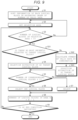
- FIG. 9 is a flowchart illustrating the procedure of the process of selecting the garbage collection target according to the second embodiment.
- step S 3 when the number of logical blocks not selected as the logical block of the garbage collection target in the selection area AR is greater than 0 (step S 3 : Yes), the process proceeds to step S 4 .
- step S 3 when the condition of step S 3 is satisfied, it is determined whether there is the most recently selected logical block of the garbage collection target, and the method for selecting the logical block is changed depending on a determination result thereof.
- step S 3 when the number of logical blocks not selected as the logical block of the garbage collection target in the selection area AR is greater than 0 (step S 3 : Yes), the data access unit 32 determines presence or absence of the selected logical block (step S 21 ), when there is no selected logical block (step S 21 : Yes), the process proceeds to step S 4 , and when there is the selected logical block (step S 21 : No), the process proceeds to step S 22 .
- step S 22 the data access unit 32 adds the number of valid data of each bank of the selected logical block to the number of valid data of each bank of the unselected logical block, thereby calculating the second read guide information.
- the data access unit 32 generates the second tabulation table 170 including the second read guide information (step S 22 ).
- the data access unit 32 refers to the second tabulation table 170 , compares pieces of the respective second read guide information of the logical blocks of the garbage collection target candidates in the selection area AR with each other, and selects the logical block of the garbage collection target (step S 23 ), and then the process proceeds to step S 5 .
- the memory system 100 calculates the second read guide information which is the maximum value as a result of adding the number of valid data for each bank in the logical block to the number of valid data for each bank of the logical block of the garbage collection target selected immediately before, and selects the logical block of the garbage collection target based on the calculated second read guide information.
- the memory system 100 selects the logical block of the garbage collection target based on the second read guide information also including the read time of each bank of the selected logical block. Accordingly, when reading a plurality of logical blocks 150 and performing the garbage collection, the memory system 100 can select the logical block 150 that requires a short read time in total among the plurality of logical blocks 150 .
- a third embodiment describes a method for selecting a logical block when the logical block is selected based on the second read guide information described in the second embodiment and there are a plurality of logical blocks having the same second read guide information.
- the data access unit 32 preferentially selects the logical block having the smaller number of erasure times of each logical block. In this case, selection schedule information indicating the next selection priority is attached to a logical block not selected, and when selecting the next logical block, the data access unit 32 selects the logical block to which the selection schedule information indicating the next selection priority is attached.
- FIG. 10 is a flowchart illustrating the procedure of the process of selecting the garbage collection target according to the third embodiment.
- step S 21 When it is determined whether there is the selected logical block and there is the selected logical block (step S 21 : No), it is determined whether there is the logical block to which the selection schedule information is attached, and when there is no logical block to which the selection schedule information is attached (step S 31 : Yes), the process proceeds to step S 22 .
- step S 31 when it is determined whether there is the logical block to which the selection schedule information is attached and there is the logical block to which the selection schedule information is attached (step S 31 : No), the data access unit 32 selects the logical block to which the selection schedule information is attached as the logical block of the garbage collection target (step S 32 ), and the process proceeds to step S 8 .
- the memory system 100 selects any one of the logical blocks 150 , and selects the others from the next time.
- the memory system 100 can consecutively select a plurality of logical blocks 150 having no difference in read time.
- the logical block 150 of the garbage collection target is selected by further using information on an access status of the bank of the logical block 150 .
- the data access unit 32 acquires the information on the access status. Next, the data access unit 32 refers to the information on the access status, extracts the logical block 150 having the valid data only in a bank not being read or written of the logical block 150 in the selection area AR, and extracts the logical block 150 having the least read guide information of the extracted logical block 150 .
- FIG. 11 is a flowchart illustrating the procedure of the process of selecting the garbage collection target according to the fourth embodiment.
- step S 4 the data access unit 32 acquires information on an access status (step S 61 ), refers to the information on the access status, extracts the logical block 150 having the valid data only in a bank not being read or written of the logical block 150 in the selection area AR, and extracts the logical block 150 having the least read guide information of the extracted logical block 150 (step S 62 ).
- the memory system 100 selects the logical block of the garbage collection target further based on the access information of the bank of the logical block 150 .
- the memory system 100 can select the logical block 150 of the garbage collection target depending on the access status to the bank of the logical block 150 .
- weighting is performed based on a type of a page to which the valid data of each bank belongs.
- Read time of the valid data page is different depending on whether the page is Lower, Middle, or Upper.
- the data access unit 32 generates the read guide information based on this point.
- the number of valid data for each bank in the second valid data management information is stored for each page type.
- the data access unit 32 acquires read reference time of each of Lower, Middle, and Upper. This reference time may be stored in the non-volatile memory 10 or may be stored by the data access unit 32 .
- the data access unit 32 calculates the read time of each bank of the logical block 150 by the following Equation (1).
- Read time of valid data of each bank number of valid data of Lower ⁇ reference time of Lower+number of valid data of Middle ⁇ reference time of Middle+number of valid data of Upper ⁇ reference time of Upper (Equation 1)
- the data access unit 32 uses a maximum value of the read time of each bank as the read guide information for each of the logical blocks.
- FIG. 12 is a flowchart illustrating the procedure of the process of selecting the garbage collection target according to the fifth embodiment.
- step S 4 the data access unit 32 selects the logical block 150 of the garbage collection target based on the read guide information by the read time of the valid data of each bank of the logical block 150 according to the Equation (1) (step S 71 ).
- the memory system 100 calculates the read time in accordance with the page type of the valid data, and generates the read guide information based on the read time, thereby making it possible to calculate an appropriate read time in accordance with the page type. Accordingly, the memory system 100 can appropriately select the logical block 150 of the garbage collection target by using the read guide information based on the read time.
Abstract
Description
Read time of valid data of each bank=number of valid data of Lower×reference time of Lower+number of valid data of Middle×reference time of Middle+number of valid data of Upper×reference time of Upper (Equation 1)
Claims (11)
Applications Claiming Priority (2)
| Application Number | Priority Date | Filing Date | Title |
|---|---|---|---|
| JP2021-152897 | 2021-09-21 | ||
| JP2021152897A JP2023044824A (en) | 2021-09-21 | 2021-09-21 | memory system |
Publications (2)
| Publication Number | Publication Date |
|---|---|
| US20230089083A1 US20230089083A1 (en) | 2023-03-23 |
| US11899573B2 true US11899573B2 (en) | 2024-02-13 |
Family
ID=85572862
Family Applications (1)
| Application Number | Title | Priority Date | Filing Date |
|---|---|---|---|
| US17/684,576 Active 2042-04-26 US11899573B2 (en) | 2021-09-21 | 2022-03-02 | Memory system |
Country Status (2)
| Country | Link |
|---|---|
| US (1) | US11899573B2 (en) |
| JP (1) | JP2023044824A (en) |
Citations (8)
| Publication number | Priority date | Publication date | Assignee | Title |
|---|---|---|---|---|
| US20090271562A1 (en) * | 2008-04-25 | 2009-10-29 | Sinclair Alan W | Method and system for storage address re-mapping for a multi-bank memory device |
| US20120311235A1 (en) | 2011-05-30 | 2012-12-06 | Kabushiki Kaisha Toshiba | Memory system having multiple channels and method of generating read commands for compaction in memory system |
| JP2013030081A (en) | 2011-07-29 | 2013-02-07 | Toshiba Corp | Data storage device, memory controller and memory control method |
| US20150212937A1 (en) | 2012-09-06 | 2015-07-30 | Pi-Coral, Inc. | Storage translation layer |
| US20160011971A1 (en) | 2014-07-14 | 2016-01-14 | Jae-Il Lee | Storage medium, memory system, and method of managing storage area in memory system |
| TWI679534B (en) * | 2017-09-18 | 2019-12-11 | 慧榮科技股份有限公司 | Data storage device and data storage method |
| US10620958B1 (en) * | 2018-12-03 | 2020-04-14 | Advanced Micro Devices, Inc. | Crossbar between clients and a cache |
| US10963160B2 (en) | 2018-08-14 | 2021-03-30 | SK Hynix Inc. | Apparatus and method for checking valid data in block capable of storing large volume data in memory system |
-
2021
- 2021-09-21 JP JP2021152897A patent/JP2023044824A/en active Pending
-
2022
- 2022-03-02 US US17/684,576 patent/US11899573B2/en active Active
Patent Citations (9)
| Publication number | Priority date | Publication date | Assignee | Title |
|---|---|---|---|---|
| US20090271562A1 (en) * | 2008-04-25 | 2009-10-29 | Sinclair Alan W | Method and system for storage address re-mapping for a multi-bank memory device |
| US20120311235A1 (en) | 2011-05-30 | 2012-12-06 | Kabushiki Kaisha Toshiba | Memory system having multiple channels and method of generating read commands for compaction in memory system |
| JP2012248109A (en) | 2011-05-30 | 2012-12-13 | Toshiba Corp | Memory unit having multiple channels and read command group generating method for compaction in the memory unit |
| JP2013030081A (en) | 2011-07-29 | 2013-02-07 | Toshiba Corp | Data storage device, memory controller and memory control method |
| US20150212937A1 (en) | 2012-09-06 | 2015-07-30 | Pi-Coral, Inc. | Storage translation layer |
| US20160011971A1 (en) | 2014-07-14 | 2016-01-14 | Jae-Il Lee | Storage medium, memory system, and method of managing storage area in memory system |
| TWI679534B (en) * | 2017-09-18 | 2019-12-11 | 慧榮科技股份有限公司 | Data storage device and data storage method |
| US10963160B2 (en) | 2018-08-14 | 2021-03-30 | SK Hynix Inc. | Apparatus and method for checking valid data in block capable of storing large volume data in memory system |
| US10620958B1 (en) * | 2018-12-03 | 2020-04-14 | Advanced Micro Devices, Inc. | Crossbar between clients and a cache |
Also Published As
| Publication number | Publication date |
|---|---|
| JP2023044824A (en) | 2023-04-03 |
| US20230089083A1 (en) | 2023-03-23 |
Similar Documents
| Publication | Publication Date | Title |
|---|---|---|
| TWI678619B (en) | Memory devices including dynamic superblocks, and related methods and electronic systems | |
| US9189389B2 (en) | Memory controller and memory system | |
| KR100977899B1 (en) | Method and apparatus for effectively enabling an out of sequence write process within a non-volatile memory system | |
| TWI514260B (en) | Data storage device and method for managing blocks of a flash memory | |
| US20130227246A1 (en) | Management information generating method, logical block constructing method, and semiconductor memory device | |
| US9582224B2 (en) | Memory control circuit unit, memory storage apparatus and data accessing method | |
| US9965194B2 (en) | Data writing method, memory control circuit unit and memory storage apparatus which performs data arrangement operation according to usage frequency of physical erasing unit of memory storage apparatus | |
| CN102915208A (en) | Information processing apparatus, semiconductor memory device and control method for the semiconductor memory device | |
| US11163694B2 (en) | Memory control method, memory storage device and memory control circuit unit | |
| US9009442B2 (en) | Data writing method, memory controller and memory storage apparatus | |
| US11175847B2 (en) | Data merging method, control circuit unit and storage device for flash memory | |
| US10289546B2 (en) | Memory management method, memory control circuit unit and memory storage device | |
| US20150339069A1 (en) | Memory system and method | |
| US20140089566A1 (en) | Data storing method, and memory controller and memory storage apparatus using the same | |
| US9778862B2 (en) | Data storing method for preventing data losing during flush operation, memory control circuit unit and memory storage apparatus | |
| US10007601B2 (en) | Data storage device and operating method for flash memory | |
| US11899573B2 (en) | Memory system | |
| JP6100927B2 (en) | Information processing device | |
| JP5687649B2 (en) | Method for controlling semiconductor memory device | |
| US9710374B2 (en) | Data writing method, memory controller and memory storage device | |
| US11307982B2 (en) | Memory management method with a data merging process based on risk physical units and distribution counts, memory storage device and memory control circuit unit | |
| US11023170B2 (en) | Writing method for multi-stream write solid state drive | |
| JP4661566B2 (en) | Access controller, flash memory system, and access control method | |
| US9268685B2 (en) | Memory system and constructing method of virtual block | |
| US20220350485A1 (en) | Memory system and method for controlling memory system |
Legal Events
| Date | Code | Title | Description |
|---|---|---|---|
| FEPP | Fee payment procedure |
Free format text: ENTITY STATUS SET TO UNDISCOUNTED (ORIGINAL EVENT CODE: BIG.); ENTITY STATUS OF PATENT OWNER: LARGE ENTITY |
|
| STPP | Information on status: patent application and granting procedure in general |
Free format text: DOCKETED NEW CASE - READY FOR EXAMINATION |
|
| AS | Assignment |
Owner name: KIOXIA CORPORATION, JAPAN Free format text: ASSIGNMENT OF ASSIGNORS INTEREST;ASSIGNORS:NISHINO, REINA;SUNATA, TETSUYA;FUJIMORI, TAKUMI;SIGNING DATES FROM 20220419 TO 20220624;REEL/FRAME:060350/0875 |
|
| STPP | Information on status: patent application and granting procedure in general |
Free format text: NON FINAL ACTION MAILED |
|
| STPP | Information on status: patent application and granting procedure in general |
Free format text: RESPONSE TO NON-FINAL OFFICE ACTION ENTERED AND FORWARDED TO EXAMINER |
|
| STPP | Information on status: patent application and granting procedure in general |
Free format text: NOTICE OF ALLOWANCE MAILED -- APPLICATION RECEIVED IN OFFICE OF PUBLICATIONS |
|
| STPP | Information on status: patent application and granting procedure in general |
Free format text: PUBLICATIONS -- ISSUE FEE PAYMENT RECEIVED |
|
| STPP | Information on status: patent application and granting procedure in general |
Free format text: PUBLICATIONS -- ISSUE FEE PAYMENT VERIFIED |
|
| STCF | Information on status: patent grant |
Free format text: PATENTED CASE |