US11898237B2 - Device and method for removing coating material from openings in a part - Google Patents
Device and method for removing coating material from openings in a part Download PDFInfo
- Publication number
- US11898237B2 US11898237B2 US17/251,782 US201917251782A US11898237B2 US 11898237 B2 US11898237 B2 US 11898237B2 US 201917251782 A US201917251782 A US 201917251782A US 11898237 B2 US11898237 B2 US 11898237B2
- Authority
- US
- United States
- Prior art keywords
- component
- region
- cooling fluid
- reference point
- fluid opening
- Prior art date
- Legal status (The legal status is an assumption and is not a legal conclusion. Google has not performed a legal analysis and makes no representation as to the accuracy of the status listed.)
- Active, expires
Links
- 238000000576 coating method Methods 0.000 title claims abstract description 72
- 239000011248 coating agent Substances 0.000 title claims abstract description 65
- 238000000034 method Methods 0.000 title claims abstract description 61
- 239000000463 material Substances 0.000 title claims abstract description 46
- 239000012809 cooling fluid Substances 0.000 claims abstract description 130
- 230000008569 process Effects 0.000 claims description 56
- 238000001514 detection method Methods 0.000 claims description 21
- 238000010276 construction Methods 0.000 claims description 12
- 238000004519 manufacturing process Methods 0.000 claims description 9
- 239000000470 constituent Substances 0.000 claims description 6
- 239000012530 fluid Substances 0.000 claims description 6
- 230000008901 benefit Effects 0.000 description 15
- 238000001816 cooling Methods 0.000 description 10
- 239000010410 layer Substances 0.000 description 10
- 238000009419 refurbishment Methods 0.000 description 9
- PXHVJJICTQNCMI-UHFFFAOYSA-N Nickel Chemical compound [Ni] PXHVJJICTQNCMI-UHFFFAOYSA-N 0.000 description 7
- 239000012720 thermal barrier coating Substances 0.000 description 6
- 238000003860 storage Methods 0.000 description 5
- 239000013078 crystal Substances 0.000 description 4
- 229910000601 superalloy Inorganic materials 0.000 description 4
- 229910017052 cobalt Inorganic materials 0.000 description 3
- 239000010941 cobalt Substances 0.000 description 3
- GUTLYIVDDKVIGB-UHFFFAOYSA-N cobalt atom Chemical compound [Co] GUTLYIVDDKVIGB-UHFFFAOYSA-N 0.000 description 3
- 230000000873 masking effect Effects 0.000 description 3
- 238000005259 measurement Methods 0.000 description 3
- 238000000691 measurement method Methods 0.000 description 3
- 229910052759 nickel Inorganic materials 0.000 description 3
- 230000003647 oxidation Effects 0.000 description 3
- 238000007254 oxidation reaction Methods 0.000 description 3
- 230000008439 repair process Effects 0.000 description 3
- MCMNRKCIXSYSNV-UHFFFAOYSA-N Zirconium dioxide Chemical compound O=[Zr]=O MCMNRKCIXSYSNV-UHFFFAOYSA-N 0.000 description 2
- 229910045601 alloy Inorganic materials 0.000 description 2
- 239000000956 alloy Substances 0.000 description 2
- 238000012937 correction Methods 0.000 description 2
- 230000007797 corrosion Effects 0.000 description 2
- 238000005260 corrosion Methods 0.000 description 2
- 238000010586 diagram Methods 0.000 description 2
- 230000001771 impaired effect Effects 0.000 description 2
- 238000012545 processing Methods 0.000 description 2
- 239000011241 protective layer Substances 0.000 description 2
- 238000009418 renovation Methods 0.000 description 2
- 238000007711 solidification Methods 0.000 description 2
- 230000008023 solidification Effects 0.000 description 2
- 238000012546 transfer Methods 0.000 description 2
- YPFNIPKMNMDDDB-UHFFFAOYSA-K 2-[2-[bis(carboxylatomethyl)amino]ethyl-(2-hydroxyethyl)amino]acetate;iron(3+) Chemical compound [Fe+3].OCCN(CC([O-])=O)CCN(CC([O-])=O)CC([O-])=O YPFNIPKMNMDDDB-UHFFFAOYSA-K 0.000 description 1
- 241000191291 Abies alba Species 0.000 description 1
- 241000196324 Embryophyta Species 0.000 description 1
- 238000012369 In process control Methods 0.000 description 1
- XEEYBQQBJWHFJM-UHFFFAOYSA-N Iron Chemical compound [Fe] XEEYBQQBJWHFJM-UHFFFAOYSA-N 0.000 description 1
- 229910009474 Y2O3—ZrO2 Inorganic materials 0.000 description 1
- 230000006978 adaptation Effects 0.000 description 1
- BRPQOXSCLDDYGP-UHFFFAOYSA-N calcium oxide Chemical compound [O-2].[Ca+2] BRPQOXSCLDDYGP-UHFFFAOYSA-N 0.000 description 1
- 239000000292 calcium oxide Substances 0.000 description 1
- ODINCKMPIJJUCX-UHFFFAOYSA-N calcium oxide Inorganic materials [Ca]=O ODINCKMPIJJUCX-UHFFFAOYSA-N 0.000 description 1
- 238000005266 casting Methods 0.000 description 1
- 230000008859 change Effects 0.000 description 1
- 238000012512 characterization method Methods 0.000 description 1
- 230000007812 deficiency Effects 0.000 description 1
- 230000001419 dependent effect Effects 0.000 description 1
- 238000010894 electron beam technology Methods 0.000 description 1
- 229910052735 hafnium Inorganic materials 0.000 description 1
- VBJZVLUMGGDVMO-UHFFFAOYSA-N hafnium atom Chemical compound [Hf] VBJZVLUMGGDVMO-UHFFFAOYSA-N 0.000 description 1
- 230000006872 improvement Effects 0.000 description 1
- 238000010965 in-process control Methods 0.000 description 1
- 230000002401 inhibitory effect Effects 0.000 description 1
- 238000005305 interferometry Methods 0.000 description 1
- 239000007788 liquid Substances 0.000 description 1
- 239000000395 magnesium oxide Substances 0.000 description 1
- CPLXHLVBOLITMK-UHFFFAOYSA-N magnesium oxide Inorganic materials [Mg]=O CPLXHLVBOLITMK-UHFFFAOYSA-N 0.000 description 1
- AXZKOIWUVFPNLO-UHFFFAOYSA-N magnesium;oxygen(2-) Chemical compound [O-2].[Mg+2] AXZKOIWUVFPNLO-UHFFFAOYSA-N 0.000 description 1
- 238000012423 maintenance Methods 0.000 description 1
- 239000000155 melt Substances 0.000 description 1
- 229910001092 metal group alloy Inorganic materials 0.000 description 1
- 238000010327 methods by industry Methods 0.000 description 1
- 239000000203 mixture Substances 0.000 description 1
- 230000004048 modification Effects 0.000 description 1
- 238000012986 modification Methods 0.000 description 1
- TWNQGVIAIRXVLR-UHFFFAOYSA-N oxo(oxoalumanyloxy)alumane Chemical compound O=[Al]O[Al]=O TWNQGVIAIRXVLR-UHFFFAOYSA-N 0.000 description 1
- SIWVEOZUMHYXCS-UHFFFAOYSA-N oxo(oxoyttriooxy)yttrium Chemical compound O=[Y]O[Y]=O SIWVEOZUMHYXCS-UHFFFAOYSA-N 0.000 description 1
- 230000036961 partial effect Effects 0.000 description 1
- 238000007750 plasma spraying Methods 0.000 description 1
- 238000002360 preparation method Methods 0.000 description 1
- 239000011253 protective coating Substances 0.000 description 1
- 230000001681 protective effect Effects 0.000 description 1
- 230000002441 reversible effect Effects 0.000 description 1
- 238000005488 sandblasting Methods 0.000 description 1
- 230000035939 shock Effects 0.000 description 1
- 229910052710 silicon Inorganic materials 0.000 description 1
- 239000010703 silicon Substances 0.000 description 1
- 239000007787 solid Substances 0.000 description 1
- 230000007704 transition Effects 0.000 description 1
- 238000009834 vaporization Methods 0.000 description 1
- 230000008016 vaporization Effects 0.000 description 1
- 229910052727 yttrium Inorganic materials 0.000 description 1
- VWQVUPCCIRVNHF-UHFFFAOYSA-N yttrium atom Chemical compound [Y] VWQVUPCCIRVNHF-UHFFFAOYSA-N 0.000 description 1
Images

Classifications
-
- C—CHEMISTRY; METALLURGY
- C23—COATING METALLIC MATERIAL; COATING MATERIAL WITH METALLIC MATERIAL; CHEMICAL SURFACE TREATMENT; DIFFUSION TREATMENT OF METALLIC MATERIAL; COATING BY VACUUM EVAPORATION, BY SPUTTERING, BY ION IMPLANTATION OR BY CHEMICAL VAPOUR DEPOSITION, IN GENERAL; INHIBITING CORROSION OF METALLIC MATERIAL OR INCRUSTATION IN GENERAL
- C23C—COATING METALLIC MATERIAL; COATING MATERIAL WITH METALLIC MATERIAL; SURFACE TREATMENT OF METALLIC MATERIAL BY DIFFUSION INTO THE SURFACE, BY CHEMICAL CONVERSION OR SUBSTITUTION; COATING BY VACUUM EVAPORATION, BY SPUTTERING, BY ION IMPLANTATION OR BY CHEMICAL VAPOUR DEPOSITION, IN GENERAL
- C23C14/00—Coating by vacuum evaporation, by sputtering or by ion implantation of the coating forming material
- C23C14/22—Coating by vacuum evaporation, by sputtering or by ion implantation of the coating forming material characterised by the process of coating
- C23C14/54—Controlling or regulating the coating process
-
- B—PERFORMING OPERATIONS; TRANSPORTING
- B23—MACHINE TOOLS; METAL-WORKING NOT OTHERWISE PROVIDED FOR
- B23P—METAL-WORKING NOT OTHERWISE PROVIDED FOR; COMBINED OPERATIONS; UNIVERSAL MACHINE TOOLS
- B23P6/00—Restoring or reconditioning objects
- B23P6/002—Repairing turbine components, e.g. moving or stationary blades, rotors
- B23P6/007—Repairing turbine components, e.g. moving or stationary blades, rotors using only additive methods, e.g. build-up welding
-
- C—CHEMISTRY; METALLURGY
- C23—COATING METALLIC MATERIAL; COATING MATERIAL WITH METALLIC MATERIAL; CHEMICAL SURFACE TREATMENT; DIFFUSION TREATMENT OF METALLIC MATERIAL; COATING BY VACUUM EVAPORATION, BY SPUTTERING, BY ION IMPLANTATION OR BY CHEMICAL VAPOUR DEPOSITION, IN GENERAL; INHIBITING CORROSION OF METALLIC MATERIAL OR INCRUSTATION IN GENERAL
- C23C—COATING METALLIC MATERIAL; COATING MATERIAL WITH METALLIC MATERIAL; SURFACE TREATMENT OF METALLIC MATERIAL BY DIFFUSION INTO THE SURFACE, BY CHEMICAL CONVERSION OR SUBSTITUTION; COATING BY VACUUM EVAPORATION, BY SPUTTERING, BY ION IMPLANTATION OR BY CHEMICAL VAPOUR DEPOSITION, IN GENERAL
- C23C14/00—Coating by vacuum evaporation, by sputtering or by ion implantation of the coating forming material
- C23C14/04—Coating on selected surface areas, e.g. using masks
-
- C—CHEMISTRY; METALLURGY
- C23—COATING METALLIC MATERIAL; COATING MATERIAL WITH METALLIC MATERIAL; CHEMICAL SURFACE TREATMENT; DIFFUSION TREATMENT OF METALLIC MATERIAL; COATING BY VACUUM EVAPORATION, BY SPUTTERING, BY ION IMPLANTATION OR BY CHEMICAL VAPOUR DEPOSITION, IN GENERAL; INHIBITING CORROSION OF METALLIC MATERIAL OR INCRUSTATION IN GENERAL
- C23C—COATING METALLIC MATERIAL; COATING MATERIAL WITH METALLIC MATERIAL; SURFACE TREATMENT OF METALLIC MATERIAL BY DIFFUSION INTO THE SURFACE, BY CHEMICAL CONVERSION OR SUBSTITUTION; COATING BY VACUUM EVAPORATION, BY SPUTTERING, BY ION IMPLANTATION OR BY CHEMICAL VAPOUR DEPOSITION, IN GENERAL
- C23C14/00—Coating by vacuum evaporation, by sputtering or by ion implantation of the coating forming material
- C23C14/22—Coating by vacuum evaporation, by sputtering or by ion implantation of the coating forming material characterised by the process of coating
- C23C14/24—Vacuum evaporation
- C23C14/28—Vacuum evaporation by wave energy or particle radiation
- C23C14/30—Vacuum evaporation by wave energy or particle radiation by electron bombardment
-
- C—CHEMISTRY; METALLURGY
- C23—COATING METALLIC MATERIAL; COATING MATERIAL WITH METALLIC MATERIAL; CHEMICAL SURFACE TREATMENT; DIFFUSION TREATMENT OF METALLIC MATERIAL; COATING BY VACUUM EVAPORATION, BY SPUTTERING, BY ION IMPLANTATION OR BY CHEMICAL VAPOUR DEPOSITION, IN GENERAL; INHIBITING CORROSION OF METALLIC MATERIAL OR INCRUSTATION IN GENERAL
- C23C—COATING METALLIC MATERIAL; COATING MATERIAL WITH METALLIC MATERIAL; SURFACE TREATMENT OF METALLIC MATERIAL BY DIFFUSION INTO THE SURFACE, BY CHEMICAL CONVERSION OR SUBSTITUTION; COATING BY VACUUM EVAPORATION, BY SPUTTERING, BY ION IMPLANTATION OR BY CHEMICAL VAPOUR DEPOSITION, IN GENERAL
- C23C14/00—Coating by vacuum evaporation, by sputtering or by ion implantation of the coating forming material
- C23C14/58—After-treatment
- C23C14/5873—Removal of material
-
- C—CHEMISTRY; METALLURGY
- C23—COATING METALLIC MATERIAL; COATING MATERIAL WITH METALLIC MATERIAL; CHEMICAL SURFACE TREATMENT; DIFFUSION TREATMENT OF METALLIC MATERIAL; COATING BY VACUUM EVAPORATION, BY SPUTTERING, BY ION IMPLANTATION OR BY CHEMICAL VAPOUR DEPOSITION, IN GENERAL; INHIBITING CORROSION OF METALLIC MATERIAL OR INCRUSTATION IN GENERAL
- C23C—COATING METALLIC MATERIAL; COATING MATERIAL WITH METALLIC MATERIAL; SURFACE TREATMENT OF METALLIC MATERIAL BY DIFFUSION INTO THE SURFACE, BY CHEMICAL CONVERSION OR SUBSTITUTION; COATING BY VACUUM EVAPORATION, BY SPUTTERING, BY ION IMPLANTATION OR BY CHEMICAL VAPOUR DEPOSITION, IN GENERAL
- C23C4/00—Coating by spraying the coating material in the molten state, e.g. by flame, plasma or electric discharge
- C23C4/01—Selective coating, e.g. pattern coating, without pre-treatment of the material to be coated
-
- C—CHEMISTRY; METALLURGY
- C23—COATING METALLIC MATERIAL; COATING MATERIAL WITH METALLIC MATERIAL; CHEMICAL SURFACE TREATMENT; DIFFUSION TREATMENT OF METALLIC MATERIAL; COATING BY VACUUM EVAPORATION, BY SPUTTERING, BY ION IMPLANTATION OR BY CHEMICAL VAPOUR DEPOSITION, IN GENERAL; INHIBITING CORROSION OF METALLIC MATERIAL OR INCRUSTATION IN GENERAL
- C23C—COATING METALLIC MATERIAL; COATING MATERIAL WITH METALLIC MATERIAL; SURFACE TREATMENT OF METALLIC MATERIAL BY DIFFUSION INTO THE SURFACE, BY CHEMICAL CONVERSION OR SUBSTITUTION; COATING BY VACUUM EVAPORATION, BY SPUTTERING, BY ION IMPLANTATION OR BY CHEMICAL VAPOUR DEPOSITION, IN GENERAL
- C23C4/00—Coating by spraying the coating material in the molten state, e.g. by flame, plasma or electric discharge
- C23C4/12—Coating by spraying the coating material in the molten state, e.g. by flame, plasma or electric discharge characterised by the method of spraying
- C23C4/134—Plasma spraying
-
- C—CHEMISTRY; METALLURGY
- C23—COATING METALLIC MATERIAL; COATING MATERIAL WITH METALLIC MATERIAL; CHEMICAL SURFACE TREATMENT; DIFFUSION TREATMENT OF METALLIC MATERIAL; COATING BY VACUUM EVAPORATION, BY SPUTTERING, BY ION IMPLANTATION OR BY CHEMICAL VAPOUR DEPOSITION, IN GENERAL; INHIBITING CORROSION OF METALLIC MATERIAL OR INCRUSTATION IN GENERAL
- C23C—COATING METALLIC MATERIAL; COATING MATERIAL WITH METALLIC MATERIAL; SURFACE TREATMENT OF METALLIC MATERIAL BY DIFFUSION INTO THE SURFACE, BY CHEMICAL CONVERSION OR SUBSTITUTION; COATING BY VACUUM EVAPORATION, BY SPUTTERING, BY ION IMPLANTATION OR BY CHEMICAL VAPOUR DEPOSITION, IN GENERAL
- C23C4/00—Coating by spraying the coating material in the molten state, e.g. by flame, plasma or electric discharge
- C23C4/18—After-treatment
-
- F—MECHANICAL ENGINEERING; LIGHTING; HEATING; WEAPONS; BLASTING
- F01—MACHINES OR ENGINES IN GENERAL; ENGINE PLANTS IN GENERAL; STEAM ENGINES
- F01D—NON-POSITIVE DISPLACEMENT MACHINES OR ENGINES, e.g. STEAM TURBINES
- F01D5/00—Blades; Blade-carrying members; Heating, heat-insulating, cooling or antivibration means on the blades or the members
- F01D5/005—Repairing methods or devices
-
- B—PERFORMING OPERATIONS; TRANSPORTING
- B23—MACHINE TOOLS; METAL-WORKING NOT OTHERWISE PROVIDED FOR
- B23P—METAL-WORKING NOT OTHERWISE PROVIDED FOR; COMBINED OPERATIONS; UNIVERSAL MACHINE TOOLS
- B23P2700/00—Indexing scheme relating to the articles being treated, e.g. manufactured, repaired, assembled, connected or other operations covered in the subgroups
- B23P2700/06—Cooling passages of turbine components, e.g. unblocking or preventing blocking of cooling passages of turbine components
Definitions
- the present invention relates to a process for removing coating material from the cooling fluid openings of a component.
- the invention further relates to an apparatus which can be used in the process of the invention.
- the present invention further relates to the use of the process of the invention and the apparatus of the invention in the production or refurbishment of a component.
- the cooling air holes are at least partially closed by the coating material. For this reason, they have to be opened again after conclusion of the coating process. This can occur by, for example, particular cooling air holes being selected as reference holes and then being closed by means of a masking material to which the coating material does not adhere readily before the coating process. After coating, the masking material in the reference holes is then either manually removed or burnt out in the event of a masking material which can be burnt out being employed. The position of the remaining holes is subsequently determined with the aid of the position of the reference holes. The further holes are subsequently opened again, for example by means of a laser program.
- the invention provides a process for coating a component, where the component has a first region and a second region, where the first region comprises at least one cooling fluid opening having an adjoining cooling fluid channel and where the first region is to be coated with a coating material which is not to be applied in the second region, wherein the process comprises the following steps:
- a reference point can represent a characteristic structure on the component or the shape of the surface of the component, which are detected by means of a measuring device.
- the at least one reference point can, for example, also be detected mechanically. For example, this can be effected by contacting a specific position in the second region of the component. This is particularly advantageous since exact information in respect of the reference point, for example the position thereof in the internal coordinate system of the apparatus utilized for this purpose, can be obtained highly precisely and reliably by means of simple known methods.
- the reference point here can, for example, also be brought into contact by means of a constituent of the apparatus and thus be moved into a particular position.
- the invention provides an apparatus for opening cooling fluid openings of a coated component, where the component has a first region and a second region, where the first region comprises at least one cooling fluid opening having an adjoining cooling fluid channel and where the first region has been coated with a coating material which has not been applied in the second region, wherein the apparatus comprises at least one detection device, at least one holding device and at least one instrument for removing coating material in the region of the cooling fluid openings, where the holding device is suitable for providing either direct or indirect, detachable fastening to the second region of the component, where the at least one detection device is suitable for detecting at least one reference point in the second region in order to determine the position of the at least one reference point and/or adapt the position of the component on the basis of the reference point, where the instrument for removing the coating material in the region of the cooling fluid openings is suitable for removing the coating material in a targeted manner from the cooling fluid openings on the basis of the position of the component determined by means of the detection device and/or the adapted position of the
- the invention provides for the use of the process of the invention and/or an apparatus of the invention in the production or refurbishment of a component of a turbo machine comprising a fluid stream, wherein the component comprises a first region and a second region, where the first region of the component is provided with a coating and is suitable for being exposed to the fluid stream of the turbo machine.
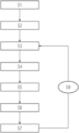
- FIG. 1 shows a flow diagram of the process of the invention.
- the first apparatus is an apparatus like the second apparatus or the first apparatus is identical to the second apparatus. Owing to the possibility of carrying out the process of the invention using a very simply constructed apparatus, the procurement price of the corresponding apparatus is very low. This allows an apparatus as is utilized in step F) also to be used economically feasibly for step B), even when constituents thereof are not necessary for step B). This offers advantages for the process since, for example, no adaptation to another reference system/coordinate system of another plant has to be carried out.
- the at least one cooling fluid opening in the first region of the component serves as reference opening in step B), by means of which the position of at least one further cooling fluid opening in the first region of the component is derived.
- the mechanical detection of the reference point is surprisingly particularly advantageous.
- the reliability, speed and accuracy are particularly good here.
- detection of the at least one reference point is therefore advantageously carried out by touching the reference point.
- the mechanical detection can be carried out here using a 6 point nest in the second region of the component.
- the at least one reference point comprises at least one 6-point nest.
- orientation of the component can be effected by means of detection of the at least one reference point.
- the orientation of the component can be improved so that the instrument for removing the coating material in the region of the cooling fluid openings can be used with an improved angle with the assistance of the construction data.
- an improved quality of the cooling fluid openings ultimately obtained and thus also the flows of the cooling fluid conveyed through the cooling fluid channel can be achieved in this way.
- orientation of the component in the first apparatus and/or the second apparatus in step B) and/or F) is effected on the basis of the detection of the at least one reference point in the respective step.
- a corresponding orientation is advantageously effected in step F).
- the direct, detachable fastening of the component in the first apparatus and/or the second apparatus is achieved by means of a holding device which is a constituent of the first apparatus and/or the second apparatus and contacts the surface of the second region of the component
- the indirect, detachable fastening of the component is achieved by means of a holding device which is temporarily connected to the first apparatus and/or second apparatus and contacts the second region of the component.
- Advantage is typically given to the holding device used for the abovementioned indirect, detachable fastening being connected to the apparatus such as the first apparatus and/or second apparatus only for the time of the process of the invention.
- the component is fastened to the holding device which is in turn temporarily fixed, in particular, in the apparatus of the invention. At least a basic position and orientation of the component is typically maintained thereby even when the component is temporarily removed from the apparatus in between.
- step B) the data obtained in step B) are therefore advantageously corrected by means of fitting processes.
- corrections to the shape of the at least one reference point and the at least one cooling fluid opening are made here in order to correct, for example, a deviation from the ideal shape as a result of damage. This allows, for example, an exact determination of the intended position of the cooling fluid opening even in the case of damage to one side of the at least one cooling fluid opening.
- step B it has typically been found to be advantageous to utilize data obtained in step B) in order to produce a data set concerning the relative position of the at least one cooling fluid opening relative to the at least one reference point.
- simple transfer of the data to another apparatus can be carried out thereby.
- the relative position of the at least one cooling fluid opening in the first region of the component relative to the at least one reference point in the second region of the component is therefore advantageously determined from the data obtained in step B).
- the relative position of the at least one cooling fluid opening can be utilized to calculate, on the basis of the absolute position of the at least one reference point in step F), the absolute position of the at least one cooling fluid opening in this step, even when this opening is covered by the coating.
- the process indicates a relative position of the at least one cooling fluid opening relative to the at least one reference point and an absolute position in the first apparatus in step B) and in the second apparatus in step F), and the absolute position of the at least one cooling fluid opening is therefore advantageously determined in step F) on the basis of the relative position of the at least one cooling fluid opening in step B) and detection of the at least one reference point in step F), and the removal of the coating material in step F) is carried out on the basis of the absolute position of the at least one cooling fluid opening.
- the position of further cooling fluid openings is determined, for example, with the aid of available construction data such as CAD data, with the cooling fluid opening whose position has actually been determined serving as reference point.
- the position of further cooling fluid openings has surprisingly been able to be determined sufficiently accurately in this way, with no excessive deviations from the actual position occurring for typical applications. This allows a significant speeding up of the process without the extremely high precision of the correct process being appreciably impaired.
- the position of at least one further cooling fluid opening in the first region of the component is determined from the position of the at least one cooling fluid opening in the first region of the component obtained by means of the measuring device and the relative position of the at least one further cooling fluid opening on the basis of construction data, for example CAD data.
- one or more cooling fluid openings can be selected from among the interpolated cooling fluid openings either manually or automatically and the position thereof can likewise be determined in the measurement method in step B).
- the position of at least one additional cooling fluid opening in the first region of the component is therefore advantageously measured in step B) in order to compare a position of a cooling fluid opening in the first region of the component which has been interpolated by means of the construction data with actual measured data, either manually or automatically, advantageously automatically.
- the speed of the process can be significantly increased by skillful selection of the interpolated and actually measured cooling fluid openings, but without the accuracy being appreciably impaired thereby.
- the rows comprise at least 5 cooling fluid openings and the position of at least one, advantageously two, of the cooling fluid openings in the respective row is determined.
- the cooling fluid openings in the first region of the component are at least partly arranged in the form of rows comprising at least 5 cooling fluid openings and at least the position of the first, advantageously of the first and the last, cooling fluid opening of the rows is determined by means of the measuring device of the first apparatus in step B).
- step B an improved quality in the determination of the position of the at least one cooling fluid opening is typically achieved when the coating to be removed in the first region of the component is removed before step B).
- the removal of the coating in the first region of the component is therefore advantageously carried out before step B) in the case of refurbishment.
- the optional step C) is typically omitted here, as long as it is not found that further residues of coating are present and have to be removed.
- step B) in respect of the position of the at least one cooling fluid opening are checked in respect of usability and the position of at least one further cooling fluid opening is determined if necessary.
- the at least one cooling fluid opening is to serve as reference point to obtain, by means of interpolation, the exact position of the further cooling fluid opening on the basis of, for example, construction data, it has been found to be advantageous to check the measured data obtained for the at least one cooling fluid opening. If, for example, the exact position of the cooling fluid opening concerned is not able to be determined sufficiently accurately because of damage, it has been found to be advantageous for an alternative reference opening to be determined in this case.
- first apparatus in step B) and the second apparatus in step F) have the same coordinate system. This significantly assists transfer of the data obtained.
- the first apparatus and the second apparatus advantageously have the identical coordinate system
- the first apparatus in step B) and the second apparatus in step F) are more advantageously apparatuses of the same construction type and are even more advantageously identical apparatuses.
- advantage is given to the fastening of the component at least in the apparatus in step F) being movable in such a way as to reverse changes in the position of the component between step B) and F) relative to the coordinate system of the apparatus.
- step B It has typically also been found to be advantageous to store the data obtained by means of the first apparatus in step B).
- storage can be effected on a transportable storage medium or in a storage unit integrated into a network.
- the transportable storage unit can subsequently be, for example for step F), connected to the second apparatus or the data obtained in step B) can be retrieved via a network connection from the storage unit integrated into the network.
- the process of the invention has been found to be particularly advantageous for the production and refurbishment of components of a turbo machine.
- reopening of the closed cooling fluid openings can be carried out with the required high precision and nevertheless with great speed by this means.
- the component is therefore advantageously a constituent of a turbo machine and the first region of the component is suitable for being exposed to the fluid stream of the turbo machine.
- the component can in principle be, in particular, any component of turbo machines which is provided with cooling fluid openings.
- the cooling fluid openings typically serve as film cooling openings for cooling and protecting the corresponding component.
- the component is therefore advantageously a blade or a heat shield. For example, it is a guide vane or rotor blade.
- Such guide vanes and rotor blades are employed, for example, in the turbine unit of steam turbines and gas turbines as examples of turbo machines or else in the compressor unit of turbo machines as examples of turbo machines.
- the component is therefore advantageously selected from the group consisting of heat shields, guide vanes and rotor blades of a turbine and guide vanes and rotor blades of a compressor.
- Such components are typically made at least partly of alloys which are resistant to high temperatures, for example iron-, nickel- or cobalt-based superalloys.
- superalloys are known, for example, from EP 1 204 776 B1, EP 1 306 454, EP 1 319 729 A1, WO 99/67435 or WO 00/44949.
- nickel superalloys are frequently used since they are advantageous for many applications.
- Advantage is also given to the corresponding components being monocrystalline (SX structure).
- the manufacture of such monocrystalline workpieces is carried out by, for example, directional solidification from the melt. These are casting processes in which the liquid metallic alloy solidifies to give a monocrystalline structure, i.e. a monocrystalline workpiece, or in a directional manner.
- dendritic crystals are oriented along the heat flow and form either a rod-like crystalline grain structure (columnar, i.e. grains which extend over the entire length of the workpiece and are here, in accordance with general language usage, referred to as directionally solidified), or a monocrystalline structure, i.e. the entire workpiece consists of a single crystal.
- directionally solidified rod-like crystalline grain structure
- monocrystalline structure i.e. the entire workpiece consists of a single crystal.
- directionally solidified microstructures thus generally refers to both single crystals which do not have any grain boundaries or at most small-angle grain boundaries and also columnar crystal structures which do have grain boundaries running in the longitudinal direction but no transverse grain boundaries. These second crystalline structures are also referred to as directionally solidified microstructures (directionally solidified structures).
- the components can likewise have coatings to protect against corrosion or oxidation, e.g. (MCrAlX; M is at least one element from the group consisting of iron (Fe), cobalt (Co), nickel (Ni), X is an active element and represents yttrium (Y) and/or silicon and/or at least one element of the rare earths, or hafnium (Hf)).
- M is at least one element from the group consisting of iron (Fe), cobalt (Co), nickel (Ni)
- X is an active element and represents yttrium (Y) and/or silicon and/or at least one element of the rare earths, or hafnium (Hf)).
- Such alloys are known from EP 0486489 B1, EP 0786017 B1, EP 0412397 B1 or EP 1306454 A1.
- the density is advantageously 95% of the theoretical density.
- the layer composition is advantageously Co-30Ni-28Cr-8Al-0.6Y-0.7Si or Co-28Ni-24Cr-10Al-0.6Y.
- nickel-based protective layers such as Ni-10Cr-12Al-0.6Y-3Re or Ni-12Co-21Cr-11Al-0.4Y-2Re or Ni-25Co-17Cr-10Al-0.4Y-1.5Re.
- thermal barrier coating which is advantageously the outermost layer and consists, for example, of ZrO 2 , Y 2 O 3 —ZrO 2 , i.e. it is unstabilized, partially stabilized or fully stabilized by yttrium oxide and/or calcium oxide and/or magnesium oxide, can be present on top of the MCrAlX.
- the thermal barrier coating covers the entire MCrAlX layer.
- Rod-shaped grains are produced in the thermal barrier coating by means of suitable coating methods such as electron beam vaporization (EB-PVD).
- EB-PVD electron beam vaporization
- thermal barrier coating can have porous grains having microcracks or macrocracks in order to give better thermal shock resistance.
- the thermal barrier coating is thus advantageously more porous than the MCrAlX layer.
- Restoration means that components may have to be freed of protective layers (e.g. by sand blasting) after they have been used. This is followed by removal of the corrosion and/or oxidation layers or products. If necessary, cracks or other damage in the component are also repaired. This is followed by recoating of the component in order to allow renewed use of the component.
- the blade can be hollow or solid. If the blade is to be cooled, it is hollow and optionally also has film cooling holes.
- the present invention provides apparatuses which are particularly well suited for carrying out the process of the invention.
- apparatus advantageously refers, unless indicated otherwise, to the second apparatus of the process.
- advantage is typically given to the apparatuses of the invention also being able to be used as first apparatus.
- the instrument for removing the coating material is therefore advantageously selected from the group consisting of laser drills and mechanical drills, more advantageously laser drills.
- the second apparatus used in step F it is typically advantageous for the second apparatus used in step F) to have a measuring device which is suitable for determining at least the position of the cooling fluid openings, more advantageously for providing additional information in respect of the quality of the removal of the coating material.
- advantage is therefore given to the apparatus advantageously comprising a measuring device which is suitable for determining the position of the at least one cooling fluid opening.
- the apparatus advantageously the second apparatus used in step F
- the holding device is therefore advantageously movable and the movable holding device is suitable for providing a rotation of the component through at least 270°, advantageously through at least 360°, in the apparatus without the holding apparatus having to be detached.
- This has typically been found to be particularly advantageous in order to simplify the measurement operation in step B) and/or the processing step in step F).
- These apparatuses are typically advantageous since, for example, particularly high speeds of the process can be achieved for typical applications.
- FIGURE is merely schematic and no lack of performability of the invention can be derived therefrom.
- the drawing is not to be construed as restricting the invention, whose scope is specified only by the claims.
- FIG. 1 shows a flow diagram of the process of the invention.
- a component which comprises a first region and a second region is processed.
- the first region of the component has at least one cooling fluid opening having a cooling fluid channel adjoined thereto, and this region is to be coated with a coating material.
- the application of such a coating is not necessary since this region is, for example, not to be exposed to the fluid stream of a turbo machine.
- Examples of such a component are heat shields, guide vanes and rotor blades of a turbine and guide vanes and rotor blades of a compressor as are to be found in turbo machines.
- step A Before the component to be processed is introduced into step A), prior steps such as removal of an existing coating and/or repair of damage on the component can be carried out, for example, especially in the case of refurbishment of a component.
- This has, for example, the advantage that the subsequent determination of the position of the at least one cooling fluid opening in the first region of the component can typically be carried out with greater accuracy.
- the component to be processed is introduced, in S 1 , into a first apparatus as described under A).
- the apparatus here is suitable for measuring at least one reference point in the second region of the component and determining the position of at least one cooling fluid opening in the first region of the component.
- Step B) of the process of the invention is subsequently carried out in S 2 .
- the at least one reference point in the second region of the component is detected.
- the position of the at least one cooling fluid opening in the first region of the component is determined.
- a characteristic place or the shape of a characteristic region can serve as reference point and this can be detected by means of a measuring device which is also used for determining the position of the at least one cooling fluid opening in the first region.
- different measuring devices or other means for detecting the at least one reference point can also be used.
- the reference point can be mechanically contacted, for example, in order to obtain the required data for the reference point.
- An example of such a reference point is a 6-point nest which is advantageously mechanically contacted. From the data obtained in S 2 , it is possible to derive, for example, the relative position of the at least one reference point in the second region of the component and of the at least one cooling fluid opening in the first region of the component.
- step C the removal of coating material, as is described in step C), can optionally be carried out in S 3 .
- this can be necessary when only part of the coating in the first region of the component has previously been removed.
- step D If the component is also damaged, this damage can be repaired as described in step D) in S 4 .
- step E the application as described in step E) of the coating material in the first region of the component is carried out. This results in at least partial, typically complete, closure of the cooling fluid opening in the first region of the component.
- the at least one reference point in the second region of the component is subsequently detected in S 6 .
- the process of the invention can be carried out entirely in a single apparatus, it is typically advantageous, in order to optimize the process, to carry out at least some of the steps, for example repair steps or the application of the coating in the first region of the component, outside the first apparatus utilized in step B) and/or the second apparatus utilized in step F).
- the second apparatus utilized in step F) is suitable for fixing the component either directly or indirectly by means of a detachable fastening, for detecting the at least one reference point in the second region of the component and for removing the coating material in the region of the at least one cooling fluid opening by means of an instrument integrated into the apparatus.
- An apparatus as has also been used in step B) can optionally be used in step F). In particular, the identical apparatus can also be used.
- a holding device present in the apparatus. This can contact and thereby mechanically fix the component in the second region.
- the holding device can, for example, grasp the component from opposite sides by means of suitably shaped counterpieces of the corresponding part of the second region of the component.
- the corresponding constituent of the holding device can be configured as corresponding negative.
- the use of such a specific holding device has, for example, the advantage that a particular orientation of the component is prescribed.
- a mobile holding device for the component.
- the holding device is typically fastened to the component for the entire process of the invention. This is, for example, effected by means of a clamping process as described above for the direct detachable connection.
- This fastening again offers the possibility of being detachably fastened within the apparatus.
- Very precise orientation of the component within the apparatus can be achieved here by the setting-down of appropriate fastening points within the apparatus, so that apart from the determination of the reference point, only minor corrections are, for example, necessary for determining the exact position of the cooling fluid opening.
- the fastening can also be configured so that an otherwise labile component, for example a turbine blade, can be fixed in position in a stable manner, this has further process engineering advantages.
- a mobile holding device can offer simplified gripping and simplified transport between individual stations of the process.
- the positions of further cooling fluid openings in the first region of the component can optionally be determined here.
- a random selection of such cooling fluid openings to be determined can, for example, be carried out automatically in order to provide a control opportunity for deviation from the construction data. This is of particular importance when the position of further cooling fluid openings in the first region of the component is interpolated for removal of the coating material there.
- Such interpolation of the further cooling fluid openings in the first region of the component is, for example, particularly advantageous in the case of cooling fluid openings arranged in rows. Determination of the position of, for example, at least one cooling fluid opening at the beginning of the row or, for example, at least the cooling fluid openings at the beginning and the end of the row enables the cooling fluid openings located in between to be interpolated with high accuracy.
- orientation of the component within the apparatus can be carried out.
- Such orientation is based on the position of the reference point detected and can, for example, improve the position and orientation of the component.
- Such an improvement can, for example, simplify the removal of the coating material in step F) or increase the accuracy.
- the removal of the coating material in step F) is necessary in order to restore the functionality of the cooling fluid openings and the adjoining cooling fluid channels.
- the instrument can comprise a laser drill or a mechanical drill.
- the instrument for removing the coating material can be fastened to a robotic arm in order to provide very great mobility.
- a control step can optionally be carried out.
- an apparatus of the invention which also comprises a measuring device which can determine at least the position of the cooling fluid openings.
- the measuring device can advantageously provide further information which allows, for example, conclusions to be drawn in respect of the quality of the removal of the coating material in the region of the respective cooling fluid opening.
- a measuring device based on interferometry can be utilized for this purpose. If deficiencies are found, the component can, for example, be returned to an earlier step of the process of the invention as depicted by means of S 8 . For example, the component can be freed of the coating in S 3 before once again going through the following steps.
Abstract
Description
-
- A) introduction of the component into a first apparatus suitable for detecting at least one reference point in the second region of the component and determining the position of at least one cooling fluid opening in the first region of the component,
- B) detection of the at least one reference point in the second region of the component and determination of the position of the at least one cooling fluid opening in the first region of the component by means of the first apparatus of step A),
- C) optionally removal of coating material which is present in the first region of the component,
- D) optionally repair of at least one occurrence of damage in the first region of the component,
- E) application of the coating material in the first region of the component, with the at least one cooling fluid opening being at least partly closed,
- F) detection of the at least one reference point in the uncoated second region of the component and removal of the coating material in the region of the at least one cooling fluid opening by means of a second apparatus, where the component is detachably connected, either indirectly or directly, to the second apparatus, where the second apparatus comprises at least one detection device, at least one holding device and at least one instrument for removing coating material in the region of the cooling fluid openings, where the holding device is suitable for providing direct or indirect, detachable fastening to the second region of the component, where the at least one detection device is suitable for detecting at least one reference point in the second region in order to determine the position of the at least one reference point and/or adapt the position of the component on the basis of the reference point, where the instrument for removing the coating material in the region of the cooling fluid openings is suitable for removing the coating material in a targeted manner from the cooling fluid openings on the basis of the position of the component determined by means of the detection device and/or the adapted position of the component in order to restore the functionality of the cooling fluid channels, where the first apparatus can also be an apparatus like the second apparatus or the first apparatus can be identical to the second apparatus.
Claims (13)
Applications Claiming Priority (3)
| Application Number | Priority Date | Filing Date | Title |
|---|---|---|---|
| DE102018211284.3A DE102018211284A1 (en) | 2018-07-09 | 2018-07-09 | Device and method for removing coating material from cooling fluid openings of a component |
| DE102018211284.3 | 2018-07-09 | ||
| PCT/EP2019/068128 WO2020011674A1 (en) | 2018-07-09 | 2019-07-05 | Device and method for removing coating material from openings in a part |
Publications (2)
| Publication Number | Publication Date |
|---|---|
| US20210130946A1 US20210130946A1 (en) | 2021-05-06 |
| US11898237B2 true US11898237B2 (en) | 2024-02-13 |
Family
ID=67297152
Family Applications (1)
| Application Number | Title | Priority Date | Filing Date |
|---|---|---|---|
| US17/251,782 Active 2040-02-05 US11898237B2 (en) | 2018-07-09 | 2019-07-05 | Device and method for removing coating material from openings in a part |
Country Status (4)
| Country | Link |
|---|---|
| US (1) | US11898237B2 (en) |
| EP (1) | EP3774165A1 (en) |
| DE (1) | DE102018211284A1 (en) |
| WO (1) | WO2020011674A1 (en) |
Families Citing this family (1)
| Publication number | Priority date | Publication date | Assignee | Title |
|---|---|---|---|---|
| US11840032B2 (en) * | 2020-07-06 | 2023-12-12 | Pratt & Whitney Canada Corp. | Method of repairing a combustor liner of a gas turbine engine |
Citations (23)
| Publication number | Priority date | Publication date | Assignee | Title |
|---|---|---|---|---|
| US5154885A (en) | 1989-08-10 | 1992-10-13 | Siemens Aktiengesellschaft | Highly corrosion and/or oxidation-resistant protective coating containing rhenium |
| EP0486489B1 (en) | 1989-08-10 | 1994-11-02 | Siemens Aktiengesellschaft | High-temperature-resistant, corrosion-resistant coating, in particular for components of gas turbines |
| EP0892090A1 (en) | 1997-02-24 | 1999-01-20 | Sulzer Innotec Ag | Method for manufacturing single crystal structures |
| EP0786017B1 (en) | 1994-10-14 | 1999-03-24 | Siemens Aktiengesellschaft | Protective layer for protecting parts against corrosion, oxidation and excessive thermal stresses, as well as process for producing the same |
| WO1999067435A1 (en) | 1998-06-23 | 1999-12-29 | Siemens Aktiengesellschaft | Directionally solidified casting with improved transverse stress rupture strength |
| US6024792A (en) | 1997-02-24 | 2000-02-15 | Sulzer Innotec Ag | Method for producing monocrystalline structures |
| WO2000044949A1 (en) | 1999-01-28 | 2000-08-03 | Siemens Aktiengesellschaft | Nickel base superalloy with good machinability |
| US20020157738A1 (en) | 1999-07-29 | 2002-10-31 | Ralf Burgel | High-temperature-resistant component and process for producing the high-temperature-resistant component |
| EP1306454A1 (en) | 2001-10-24 | 2003-05-02 | Siemens Aktiengesellschaft | Rhenium containing protective coating protecting a product against corrosion and oxidation at high temperatures |
| CA2414019A1 (en) | 2001-12-13 | 2003-06-13 | Siemens Aktiengesellschaft | High temperature-resistant component |
| US6748112B1 (en) | 1998-07-28 | 2004-06-08 | General Electric Company | Method and apparatus for finding shape deformations in objects having smooth surfaces |
| US20060291716A1 (en) | 2005-06-28 | 2006-12-28 | Janakiraman Vaidyanathan | Thermal imaging and laser scanning systems and methods for determining the location and angular orientation of a hole with an obstructed opening residing on a surface of an article |
| EP1844892A1 (en) | 2006-04-13 | 2007-10-17 | ALSTOM Technology Ltd | Method of laser removing of coating material from cooling holes of a turbine component |
| US20090248355A1 (en) * | 2008-03-28 | 2009-10-01 | Josef Kriegmair | Method and device for measuring at least one hole in at least one surface of a component |
| WO2011045343A1 (en) | 2009-10-15 | 2011-04-21 | Siemens Aktiengesellschaft | Reference determination for ascertaining the positions of closed holes, device and machining device |
| US20130180108A1 (en) | 2010-09-14 | 2013-07-18 | Nikolai Arjakine | Method for treating turbine blades and device therefor |
| EP2719494A1 (en) | 2012-10-12 | 2014-04-16 | MTU Aero Engines GmbH | Adaptive method for the opening of closed outlets of a component |
| EP2845918A1 (en) | 2013-09-04 | 2015-03-11 | Siemens Aktiengesellschaft | Method for at least partially coating a blade, a coating device and a blade |
| US9348001B2 (en) * | 2013-10-21 | 2016-05-24 | General Electric Company | Method and system for detecting surface features on turbine components |
| US20160186626A1 (en) | 2014-12-30 | 2016-06-30 | General Electric Company | Engine component and methods for an engine component |
| US20160348512A1 (en) | 2015-05-29 | 2016-12-01 | General Electric Company | Turbine component having surface cooling channels and method of forming same |
| EP3182059A1 (en) | 2015-12-17 | 2017-06-21 | General Electric Company | Methods for monitoring turbine components |
| US9707645B2 (en) | 2014-01-09 | 2017-07-18 | General Electric Company | Systems, methods, and apparatus for locating and drilling closed holes of a turbine component |
-
2018
- 2018-07-09 DE DE102018211284.3A patent/DE102018211284A1/en not_active Withdrawn
-
2019
- 2019-07-05 WO PCT/EP2019/068128 patent/WO2020011674A1/en unknown
- 2019-07-05 US US17/251,782 patent/US11898237B2/en active Active
- 2019-07-05 EP EP19739955.3A patent/EP3774165A1/en active Pending
Patent Citations (37)
| Publication number | Priority date | Publication date | Assignee | Title |
|---|---|---|---|---|
| EP0486489B1 (en) | 1989-08-10 | 1994-11-02 | Siemens Aktiengesellschaft | High-temperature-resistant, corrosion-resistant coating, in particular for components of gas turbines |
| EP0412397B1 (en) | 1989-08-10 | 1998-03-25 | Siemens Aktiengesellschaft | Rhenium-containing protective coating with high corrosion and oxidation resistance |
| US5154885A (en) | 1989-08-10 | 1992-10-13 | Siemens Aktiengesellschaft | Highly corrosion and/or oxidation-resistant protective coating containing rhenium |
| EP0786017B1 (en) | 1994-10-14 | 1999-03-24 | Siemens Aktiengesellschaft | Protective layer for protecting parts against corrosion, oxidation and excessive thermal stresses, as well as process for producing the same |
| US5993980A (en) | 1994-10-14 | 1999-11-30 | Siemens Aktiengesellschaft | Protective coating for protecting a component from corrosion, oxidation and excessive thermal stress, process for producing the coating and gas turbine component |
| EP0892090A1 (en) | 1997-02-24 | 1999-01-20 | Sulzer Innotec Ag | Method for manufacturing single crystal structures |
| US6024792A (en) | 1997-02-24 | 2000-02-15 | Sulzer Innotec Ag | Method for producing monocrystalline structures |
| US20040011439A1 (en) | 1998-06-23 | 2004-01-22 | Howmet Research Corporation | Directionally solidified casting with improved transverse stress rupture strength |
| WO1999067435A1 (en) | 1998-06-23 | 1999-12-29 | Siemens Aktiengesellschaft | Directionally solidified casting with improved transverse stress rupture strength |
| US6748112B1 (en) | 1998-07-28 | 2004-06-08 | General Electric Company | Method and apparatus for finding shape deformations in objects having smooth surfaces |
| WO2000044949A1 (en) | 1999-01-28 | 2000-08-03 | Siemens Aktiengesellschaft | Nickel base superalloy with good machinability |
| US6231692B1 (en) | 1999-01-28 | 2001-05-15 | Howmet Research Corporation | Nickel base superalloy with improved machinability and method of making thereof |
| US20060113009A1 (en) | 1999-07-29 | 2006-06-01 | Siemens Ag And Doncasters Precision Castings-Bochum Gmbh | High-temperature-resistant component and process for producing the high-temperature-resistant component |
| EP1204776B1 (en) | 1999-07-29 | 2004-06-02 | Siemens Aktiengesellschaft | High-temperature part and method for producing the same |
| US20020157738A1 (en) | 1999-07-29 | 2002-10-31 | Ralf Burgel | High-temperature-resistant component and process for producing the high-temperature-resistant component |
| US20030207151A1 (en) | 2001-10-24 | 2003-11-06 | Werner Stamm | Rhenium-containing protective layer for protecting a component against corrosion and oxidation at high temperatures |
| EP1306454A1 (en) | 2001-10-24 | 2003-05-02 | Siemens Aktiengesellschaft | Rhenium containing protective coating protecting a product against corrosion and oxidation at high temperatures |
| EP1319729A1 (en) | 2001-12-13 | 2003-06-18 | Siemens Aktiengesellschaft | High temperature resistant part, made of single-crystal or polycrystalline nickel-base superalloy |
| CA2414019A1 (en) | 2001-12-13 | 2003-06-13 | Siemens Aktiengesellschaft | High temperature-resistant component |
| US20060291716A1 (en) | 2005-06-28 | 2006-12-28 | Janakiraman Vaidyanathan | Thermal imaging and laser scanning systems and methods for determining the location and angular orientation of a hole with an obstructed opening residing on a surface of an article |
| EP1739409A1 (en) | 2005-06-28 | 2007-01-03 | United Technologies Corporation | Thermal imaging and laser scanning systems and methods for determining the location and angular orientation of a hole with an obstructed opening residing on a surface of an article |
| EP1844892A1 (en) | 2006-04-13 | 2007-10-17 | ALSTOM Technology Ltd | Method of laser removing of coating material from cooling holes of a turbine component |
| US20070241084A1 (en) | 2006-04-13 | 2007-10-18 | Alstom Technology Ltd. | Method of processing turbine components |
| US7725210B2 (en) * | 2006-04-13 | 2010-05-25 | Alstom Technology Ltd | Method of processing turbine components |
| US20090248355A1 (en) * | 2008-03-28 | 2009-10-01 | Josef Kriegmair | Method and device for measuring at least one hole in at least one surface of a component |
| WO2011045343A1 (en) | 2009-10-15 | 2011-04-21 | Siemens Aktiengesellschaft | Reference determination for ascertaining the positions of closed holes, device and machining device |
| US20130180108A1 (en) | 2010-09-14 | 2013-07-18 | Nikolai Arjakine | Method for treating turbine blades and device therefor |
| EP2598835B1 (en) | 2010-09-14 | 2015-07-01 | Siemens Aktiengesellschaft | Method for treating turbine blades and device therefor |
| EP2719494A1 (en) | 2012-10-12 | 2014-04-16 | MTU Aero Engines GmbH | Adaptive method for the opening of closed outlets of a component |
| EP2845918A1 (en) | 2013-09-04 | 2015-03-11 | Siemens Aktiengesellschaft | Method for at least partially coating a blade, a coating device and a blade |
| US9348001B2 (en) * | 2013-10-21 | 2016-05-24 | General Electric Company | Method and system for detecting surface features on turbine components |
| US9707645B2 (en) | 2014-01-09 | 2017-07-18 | General Electric Company | Systems, methods, and apparatus for locating and drilling closed holes of a turbine component |
| US20160186626A1 (en) | 2014-12-30 | 2016-06-30 | General Electric Company | Engine component and methods for an engine component |
| EP3040514A1 (en) | 2014-12-30 | 2016-07-06 | General Electric Company | Gas turbine engine component, corresponding manufacturing and repairing methods |
| US20160348512A1 (en) | 2015-05-29 | 2016-12-01 | General Electric Company | Turbine component having surface cooling channels and method of forming same |
| EP3182059A1 (en) | 2015-12-17 | 2017-06-21 | General Electric Company | Methods for monitoring turbine components |
| US20170176291A1 (en) | 2015-12-17 | 2017-06-22 | General Electric Company | Methods for monitoring turbine components |
Non-Patent Citations (1)
| Title |
|---|
| PCT International Search Report and Written Opinion of International Searching Authority dated Oct. 29, 2019 corresponding to PCT International Application No. PCT/EP2019/068128 filed May 7, 2019. |
Also Published As
| Publication number | Publication date |
|---|---|
| US20210130946A1 (en) | 2021-05-06 |
| EP3774165A1 (en) | 2021-02-17 |
| DE102018211284A1 (en) | 2020-01-09 |
| WO2020011674A1 (en) | 2020-01-16 |
Similar Documents
| Publication | Publication Date | Title |
|---|---|---|
| US7725210B2 (en) | Method of processing turbine components | |
| US20150217316A1 (en) | Measurement and protective apparatus for coating processes | |
| US20140240490A1 (en) | Method for object marking using a three-dimensional surface inspection system using two-dimensional recordings and method | |
| US8437010B2 (en) | Surface analysis for detecting closed holes, and device | |
| US20140232857A1 (en) | Three-dimensional surface inspection system using two-dimensional images and method | |
| US20150140199A1 (en) | Method and device for the automated application of a spray coating | |
| US11529704B2 (en) | Device and method for analyzing the surface of parts having cooling fluid openings | |
| US11898237B2 (en) | Device and method for removing coating material from openings in a part | |
| US20160349729A1 (en) | Method for machining a component on a multi-axis machine tool driven by an nc-controller and apparatus for conducting said method | |
| US20120263866A1 (en) | Method for measuring layer thickness by means of laser triangulation, and device | |
| US20160312622A1 (en) | Thermal barrier coating of a turbine blade | |
| US20150151321A1 (en) | Method for producing a bevel, component having a bevel and apparatus | |
| US20110079635A1 (en) | Removal of brazed metal sheets | |
| EP2613133B1 (en) | Production of comparative test bodies for non-destructive testing with representative fissures regarding their orientation and test method | |
| WO2014090323A1 (en) | Method for treating a component with geographic adaptation | |
| EP2774710A1 (en) | Surface and crack repair by means of different soldering materials | |
| US20160325382A1 (en) | Method for protecting a component, laser drilling method, and component | |
| US20140124484A1 (en) | Weld pool backing at the edge region | |
| US8689731B2 (en) | Apparatus and process for coating a component with aligning device | |
| US10975463B2 (en) | Monitoring and control of a coating process on the basis of a heat distribution on the workpiece | |
| US8616764B2 (en) | Method for testing a thermography apparatus, designed for carrying out a thermography method, for its correct operation, test component therefor and method for its production | |
| US20150253168A1 (en) | Apparatus and method for combined flow and thermographic measurement | |
| US20150354050A1 (en) | Deposition welding with external thick frame contours | |
| US20190255659A1 (en) | Material mixture, method for protecting a component, method for laser drilling, and component | |
| DE102013225917A1 (en) | Method and device for reopening holes in a component after a coating process |
Legal Events
| Date | Code | Title | Description |
|---|---|---|---|
| FEPP | Fee payment procedure |
Free format text: ENTITY STATUS SET TO UNDISCOUNTED (ORIGINAL EVENT CODE: BIG.); ENTITY STATUS OF PATENT OWNER: LARGE ENTITY |
|
| STPP | Information on status: patent application and granting procedure in general |
Free format text: APPLICATION DISPATCHED FROM PREEXAM, NOT YET DOCKETED |
|
| STPP | Information on status: patent application and granting procedure in general |
Free format text: DOCKETED NEW CASE - READY FOR EXAMINATION |
|
| STPP | Information on status: patent application and granting procedure in general |
Free format text: NON FINAL ACTION MAILED |
|
| AS | Assignment |
Owner name: SIEMENS AKTIENGESELLSCHAFT, GERMANY Free format text: ASSIGNMENT OF ASSIGNORS INTEREST;ASSIGNORS:BECK, THOMAS;DIETRICH, JENS;KATZURKE, OLIVER;AND OTHERS;SIGNING DATES FROM 20210312 TO 20220829;REEL/FRAME:061995/0715 Owner name: SIEMENS ENERGY GLOBAL GMBH & CO. KG, GERMANY Free format text: ASSIGNMENT OF ASSIGNORS INTEREST;ASSIGNOR:SIEMENS AKTIENGESELLSCHAFT;REEL/FRAME:061870/0065 Effective date: 20221018 |
|
| STPP | Information on status: patent application and granting procedure in general |
Free format text: FINAL REJECTION MAILED |
|
| STPP | Information on status: patent application and granting procedure in general |
Free format text: ADVISORY ACTION MAILED |
|
| STPP | Information on status: patent application and granting procedure in general |
Free format text: DOCKETED NEW CASE - READY FOR EXAMINATION |
|
| STPP | Information on status: patent application and granting procedure in general |
Free format text: NOTICE OF ALLOWANCE MAILED -- APPLICATION RECEIVED IN OFFICE OF PUBLICATIONS |
|
| STPP | Information on status: patent application and granting procedure in general |
Free format text: PUBLICATIONS -- ISSUE FEE PAYMENT RECEIVED |
|
| STPP | Information on status: patent application and granting procedure in general |
Free format text: PUBLICATIONS -- ISSUE FEE PAYMENT VERIFIED |
|
| STCF | Information on status: patent grant |
Free format text: PATENTED CASE |