US11895320B2 - History-based motion vector prediction - Google Patents
History-based motion vector prediction Download PDFInfo
- Publication number
- US11895320B2 US11895320B2 US17/486,312 US202117486312A US11895320B2 US 11895320 B2 US11895320 B2 US 11895320B2 US 202117486312 A US202117486312 A US 202117486312A US 11895320 B2 US11895320 B2 US 11895320B2
- Authority
- US
- United States
- Prior art keywords
- hmvp
- region
- tables
- motion information
- motion
- Prior art date
- Legal status (The legal status is an assumption and is not a legal conclusion. Google has not performed a legal analysis and makes no representation as to the accuracy of the status listed.)
- Active, expires
Links
- 230000033001 locomotion Effects 0.000 title claims abstract description 383
- 239000013598 vector Substances 0.000 title claims abstract description 117
- 238000000034 method Methods 0.000 claims abstract description 121
- 238000006243 chemical reaction Methods 0.000 claims abstract description 42
- 238000012545 processing Methods 0.000 claims abstract description 39
- 238000013138 pruning Methods 0.000 claims description 22
- 230000015654 memory Effects 0.000 claims description 15
- 230000006835 compression Effects 0.000 claims description 6
- 238000007906 compression Methods 0.000 claims description 6
- PXFBZOLANLWPMH-UHFFFAOYSA-N 16-Epiaffinine Natural products C1C(C2=CC=CC=C2N2)=C2C(=O)CC2C(=CC)CN(C)C1C2CO PXFBZOLANLWPMH-UHFFFAOYSA-N 0.000 description 107
- 230000002123 temporal effect Effects 0.000 description 31
- 238000009795 derivation Methods 0.000 description 26
- 230000008569 process Effects 0.000 description 26
- 241000023320 Luma <angiosperm> Species 0.000 description 14
- OSWPMRLSEDHDFF-UHFFFAOYSA-N methyl salicylate Chemical compound COC(=O)C1=CC=CC=C1O OSWPMRLSEDHDFF-UHFFFAOYSA-N 0.000 description 14
- 238000010276 construction Methods 0.000 description 12
- 238000005192 partition Methods 0.000 description 10
- 238000004590 computer program Methods 0.000 description 9
- 230000011664 signaling Effects 0.000 description 9
- 238000005516 engineering process Methods 0.000 description 8
- 101100328886 Caenorhabditis elegans col-2 gene Proteins 0.000 description 5
- 238000013461 design Methods 0.000 description 5
- 230000003044 adaptive effect Effects 0.000 description 4
- 238000003780 insertion Methods 0.000 description 4
- 230000037431 insertion Effects 0.000 description 4
- 230000003287 optical effect Effects 0.000 description 3
- 230000000007 visual effect Effects 0.000 description 3
- 230000005540 biological transmission Effects 0.000 description 2
- 238000004891 communication Methods 0.000 description 2
- 238000010586 diagram Methods 0.000 description 2
- 238000012986 modification Methods 0.000 description 2
- 230000004048 modification Effects 0.000 description 2
- 238000013515 script Methods 0.000 description 2
- 238000000926 separation method Methods 0.000 description 2
- 238000000638 solvent extraction Methods 0.000 description 2
- 241000086194 Bulbophyllum affine Species 0.000 description 1
- 238000004422 calculation algorithm Methods 0.000 description 1
- 230000008859 change Effects 0.000 description 1
- 230000001419 dependent effect Effects 0.000 description 1
- 238000011161 development Methods 0.000 description 1
- 238000006073 displacement reaction Methods 0.000 description 1
- 230000006870 function Effects 0.000 description 1
- 230000006872 improvement Effects 0.000 description 1
- 230000001788 irregular Effects 0.000 description 1
- 238000002156 mixing Methods 0.000 description 1
- 230000000644 propagated effect Effects 0.000 description 1
- 238000013139 quantization Methods 0.000 description 1
- 230000009467 reduction Effects 0.000 description 1
- 239000004065 semiconductor Substances 0.000 description 1
- 230000035945 sensitivity Effects 0.000 description 1
- 239000000758 substrate Substances 0.000 description 1
- 230000008685 targeting Effects 0.000 description 1
- 238000012546 transfer Methods 0.000 description 1
- 238000013519 translation Methods 0.000 description 1
Images


Classifications
-
- H—ELECTRICITY
- H04—ELECTRIC COMMUNICATION TECHNIQUE
- H04N—PICTORIAL COMMUNICATION, e.g. TELEVISION
- H04N19/00—Methods or arrangements for coding, decoding, compressing or decompressing digital video signals
- H04N19/50—Methods or arrangements for coding, decoding, compressing or decompressing digital video signals using predictive coding
- H04N19/503—Methods or arrangements for coding, decoding, compressing or decompressing digital video signals using predictive coding involving temporal prediction
- H04N19/51—Motion estimation or motion compensation
- H04N19/513—Processing of motion vectors
- H04N19/517—Processing of motion vectors by encoding
- H04N19/52—Processing of motion vectors by encoding by predictive encoding
-
- H—ELECTRICITY
- H04—ELECTRIC COMMUNICATION TECHNIQUE
- H04N—PICTORIAL COMMUNICATION, e.g. TELEVISION
- H04N19/00—Methods or arrangements for coding, decoding, compressing or decompressing digital video signals
- H04N19/10—Methods or arrangements for coding, decoding, compressing or decompressing digital video signals using adaptive coding
- H04N19/102—Methods or arrangements for coding, decoding, compressing or decompressing digital video signals using adaptive coding characterised by the element, parameter or selection affected or controlled by the adaptive coding
- H04N19/103—Selection of coding mode or of prediction mode
- H04N19/105—Selection of the reference unit for prediction within a chosen coding or prediction mode, e.g. adaptive choice of position and number of pixels used for prediction
-
- H—ELECTRICITY
- H04—ELECTRIC COMMUNICATION TECHNIQUE
- H04N—PICTORIAL COMMUNICATION, e.g. TELEVISION
- H04N19/00—Methods or arrangements for coding, decoding, compressing or decompressing digital video signals
- H04N19/10—Methods or arrangements for coding, decoding, compressing or decompressing digital video signals using adaptive coding
- H04N19/102—Methods or arrangements for coding, decoding, compressing or decompressing digital video signals using adaptive coding characterised by the element, parameter or selection affected or controlled by the adaptive coding
- H04N19/103—Selection of coding mode or of prediction mode
- H04N19/109—Selection of coding mode or of prediction mode among a plurality of temporal predictive coding modes
-
- H—ELECTRICITY
- H04—ELECTRIC COMMUNICATION TECHNIQUE
- H04N—PICTORIAL COMMUNICATION, e.g. TELEVISION
- H04N19/00—Methods or arrangements for coding, decoding, compressing or decompressing digital video signals
- H04N19/10—Methods or arrangements for coding, decoding, compressing or decompressing digital video signals using adaptive coding
- H04N19/169—Methods or arrangements for coding, decoding, compressing or decompressing digital video signals using adaptive coding characterised by the coding unit, i.e. the structural portion or semantic portion of the video signal being the object or the subject of the adaptive coding
- H04N19/17—Methods or arrangements for coding, decoding, compressing or decompressing digital video signals using adaptive coding characterised by the coding unit, i.e. the structural portion or semantic portion of the video signal being the object or the subject of the adaptive coding the unit being an image region, e.g. an object
- H04N19/174—Methods or arrangements for coding, decoding, compressing or decompressing digital video signals using adaptive coding characterised by the coding unit, i.e. the structural portion or semantic portion of the video signal being the object or the subject of the adaptive coding the unit being an image region, e.g. an object the region being a slice, e.g. a line of blocks or a group of blocks
-
- H—ELECTRICITY
- H04—ELECTRIC COMMUNICATION TECHNIQUE
- H04N—PICTORIAL COMMUNICATION, e.g. TELEVISION
- H04N19/00—Methods or arrangements for coding, decoding, compressing or decompressing digital video signals
- H04N19/10—Methods or arrangements for coding, decoding, compressing or decompressing digital video signals using adaptive coding
- H04N19/169—Methods or arrangements for coding, decoding, compressing or decompressing digital video signals using adaptive coding characterised by the coding unit, i.e. the structural portion or semantic portion of the video signal being the object or the subject of the adaptive coding
- H04N19/17—Methods or arrangements for coding, decoding, compressing or decompressing digital video signals using adaptive coding characterised by the coding unit, i.e. the structural portion or semantic portion of the video signal being the object or the subject of the adaptive coding the unit being an image region, e.g. an object
- H04N19/176—Methods or arrangements for coding, decoding, compressing or decompressing digital video signals using adaptive coding characterised by the coding unit, i.e. the structural portion or semantic portion of the video signal being the object or the subject of the adaptive coding the unit being an image region, e.g. an object the region being a block, e.g. a macroblock
-
- H—ELECTRICITY
- H04—ELECTRIC COMMUNICATION TECHNIQUE
- H04N—PICTORIAL COMMUNICATION, e.g. TELEVISION
- H04N19/00—Methods or arrangements for coding, decoding, compressing or decompressing digital video signals
- H04N19/42—Methods or arrangements for coding, decoding, compressing or decompressing digital video signals characterised by implementation details or hardware specially adapted for video compression or decompression, e.g. dedicated software implementation
- H04N19/423—Methods or arrangements for coding, decoding, compressing or decompressing digital video signals characterised by implementation details or hardware specially adapted for video compression or decompression, e.g. dedicated software implementation characterised by memory arrangements
- H04N19/426—Methods or arrangements for coding, decoding, compressing or decompressing digital video signals characterised by implementation details or hardware specially adapted for video compression or decompression, e.g. dedicated software implementation characterised by memory arrangements using memory downsizing methods
-
- H—ELECTRICITY
- H04—ELECTRIC COMMUNICATION TECHNIQUE
- H04N—PICTORIAL COMMUNICATION, e.g. TELEVISION
- H04N19/00—Methods or arrangements for coding, decoding, compressing or decompressing digital video signals
- H04N19/42—Methods or arrangements for coding, decoding, compressing or decompressing digital video signals characterised by implementation details or hardware specially adapted for video compression or decompression, e.g. dedicated software implementation
- H04N19/436—Methods or arrangements for coding, decoding, compressing or decompressing digital video signals characterised by implementation details or hardware specially adapted for video compression or decompression, e.g. dedicated software implementation using parallelised computational arrangements
-
- H—ELECTRICITY
- H04—ELECTRIC COMMUNICATION TECHNIQUE
- H04N—PICTORIAL COMMUNICATION, e.g. TELEVISION
- H04N19/00—Methods or arrangements for coding, decoding, compressing or decompressing digital video signals
- H04N19/50—Methods or arrangements for coding, decoding, compressing or decompressing digital video signals using predictive coding
- H04N19/503—Methods or arrangements for coding, decoding, compressing or decompressing digital video signals using predictive coding involving temporal prediction
- H04N19/51—Motion estimation or motion compensation
- H04N19/537—Motion estimation other than block-based
- H04N19/54—Motion estimation other than block-based using feature points or meshes
-
- H—ELECTRICITY
- H04—ELECTRIC COMMUNICATION TECHNIQUE
- H04N—PICTORIAL COMMUNICATION, e.g. TELEVISION
- H04N19/00—Methods or arrangements for coding, decoding, compressing or decompressing digital video signals
- H04N19/50—Methods or arrangements for coding, decoding, compressing or decompressing digital video signals using predictive coding
- H04N19/503—Methods or arrangements for coding, decoding, compressing or decompressing digital video signals using predictive coding involving temporal prediction
- H04N19/51—Motion estimation or motion compensation
- H04N19/537—Motion estimation other than block-based
- H04N19/543—Motion estimation other than block-based using regions
-
- H—ELECTRICITY
- H04—ELECTRIC COMMUNICATION TECHNIQUE
- H04N—PICTORIAL COMMUNICATION, e.g. TELEVISION
- H04N19/00—Methods or arrangements for coding, decoding, compressing or decompressing digital video signals
- H04N19/70—Methods or arrangements for coding, decoding, compressing or decompressing digital video signals characterised by syntax aspects related to video coding, e.g. related to compression standards
-
- H—ELECTRICITY
- H04—ELECTRIC COMMUNICATION TECHNIQUE
- H04N—PICTORIAL COMMUNICATION, e.g. TELEVISION
- H04N19/00—Methods or arrangements for coding, decoding, compressing or decompressing digital video signals
- H04N19/90—Methods or arrangements for coding, decoding, compressing or decompressing digital video signals using coding techniques not provided for in groups H04N19/10-H04N19/85, e.g. fractals
- H04N19/96—Tree coding, e.g. quad-tree coding
Definitions
- This patent document relates to video coding techniques, devices and systems.
- HMVP history based motion vector predictors
- a method of video processing includes, during a conversion between a video region and a bitstream representation of the video region, a motion vector predictor (MVP) table is initialized from multiple stored MVP tables.
- MVP motion vector predictor
- Each of the multiple MVPs includes motion information previously considered during the conversion.
- the conversion is performed using the MVP table selected from the multiple stored MVP tables
- the method includes constructing, during a conversion between a video region and a bitstream representation of the video region, one or more entries of a motion vector predictor (MVP) table from one or more stored MVP tables, wherein each MVP table includes motion information previously considered during the conversion, a flag indicating motion information is inherited from previous MVP table or added in a current region as a new motion information; and performing the conversion using the MVP table selected from multiple stored MVP tables.
- MVP motion vector predictor
- HMVP first history motion vector predictor
- another method of video processing includes generating, for a conversion between a first region of video and a bitstream representation of the first region, a new history motion vector predictor (HMVP) table associated with the first region based on multiple HMVP tables associated with other regions, the multiple HMVP tables being used to store motion information associated with other regions coded prior the first region; and performing the conversion by using the generated new HMVP table which includes at least one motion candidate.
- HMVP new history motion vector predictor
- the above-described method is embodied in the form of processor-executable code and stored in a computer-readable program medium.
- a device that is configured or operable to perform the above-described method.
- the device may include a processor that is programmed to implement this method.
- a video decoder apparatus may implement a method as described herein.
- FIG. 1 shows an example of constructing a merge candidate list.
- FIG. 2 shows an example of positions of spatial candidates.
- FIG. 3 shows an example of candidate pairs subject to a redundancy check of spatial merge candidates.
- FIGS. 4 A and 4 B show examples of the position of a second prediction unit (PU) based on the size and shape of the current block.
- FIG. 5 shows an example of motion vector scaling for temporal merge candidates.
- FIG. 6 shows an example of candidate positions for temporal merge candidates.
- FIG. 7 shows an example of generating a combined bi-predictive merge candidate.
- FIG. 8 shows an example of constructing motion vector prediction candidates.
- FIG. 9 shows an example of motion vector scaling for spatial motion vector candidates.
- FIGS. 10 A- 10 B show an illustration of splitting a CU into two triangular prediction units (two splitting patterns).
- FIG. 11 shows example position of the neighboring blocks.
- FIG. 12 shows examples of neighboring blocks (A and L) used for context selection in TPM flag coding.
- FIG. 13 A shows an example of a 4-parameter affine model.
- FIG. 13 B shows an example of a 6-parameter affine model.
- FIG. 14 shows an example of Affine MVF per sub-block.
- FIGS. 15 A and 15 B show examples of the simplified 4-parameter affine model and the simplified 6-parameter affine model, respectively.
- FIG. 16 shows an example of motion vector prediction for AF_INTER for inherited affine candidates.
- FIG. 17 shows an example of motion vector prediction for AF_INTER for constructed affine candidates.
- FIGS. 18 A and 18 B show example candidates for the AF_MERGE affine motion mode.
- FIG. 19 shows an example of candidate positions for affine merge mode.
- FIG. 20 shows an example of intra-picture block copy.
- FIG. 21 shows example candidates position for affine merge mode.
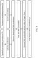
- FIG. 22 shows a modified merge list construction process.
- FIG. 23 shows an example of merge sharing node.
- FIG. 24 shows examples of disallowed ternary tree TT and binary tree BT partitioning.
- FIG. 25 shows an example of how new motion information can be constructed from neighboring motion information.
- FIG. 26 shows an example of how motion information can be constructed from neighboring motion information.
- FIG. 27 shows a flowchart of yet another example method for video processing.
- FIG. 28 is a block diagram of an example of a hardware platform for implementing a visual media decoding or a visual media encoding technique described in the present document.
- FIG. 29 shows a flowchart of yet another example method for video processing.
- FIG. 30 shows a flowchart of yet another example method for video processing.
- the present document relates to digital video coding and decoding. Section headings are used in the present document only to facilitate understanding, and do not limit scope of the disclosed embodiments in any way. Furthermore, while terminology from current working draft of the H.266 standard is used for reference, the disclosed techniques are equally applicable to other video codec technologies.
- Video codecs typically include an electronic circuit or software that compresses or decompresses digital video, and are continually being improved to provide higher coding efficiency.
- a video codec converts uncompressed video to a compressed format or vice versa.
- the compressed format usually conforms to a standard video compression specification, e.g., the High Efficiency Video Coding (HEVC) standard (also known as H.265 or MPEG-H Part 2), the Versatile Video Coding standard to be finalized, or other current and/or future video coding standards.
- HEVC High Efficiency Video Coding
- MPEG-H Part 2 the Versatile Video Coding standard to be finalized, or other current and/or future video coding standards.
- Video coding standards have evolved primarily through the development of the well-known ITU-T and ISO/IEC standards.
- the ITU-T produced H.261 and H.263, ISO/IEC produced MPEG-1 and MPEG-4 Visual, and the two organizations jointly produced the H.262/MPEG-2 Video and H.264/MPEG-4 Advanced Video Coding (AVC) and H.265/HEVC standards.
- AVC H.264/MPEG-4 Advanced Video Coding
- H.265/HEVC H.265/HEVC
- the video coding standards are based on the hybrid video coding structure wherein temporal prediction plus transform coding are utilized.
- Joint Video Exploration Team JVET was founded by VCEG and MPEG jointly in 2015. Since then, many new methods have been adopted by JVET and put into the reference software named Joint Exploration Model (JEM).
- JEM Joint Exploration Model
- the Joint Video Expert Team (JVET) between VCEG (06/16) and ISO/IEC JTC1 SC29/WG11 (MPEG)
- Embodiments of the disclosed technology may be applied to existing video coding standards (e.g., HEVC, H.265) and future standards to improve compression performance. Section headings are used in the present document to improve readability of the description and do not in any way limit the discussion or the embodiments (and/or implementations) to the respective sections only.
- Each inter-predicted PU has motion parameters for one or two reference picture lists.
- Motion parameters include a motion vector and a reference picture index. Usage of one of the two reference picture lists may also be signalled using inter_pred_idc. Motion vectors may be explicitly coded as deltas relative to predictors.
- a merge mode is specified whereby the motion parameters for the current PU are obtained from neighbouring PUs, including spatial and temporal candidates.
- the merge mode can be applied to any inter-predicted PU, not only for skip mode.
- the alternative to merge mode is the explicit transmission of motion parameters, where motion vector (to be more precise, motion vector differences (MVD) compared to a motion vector predictor), corresponding reference picture index for each reference picture list and reference picture list usage are signalled explicitly per each PU.
- Such a mode is named Advanced motion vector prediction (AMVP) in this disclosure.
- the PU When signalling indicates that one of the two reference picture lists is to be used, the PU is produced from one block of samples. This is referred to as ‘uni-prediction’. Uni-prediction is available both for P-slices and B-slices.
- Bi-prediction When signalling indicates that both of the reference picture lists are to be used, the PU is produced from two blocks of samples. This is referred to as ‘bi-prediction’. Bi-prediction is available for B-slices only.
- inter prediction is used to denote prediction derived from data elements (e.g., sample values or motion vectors) of reference pictures other than the current decoded picture.
- data elements e.g., sample values or motion vectors
- a picture can be predicted from multiple reference pictures.
- the reference pictures that are used for inter prediction are organized in one or more reference picture lists.
- the reference index identifies which of the reference pictures in the list should be used for creating the prediction signal.
- a single reference picture list, List 0 is used for a P slice and two reference picture lists, List 0 and List 1 are used for B slices. It should be noted reference pictures included in List 0/1 could be from past and future pictures in terms of capturing/display order.
- Step 1 Initial candidates derivation
- Step 2 Additional candidates insertion
- steps are also schematically depicted in FIG. 1 .
- For spatial merge candidate derivation a maximum of four merge candidates are selected among candidates that are located in five different positions.
- temporal merge candidate derivation a maximum of one merge candidate is selected among two candidates. Since constant number of candidates for each PU is assumed at decoder, additional candidates are generated when the number of candidates obtained from step 1 does not reach the maximum number of merge candidate (MaxNumMergeCand) which is signalled in slice header. Since the number of candidates is constant, index of best merge candidate is encoded using truncated unary binarization (TU). If the size of CU is equal to 8, all the PUs of the current CU share a single merge candidate list, which is identical to the merge candidate list of the 2N ⁇ 2N prediction unit.
- TU truncated unary binarization
- a maximum of four merge candidates are selected among candidates located in the positions depicted in FIG. 2 .
- the order of derivation is A 1 , B 1 , B 0 , A 0 and B 2 .
- Position B 2 is considered only when any PU of position A 1 , B 1 , B 0 , A 0 is not available (e.g. because it belongs to another slice or tile) or is intra coded.
- candidate at position A 1 is added, the addition of the remaining candidates is subject to a redundancy check which ensures that candidates with same motion information are excluded from the list so that coding efficiency is improved.
- not all possible candidate pairs are considered in the mentioned redundancy check. Instead only the pairs linked with an arrow in FIG. 3 are considered and a candidate is only added to the list if the corresponding candidate used for redundancy check has not the same motion information.
- FIG. 4 depicts the second PU for the case of N ⁇ 2N and 2N ⁇ N, respectively.
- candidate at position A 1 is not considered for list construction. In fact, by adding this candidate will lead to two prediction units having the same motion information, which is redundant to just have one PU in a coding unit.
- position B 1 is not considered when the current PU is partitioned as 2N ⁇ N.
- FIG. 4 shows example positions for the second PU of N ⁇ 2N and 2N ⁇ N partitions.
- a scaled motion vector is derived based on co-located PU belonging to the picture which has the smallest POC difference with current picture within the given reference picture list.
- the reference picture list to be used for derivation of the co-located PU is explicitly signalled in the slice header.
- the scaled motion vector for temporal merge candidate is obtained as illustrated by the dotted line in FIG.
- tb is defined to be the POC difference between the reference picture of the current picture and the current picture
- td is defined to be the POC difference between the reference picture of the co-located picture and the co-located picture.
- the reference picture index of temporal merge candidate is set equal to zero.
- the position for the temporal candidate is selected between candidates C0 and C1, as depicted in FIG. 6 . If PU at position C0 is not available, is intra coded, or is outside of the current coding tree unit (CTU aka. LCU, largest coding unit) row, position C1 is used. Otherwise, position C0 is used in the derivation of the temporal merge candidate.
- CTU current coding tree unit
- FIG. 6 shows example candidate positions for temporal merge candidate, C0 and C1.
- Zero merge candidate Combined bi-predictive merge candidates are generated by utilizing spatial and temporal merge candidates. Combined bi-predictive merge candidate is used for B-Slice only. The combined bi-predictive candidates are generated by combining the first reference picture list motion parameters of an initial candidate with the second reference picture list motion parameters of another. If these two tuples provide different motion hypotheses, they will form a new bi-predictive candidate. As an example, FIG.
- Zero motion candidates are inserted to fill the remaining entries in the merge candidates list and therefore hit the MaxNumMergeCand capacity. These candidates have zero spatial displacement and a reference picture index which starts from zero and increases every time a new zero motion candidate is added to the list.
- variable i 0 . . . numRef-1
- AMVP exploits spatio-temporal correlation of motion vector with neighbouring PUs, which is used for explicit transmission of motion parameters.
- a motion vector candidate list is constructed by firstly checking availability of left, above temporally neighbouring PU positions, removing redundant candidates and adding zero vector to make the candidate list to be constant length. Then, the encoder can select the best predictor from the candidate list and transmit the corresponding index indicating the chosen candidate. Similarly, with merge index signalling, the index of the best motion vector candidate is encoded using truncated unary. The maximum value to be encoded in this case is 2 ( FIG. 8 ). In the following sections, details about derivation process of motion vector prediction candidate are provided.
- FIG. 8 summarizes derivation process for motion vector prediction candidate.
- motion vector candidate two types are considered: spatial motion vector candidate and temporal motion vector candidate.
- spatial motion vector candidate derivation two motion vector candidates are eventually derived based on motion vectors of each PU located in five different positions as depicted in FIG. 2 .
- one motion vector candidate is selected from two candidates, which are derived based on two different co-located positions. After the first list of spatio-temporal candidates is made, duplicated motion vector candidates in the list are removed. If the number of potential candidates is larger than two, motion vector candidates whose reference picture index within the associated reference picture list is larger than 1 are removed from the list. If the number of spatio-temporal motion vector candidates is smaller than two, additional zero motion vector candidates is added to the list.
- a maximum of two candidates are considered among five potential candidates, which are derived from PUs located in positions as depicted in FIG. 2 , those positions being the same as those of motion merge.
- the order of derivation for the left side of the current PU is defined as A 0 , A 1 , and scaled A 0 , scaled A 1 .
- the order of derivation for the above side of the current PU is defined as B 0 , B 1 , B 2 , scaled B 0 , scaled B 1 , scaled B 2 .
- the no-spatial-scaling cases are checked first followed by the spatial scaling. Spatial scaling is considered when the POC is different between the reference picture of the neighbouring PU and that of the current PU regardless of reference picture list. If all PUs of left candidates are not available or are intra coded, scaling for the above motion vector is allowed to help parallel derivation of left and above MV candidates. Otherwise, spatial scaling is not allowed for the above motion vector.
- FIG. 9 is an illustration of motion vector scaling for spatial motion vector candidate.
- the motion vector of the neighbouring PU is scaled in a similar manner as for temporal scaling, as depicted as FIG. 9 .
- the main difference is that the reference picture list and index of current PU is given as input; the actual scaling process is the same as that of temporal scaling.
- AMVR Adaptive motion vector difference resolution
- TPM Triangular prediction mode
- ATMVP Alternative TMVP
- GBI Generalized Bi-Prediction
- BIO Bi-directional Optical flow
- IBC Intra Block Copy
- motion vector differences (between the motion vector and predicted motion vector of a PU) are signalled in units of quarter luma samples when use_integer_mv_flag is equal to 0 in the slice header.
- LAMVR locally adaptive motion vector resolution
- MVD can be coded in units of quarter luma samples, integer luma samples or four luma samples (i.e., 1 ⁇ 4-pel, 1-pel, 4-pel).
- the MVD resolution is controlled at the coding unit (CU) level, and MVD resolution flags are conditionally signalled for each CU that has at least one non-zero MVD components.
- a first flag is signalled to indicate whether quarter luma sample MV precision is used in the CU.
- the first flag (equal to 1) indicates that quarter luma sample MV precision is not used, another flag is signalled to indicate whether integer luma sample MV precision or four luma sample MV precision is used.
- the quarter luma sample MV resolution is used for the CU.
- the MVPs in the AMVP candidate list for the CU are rounded to the corresponding precision.
- AMVR mode is extended to affine coded blocks (aka Affine AMVR mode).
- TPM triangular prediction mode
- a CU into two triangular prediction units, in either diagonal or inverse diagonal direction.
- Each triangular prediction unit in the CU is inter-predicted using its own uni-prediction motion vector and reference frame index which are derived from a single uni-prediction candidate list.
- An adaptive weighting process is performed to the diagonal edge after predicting the triangular prediction units.
- the transform and quantization process are applied to the whole CU. It is noted that this mode is only applied to merge mode (note: skip mode is treated as a special merge mode).
- FIG. 10 A shows an example of 135 degree partition type (splitting from top-left corner to bottom-right corner).
- FIG. 10 B shows an example of 45 degree splitting patterns.
- FIGS. 10 A- 10 B show an illustration of splitting a CU into two triangular prediction units (two splitting patterns).
- the uni-prediction candidate list consists of five uni-prediction motion vector candidates. It is derived from seven neighboring blocks including five spatial neighboring blocks (1 to 5) and two temporal co-located blocks (6 to 7), as shown in FIG. 11 .
- the motion vectors of the seven neighboring blocks are collected and put into the uni-prediction candidate list according in the order of uni-prediction motion vectors, L0 motion vector of bi-prediction motion vectors, L1 motion vector of bi-prediction motion vectors, and averaged motion vector of the L0 and L1 motion vectors of bi-prediction motion vectors. If the number of candidates is less than five, zero motion vector is added to the list.
- Motion candidates added in this list for TPM are called TPM candidates, motion information derived from spatial/temporal blocks are called regular motion candidates.
- the motion information of List 0 is firstly scaled to List 1 reference picture, and the average of the two MVs (one is from original List 1, and the other is the scaled MV from List 0) is added to the TPM merge list, such a TPM candidate is called averaged uni-prediction from List 1 motion candidate and numCurrMergeCand increased by 1.
- FIG. 11 shows example position of the neighboring blocks.
- full pruning When inserting a candidate to the list, if it has to be compared to all previously added candidates to see whether it is identical to one of them, such a process is called full pruning.
- weighting factor groups are defined as follows:
- Weighting factor group ⁇ 7/8, 6/8, 5/8, 4/8, 3/8, 2/8, 1/8 ⁇ and ⁇ 6/8, 4/8, 2/8 ⁇ are used for the luminance and the chrominance samples, respectively.
- the blending region is dependent on the aspect ratio of the block.
- width of the weighed pixels are 7 for luma and 3 for chroma as defined above.
- the width is lengthened by a factor of (W/H) when width is greater than height. Each factor is repeated by (W/H) times before going to the next factor. In case height is greater than width, the width is the same as in square blocks, while they are repeated by (H/W) rows before shifting to the right by one pixel position.
- TPM Triangular Prediction Mode
- One bit flag to indicate whether TPM is used may be firstly signaled. Afterwards, the indications of two splitting patterns (as depicted in FIG. 10 ), and selected merge indices for each of the two partitions are further signaled.
- triangular prediction mode is also disabled.
- one bit flag may be signaled to indicate whether the triangular prediction mode is enabled or disabled for the block.
- Ctx index ((left block L available && L is coded with TPM ?)1:0)+((Above block A available && A is coded with TPM ?)1:0);
- FIG. 12 shows examples of neighboring blocks (A and L) used for context selection in TPM flag coding.
- HEVC high definition motion model
- MCP motion compensation prediction
- a simplified affine transform motion compensation prediction is applied with 4-parameter affine model and 6-parameter affine model.
- FIG. 13 A- 13 B the affine motion field of the block is described by two control point motion vectors (CPMVs) for the 4-parameter affine model and 3 CPMVs for the 6-parameter affine model.
- CPMVs control point motion vectors
- FIG. 13 A shows an example of a 4-parameter affine model.
- FIG. 13 B shows an example of a 6-parameter affine model.
- the motion vector field (MVF) of a block is described by the following equations with the 4-parameter affine model (wherein the 4-parameter are defined as the variables a, b, e and f) in equation (1) and 6-parameter affine model (wherein the 4-parameter are defined as the variables a, b, c, d, e and f) in equation (2) respectively:
- control point motion vectors (CPMV)
- (x, y) represents the coordinate of a representative point relative to the top-left sample within current block
- (mv h (x,y), mv v (x,y)) is the motion vector derived for a sample located at (x, y).
- the CP motion vectors may be signaled (like in the affine AMVP mode) or derived on-the-fly (like in the affine merge mode).
- w and h are the width and height of the current block.
- the division is implemented by right-shift with a rounding operation.
- the representative point is defined to be the center position of a sub-block, e.g., when the coordinate of the left-top corner of a sub-block relative to the top-left sample within current block is (xs, ys), the coordinate of the representative point is defined to be (xs+2, ys+2).
- the representative point is utilized to derive the motion vector for the whole sub-block.
- sub-block based affine transform prediction is applied.
- the motion vector of the center sample of each sub-block is calculated according to Equation (1) and (2), and rounded to 1/16 fraction accuracy.
- the motion compensation interpolation filters for 1/16-pel are applied to generate the prediction of each sub-block with derived motion vector.
- the interpolation filters for 1/16-pel are introduced by the affine mode.
- FIG. 14 shows an example of Affine MVF per sub-block.
- the high accuracy motion vector of each sub-block is rounded and saved as the same accuracy as the normal motion vector.
- AFFINE_INTER Similar to the translational motion model, there are also two modes for signaling the side information due affine prediction. They are AFFINE_INTER and AFFINE_MERGE modes.
- AF_INTER mode can be applied.
- An affine flag in CU level is signalled in the bitstream to indicate whether AF_INTER mode is used.
- an affine AMVP candidate list is constructed with three types of affine motion predictors in the following order, wherein each candidate includes the estimated CPMVs of the current block.
- the differences of the best CPMVs found at the encoder side (such as mv 0 mv 1 mv 2 in FIG. 17 ) and the estimated CPMVs are signalled.
- the index of affine AMVP candidate from which the estimated CPMVs are derived is further signalled.
- the checking order is similar to that of spatial MVPs in HEVC AMVP list construction.
- a left inherited affine motion predictor is derived from the first block in ⁇ A1, A0 ⁇ that is affine coded and has the same reference picture as in current block.
- an above inherited affine motion predictor is derived from the first block in ⁇ B1, B0, B2 ⁇ that is affine coded and has the same reference picture as in current block.
- the five blocks A1, A0, B1, B0, B2 are depicted in FIG. 16 .
- the CPMVs of the coding unit covering the neighboring block are used to derive predictors of CPMVs of current block. For example, if A1 is coded with non-affine mode and A0 is coded with 4-parameter affine mode, the left inherited affine MV predictor will be derived from A0. In this case, the CPMVs of a CU covering A0, as denoted by MV 0 N for the top-left CPMV and MV 1 N for the top-right CPMV in FIG.
- MV 0 C MV 1 C
- MV 2 C top-left (with coordinate (x0, y0)), top-right (with coordinate (x1, y1)) and bottom-right positions (with coordinate (x2, y2)) of current block.
- a constructed affine motion predictor consists of control-point motion vectors (CPMVs) that are derived from neighboring inter coded blocks, as shown in FIG. 17 , that have the same reference picture. If the current affine motion model is 4-parameter affine, the number of CPMVs is 2, otherwise if the current affine motion model is 6-parameter affine, the number of CPMVs is 3.
- the top-left CPMV mv 0 is derived by the MV at the first block in the group ⁇ A, B, C ⁇ that is inter coded and has the same reference picture as in current block.
- the top-right CPMV mv 1 is derived by the MV at the first block in the group ⁇ D, E ⁇ that is inter coded and has the same reference picture as in current block.
- the bottom-left CPMV mv 2 is derived by the MV at the first block in the group ⁇ F, G ⁇ that is inter coded and has the same reference picture as in current block.
- FIG. 15 A shows a 4-parameter affine model.
- FIG. 15 B shows a 6-parameter affine model.
- FIG. 16 shows an MVP for AF_INTER for inherited affine candidates.
- FIG. 17 shows an MVP for AF_INTER for constructed affine candidates
- mvd 1 and mvd 2 are predicted from mvd 0 .
- mv 0 mv 0 +mvd 0
- mv 1 mv 1 +mvd 1 +mvd 0
- mv 2 mv 2 +mvd 2 +mvd 0
- two motion vectors e.g., mvA(xA, yA) and mvB(xB, yB)
- newMV mvA+mvB and the two components of newMV is set to (xA+xB) and (yA+yB), respectively.
- a CU When a CU is applied in AF_MERGE mode, it gets the first block coded with affine mode from the valid neighbour reconstructed blocks. And the selection order for the candidate block is from left, above, above right, left bottom to above left as shown in FIG. 18 A (denoted by A, B, C, D, E in order). For example, if the neighbour left bottom block is coded in affine mode as denoted by A0 in FIG. 18 B , the Control Point (CP) motion vectors mv 0 N , mv 1 N and mv 2 N of the top left corner, above right corner and left bottom corner of the neighbouring CU/PU which contains the block A are fetched.
- CP Control Point
- the motion vector mv 0 C , mv 1 C and mv 2 C (which is only used for the 6-parameter affine model) of the top left corner/top right/bottom left on the current CU/PU is calculated based on mv 0 N , mv 1 N and mv 2 N .
- sub-block e.g. 4 ⁇ 4 block in VTM located at the top-left corner stores mv0
- the sub-block located at the top-right corner stores mv1 if the current block is affine coded.
- the sub-block located at the bottom-left corner stores mv2; otherwise (with the 4-parameter affine model), LB stores mv2′.
- Other sub-blocks stores the MVs used for MC.
- the MVF of the current CU is generated.
- an affine flag is signalled in the bitstream when there is at least one neighbour block is coded in affine mode.
- FIG. 18 A- 18 B show example candidates for AF_MERGE ( 18 A—five neighboring blocks, 18 B—CPMV predictor derivation).
- An affine merge candidate list is constructed with following steps:
- Inherited affine candidate means that the candidate is derived from the affine motion model of its valid neighbor affine coded block.
- the maximum two inherited affine candidates are derived from affine motion model of the neighboring blocks and inserted into the candidate list.
- the scan order is ⁇ A0, A1 ⁇ ; for the above predictor, the scan order is ⁇ B0, B1, B2 ⁇ .
- Constructed affine candidate means the candidate is constructed by combining the neighbor motion information of each control point.
- FIG. 19 shows an example of candidates position for affine merge mode.
- Intra block copy (a.k.a. IBC, or intra picture block compensation), also named current picture referencing (CPR) was adopted in HEVC screen content coding extensions (SCC).
- CPR current picture referencing
- SCC screen content coding extensions
- This tool is very efficient for coding of screen content video in that repeated patterns in text and graphics rich content occur frequently within the same picture. Having a previously reconstructed block with equal or similar pattern as a predictor can effectively reduce the prediction error and therefore improve coding efficiency.
- An example of the intra block compensation is illustrated in FIG. 20 .
- FIG. 20 shows an example of intra-picture block copy.
- the use of the IBC mode is signaled at both sequence and picture level.
- SPS sequence parameter set
- the IBC mode can be enabled at picture level.
- the IBC mode is enabled at picture level, the current reconstructed picture is treated as a reference picture. Therefore, no syntax change on block level is needed on top of the existing VVC inter mode to signal the use of the IBC mode.
- sub-block merge candidate list The sub-block related motion candidates are put in a separate merge list is named as ‘sub-block merge candidate list’.
- the sub-block merge candidate list includes affine merge candidates, and ATMVP candidate, and/or sub-block based STMVP candidate.
- the sub-block merge candidate list is filled with candidates in the following order:
- ATMVP merge candidate is generated, the following process is applied:
- HMVP history-based motion vector prediction
- HMVP the previously coded motion information is stored.
- the motion information of a previously coded block is defined as an HMVP candidate.
- Multiple HMVP candidates are stored in a table, named as the HMVP table, and this table is maintained during the encoding/decoding process on-the-fly.
- the HMVP table is emptied when starting coding/decoding a new tile/LCU row/a slice. Whenever there is an inter-coded block and non-sub-block, non-TPM mode, the associated motion information is added to the last entry of the table as a new HMVP candidate.
- the overall coding flow is depicted in FIG. 21 .
- HMVP candidates could be used in both AMVP and merge candidate list construction processes.
- FIG. 22 depicts a modified merge candidate list construction process (highlighted in blue).
- HMVP candidates stored in the HMVP table could be utilized to fill in the merge candidate list.
- the HMVP candidates in the table are inserted in a descending order of indices. The last entry in the table is firstly added to the list, while the first entry is added in the end. Similarly, redundancy removal is applied on the HMVP candidates. Once the total number of available merge candidates reaches the maximal number of merge candidates allowed to be signaled, the merge candidate list construction process is terminated.
- HMVP table contains up to 5 regular motion candidates and each of them is unique.
- HMVP candidates are also applicable for the IBC merge list.
- another 5 IBC candidates may be stored.
- the regular and IBC candidates are stored in the same HMVP table. However, they are utilized and updated independently.
- Two counters are maintained to indicate how many regular motion candidates and how many IBC motion candidates in the HMVP table. Therefore, it is equal to use 2 HMVP tables, one is for the regular merge modes, and the other for the IBC mode.
- TMVP zero vector means unavailable as it is invalid. It is noted that for a spatial neighboring block, only if it is coded with IBC mode, the associated motion information may be added to the IBC merge list. Meanwhile, for the HMVP part, only the last few HMVP candidates (which are stored IBC motion candidates) may be considered in the IBC merge list.
- the ancestor node is named merge sharing node.
- the shared merging candidate list is generated at the merge sharing node pretending the merge sharing node is a leaf CU.
- a temporary HMVP table is allocated. Before, the original HMVP table must be copied to the temporary HMVP table when entering the first CU of one shared region.
- one 8 ⁇ 8 is QT partitioned into 4 4 ⁇ 4 CUs.
- the history list Before doing the first CU (e.g., the left-top 4 ⁇ 4 CU), the history list must be copied into the temporary HMVP table (HmvpCandListShared[ ]), and, when each 4 ⁇ 4 inside the shared parent (merge sharing node in the figure) need the history list for merge mode, it will use motion candidates in the temporary HMVP table.
- the original HMVP table is updated accordingly.
- FIG. 23 shows an example of merge sharing node.
- VPDUs Virtual Pipeline Data Units
- Virtual pipeline data units are defined as non-overlapping units in a picture.
- successive VPDUs are processed by multiple pipeline stages at the same time.
- the VPDU size is roughly proportional to the buffer size in most pipeline stages, so it is important to keep the VPDU size small.
- the VPDU size can be set to maximum transform block (TB) size.
- TB maximum transform block
- TT ternary tree
- BT binary tree
- FIG. 24 shows examples of disallowed TT and BT partitioning.
- FIG. 25 shows an example of how new motion information can be constructed from neighboring motion information.
- FIG. 26 shows an example of how motion information can be constructed from neighboring motion information.
- MVy LeftMVy + DiffMVy * ( Ydistance CTUSIZE - TopYOffset + LeftYOffset )
- FIG. 27 is a flowchart showing an example method 2700 of video processing.
- the method includes initializing ( 2702 ), during a conversion between a video region and a bitstream representation of the video region, a motion vector predictor (MVP) table from multiple stored MVP tables, wherein each of the multiple MVPs includes motion information previously considered during the conversion; and performing ( 2704 ) the conversion using the MVP table selected from multiple stored MVP tables.
- MVP motion vector predictor
- FIG. 28 is a block diagram of a video processing apparatus 2800 .
- the apparatus 2800 may be used to implement one or more of the methods described herein.
- the apparatus 2800 may be embodied in a smartphone, tablet, computer, Internet of Things (IoT) receiver, and so on.
- the apparatus 2800 may include one or more processors 2802 , one or more memories 2804 and video processing hardware 2806 .
- the processor(s) 2802 may be configured to implement one or more methods described in the present document.
- the memory (memories) 2804 may be used for storing data and code used for implementing the methods and techniques described herein.
- the video processing hardware 2806 may be used to implement, in hardware circuitry, some techniques described in the present document.
- a method for video processing comprising: initializing, during a conversion between a video region and a bitstream representation of the video region, a motion vector predictor (MVP) table from multiple stored MVP tables, wherein each of the multiple MVPs includes motion information previously considered during the conversion; and performing the conversion using the MVP table selected from multiple stored MVP tables.
- MVP motion vector predictor
- the initializing the MVP table includes initializing the MVP table using one or more MVP tables of neighboring video regions.
- the pruning criterion specifies to skip pruning of merge and alternate MVP candidates for the video region that meets skipping criterion at a left or top boundary of a coding tree unit of the video.
- a method for video processing comprising: constructing, during a conversion between a video region and a bitstream representation of the video region, one or more entries of a motion vector predictor (MVP) table from one or more stored MVP tables, wherein each MVP table includes motion information previously considered during the conversion, a flag indicating motion information is inherited from previous MVP table or added in a current region as a new motion information; and performing the conversion using the MVP table selected from multiple stored MVP tables.
- MVP motion vector predictor
- An apparatus comprising a processor configured to implement the method in any one of clauses 1 to 31.
- a computer readable media having stored thereon a processor-implementable program code for implementing a method recited in any of clauses 1 to 31.
- FIG. 29 is a flowchart for an example method 2900 of video processing.
- the method 2900 includes initializing ( 2902 ), for a conversion between a first region of video and a bitstream representation of the first region, a first history motion vector predictor (HMVP) table associated with the first region based on at least one of stored multiple HMVP tables, the multiple HMVP tables being used to store motion information associated with regions coded prior the first region; and performing ( 2904 ) the conversion by using the initialized first HMVP table which includes at least one motion candidate.
- HMVP history motion vector predictor
- the multiple HMVP tables include one or multiple HMVP tables associated with neighboring regions of the first region.
- the first HMVP table is initialized based on the multiple HMVP tables associated with neighboring regions of the first region.
- the first HMVP table is initialized based on one HMVP table associated with a neighboring region of the first region.
- the multiple HMVP tables associated with neighboring regions of the first region include at least one of HMVP table associated with a left region, HMVP table associated with a top region, HMVP table associated with a top left region, and HMVP table associated with a top right region of the first region.
- the multiple HMVP tables associated with neighboring regions of the first region include HMVP table associated with a top region and/or HMVP table associated with a top right region of the first region.
- the method further includes: associating the first HMVP table with the first region; and storing the first HMVP table for subsequent use after the conversion of the first region.
- the region is a coding tree unit (CTU) or a Virtual pipeline data unit (VPDU).
- CTU coding tree unit
- VPDU Virtual pipeline data unit
- FIG. 30 is a flowchart for an example method 3000 of video processing.
- the method 3000 includes generating ( 3002 ), for a conversion between a first region of video and a bitstream representation of the first region, a new history motion vector predictor (HMVP) table associated with the first region based on multiple HMVP tables associated with other regions, the multiple HMVP tables being used to store motion information associated with other regions coded prior the first region; and performing ( 3004 ) the conversion by using the generated new HMVP table which includes at least one motion candidate.
- HMVP new history motion vector predictor
- the region is a coding tree unit (CTU) or a Virtual pipeline data unit (VPDU).
- CTU coding tree unit
- VPDU Virtual pipeline data unit
- inherited motion information from the multiple HMVP tables are combined into the new HMVP table.
- the new HMVP table is generated by adding all motion information from a predetermined number of HMVP tables of the multiple HMVP tables in a pre-defined order.
- the pre-defined order is to add all motion information from a first HMVP table, followed by all motion information from a second HMVP table until all motion information from the predetermined number of HMVP tables are added sequentially.
- the predetermined number is 3.
- the pre-defined order is to add a first motion information from all of the predetermined number of HMVP tables, followed by a second motion information from all of the predetermined number of HMVP tables, until all motion information from the predetermined number of HMVP tables are interleaved and added.
- the predetermined number is 2 or 3.
- the first HMVP table is generated by combing the multiple HMVP tables associated with neighboring regions of the first region.
- the multiple HMVP tables associated with neighboring regions of the first region include HMVP table associated with a left region, HMVP table associated with a top region, HMVP table associated with a top left region, and HMVP table associated with a top right region of the first region.
- the multiple HMVP tables associated with neighboring regions of the first region include HMVP table associated with a top region and HMVP table associated with a top right region of the first region.
- the motion information in the multiple HMVP tables associated with other regions are pruned out based on a pruning criterion before the motion information in the multiple HMVP tables are added to the new HMVP table.
- the motion information from a left column buffer of the first CTU exists in a left HMVP table associated with a CTU on the left of first CTU
- the motion information is pruned out from the left HMVP table, wherein the left column buffer of the first CTU is the right most columns of a left CTU of the first CTU.
- HMVP merge and/or AMVP candidates is skipped.
- the motion information stored in any of the entries of the left HMVP table matches to any one of the motion information from the left column buffer of the first CTU, the motion information is removed from the left HMVP table.
- the motion information stored in any of the entries of the left HMVP table is within a certain amount of distance to any one of the motion information from the left column buffer of the first CTU, the motion information is removed from the left HMVP table.
- the distance metrics include at least one of L1-norm and L2-norm, wherein the L1-norm is calculated as the sum of the absolute values of a vector, the L2-norm is calculated as the square root of the sum of the squared vector values.
- whether the pruning occurs or not is determined based on a threshold, the threshold being associated with size of the first region or the distance.
- the threshold is signaled in at least one of sequence parameter set (SPS), picture parameter set (PPS) and tile group header.
- SPS sequence parameter set
- PPS picture parameter set
- tile group header the threshold is signaled in at least one of sequence parameter set (SPS), picture parameter set (PPS) and tile group header.
- the motion information is pruned out from the top HMVP table wherein the above line buffer of the first CTU is the bottom most rows of an above CTU of the first CTU.
- HMVP merge and/or AMVP candidates is skipped.
- a constructed motion information which is constructed from two motion information from two different HMVP tables of the multiple HMVP tables is added to the new HMVP table.
- each motion information in the HMVP table includes location information including horizontal offset and vertical offset from top left corner of current CTU and a flag indicating that it is motion information of the current CTU or not.
- a CTU-level syntax element is provided to indicate motion information from either the top or the left CTU is to be used.
- the constructed motion information is constructed from motion information from a top HMVP table associated with a top region of the first region and motion information from a left HMVP table associated with a left region of the first region.
- the constructed motion information is constructed based on a difference (DiffMV) between the motion information (TopMV) from the top HMVP table and the motion information (LefMV) from the left HMVP table.
- DiffMV difference between the motion information (TopMV) from the top HMVP table and the motion information (LefMV) from the left HMVP table.
- the constructed motion information MV is calculated as following:
- MVx LeftMVx + DiffMVx * ( CTUSIZE - LeftXOffset CTUSIZE - LeftXOffset + TopXOffset )
- MVy LeftMVy + DiffMVy * ( LeftYOffset CTUSIZE - TopYOffset + LeftYOffset )
- MVx is a horizontal component of the MV
- TopXOffset is a horizontal offset of the motion information TopMV
- LeftXOffset is a horizontal offset of the motion information LefMV
- MVy is a horizontal component of the MV
- TopYOffset is a vertical offset of the motion information TopMV
- LeftYOffset is a vertical offset of the motion information LefMV
- CTUSIZE is width and/or height of the current CTU.
- a constructed motion information which is constructed from two motion information from one or more HMVP tables of the multiple HMVP tables is used as a candidate of merge list in Coding Unit (CU) of the first region.
- the two motion information are chosen from any combination of neighboring HMVP tables including current HMVP table.
- one motion information is from left HMVP table and the other motion information is from top HMVP table.
- one motion information is from left HMVP table and the other motion information is from the current HMVP table.
- one motion information is from top HMVP table and the other motion information is from the current HMVP table.
- the two motion information are both from the current HMVP table.
- the constructed motion information in the CU is used as a candidate of various merge list, which is not currently used.
- the various merge list includes a triangle merge list.
- the constructed motion information is constructed based on a difference (DiffMV) between the motion information (TopMV) from the top HMVP table and the motion information (LefMV) from the left HMVP table and distances between the two motion information and the current CU.
- DiffMV difference between the motion information (TopMV) from the top HMVP table and the motion information (LefMV) from the left HMVP table and distances between the two motion information and the current CU.
- the constructed motion information MV is calculated as following:
- MVx LeftMVx + DiffMVx * ( Xdistance CTUSIZE - LeftXOffset + TopXOffset )
- MVy LeftMVy + DiffMVy * ( Ydistance CTUSIZE - TopYOffset + LeftYOffset )
- MVx is a horizontal component of the MV
- TopXOffset is a horizontal offset of the motion information TopMV
- LeftXOffset is a horizontal offset of the motion information LefMV
- MVy is a horizontal component of the MV
- TopYOffset is a vertical offset of the motion information TopMV
- LeftYOffset is a vertical offset of the motion information LefMV
- CTUSIZE is width and/or height of the current CTU.
- the region including a Virtual pipeline data unit (VPDU) or a parallel processing size defined in at least one of SPS, PPS and Tile Group header.
- VPDU Virtual pipeline data unit
- the HMVP table is reset at the beginning of each sub-CTU row within the tile group.
- inherited HMVP tables from one or more of top-left sub-CTU, top sub-CTU, and top-right sub-CTU are available for constructing the new HMVP table for the current sub-CTU.
- HMVP tables from top-left sub-CTU and top sub-CTU are available for constructing the new HMVP table for the current sub-CTU.
- any combinations of HMVP tables from left sub-CTU, top-left sub-CTU, top sub-CTU, and top-right sub-CTU are available for constructing the new HMVP table for the current sub-CTU.
- the generated HMVP table is used in parallel processing in a Virtual pipeline data unit (VPDU) or a parallel processing size defined in at least one of SPS, PPS and Tile Group header without updating.
- VPDU Virtual pipeline data unit
- the HMVP tables associated with regions use memory compression to save bandwidth reading from DDR memory.
- the memory compress includes mantissa and exponent.
- the conversion generates the first region of video from the bitstream representation.
- the conversion generates the bitstream representation from the first region of video.
- Implementations of the subject matter and the functional operations described in this patent document can be implemented in various systems, digital electronic circuitry, or in computer software, firmware, or hardware, including the structures disclosed in this specification and their structural equivalents, or in combinations of one or more of them. Implementations of the subject matter described in this specification can be implemented as one or more computer program products, i.e., one or more modules of computer program instructions encoded on a tangible and non-transitory computer readable medium for execution by, or to control the operation of, data processing apparatus.
- the computer readable medium can be a machine-readable storage device, a machine-readable storage substrate, a memory device, a composition of matter effecting a machine-readable propagated signal, or a combination of one or more of them.
- data processing unit or “data processing apparatus” encompasses all apparatus, devices, and machines for processing data, including by way of example a programmable processor, a computer, or multiple processors or computers.
- the apparatus can include, in addition to hardware, code that creates an execution environment for the computer program in question, e.g., code that constitutes processor firmware, a protocol stack, a database management system, an operating system, or a combination of one or more of them.
- a computer program (also known as a program, software, software application, script, or code) can be written in any form of programming language, including compiled or interpreted languages, and it can be deployed in any form, including as a stand-alone program or as a module, component, subroutine, or other unit suitable for use in a computing environment.
- a computer program does not necessarily correspond to a file in a file system.
- a program can be stored in a portion of a file that holds other programs or data (e.g., one or more scripts stored in a markup language document), in a single file dedicated to the program in question, or in multiple coordinated files (e.g., files that store one or more modules, sub programs, or portions of code).
- a computer program can be deployed to be executed on one computer or on multiple computers that are located at one site or distributed across multiple sites and interconnected by a communication network.
- the processes and logic flows described in this specification can be performed by one or more programmable processors executing one or more computer programs to perform functions by operating on input data and generating output.
- the processes and logic flows can also be performed by, and apparatus can also be implemented as, special purpose logic circuitry, e.g., an FPGA (field programmable gate array) or an ASIC (application specific integrated circuit).
- processors suitable for the execution of a computer program include, by way of example, both general and special purpose microprocessors, and any one or more processors of any kind of digital computer.
- a processor will receive instructions and data from a read only memory or a random access memory or both.
- the essential elements of a computer are a processor for performing instructions and one or more memory devices for storing instructions and data.
- a computer will also include, or be operatively coupled to receive data from or transfer data to, or both, one or more mass storage devices for storing data, e.g., magnetic, magneto optical disks, or optical disks.
- mass storage devices for storing data, e.g., magnetic, magneto optical disks, or optical disks.
- a computer need not have such devices.
- Computer readable media suitable for storing computer program instructions and data include all forms of nonvolatile memory, media and memory devices, including by way of example semiconductor memory devices, e.g., EPROM, EEPROM, and flash memory devices.
- semiconductor memory devices e.g., EPROM, EEPROM, and flash memory devices.
- the processor and the memory can be supplemented by, or incorporated in, special purpose logic circuitry.
Abstract
Description
-
- Step 1.1: Spatial candidates derivation
- Step 1.2: Redundancy check for spatial candidates
- Step 1.3: Temporal candidates derivation
-
- Step 2.1: Creation of bi-predictive candidates
- Step 2.2: Insertion of zero motion candidates
-
- (1) Same reference picture list, and same reference picture index (same POC)
- (2) Different reference picture list, but same reference picture (same POC)
-
- (3) Same reference picture list, but different reference picture (different POC)
- (4) Different reference picture list, and different reference picture (different POC)
-
- 1) Obtain regular motion candidates from A1, B1, B0, A0, B2, Col and Col2 (corresponding to block 1-7 in
FIG. 11 ) with full pruning operations when adding a regular motion candidate from spatial neighboring blocks. - 2) Set variable numCurrMergeCand=0
- 3) For each regular motion candidates derived from A1, B1, B0, A0, B2, Col and Col2, if not pruned and numCurrMergeCand is less than 5, if the regular motion candidate is uni-prediction (either from
List 0 or List 1), it is directly added to the merge list as an TPM candidate with numCurrMergeCand increased by 1. Such a TPM candidate is named ‘originally uni-predicted candidate’.- Full pruning is applied.
- 4) For each motion candidates derived from A1, B1, B0, A0, B2, Col and Col2, if not pruned, and numCurrMergeCand is less than 5, if the regular motion candidate is bi-prediction, the motion information from
List 0 is added to the TPM merge list (that is, modified to be uni-prediction from List 0) as a new TPM candidate and numCurrMergeCand increased by 1. Such a TPM candidate is named ‘Truncated List0-predicted candidate’. - Full pruning is applied.
- 5) For each motion candidates derived from A1, B1, B0, A0, B2, Col and Col2, if not pruned, and numCurrMergeCand is less than 5, if the regular motion candidate is bi-prediction, the motion information from
List 1 is added to the TPM merge list (that is, modified to be uni-prediction from List 1) and numCurrMergeCand increased by 1. Such a TPM candidate is named ‘Truncated List1-predicted candidate’. - Full pruning is applied.
- 6) For each motion candidates derived from A1, B1, B0, A0, B2, Col and Col2, if not pruned, and numCurrMergeCand is less than 5, if the regular motion candidate is bi-prediction,
- 1) Obtain regular motion candidates from A1, B1, B0, A0, B2, Col and Col2 (corresponding to block 1-7 in
-
- Full pruning is applied.
- 7) If numCurrMergeCand is less than 5, zero motion vector candidates are added.
Ctx index=((left block L available && L is coded with TPM?)1:0)+((Above block A available && A is coded with TPM?)1:0);
-
- If the current affine motion model is 4-parameter affine, then a constructed affine motion predictor is inserted into the candidate list only if both
mv 0 andmv 1 are founded, that is,mv 0 andmv 1 are used as the estimated CPMVs for top-left (with coordinate (x0, y0)), top-right (with coordinate (x1, y1)) positions of current block. - If the current affine motion model is 6-parameter affine, then a constructed affine motion predictor is inserted into the candidate list only if
mv 0,mv 1 andmv 2 are all founded, that is,mv 0,mv 1 andmv 2 are used as the estimated CPMVs for top-left (with coordinate (x0, y0)), top-right (with coordinate (x1, y1)) and bottom-right (with coordinate (x2, y2)) positions of current block.
- If the current affine motion model is 4-parameter affine, then a constructed affine motion predictor is inserted into the candidate list only if both
-
- 1) Derive an affine motion predictor by setting all CPMVs equal to
mv 2 if available. - 2) Derive an affine motion predictor by setting all CPMVs equal to
mv 1 if available. - 3) Derive an affine motion predictor by setting all CPMVs equal to
mv 0 if available. - 4) Derive an affine motion predictor by setting all CPMVs equal to HEVC TMVP if available.
- 5) Derive an affine motion predictor by setting all CPMVs to zero MV.
- 1) Derive an affine motion predictor by setting all CPMVs equal to
mv 0 =
mv 1 =
mv 2 =
-
- a) The motion information for the control points is derived firstly from the specified spatial neighbors and temporal neighbor shown in
FIG. 19 . CPk (k=1, 2, 3, 4) represents the k-th control point. A0, A1, A2, B0, B1, B2 and B3 are spatial positions for predicting CPk (k=1, 2, 3); T is temporal position for predicting CP4. The coordinates of CP1, CP2, CP3 and CP4 is (0, 0), (W, 0), (H, 0) and (W, H), respectively, where W and H are the width and height of current block.
- a) The motion information for the control points is derived firstly from the specified spatial neighbors and temporal neighbor shown in
-
- For CP1, the checking priority is B2→B3→A2. B2 is used if it is available. Otherwise, if B2 is available, B3 is used. If both B2 and B3 are unavailable, A2 is used. If all the three candidates are unavailable, the motion information of CP1 cannot be obtained.
- For CP2, the checking priority is B1→B0.
- For CP3, the checking priority is A1→A0.
- For CP4, T is used.
- b) Secondly, the combinations of controls points are used to construct an affine merge candidate.
- I. Motion information of three control points are needed to construct a 6-parameter affine candidate. The three control points can be selected from one of the following four combinations ({CP1, CP2, CP4}, {CP1, CP2, CP3}, {CP2, CP3, CP4}, {CP1, CP3, CP4}). Combinations {CP1, CP2, CP3}, {CP2, CP3, CP4}, {CP1, CP3, CP4} will be converted to a 6-parameter motion model represented by top-left, top-right and bottom-left control points.
- II. Motion information of two control points are needed to construct a 4-parameter affine candidate. The two control points can be selected from one of the two combinations ({CP1, CP2}, {CP1, CP3}). The two combinations will be converted to a 4-parameter motion model represented by top-left and top-right control points.
- III. The combinations of constructed affine candidates are inserted into to candidate list as following order:
- {CP1, CP2, CP3}, {CP1, CP2, CP4}, {CP1, CP3, CP4}, {CP2, CP3, CP4}, {CP1, CP2}, {CP1, CP3}
- i. For each combination, the reference indices of list X for each CP are checked, if they are all the same, then this combination has valid CPMVs for list X. If the combination does not have valid CPMVs for both
list 0 andlist 1, then this combination is marked as invalid. Otherwise, it is valid, and the CPMVs are put into the sub-block merge list.
3) Padding with Zero Motion Vectors
-
- It is treated as a special inter mode. Therefore, merge and skip modes are also available for the IBC mode. The merge candidate list construction is unified, containing merge candidates from the neighboring positions that are either coded in the IBC mode or the HEVC inter mode. Depending on the selected merge index, the current block under merge or skip mode can merge into either an IBC mode coded neighbor or otherwise an normal inter mode coded one with different pictures as reference pictures.
- The motion vector for the IBC mode, also referred as block vector, is coded with integer-pel precision, but stored in memory in 1/16-pel precision after decoding as quarter-pel precision is required in interpolation and deblocking stages. When used in motion vector prediction for the IBC mode, the stored vector predictor will be right shifted by 4.
- Search range: it is restricted to be within the current CTU.
- CPR is disallowed when affine mode/triangular mode/GBI/weighted prediction is enabled.
-
- 1) Sub-block merge candidate list: it includes ATMVP and affine merge candidates. One merge list construction process is shared for both affine modes and ATMVP mode. Here, the ATMVP and affine merge candidates may be added in order. Sub-block merge list size is signaled in slice header, and maximum value is 5.
- 2) Uni-Prediction TPM merge list: For triangular prediction mode, one merge list construction process for the two partitions is shared even two partitions could select their own merge candidate index. When constructing this merge list, the spatial neighbouring blocks and two temporal blocks of the block are checked. The motion information derived from spatial neighbours and temporal blocks are called regular motion candidates in our IDF. These regular motion candidates are further utilized to derive multiple TPM candidates. Please note the transform is performed in the whole block level, even two partitions may use different motion vectors for generating their own prediction blocks. Uni-Prediction TPM merge list size is fixed to be 5.
- 3) Regular merge list: For remaining coding blocks, one merge list construction process is shared. Here, the spatial/temporal/HMVP, pairwise combined bi-prediction merge candidates and zero motion candidates may be inserted in order. Regular merge list size is signaled in slice header, and maximum value is 6. MMVD,
- 4) IBC merge list: it is done in a similar way as the regular merge list.
-
- a. ATMVP candidate (maybe available or unavailable);
- b. Affine merge lists (including Inherited Affine candidates; and Constructed Affine candidates)
- c. Padding as zero MV 4-parameter affine model
-
- a. Check neighbouring blocks A1 as shown in
FIG. 2 in order, to find the first inter-coded, but not CPR-coded block, denoted as block X; - b. Initialize TMV=(0,0). If there is a MV (denoted as MV′) of block X, referring to the collocated reference picture (as signaled in the slice header), TMV is set equal to MV′.
- c. Suppose the center point of the current block is (x0, y0), then locate a corresponding position of (x0,y0) as M=(x0+MV′x, y0+MV′y) in the collocated picture. Find the block Z covering M.
- i. If Z is intra-coded, then ATMVP is unavailable;
- ii. If Z is inter-coded, MVZ_0 and MVZ_1 for the two lists of block Z are scaled to (
Reflist 0 index 0) and (Reflist 1 index 0) as MVdefault0, MVdefault1, and stored. - d. For each 8×8 sub-block, suppose its center point is (x0S, y0S), then locate a corresponding position of (x0S, y0S) as MS=(x0S+MV′x, y0S+MV′y) in the collocated picture. Find the block ZS covering MS.
- i. If ZS is intra-coded, MVdefault0, MVdefault1 are assigned to the sub-block;
- ii. If ZS is inter-coded, MVZS_0 and MVZS_1 for the two lists of block ZS are scaled to (
Reflist 0 index 0) and (Reflist 1 index 0) and are assigned to the sub-block;
- a. Check neighbouring blocks A1 as shown in
-
- If the block has luma samples no larger than 32, and split to 2 4×4 child blocks, sharing merge lists between very small blocks (e.g. two adjacent 4×4 blocks) is used.
- If the block has luma samples larger than 32, however, after a split, at least one child block is smaller than the threshold (32), all child blocks of that split share the same merge list (e.g. 16×4 or 4×16 split ternary or 8×8 with quad split).
-
- TT split is not allowed for a CU with either width or height, or both width and height equal to 128.
- For a 128×N CU with N≤64 (i.e. width equal to 128 and height smaller than 128), horizontal BT is not allowed.
- For a N×128 CU with N≤64 (i.e. height equal to 128 and width smaller than 128), vertical BT is not allowed.
-
- 1) The HMVP table for coding current CTU only contains motion information in previous CTUs in the same CTUs since it is reset at the beginning of a new CTU new. Therefore, it couldn't utilize the motion information from above CTUs.
- 2) HMVP table is always reset in beginning of each CTU row due to parallelism.
- 3) Some motion information in HMVP table may be the same as the spatial motion information already added into merge list.
- 4) HMVP table is currently being used in either regular merge list or IBC merge list. History-based motion information can be used more widely in different merge list.
-
- 1. Multiple HMVP tables may be stored in the encoding/decoding process and before encoding/decoding one block, an HMVP table may be initialized according to the selected HMVP tables.
- a. In one example, after encoding/decoding a first region (e.g., one CTU or VPDU), the associated HMVP table (e.g., before encoding/decoding a second region) may be stored associated with the first region.
- b. In one example, an HMVP table for encoding/decoding the current region may be initialized based on multiple HMVP tables of neighboring regions.
- c. In one example, an HMVP table for encoding/decoding the current region may be initialized based on one HMVP table of a neighboring region.
- d. In one example, the HMVP tables (not limited to left only) of neighboring regions may be that associated from left, top, top left, or top right region of current region.
- e. Alternatively, the HMVP tables (not limited to left only) of neighboring regions may be that associated from top or top right region of current region.
- 2. A new HMVP table for encoding/decoding one region may be generated according to multiple HMVP tables associated with other regions.
- a. Inherited motion information from multiple tables can be combined into a new HMVP table.
- b. In one example, one combining order is to add all motion information from the first table, and then add all motion information from second table, and add all from 3rd table, sequentially, etc. al.
- i. In one example, one combining order is to add all motion information from the first table, and then add all motion information from second table, and so on sequentially.
- ii. Alternatively, a combining order is to add one from first table and take next one from second table, take next one from 3rd table, etc. al, repeatedly (interleaved between the first, the second, and 3rd tables).
- iii. Alternatively, a combining order is to add one from first table and take next one from second table repeatedly only with limited tables (interleaved between the first and the second tables).
- c. In one example, one new HMVP table is to combine HMVP tables of left and top right regions.
- d. In one example, one new HMVP table is to combine HMVP tables of left, top, top left, and top right regions.
- 3. Motion information in HMVP tables of other regions may be pruned out first optionally before being added the motion information into the new HMVP table.
- a. When motion information next to the current CTU (i.e., left column buffer) exists in left HMVP table, it can be pruned out. The pruning of HMVP merge/AMVP candidates can be skipped when a CU locates at the left boundary of the CTU.
- i. In one example, when the motion information stored in any of the entries of the HMVP table matches to any one of the motion information from the left column, it is removed from the HMVP table.
- ii. In one example, when the motion information stored in any of the entries of the HMVP table are within a certain amount of distance to any one of the motion information from the left column, it is removed from the HMVP table. The distance metrics can include but not limited to the L1-norm and the L2-norm. In addition, the threshold for determining such pruning occurs or not can be determined based on the threshold (e.g., block size or distance). In another example, such threshold can be signaled in the SPS/PPS/Tile Group header.
- b. When motion information above to the current CTU (i.e., above line buffer) exists in top HMVP table, it can be pruned out. The pruning of HMVP merge/AMVP candidates can be skipped when a CU locates at the top boundary of the CTU.
- a. When motion information next to the current CTU (i.e., left column buffer) exists in left HMVP table, it can be pruned out. The pruning of HMVP merge/AMVP candidates can be skipped when a CU locates at the left boundary of the CTU.
- 4. Constructed motion information from two different tables may be added to a new HMVP table.
- a. Each motion information in HMVP table has location information such as x and y offset from top left corner of current CTU and a flag indicating that it is motion information of current CTU or not. Alternatively, there is a CTU-level syntax element indicating motion information from either the top or the left CTU should be used.
- b. Generate the new motion information with one motion information from left CTU and another motion information from top CTU which is available in HMVP table.
- i. New motion information considering top left corner can be derived based on its distance of two motion information of HMVP tables. One example is as follows. Assume that motion information of blue colored CU in left and top CTU is in HMVP table as below.
- 1. Multiple HMVP tables may be stored in the encoding/decoding process and before encoding/decoding one block, an HMVP table may be initialized according to the selected HMVP tables.
-
- 5. One variation for constructed motion information may be considered to a candidate of merge list in each CU considering its position.
- a. Two motion information may be chosen with any combination of different neighboring HMVP tables including current HMVP table. Below are some examples and it is not limited to only those combination.
- i. First example is one from left and another from top HMVP table.
- ii. Second example is one from left and another from current HMVP table.
- iii. Third example is one from top and another from current HMVP table.
- iv. Fourth example is both from current HMVP tables.
- b. Constructed motion information in CU may be used as a candidate of various merge list, which is not currently used. One example is triangle merge list.
- c. Below is one example to construct new motion information with two motion information from left and top HMVP table. The distance metrics may include but not limited to the L1-norm and the L2-norm. DiffMVx and DiffMVy is same in 5.b.
- a. Two motion information may be chosen with any combination of different neighboring HMVP tables including current HMVP table. Below are some examples and it is not limited to only those combination.
- 5. One variation for constructed motion information may be considered to a candidate of merge list in each CU considering its position.
-
- 6. When a sub-CTU level parallel processing is available, e.g. VPDU or parallel processing size (i.e., predefined area or any size defined in SPS/PPS/Tile Group header), the aforementioned techniques may be applied to each sub-CTU row or parallel processing size.
- a. In one example, the HMVP table is reset at the beginning of each sub-CTU row within the tile group.
- b. In one example, the inherited HMVP tables from top-left, top, and top-right sub-CTU should be available for constructing the new HMVP table for the current sub-CTU.
- c. In one example, only the inherited HMVP tables from top-left and top sub-CTU area should be available for constructing the new HMVP table for the current sub-CTU area.
- d. In one example, any combinations of HMVP tables from left, top-left, top, and top-right sub-CTU areas may be used to construct the new HMVP table for the current sub-CTU area.
- 7. In order to improve the parallel processing in each VPDU or parallel processing size (predefined area or size defined in SPS/PPS/Tile Group header), HMVP table can be generated with any method described above and it is used in current parallel processing size without updating.
- 8. HMVP tables associated with regions (such as left, top, top left, and top right CTUs or sub-CTUs or parallel processing size) may use memory compression (e.g., mantissa+exponent) to save the bandwidth reading from DDR memory.
- 6. When a sub-CTU level parallel processing is available, e.g. VPDU or parallel processing size (i.e., predefined area or any size defined in SPS/PPS/Tile Group header), the aforementioned techniques may be applied to each sub-CTU row or parallel processing size.
DiffMVx=TopMVx−LeftMVx
DiffMVy=TopMVy−LeftMVy
where DiffMVx is a horizontal component of the difference DiffMV, TopMVx is a horizontal component of the motion information TopMV from the top HMVP table, and LefMVx is a horizontal component of the motion information LefMV from the left HMVP table, DiffMVy is a vertical component of the difference DiffMV, TopMVy is a vertical component of the motion information TopMV from the top HMVP table, and LefMVy is a vertical component of the motion information LefMV from the left HMVP table.
where MVx is a horizontal component of the MV, TopXOffset is a horizontal offset of the motion information TopMV, and LeftXOffset is a horizontal offset of the motion information LefMV, MVy is a horizontal component of the MV, TopYOffset is a vertical offset of the motion information TopMV, and LeftYOffset is a vertical offset of the motion information LefMV, CTUSIZE is width and/or height of the current CTU.
DiffMVx=TopMVx−LeftMVx
DiffMVy=TopMVy−LeftMVy
where DiffMVx is a horizontal component of the difference DiffMV, TopMVx is a horizontal component of the motion information TopMV from the top HMVP table, and LefMVx is a horizontal component of the motion information LefMV from the left HMVP table, DiffMVy is a vertical component of the difference DiffMV, TopMVy is a vertical component of the motion information TopMV from the top HMVP table, and LefMVy is a vertical component of the motion information LefMV from the left HMVP table, and the distances are calculated as following:
Xdistance=CTUSIZE−xl+xc
Ydistance=CTUSIZE−yt+yc
wherein Xdistance is the distance between the motion information LeftMV from the left HMVP table and the current CU, xl is a horizontal distance between the CU associated with the LeftMV and the motion information in the current CU, xc is a horizontal offset of the motion information in the current CU, Ydistance is the distance between the motion information TopMV from the top HMVP table and the current CU, yt is a vertical distance between the CU associated with the TopMV and the motion information in the current CU, yc is a vertical offset of the motion information in the current CU, CTUSIZE is width and/or height of the current CTU.
where MVx is a horizontal component of the MV, TopXOffset is a horizontal offset of the motion information TopMV, and LeftXOffset is a horizontal offset of the motion information LefMV, MVy is a horizontal component of the MV, TopYOffset is a vertical offset of the motion information TopMV, and LeftYOffset is a vertical offset of the motion information LefMV, CTUSIZE is width and/or height of the current CTU.
Claims (20)
Applications Claiming Priority (3)
| Application Number | Priority Date | Filing Date | Title |
|---|---|---|---|
| CNPCT/CN2019/079826 | 2019-03-27 | ||
| CN2019079826 | 2019-03-27 | ||
| PCT/CN2020/081362 WO2020192726A1 (en) | 2019-03-27 | 2020-03-26 | History-based motion vector prediction |
Related Parent Applications (1)
| Application Number | Title | Priority Date | Filing Date |
|---|---|---|---|
| PCT/CN2020/081362 Continuation WO2020192726A1 (en) | 2019-03-27 | 2020-03-26 | History-based motion vector prediction |
Publications (2)
| Publication Number | Publication Date |
|---|---|
| US20220014782A1 US20220014782A1 (en) | 2022-01-13 |
| US11895320B2 true US11895320B2 (en) | 2024-02-06 |
Family
ID=72609907
Family Applications (1)
| Application Number | Title | Priority Date | Filing Date |
|---|---|---|---|
| US17/486,312 Active 2040-11-02 US11895320B2 (en) | 2019-03-27 | 2021-09-27 | History-based motion vector prediction |
Country Status (3)
| Country | Link |
|---|---|
| US (1) | US11895320B2 (en) |
| CN (1) | CN113647108A (en) |
| WO (1) | WO2020192726A1 (en) |
Families Citing this family (6)
| Publication number | Priority date | Publication date | Assignee | Title |
|---|---|---|---|---|
| US10743016B2 (en) * | 2018-07-06 | 2020-08-11 | Mediatek Inc. | Inherited motion information for decoding a current coding unit in a video coding system |
| MX2022002279A (en) * | 2019-09-03 | 2022-04-20 | Panasonic Ip Corp America | Encoding device, decoding device, encoding method, and decoding method. |
| CN114651442A (en) | 2019-10-09 | 2022-06-21 | 字节跳动有限公司 | Cross-component adaptive loop filtering in video coding and decoding |
| CN117528080A (en) | 2019-10-14 | 2024-02-06 | 字节跳动有限公司 | Joint coding and filtering of chroma residual in video processing |
| EP4055827A4 (en) | 2019-12-09 | 2023-01-18 | ByteDance Inc. | Using quantization groups in video coding |
| WO2021138293A1 (en) | 2019-12-31 | 2021-07-08 | Bytedance Inc. | Adaptive color transform in video coding |
Citations (28)
| Publication number | Priority date | Publication date | Assignee | Title |
|---|---|---|---|---|
| CN103338372A (en) | 2013-06-15 | 2013-10-02 | 浙江大学 | Method and device for processing video |
| WO2013168407A1 (en) | 2012-05-09 | 2013-11-14 | Panasonic Corporation | Method of performing motion vector prediction, encoding and decoding methods, and apparatuses thereof |
| US20130329007A1 (en) | 2012-06-06 | 2013-12-12 | Qualcomm Incorporated | Redundancy removal for advanced motion vector prediction (amvp) in three-dimensional (3d) video coding |
| US20140092968A1 (en) | 2012-10-01 | 2014-04-03 | Centre National De La Recherche Scientifique (C.N. R.S) | Method and device for motion information prediction refinement |
| US20150036741A1 (en) | 2011-05-31 | 2015-02-05 | Humax Holdings Co., Ltd. | Method for storing movement prediction-related information in an interscreen prediction method, and method for calculating the movement prediction-related information in the inter-screen prediction method |
| US20150163506A1 (en) | 2013-12-06 | 2015-06-11 | Qualcomm Incorporated | Scalable implementation for parallel motion estimation regions |
| CN105678808A (en) | 2016-01-08 | 2016-06-15 | 浙江宇视科技有限公司 | Moving object tracking method and device |
| US9491461B2 (en) | 2012-09-27 | 2016-11-08 | Qualcomm Incorporated | Scalable extensions to HEVC and temporal motion vector prediction |
| US9549180B2 (en) | 2012-04-20 | 2017-01-17 | Qualcomm Incorporated | Disparity vector generation for inter-view prediction for video coding |
| CN106416243A (en) | 2014-02-21 | 2017-02-15 | 联发科技(新加坡)私人有限公司 | Method of video coding using prediction based on intra picture block copy |
| US9674542B2 (en) | 2013-01-02 | 2017-06-06 | Qualcomm Incorporated | Motion vector prediction for video coding |
| CN107113424A (en) | 2014-11-18 | 2017-08-29 | 联发科技股份有限公司 | Bidirectional predictive video coding method based on the motion vector from single directional prediction and merging candidate |
| US20170280159A1 (en) | 2014-09-01 | 2017-09-28 | Hfi Innovation Inc. | Method of Intra Picture Block Copy for Screen Content and Video Coding |
| US20180152711A1 (en) | 2016-11-29 | 2018-05-31 | Ajou University Industry-Academic Cooperation Foundation | Method and apparatus for determining coding unit depth based on history |
| US10021414B2 (en) | 2013-01-04 | 2018-07-10 | Qualcomm Incorporated | Bitstream constraints and motion vector restriction for inter-view or inter-layer reference pictures |
| KR20180084663A (en) | 2017-01-16 | 2018-07-25 | 세종대학교산학협력단 | Method and apparatus for encoding/decoding a video signal |
| US10045014B2 (en) | 2013-07-15 | 2018-08-07 | Mediatek Singapore Pte. Ltd. | Method of disparity derived depth coding in 3D video coding |
| US20180376148A1 (en) | 2017-06-23 | 2018-12-27 | Qualcomm Incorporated | Combination of inter-prediction and intra-prediction in video coding |
| US20190149838A1 (en) | 2017-11-14 | 2019-05-16 | Qualcomm Incorporated | Affine motion vector prediction in video coding |
| US10412387B2 (en) | 2014-08-22 | 2019-09-10 | Qualcomm Incorporated | Unified intra-block copy and inter-prediction |
| US10448010B2 (en) | 2016-10-05 | 2019-10-15 | Qualcomm Incorporated | Motion vector prediction for affine motion models in video coding |
| US10455231B2 (en) | 2014-09-30 | 2019-10-22 | Hfi Innovation Inc. | Method of adaptive motion vector resolution for video coding |
| US10602180B2 (en) | 2017-06-13 | 2020-03-24 | Qualcomm Incorporated | Motion vector prediction |
| US20200169745A1 (en) * | 2018-11-27 | 2020-05-28 | Qualcomm Incorporated | Simplification of history-based motion vector prediction |
| US10779002B2 (en) | 2018-04-17 | 2020-09-15 | Qualcomm Incorporated | Limitation of the MVP derivation based on decoder-side motion vector derivation |
| US10834419B2 (en) | 2016-04-13 | 2020-11-10 | Qualcomm Incorporated | Conformance constraint for collocated reference index in video coding |
| US10841609B1 (en) | 2018-09-23 | 2020-11-17 | Beijing Bytedance Network Technology Co., Ltd. | Modification of motion vector with adaptive motion vector resolution |
| US20210400258A1 (en) * | 2019-03-11 | 2021-12-23 | Panasonic Intellectual Property Corporation Of America | Encoder, decoder, encoding method, and decoding method |
-
2020
- 2020-03-26 CN CN202080025301.3A patent/CN113647108A/en active Pending
- 2020-03-26 WO PCT/CN2020/081362 patent/WO2020192726A1/en active Application Filing
-
2021
- 2021-09-27 US US17/486,312 patent/US11895320B2/en active Active
Patent Citations (32)
| Publication number | Priority date | Publication date | Assignee | Title |
|---|---|---|---|---|
| US20150036741A1 (en) | 2011-05-31 | 2015-02-05 | Humax Holdings Co., Ltd. | Method for storing movement prediction-related information in an interscreen prediction method, and method for calculating the movement prediction-related information in the inter-screen prediction method |
| US9549180B2 (en) | 2012-04-20 | 2017-01-17 | Qualcomm Incorporated | Disparity vector generation for inter-view prediction for video coding |
| WO2013168407A1 (en) | 2012-05-09 | 2013-11-14 | Panasonic Corporation | Method of performing motion vector prediction, encoding and decoding methods, and apparatuses thereof |
| US20130329007A1 (en) | 2012-06-06 | 2013-12-12 | Qualcomm Incorporated | Redundancy removal for advanced motion vector prediction (amvp) in three-dimensional (3d) video coding |
| US9491461B2 (en) | 2012-09-27 | 2016-11-08 | Qualcomm Incorporated | Scalable extensions to HEVC and temporal motion vector prediction |
| US20140092968A1 (en) | 2012-10-01 | 2014-04-03 | Centre National De La Recherche Scientifique (C.N. R.S) | Method and device for motion information prediction refinement |
| US9674542B2 (en) | 2013-01-02 | 2017-06-06 | Qualcomm Incorporated | Motion vector prediction for video coding |
| US10021414B2 (en) | 2013-01-04 | 2018-07-10 | Qualcomm Incorporated | Bitstream constraints and motion vector restriction for inter-view or inter-layer reference pictures |
| CN103338372A (en) | 2013-06-15 | 2013-10-02 | 浙江大学 | Method and device for processing video |
| US10045014B2 (en) | 2013-07-15 | 2018-08-07 | Mediatek Singapore Pte. Ltd. | Method of disparity derived depth coding in 3D video coding |
| US20150163506A1 (en) | 2013-12-06 | 2015-06-11 | Qualcomm Incorporated | Scalable implementation for parallel motion estimation regions |
| CN106416243A (en) | 2014-02-21 | 2017-02-15 | 联发科技(新加坡)私人有限公司 | Method of video coding using prediction based on intra picture block copy |
| US10412387B2 (en) | 2014-08-22 | 2019-09-10 | Qualcomm Incorporated | Unified intra-block copy and inter-prediction |
| US20170280159A1 (en) | 2014-09-01 | 2017-09-28 | Hfi Innovation Inc. | Method of Intra Picture Block Copy for Screen Content and Video Coding |
| US10880547B2 (en) | 2014-09-30 | 2020-12-29 | Hfi Innovation Inc. | Method of adaptive motion vector resolution for video coding |
| US10455231B2 (en) | 2014-09-30 | 2019-10-22 | Hfi Innovation Inc. | Method of adaptive motion vector resolution for video coding |
| CN107113424A (en) | 2014-11-18 | 2017-08-29 | 联发科技股份有限公司 | Bidirectional predictive video coding method based on the motion vector from single directional prediction and merging candidate |
| CN105678808A (en) | 2016-01-08 | 2016-06-15 | 浙江宇视科技有限公司 | Moving object tracking method and device |
| US10834419B2 (en) | 2016-04-13 | 2020-11-10 | Qualcomm Incorporated | Conformance constraint for collocated reference index in video coding |
| US20200045310A1 (en) | 2016-10-05 | 2020-02-06 | Qualcomm Incorporated | Motion vector prediction for affine motion models in video coding |
| US10448010B2 (en) | 2016-10-05 | 2019-10-15 | Qualcomm Incorporated | Motion vector prediction for affine motion models in video coding |
| US20180152711A1 (en) | 2016-11-29 | 2018-05-31 | Ajou University Industry-Academic Cooperation Foundation | Method and apparatus for determining coding unit depth based on history |
| KR20180084663A (en) | 2017-01-16 | 2018-07-25 | 세종대학교산학협력단 | Method and apparatus for encoding/decoding a video signal |
| US10602180B2 (en) | 2017-06-13 | 2020-03-24 | Qualcomm Incorporated | Motion vector prediction |
| US20200221116A1 (en) | 2017-06-13 | 2020-07-09 | Qualcomm Incorporated | Motion vector prediction |
| US10757420B2 (en) | 2017-06-23 | 2020-08-25 | Qualcomm Incorporated | Combination of inter-prediction and intra-prediction in video coding |
| US20180376148A1 (en) | 2017-06-23 | 2018-12-27 | Qualcomm Incorporated | Combination of inter-prediction and intra-prediction in video coding |
| US20190149838A1 (en) | 2017-11-14 | 2019-05-16 | Qualcomm Incorporated | Affine motion vector prediction in video coding |
| US10779002B2 (en) | 2018-04-17 | 2020-09-15 | Qualcomm Incorporated | Limitation of the MVP derivation based on decoder-side motion vector derivation |
| US10841609B1 (en) | 2018-09-23 | 2020-11-17 | Beijing Bytedance Network Technology Co., Ltd. | Modification of motion vector with adaptive motion vector resolution |
| US20200169745A1 (en) * | 2018-11-27 | 2020-05-28 | Qualcomm Incorporated | Simplification of history-based motion vector prediction |
| US20210400258A1 (en) * | 2019-03-11 | 2021-12-23 | Panasonic Intellectual Property Corporation Of America | Encoder, decoder, encoding method, and decoding method |
Non-Patent Citations (17)
| Title |
|---|
| "High Efficiency Video Coding," Series H: Audiovisual and Multimedia Systems: Infrastructure of Audiovisual Services—Coding of Moving Video, ITU-T Telecommunication Standardization Sector of ITU, H.265, Feb. 2018. |
| Chen et al. "Algorithm Description of Joint Exploration Test Model 7 (JEM 7)," Joint Video Exploration Team (JVET) of ITU-T SG 16 WP 3 and ISO/IEC JTC 1/SC 29/WG 11, 7th Meeting: Torino, IT, Jul. 13-21, 2017, document JVET-G1001, 2017. |
| Chen et al. "CE4: Affine Merge Enhancement with Simplification (Test 4.2.2)," Joint Video Experts Team (JVET) of ITU-T SG 16 WP 3 and ISO/IEC JTC 1/SC 29/WG 11, 12th Meeting: Macao, CN, Oct. 3-12, 2018, document JVET-0368, 2018. |
| Chen et al. "Crosscheck of JVET-L0142 (CE4: Simplification of the Common Base for Affine Merge (Test 4.2.6))," Joint Video Experts Team (JVET) of ITU-T SG 16 WP 3 and ISO/IEC JTC 1/SC 29/WG 11, 12th Meeting, Macao, CN, Oct. 3-12, 2018, document JVET-L0632, 2018. |
| Chien et al. "CE8-Related: CPR Mode Signaling and Interaction with Inter Coding Tools," Joint Video Experts Team (JVET) of ITU-T SG 16 WP 3 and ISO/IEC JTC 1/SC 29/WG 11, 13th Meeting, Marrakech, MA, Jan. 9-18, 2019, document JVET-M0483, 2019. |
| Han et al. "CE4.1.3: Affine Motion Compensation Prediction," Joint Video Exploration Team (JVET) of ITU-T SG 16 WP 3 and ISO/IEC JTC 1/SC 29/WG 11, 11th meeting, Ljubljana, SI, Jul. 10-18, 2018, document JVET-K0337, 2018. |
| http://phenix.it-sudparis.eu/jvet/doc_end_user/current_document.php?id=5755. |
| https://vcgit.hhi.fraunhofer.de/jvet/VVCSoftware_VTM/tags/VTM-4.0rc1. |
| International Search Report and Written Opinion from PCT/CN2020/081362 dated May 13, 2020 (10 pages). |
| JEM-7.0: https://jvet.hhi.fraunhofer.de/svn/svn_HMJEMSoftware/tags/ HM-16.6-JEM-7.0. |
| Lee et al. "CE4: Simplification of the Common Base for Affine Merge (Test 4.2.6)," Joint Video Experts Team (JVET) of ITU-T SG 16 WP 3 and ISO/IEC JTC 1/SC 29/WG 11, 12th Meeting, Macau, CN, Oct. 8-12, 2018, document JVET-L0142, 2018. |
| Liao et al. "CE10.3.1.b: Triangular Prediction Unit Mode," Joint Video Exploration Team (JVET) of ITU-T SG 16 WP 3 and ISO/IEC JTC 1/SC 29/WG 11, 12th Meeting, Macao, CN, Oct. 3-12, 2018, document JVET-L0124, 2018. |
| Rosewarne et al. "High Efficiency Video Coding (HEVC) Test Model 16 (HM 16) Improved Encoder Description Update 7," Joint Collaborative Team on Video Coding (JCT-VC) ITU-T SG 16 WP3 and ISO/IEC JTC1/SC29/WG11, 25th Meeting, Chengdu, CN, Oct. 14-21, 2016, document JCTVC-Y1002, 2016. |
| Sethuraman, Sriram. "CE9: Results of DMVR Related Tests CE9.2.1 and CE9.2.2," Joint Video Experts Team (JVET) of ITU-T SG 16 WP 3 and ISO/IEC JTC 1/SC 29/WG 11, 13th Meeting, Marrakech, MA, Jan. 9-18, 2019, document JVET-M0147, 2019. |
| Tsai et al. "CE1.2.1: Constraint for Binary and Ternary Partitions," Joint Video Experts Team (JVET)of ITU-T SG 16 WP 3 and ISO/IEC JTC 1/SC 29/WG 1112th Meeting: Macao, CN, Oct. 3-12, 2018, document JVET-L0081, 2018. |
| VTM-4.0: https://vcgit.hhi.fraunhofer.de/jvet/VVCSoftware_VTM/. |
| Zhang et al. "CE4: History-based Motion Vector Prediction (Test 4.4.7)," Joint Video Experts Team (JVET)of ITU-T SG 16 WP 3 and ISO/IEC JTC 1/SC 29/WG 1112th Meeting: Macao, CN, Oct. 3-12, 2018, document JVET-L0266, 2018. |
Also Published As
| Publication number | Publication date |
|---|---|
| WO2020192726A1 (en) | 2020-10-01 |
| US20220014782A1 (en) | 2022-01-13 |
| CN113647108A (en) | 2021-11-12 |
Similar Documents
| Publication | Publication Date | Title |
|---|---|---|
| US11924421B2 (en) | Blending method for inter prediction with geometry partition | |
| US11825113B2 (en) | Interaction between intra block copy mode and inter prediction tools | |
| US11070820B2 (en) | Condition dependent inter prediction with geometric partitioning | |
| US11770540B2 (en) | Multiple hypothesis for sub-block prediction blocks | |
| US11671586B2 (en) | Modified history based motion prediction | |
| US11128882B2 (en) | History based motion candidate list construction for intra block copy | |
| US11895320B2 (en) | History-based motion vector prediction | |
| CN110944195A (en) | Modification of motion vectors with adaptive motion vector resolution | |
| US20220094927A1 (en) | Sub-block based intra block copy | |
| US11863771B2 (en) | Updating of history based motion vector prediction tables | |
| US20220086484A1 (en) | History-based motion vector prediction with default parameters |
Legal Events
| Date | Code | Title | Description |
|---|---|---|---|
| FEPP | Fee payment procedure |
Free format text: ENTITY STATUS SET TO UNDISCOUNTED (ORIGINAL EVENT CODE: BIG.); ENTITY STATUS OF PATENT OWNER: LARGE ENTITY |
|
| AS | Assignment |
Owner name: BEIJING BYTEDANCE NETWORK TECHNOLOGY CO., LTD., CHINA Free format text: ASSIGNMENT OF ASSIGNORS INTEREST;ASSIGNOR:WANG, YUE;REEL/FRAME:059260/0065 Effective date: 20200309 Owner name: BYTEDANCE INC., CALIFORNIA Free format text: ASSIGNMENT OF ASSIGNORS INTEREST;ASSIGNORS:CHON, JAEHONG;CHUANG, HSIAO CHIANG;ZHANG, LI;SIGNING DATES FROM 20190812 TO 20191219;REEL/FRAME:059260/0042 |
|
| STPP | Information on status: patent application and granting procedure in general |
Free format text: NOTICE OF ALLOWANCE MAILED -- APPLICATION RECEIVED IN OFFICE OF PUBLICATIONS |
|
| STPP | Information on status: patent application and granting procedure in general |
Free format text: PUBLICATIONS -- ISSUE FEE PAYMENT RECEIVED |
|
| STPP | Information on status: patent application and granting procedure in general |
Free format text: PUBLICATIONS -- ISSUE FEE PAYMENT VERIFIED |
|
| STCF | Information on status: patent grant |
Free format text: PATENTED CASE |