US11894547B2 - Multifunctional engineered particle for a secondary battery and method of manufacturing the same - Google Patents
Multifunctional engineered particle for a secondary battery and method of manufacturing the same Download PDFInfo
- Publication number
- US11894547B2 US11894547B2 US17/066,130 US202017066130A US11894547B2 US 11894547 B2 US11894547 B2 US 11894547B2 US 202017066130 A US202017066130 A US 202017066130A US 11894547 B2 US11894547 B2 US 11894547B2
- Authority
- US
- United States
- Prior art keywords
- group
- particle
- alkali
- particles
- lithium
- Prior art date
- Legal status (The legal status is an assumption and is not a legal conclusion. Google has not performed a legal analysis and makes no representation as to the accuracy of the status listed.)
- Active, expires
Links
- 239000002245 particle Substances 0.000 title claims abstract description 280
- 238000004519 manufacturing process Methods 0.000 title claims description 13
- OKTJSMMVPCPJKN-UHFFFAOYSA-N Carbon Chemical compound [C] OKTJSMMVPCPJKN-UHFFFAOYSA-N 0.000 claims abstract description 186
- 238000000576 coating method Methods 0.000 claims abstract description 85
- 239000011248 coating agent Substances 0.000 claims abstract description 82
- 229910052744 lithium Inorganic materials 0.000 claims abstract description 81
- 239000011149 active material Substances 0.000 claims abstract description 78
- 229910052708 sodium Inorganic materials 0.000 claims abstract description 53
- 239000003513 alkali Substances 0.000 claims abstract description 50
- 150000002500 ions Chemical class 0.000 claims abstract description 35
- 229910052799 carbon Inorganic materials 0.000 claims abstract description 23
- 238000004146 energy storage Methods 0.000 claims abstract description 22
- 239000000463 material Substances 0.000 claims description 97
- 238000009830 intercalation Methods 0.000 claims description 79
- WHXSMMKQMYFTQS-UHFFFAOYSA-N Lithium Chemical compound [Li] WHXSMMKQMYFTQS-UHFFFAOYSA-N 0.000 claims description 66
- 239000011734 sodium Substances 0.000 claims description 60
- VYPSYNLAJGMNEJ-UHFFFAOYSA-N Silicium dioxide Chemical compound O=[Si]=O VYPSYNLAJGMNEJ-UHFFFAOYSA-N 0.000 claims description 50
- XOLBLPGZBRYERU-UHFFFAOYSA-N tin dioxide Chemical compound O=[Sn]=O XOLBLPGZBRYERU-UHFFFAOYSA-N 0.000 claims description 46
- 229910021389 graphene Inorganic materials 0.000 claims description 44
- 239000002002 slurry Substances 0.000 claims description 42
- DGAQECJNVWCQMB-PUAWFVPOSA-M Ilexoside XXIX Chemical compound C[C@@H]1CC[C@@]2(CC[C@@]3(C(=CC[C@H]4[C@]3(CC[C@@H]5[C@@]4(CC[C@@H](C5(C)C)OS(=O)(=O)[O-])C)C)[C@@H]2[C@]1(C)O)C)C(=O)O[C@H]6[C@@H]([C@H]([C@@H]([C@H](O6)CO)O)O)O.[Na+] DGAQECJNVWCQMB-PUAWFVPOSA-M 0.000 claims description 41
- 229910002804 graphite Inorganic materials 0.000 claims description 34
- 239000010439 graphite Substances 0.000 claims description 34
- 229910001416 lithium ion Inorganic materials 0.000 claims description 31
- 238000000034 method Methods 0.000 claims description 28
- NINIDFKCEFEMDL-UHFFFAOYSA-N Sulfur Chemical compound [S] NINIDFKCEFEMDL-UHFFFAOYSA-N 0.000 claims description 27
- 229910052717 sulfur Inorganic materials 0.000 claims description 27
- 239000011593 sulfur Substances 0.000 claims description 27
- 239000000758 substrate Substances 0.000 claims description 26
- 229910052681 coesite Inorganic materials 0.000 claims description 25
- 229910052906 cristobalite Inorganic materials 0.000 claims description 25
- 229910052751 metal Inorganic materials 0.000 claims description 25
- 239000002184 metal Substances 0.000 claims description 25
- 239000000377 silicon dioxide Substances 0.000 claims description 25
- 229910052682 stishovite Inorganic materials 0.000 claims description 25
- 229910052905 tridymite Inorganic materials 0.000 claims description 25
- 239000003792 electrolyte Substances 0.000 claims description 23
- 229910032387 LiCoO2 Inorganic materials 0.000 claims description 21
- 239000002041 carbon nanotube Substances 0.000 claims description 20
- 229910021393 carbon nanotube Inorganic materials 0.000 claims description 20
- 239000011236 particulate material Substances 0.000 claims description 19
- 239000011852 carbon nanoparticle Substances 0.000 claims description 18
- 229910019338 NaMnO2 Inorganic materials 0.000 claims description 16
- 229910001317 nickel manganese cobalt oxide (NMC) Inorganic materials 0.000 claims description 16
- 239000000243 solution Substances 0.000 claims description 16
- 229910002986 Li4Ti5O12 Inorganic materials 0.000 claims description 15
- 239000002033 PVDF binder Substances 0.000 claims description 15
- IJGRMHOSHXDMSA-UHFFFAOYSA-N Atomic nitrogen Chemical compound N#N IJGRMHOSHXDMSA-UHFFFAOYSA-N 0.000 claims description 14
- 229910002993 LiMnO2 Inorganic materials 0.000 claims description 14
- 229910021312 NaFePO4 Inorganic materials 0.000 claims description 13
- 229910052493 LiFePO4 Inorganic materials 0.000 claims description 12
- 239000003125 aqueous solvent Substances 0.000 claims description 12
- IIPYXGDZVMZOAP-UHFFFAOYSA-N lithium nitrate Chemical compound [Li+].[O-][N+]([O-])=O IIPYXGDZVMZOAP-UHFFFAOYSA-N 0.000 claims description 12
- VWDWKYIASSYTQR-UHFFFAOYSA-N sodium nitrate Chemical compound [Na+].[O-][N+]([O-])=O VWDWKYIASSYTQR-UHFFFAOYSA-N 0.000 claims description 12
- 229910015020 LiNiCoAlO2 Inorganic materials 0.000 claims description 11
- 229910020532 Na4Ti5O12 Inorganic materials 0.000 claims description 11
- 229910021225 NaCoO2 Inorganic materials 0.000 claims description 11
- -1 alkali metal salt Chemical class 0.000 claims description 9
- 239000007787 solid Substances 0.000 claims description 9
- JLDSOYXADOWAKB-UHFFFAOYSA-N aluminium nitrate Chemical compound [Al+3].[O-][N+]([O-])=O.[O-][N+]([O-])=O.[O-][N+]([O-])=O JLDSOYXADOWAKB-UHFFFAOYSA-N 0.000 claims description 8
- 238000002156 mixing Methods 0.000 claims description 8
- 229910001415 sodium ion Inorganic materials 0.000 claims description 8
- 238000000137 annealing Methods 0.000 claims description 7
- 238000003490 calendering Methods 0.000 claims description 7
- 239000003990 capacitor Substances 0.000 claims description 7
- 229910052757 nitrogen Inorganic materials 0.000 claims description 7
- XKRFYHLGVUSROY-UHFFFAOYSA-N Argon Chemical compound [Ar] XKRFYHLGVUSROY-UHFFFAOYSA-N 0.000 claims description 6
- 239000007864 aqueous solution Substances 0.000 claims description 6
- 239000007863 gel particle Substances 0.000 claims description 6
- INHCSSUBVCNVSK-UHFFFAOYSA-L lithium sulfate Chemical compound [Li+].[Li+].[O-]S([O-])(=O)=O INHCSSUBVCNVSK-UHFFFAOYSA-L 0.000 claims description 6
- 238000005507 spraying Methods 0.000 claims description 6
- 229910052910 alkali metal silicate Inorganic materials 0.000 claims description 5
- 239000011230 binding agent Substances 0.000 claims description 5
- 239000006229 carbon black Substances 0.000 claims description 5
- 239000007789 gas Substances 0.000 claims description 5
- 239000007832 Na2SO4 Substances 0.000 claims description 4
- PMZURENOXWZQFD-UHFFFAOYSA-L Sodium Sulfate Chemical compound [Na+].[Na+].[O-]S([O-])(=O)=O PMZURENOXWZQFD-UHFFFAOYSA-L 0.000 claims description 4
- 229910052783 alkali metal Inorganic materials 0.000 claims description 4
- AZDRQVAHHNSJOQ-UHFFFAOYSA-N alumane Chemical class [AlH3] AZDRQVAHHNSJOQ-UHFFFAOYSA-N 0.000 claims description 4
- PAZHGORSDKKUPI-UHFFFAOYSA-N lithium metasilicate Chemical compound [Li+].[Li+].[O-][Si]([O-])=O PAZHGORSDKKUPI-UHFFFAOYSA-N 0.000 claims description 4
- 229910052912 lithium silicate Inorganic materials 0.000 claims description 4
- 229910052938 sodium sulfate Inorganic materials 0.000 claims description 4
- 229920000742 Cotton Polymers 0.000 claims description 3
- 239000004115 Sodium Silicate Substances 0.000 claims description 3
- 229910001491 alkali aluminosilicate Inorganic materials 0.000 claims description 3
- 229910052786 argon Inorganic materials 0.000 claims description 3
- 238000001035 drying Methods 0.000 claims description 3
- 239000004744 fabric Substances 0.000 claims description 3
- 150000003839 salts Chemical class 0.000 claims description 3
- 229910052911 sodium silicate Inorganic materials 0.000 claims description 3
- NTHWMYGWWRZVTN-UHFFFAOYSA-N sodium silicate Chemical compound [Na+].[Na+].[O-][Si]([O-])=O NTHWMYGWWRZVTN-UHFFFAOYSA-N 0.000 claims description 3
- 239000010408 film Substances 0.000 description 42
- HBBGRARXTFLTSG-UHFFFAOYSA-N Lithium ion Chemical compound [Li+] HBBGRARXTFLTSG-UHFFFAOYSA-N 0.000 description 24
- XLYOFNOQVPJJNP-UHFFFAOYSA-N water Substances O XLYOFNOQVPJJNP-UHFFFAOYSA-N 0.000 description 14
- VLKZOEOYAKHREP-UHFFFAOYSA-N n-Hexane Chemical compound CCCCCC VLKZOEOYAKHREP-UHFFFAOYSA-N 0.000 description 12
- UHOVQNZJYSORNB-UHFFFAOYSA-N Benzene Chemical compound C1=CC=CC=C1 UHOVQNZJYSORNB-UHFFFAOYSA-N 0.000 description 9
- YXFVVABEGXRONW-UHFFFAOYSA-N Toluene Chemical compound CC1=CC=CC=C1 YXFVVABEGXRONW-UHFFFAOYSA-N 0.000 description 9
- 239000002131 composite material Substances 0.000 description 9
- 229910000614 lithium tin phosphorous sulfides (LSPS) Inorganic materials 0.000 description 8
- 239000011888 foil Substances 0.000 description 7
- ZMXDDKWLCZADIW-UHFFFAOYSA-N N,N-Dimethylformamide Chemical compound CN(C)C=O ZMXDDKWLCZADIW-UHFFFAOYSA-N 0.000 description 6
- 229920002981 polyvinylidene fluoride Polymers 0.000 description 6
- FKNQFGJONOIPTF-UHFFFAOYSA-N Sodium cation Chemical compound [Na+] FKNQFGJONOIPTF-UHFFFAOYSA-N 0.000 description 5
- 239000008367 deionised water Substances 0.000 description 5
- 229910021641 deionized water Inorganic materials 0.000 description 5
- JBTWLSYIZRCDFO-UHFFFAOYSA-N ethyl methyl carbonate Chemical compound CCOC(=O)OC JBTWLSYIZRCDFO-UHFFFAOYSA-N 0.000 description 5
- CQDGTJPVBWZJAZ-UHFFFAOYSA-N monoethyl carbonate Chemical compound CCOC(O)=O CQDGTJPVBWZJAZ-UHFFFAOYSA-N 0.000 description 5
- 230000008569 process Effects 0.000 description 5
- IAZDPXIOMUYVGZ-UHFFFAOYSA-N Dimethylsulphoxide Chemical compound CS(C)=O IAZDPXIOMUYVGZ-UHFFFAOYSA-N 0.000 description 4
- PXHVJJICTQNCMI-UHFFFAOYSA-N Nickel Chemical compound [Ni] PXHVJJICTQNCMI-UHFFFAOYSA-N 0.000 description 4
- WYURNTSHIVDZCO-UHFFFAOYSA-N Tetrahydrofuran Chemical compound C1CCOC1 WYURNTSHIVDZCO-UHFFFAOYSA-N 0.000 description 4
- 238000000151 deposition Methods 0.000 description 4
- BASFCYQUMIYNBI-UHFFFAOYSA-N platinum Chemical compound [Pt] BASFCYQUMIYNBI-UHFFFAOYSA-N 0.000 description 4
- 229910003327 LiNbO3 Inorganic materials 0.000 description 3
- 229910001290 LiPF6 Inorganic materials 0.000 description 3
- BPQQTUXANYXVAA-UHFFFAOYSA-N Orthosilicate Chemical compound [O-][Si]([O-])([O-])[O-] BPQQTUXANYXVAA-UHFFFAOYSA-N 0.000 description 3
- 229920002367 Polyisobutene Polymers 0.000 description 3
- 150000001875 compounds Chemical class 0.000 description 3
- 230000008021 deposition Effects 0.000 description 3
- 230000003993 interaction Effects 0.000 description 3
- VNWKTOKETHGBQD-UHFFFAOYSA-N methane Chemical compound C VNWKTOKETHGBQD-UHFFFAOYSA-N 0.000 description 3
- 239000011255 nonaqueous electrolyte Substances 0.000 description 3
- 230000037361 pathway Effects 0.000 description 3
- 239000007921 spray Substances 0.000 description 3
- 238000003860 storage Methods 0.000 description 3
- LHENQXAPVKABON-UHFFFAOYSA-N 1-methoxypropan-1-ol Chemical compound CCC(O)OC LHENQXAPVKABON-UHFFFAOYSA-N 0.000 description 2
- RYGMFSIKBFXOCR-UHFFFAOYSA-N Copper Chemical group [Cu] RYGMFSIKBFXOCR-UHFFFAOYSA-N 0.000 description 2
- 229910000502 Li-aluminosilicate Inorganic materials 0.000 description 2
- 229910009297 Li2S-P2S5 Inorganic materials 0.000 description 2
- 229910009228 Li2S—P2S5 Inorganic materials 0.000 description 2
- 229910010941 LiFSI Inorganic materials 0.000 description 2
- SECXISVLQFMRJM-UHFFFAOYSA-N N-Methylpyrrolidone Chemical compound CN1CCCC1=O SECXISVLQFMRJM-UHFFFAOYSA-N 0.000 description 2
- 229910021201 NaFSI Inorganic materials 0.000 description 2
- 229910019398 NaPF6 Inorganic materials 0.000 description 2
- 150000001340 alkali metals Chemical class 0.000 description 2
- 229910052782 aluminium Inorganic materials 0.000 description 2
- XAGFODPZIPBFFR-UHFFFAOYSA-N aluminium Chemical compound [Al] XAGFODPZIPBFFR-UHFFFAOYSA-N 0.000 description 2
- 239000010406 cathode material Substances 0.000 description 2
- 229910052802 copper Inorganic materials 0.000 description 2
- 239000010949 copper Substances 0.000 description 2
- 230000001066 destructive effect Effects 0.000 description 2
- 238000001704 evaporation Methods 0.000 description 2
- 230000008020 evaporation Effects 0.000 description 2
- 230000006870 function Effects 0.000 description 2
- PCHJSUWPFVWCPO-UHFFFAOYSA-N gold Chemical compound [Au] PCHJSUWPFVWCPO-UHFFFAOYSA-N 0.000 description 2
- 229910052737 gold Inorganic materials 0.000 description 2
- 239000010931 gold Substances 0.000 description 2
- 239000002608 ionic liquid Substances 0.000 description 2
- 238000010030 laminating Methods 0.000 description 2
- 239000011244 liquid electrolyte Substances 0.000 description 2
- VDVLPSWVDYJFRW-UHFFFAOYSA-N lithium;bis(fluorosulfonyl)azanide Chemical compound [Li+].FS(=O)(=O)[N-]S(F)(=O)=O VDVLPSWVDYJFRW-UHFFFAOYSA-N 0.000 description 2
- 230000008018 melting Effects 0.000 description 2
- 238000002844 melting Methods 0.000 description 2
- 239000012528 membrane Substances 0.000 description 2
- 239000000203 mixture Substances 0.000 description 2
- 229910052759 nickel Inorganic materials 0.000 description 2
- 229910052697 platinum Inorganic materials 0.000 description 2
- 238000004549 pulsed laser deposition Methods 0.000 description 2
- 238000001878 scanning electron micrograph Methods 0.000 description 2
- VCCATSJUUVERFU-UHFFFAOYSA-N sodium bis(fluorosulfonyl)azanide Chemical compound FS(=O)(=O)N([Na])S(F)(=O)=O VCCATSJUUVERFU-UHFFFAOYSA-N 0.000 description 2
- 239000007784 solid electrolyte Substances 0.000 description 2
- 229910001220 stainless steel Inorganic materials 0.000 description 2
- 239000010935 stainless steel Substances 0.000 description 2
- YLQBMQCUIZJEEH-UHFFFAOYSA-N tetrahydrofuran Natural products C=1C=COC=1 YLQBMQCUIZJEEH-UHFFFAOYSA-N 0.000 description 2
- UFHFLCQGNIYNRP-UHFFFAOYSA-N Hydrogen Chemical compound [H][H] UFHFLCQGNIYNRP-UHFFFAOYSA-N 0.000 description 1
- 239000002200 LIPON - lithium phosphorus oxynitride Substances 0.000 description 1
- 229910007562 Li2SiO3 Inorganic materials 0.000 description 1
- 239000004698 Polyethylene Substances 0.000 description 1
- 239000004642 Polyimide Substances 0.000 description 1
- 239000004743 Polypropylene Substances 0.000 description 1
- XUIMIQQOPSSXEZ-UHFFFAOYSA-N Silicon Chemical compound [Si] XUIMIQQOPSSXEZ-UHFFFAOYSA-N 0.000 description 1
- 239000006230 acetylene black Substances 0.000 description 1
- 230000001154 acute effect Effects 0.000 description 1
- 239000000443 aerosol Substances 0.000 description 1
- 150000001447 alkali salts Chemical class 0.000 description 1
- HSFWRNGVRCDJHI-UHFFFAOYSA-N alpha-acetylene Natural products C#C HSFWRNGVRCDJHI-UHFFFAOYSA-N 0.000 description 1
- 230000004075 alteration Effects 0.000 description 1
- PNEYBMLMFCGWSK-UHFFFAOYSA-N aluminium oxide Inorganic materials [O-2].[O-2].[O-2].[Al+3].[Al+3] PNEYBMLMFCGWSK-UHFFFAOYSA-N 0.000 description 1
- 238000013459 approach Methods 0.000 description 1
- 238000000498 ball milling Methods 0.000 description 1
- 230000015572 biosynthetic process Effects 0.000 description 1
- 238000009835 boiling Methods 0.000 description 1
- 239000003575 carbonaceous material Substances 0.000 description 1
- 229920002678 cellulose Polymers 0.000 description 1
- 239000001913 cellulose Substances 0.000 description 1
- 239000011246 composite particle Substances 0.000 description 1
- 238000010276 construction Methods 0.000 description 1
- 229910052593 corundum Inorganic materials 0.000 description 1
- 239000013078 crystal Substances 0.000 description 1
- 230000001351 cycling effect Effects 0.000 description 1
- 230000007812 deficiency Effects 0.000 description 1
- 238000005137 deposition process Methods 0.000 description 1
- 238000010790 dilution Methods 0.000 description 1
- 239000012895 dilution Substances 0.000 description 1
- 239000002270 dispersing agent Substances 0.000 description 1
- 238000005516 engineering process Methods 0.000 description 1
- 239000003623 enhancer Substances 0.000 description 1
- 125000002534 ethynyl group Chemical group [H]C#C* 0.000 description 1
- 230000009477 glass transition Effects 0.000 description 1
- 238000010438 heat treatment Methods 0.000 description 1
- 239000001257 hydrogen Substances 0.000 description 1
- 229910052739 hydrogen Inorganic materials 0.000 description 1
- 238000010348 incorporation Methods 0.000 description 1
- APFVFJFRJDLVQX-UHFFFAOYSA-N indium atom Chemical compound [In] APFVFJFRJDLVQX-UHFFFAOYSA-N 0.000 description 1
- 239000004615 ingredient Substances 0.000 description 1
- 230000016507 interphase Effects 0.000 description 1
- 230000014759 maintenance of location Effects 0.000 description 1
- 239000011812 mixed powder Substances 0.000 description 1
- 238000012986 modification Methods 0.000 description 1
- 230000004048 modification Effects 0.000 description 1
- 239000005543 nano-size silicon particle Substances 0.000 description 1
- 239000002105 nanoparticle Substances 0.000 description 1
- 229920000573 polyethylene Polymers 0.000 description 1
- 229920001721 polyimide Polymers 0.000 description 1
- 239000005518 polymer electrolyte Substances 0.000 description 1
- 229920001155 polypropylene Polymers 0.000 description 1
- 238000012805 post-processing Methods 0.000 description 1
- 239000000843 powder Substances 0.000 description 1
- 238000012552 review Methods 0.000 description 1
- 238000007086 side reaction Methods 0.000 description 1
- 229910052710 silicon Inorganic materials 0.000 description 1
- 239000010703 silicon Substances 0.000 description 1
- 239000002904 solvent Substances 0.000 description 1
- 238000004544 sputter deposition Methods 0.000 description 1
- 239000000126 substance Substances 0.000 description 1
- 239000010409 thin film Substances 0.000 description 1
- 229910001845 yogo sapphire Inorganic materials 0.000 description 1
- 229910052727 yttrium Inorganic materials 0.000 description 1
Images


Classifications
-
- H—ELECTRICITY
- H01—ELECTRIC ELEMENTS
- H01M—PROCESSES OR MEANS, e.g. BATTERIES, FOR THE DIRECT CONVERSION OF CHEMICAL ENERGY INTO ELECTRICAL ENERGY
- H01M4/00—Electrodes
- H01M4/02—Electrodes composed of, or comprising, active material
- H01M4/36—Selection of substances as active materials, active masses, active liquids
- H01M4/362—Composites
- H01M4/366—Composites as layered products
-
- H—ELECTRICITY
- H01—ELECTRIC ELEMENTS
- H01M—PROCESSES OR MEANS, e.g. BATTERIES, FOR THE DIRECT CONVERSION OF CHEMICAL ENERGY INTO ELECTRICAL ENERGY
- H01M4/00—Electrodes
- H01M4/02—Electrodes composed of, or comprising, active material
- H01M4/62—Selection of inactive substances as ingredients for active masses, e.g. binders, fillers
-
- H—ELECTRICITY
- H01—ELECTRIC ELEMENTS
- H01G—CAPACITORS; CAPACITORS, RECTIFIERS, DETECTORS, SWITCHING DEVICES, LIGHT-SENSITIVE OR TEMPERATURE-SENSITIVE DEVICES OF THE ELECTROLYTIC TYPE
- H01G11/00—Hybrid capacitors, i.e. capacitors having different positive and negative electrodes; Electric double-layer [EDL] capacitors; Processes for the manufacture thereof or of parts thereof
- H01G11/22—Electrodes
- H01G11/30—Electrodes characterised by their material
- H01G11/50—Electrodes characterised by their material specially adapted for lithium-ion capacitors, e.g. for lithium-doping or for intercalation
-
- H—ELECTRICITY
- H01—ELECTRIC ELEMENTS
- H01M—PROCESSES OR MEANS, e.g. BATTERIES, FOR THE DIRECT CONVERSION OF CHEMICAL ENERGY INTO ELECTRICAL ENERGY
- H01M10/00—Secondary cells; Manufacture thereof
- H01M10/05—Accumulators with non-aqueous electrolyte
- H01M10/052—Li-accumulators
-
- H—ELECTRICITY
- H01—ELECTRIC ELEMENTS
- H01M—PROCESSES OR MEANS, e.g. BATTERIES, FOR THE DIRECT CONVERSION OF CHEMICAL ENERGY INTO ELECTRICAL ENERGY
- H01M10/00—Secondary cells; Manufacture thereof
- H01M10/05—Accumulators with non-aqueous electrolyte
- H01M10/052—Li-accumulators
- H01M10/0525—Rocking-chair batteries, i.e. batteries with lithium insertion or intercalation in both electrodes; Lithium-ion batteries
-
- H—ELECTRICITY
- H01—ELECTRIC ELEMENTS
- H01M—PROCESSES OR MEANS, e.g. BATTERIES, FOR THE DIRECT CONVERSION OF CHEMICAL ENERGY INTO ELECTRICAL ENERGY
- H01M10/00—Secondary cells; Manufacture thereof
- H01M10/05—Accumulators with non-aqueous electrolyte
- H01M10/054—Accumulators with insertion or intercalation of metals other than lithium, e.g. with magnesium or aluminium
-
- H—ELECTRICITY
- H01—ELECTRIC ELEMENTS
- H01M—PROCESSES OR MEANS, e.g. BATTERIES, FOR THE DIRECT CONVERSION OF CHEMICAL ENERGY INTO ELECTRICAL ENERGY
- H01M10/00—Secondary cells; Manufacture thereof
- H01M10/36—Accumulators not provided for in groups H01M10/05-H01M10/34
-
- H—ELECTRICITY
- H01—ELECTRIC ELEMENTS
- H01M—PROCESSES OR MEANS, e.g. BATTERIES, FOR THE DIRECT CONVERSION OF CHEMICAL ENERGY INTO ELECTRICAL ENERGY
- H01M4/00—Electrodes
- H01M4/02—Electrodes composed of, or comprising, active material
- H01M4/04—Processes of manufacture in general
- H01M4/0402—Methods of deposition of the material
- H01M4/0404—Methods of deposition of the material by coating on electrode collectors
-
- H—ELECTRICITY
- H01—ELECTRIC ELEMENTS
- H01M—PROCESSES OR MEANS, e.g. BATTERIES, FOR THE DIRECT CONVERSION OF CHEMICAL ENERGY INTO ELECTRICAL ENERGY
- H01M4/00—Electrodes
- H01M4/02—Electrodes composed of, or comprising, active material
- H01M4/04—Processes of manufacture in general
- H01M4/043—Processes of manufacture in general involving compressing or compaction
- H01M4/0435—Rolling or calendering
-
- H—ELECTRICITY
- H01—ELECTRIC ELEMENTS
- H01M—PROCESSES OR MEANS, e.g. BATTERIES, FOR THE DIRECT CONVERSION OF CHEMICAL ENERGY INTO ELECTRICAL ENERGY
- H01M4/00—Electrodes
- H01M4/02—Electrodes composed of, or comprising, active material
- H01M4/04—Processes of manufacture in general
- H01M4/0471—Processes of manufacture in general involving thermal treatment, e.g. firing, sintering, backing particulate active material, thermal decomposition, pyrolysis
-
- H—ELECTRICITY
- H01—ELECTRIC ELEMENTS
- H01M—PROCESSES OR MEANS, e.g. BATTERIES, FOR THE DIRECT CONVERSION OF CHEMICAL ENERGY INTO ELECTRICAL ENERGY
- H01M4/00—Electrodes
- H01M4/02—Electrodes composed of, or comprising, active material
- H01M4/13—Electrodes for accumulators with non-aqueous electrolyte, e.g. for lithium-accumulators; Processes of manufacture thereof
- H01M4/134—Electrodes based on metals, Si or alloys
-
- H—ELECTRICITY
- H01—ELECTRIC ELEMENTS
- H01M—PROCESSES OR MEANS, e.g. BATTERIES, FOR THE DIRECT CONVERSION OF CHEMICAL ENERGY INTO ELECTRICAL ENERGY
- H01M4/00—Electrodes
- H01M4/02—Electrodes composed of, or comprising, active material
- H01M4/13—Electrodes for accumulators with non-aqueous electrolyte, e.g. for lithium-accumulators; Processes of manufacture thereof
- H01M4/139—Processes of manufacture
- H01M4/1391—Processes of manufacture of electrodes based on mixed oxides or hydroxides, or on mixtures of oxides or hydroxides, e.g. LiCoOx
-
- H—ELECTRICITY
- H01—ELECTRIC ELEMENTS
- H01M—PROCESSES OR MEANS, e.g. BATTERIES, FOR THE DIRECT CONVERSION OF CHEMICAL ENERGY INTO ELECTRICAL ENERGY
- H01M4/00—Electrodes
- H01M4/02—Electrodes composed of, or comprising, active material
- H01M4/13—Electrodes for accumulators with non-aqueous electrolyte, e.g. for lithium-accumulators; Processes of manufacture thereof
- H01M4/139—Processes of manufacture
- H01M4/1395—Processes of manufacture of electrodes based on metals, Si or alloys
-
- H—ELECTRICITY
- H01—ELECTRIC ELEMENTS
- H01M—PROCESSES OR MEANS, e.g. BATTERIES, FOR THE DIRECT CONVERSION OF CHEMICAL ENERGY INTO ELECTRICAL ENERGY
- H01M4/00—Electrodes
- H01M4/02—Electrodes composed of, or comprising, active material
- H01M4/36—Selection of substances as active materials, active masses, active liquids
- H01M4/48—Selection of substances as active materials, active masses, active liquids of inorganic oxides or hydroxides
- H01M4/50—Selection of substances as active materials, active masses, active liquids of inorganic oxides or hydroxides of manganese
- H01M4/505—Selection of substances as active materials, active masses, active liquids of inorganic oxides or hydroxides of manganese of mixed oxides or hydroxides containing manganese for inserting or intercalating light metals, e.g. LiMn2O4 or LiMn2OxFy
-
- H—ELECTRICITY
- H01—ELECTRIC ELEMENTS
- H01M—PROCESSES OR MEANS, e.g. BATTERIES, FOR THE DIRECT CONVERSION OF CHEMICAL ENERGY INTO ELECTRICAL ENERGY
- H01M4/00—Electrodes
- H01M4/02—Electrodes composed of, or comprising, active material
- H01M4/36—Selection of substances as active materials, active masses, active liquids
- H01M4/48—Selection of substances as active materials, active masses, active liquids of inorganic oxides or hydroxides
- H01M4/52—Selection of substances as active materials, active masses, active liquids of inorganic oxides or hydroxides of nickel, cobalt or iron
- H01M4/525—Selection of substances as active materials, active masses, active liquids of inorganic oxides or hydroxides of nickel, cobalt or iron of mixed oxides or hydroxides containing iron, cobalt or nickel for inserting or intercalating light metals, e.g. LiNiO2, LiCoO2 or LiCoOxFy
-
- H—ELECTRICITY
- H01—ELECTRIC ELEMENTS
- H01M—PROCESSES OR MEANS, e.g. BATTERIES, FOR THE DIRECT CONVERSION OF CHEMICAL ENERGY INTO ELECTRICAL ENERGY
- H01M4/00—Electrodes
- H01M4/02—Electrodes composed of, or comprising, active material
- H01M4/36—Selection of substances as active materials, active masses, active liquids
- H01M4/58—Selection of substances as active materials, active masses, active liquids of inorganic compounds other than oxides or hydroxides, e.g. sulfides, selenides, tellurides, halogenides or LiCoFy; of polyanionic structures, e.g. phosphates, silicates or borates
- H01M4/5825—Oxygenated metallic salts or polyanionic structures, e.g. borates, phosphates, silicates, olivines
-
- H—ELECTRICITY
- H01—ELECTRIC ELEMENTS
- H01M—PROCESSES OR MEANS, e.g. BATTERIES, FOR THE DIRECT CONVERSION OF CHEMICAL ENERGY INTO ELECTRICAL ENERGY
- H01M4/00—Electrodes
- H01M4/02—Electrodes composed of, or comprising, active material
- H01M4/36—Selection of substances as active materials, active masses, active liquids
- H01M4/58—Selection of substances as active materials, active masses, active liquids of inorganic compounds other than oxides or hydroxides, e.g. sulfides, selenides, tellurides, halogenides or LiCoFy; of polyanionic structures, e.g. phosphates, silicates or borates
- H01M4/583—Carbonaceous material, e.g. graphite-intercalation compounds or CFx
- H01M4/587—Carbonaceous material, e.g. graphite-intercalation compounds or CFx for inserting or intercalating light metals
-
- H—ELECTRICITY
- H01—ELECTRIC ELEMENTS
- H01M—PROCESSES OR MEANS, e.g. BATTERIES, FOR THE DIRECT CONVERSION OF CHEMICAL ENERGY INTO ELECTRICAL ENERGY
- H01M4/00—Electrodes
- H01M4/02—Electrodes composed of, or comprising, active material
- H01M4/62—Selection of inactive substances as ingredients for active masses, e.g. binders, fillers
- H01M4/621—Binders
- H01M4/622—Binders being polymers
- H01M4/623—Binders being polymers fluorinated polymers
-
- H—ELECTRICITY
- H01—ELECTRIC ELEMENTS
- H01M—PROCESSES OR MEANS, e.g. BATTERIES, FOR THE DIRECT CONVERSION OF CHEMICAL ENERGY INTO ELECTRICAL ENERGY
- H01M4/00—Electrodes
- H01M4/02—Electrodes composed of, or comprising, active material
- H01M4/62—Selection of inactive substances as ingredients for active masses, e.g. binders, fillers
- H01M4/624—Electric conductive fillers
- H01M4/625—Carbon or graphite
-
- H—ELECTRICITY
- H01—ELECTRIC ELEMENTS
- H01M—PROCESSES OR MEANS, e.g. BATTERIES, FOR THE DIRECT CONVERSION OF CHEMICAL ENERGY INTO ELECTRICAL ENERGY
- H01M4/00—Electrodes
- H01M4/02—Electrodes composed of, or comprising, active material
- H01M4/64—Carriers or collectors
- H01M4/66—Selection of materials
- H01M4/661—Metal or alloys, e.g. alloy coatings
- H01M4/662—Alloys
-
- H—ELECTRICITY
- H01—ELECTRIC ELEMENTS
- H01M—PROCESSES OR MEANS, e.g. BATTERIES, FOR THE DIRECT CONVERSION OF CHEMICAL ENERGY INTO ELECTRICAL ENERGY
- H01M4/00—Electrodes
- H01M4/02—Electrodes composed of, or comprising, active material
- H01M4/64—Carriers or collectors
- H01M4/70—Carriers or collectors characterised by shape or form
- H01M4/72—Grids
- H01M4/74—Meshes or woven material; Expanded metal
-
- H—ELECTRICITY
- H01—ELECTRIC ELEMENTS
- H01G—CAPACITORS; CAPACITORS, RECTIFIERS, DETECTORS, SWITCHING DEVICES, LIGHT-SENSITIVE OR TEMPERATURE-SENSITIVE DEVICES OF THE ELECTROLYTIC TYPE
- H01G11/00—Hybrid capacitors, i.e. capacitors having different positive and negative electrodes; Electric double-layer [EDL] capacitors; Processes for the manufacture thereof or of parts thereof
- H01G11/04—Hybrid capacitors
- H01G11/06—Hybrid capacitors with one of the electrodes allowing ions to be reversibly doped thereinto, e.g. lithium ion capacitors [LIC]
-
- H—ELECTRICITY
- H01—ELECTRIC ELEMENTS
- H01M—PROCESSES OR MEANS, e.g. BATTERIES, FOR THE DIRECT CONVERSION OF CHEMICAL ENERGY INTO ELECTRICAL ENERGY
- H01M10/00—Secondary cells; Manufacture thereof
- H01M10/05—Accumulators with non-aqueous electrolyte
- H01M10/056—Accumulators with non-aqueous electrolyte characterised by the materials used as electrolytes, e.g. mixed inorganic/organic electrolytes
- H01M10/0564—Accumulators with non-aqueous electrolyte characterised by the materials used as electrolytes, e.g. mixed inorganic/organic electrolytes the electrolyte being constituted of organic materials only
- H01M10/0566—Liquid materials
- H01M10/0568—Liquid materials characterised by the solutes
-
- H—ELECTRICITY
- H01—ELECTRIC ELEMENTS
- H01M—PROCESSES OR MEANS, e.g. BATTERIES, FOR THE DIRECT CONVERSION OF CHEMICAL ENERGY INTO ELECTRICAL ENERGY
- H01M10/00—Secondary cells; Manufacture thereof
- H01M10/05—Accumulators with non-aqueous electrolyte
- H01M10/056—Accumulators with non-aqueous electrolyte characterised by the materials used as electrolytes, e.g. mixed inorganic/organic electrolytes
- H01M10/0564—Accumulators with non-aqueous electrolyte characterised by the materials used as electrolytes, e.g. mixed inorganic/organic electrolytes the electrolyte being constituted of organic materials only
- H01M10/0566—Liquid materials
- H01M10/0569—Liquid materials characterised by the solvents
-
- H—ELECTRICITY
- H01—ELECTRIC ELEMENTS
- H01M—PROCESSES OR MEANS, e.g. BATTERIES, FOR THE DIRECT CONVERSION OF CHEMICAL ENERGY INTO ELECTRICAL ENERGY
- H01M4/00—Electrodes
- H01M4/02—Electrodes composed of, or comprising, active material
- H01M2004/021—Physical characteristics, e.g. porosity, surface area
-
- H—ELECTRICITY
- H01—ELECTRIC ELEMENTS
- H01M—PROCESSES OR MEANS, e.g. BATTERIES, FOR THE DIRECT CONVERSION OF CHEMICAL ENERGY INTO ELECTRICAL ENERGY
- H01M4/00—Electrodes
- H01M4/02—Electrodes composed of, or comprising, active material
- H01M2004/026—Electrodes composed of, or comprising, active material characterised by the polarity
- H01M2004/027—Negative electrodes
-
- H—ELECTRICITY
- H01—ELECTRIC ELEMENTS
- H01M—PROCESSES OR MEANS, e.g. BATTERIES, FOR THE DIRECT CONVERSION OF CHEMICAL ENERGY INTO ELECTRICAL ENERGY
- H01M4/00—Electrodes
- H01M4/02—Electrodes composed of, or comprising, active material
- H01M2004/026—Electrodes composed of, or comprising, active material characterised by the polarity
- H01M2004/028—Positive electrodes
-
- H—ELECTRICITY
- H01—ELECTRIC ELEMENTS
- H01M—PROCESSES OR MEANS, e.g. BATTERIES, FOR THE DIRECT CONVERSION OF CHEMICAL ENERGY INTO ELECTRICAL ENERGY
- H01M2300/00—Electrolytes
- H01M2300/0002—Aqueous electrolytes
-
- H—ELECTRICITY
- H01—ELECTRIC ELEMENTS
- H01M—PROCESSES OR MEANS, e.g. BATTERIES, FOR THE DIRECT CONVERSION OF CHEMICAL ENERGY INTO ELECTRICAL ENERGY
- H01M2300/00—Electrolytes
- H01M2300/0017—Non-aqueous electrolytes
- H01M2300/0025—Organic electrolyte
- H01M2300/0045—Room temperature molten salts comprising at least one organic ion
-
- Y—GENERAL TAGGING OF NEW TECHNOLOGICAL DEVELOPMENTS; GENERAL TAGGING OF CROSS-SECTIONAL TECHNOLOGIES SPANNING OVER SEVERAL SECTIONS OF THE IPC; TECHNICAL SUBJECTS COVERED BY FORMER USPC CROSS-REFERENCE ART COLLECTIONS [XRACs] AND DIGESTS
- Y02—TECHNOLOGIES OR APPLICATIONS FOR MITIGATION OR ADAPTATION AGAINST CLIMATE CHANGE
- Y02E—REDUCTION OF GREENHOUSE GAS [GHG] EMISSIONS, RELATED TO ENERGY GENERATION, TRANSMISSION OR DISTRIBUTION
- Y02E60/00—Enabling technologies; Technologies with a potential or indirect contribution to GHG emissions mitigation
- Y02E60/10—Energy storage using batteries
Definitions
- This technology relates generally to secondary batteries or energy storage devices, and more specifically to a multifunctional engineered particle for use in secondary batteries or energy storage devices.
- Alkali ion batteries are commonly used in portable electronic devices, electronic vehicles, and other applications.
- alkali ion batteries operate by moving alkali ions, such as sodium and lithium, from a negative electrode to a positive electrode during discharge and then back to the negative electrode during charging.
- alkali ion batteries grow, there is a continuing need for improved batteries with characteristics such as improved storage capacity.
- an engineered particle for an energy storage device includes an active material particle including an outer surface, a conductive coating disposed on the outer surface of the active material particle, the conductive coating including a Li x Al y Si z O w film, and at least one carbon particle disposed within the conductive coating.
- the Li x Al y Si z O w film 1 ⁇ x ⁇ 4, 0 ⁇ y ⁇ 1, 1 ⁇ z ⁇ 2, and 3 ⁇ w ⁇ 6.
- the Li x Al y Si z O w film is characterized by a lithium ion conductivity of about 10 ⁇ 5 S/cm. According to some aspects, the Li x Al y Si z O w film is amorphous.
- the active material particle has a size within a range of about 0.01 ⁇ m to about 50 ⁇ m.
- the active material particle includes a lithium intercalating material, or a material capable of storing lithium.
- the lithium intercalating material is LiCoO 2 , LiNiCoAlO 2 , LiNiMnCoO 2 , LiFePO 4 , LiMnO 2 , SnO 2 , Li 4 Ti 5 O 12 , SiO 2 , sulfur, graphite, or activated carbon.
- the active material particle includes a non-lithium intercalating material.
- the active material particle includes a sodium intercalating material.
- the sodium intercalating material is NaCoO 2 , NaNiCoAlO 2 , NaNiMnCoO 2 , NaFePO 4 , NaMnO 2 , Na 4 Ti 5 O 12 , sulfur, graphite, or activated carbon.
- the active material particle includes an intercalating material that does not have an initial sodium or lithium content.
- the intercalating material is graphite, activated carbon, sulfur, SiO 2 , or SnO 2 .
- a secondary battery includes a cathode, an anode, and an electrolyte. At least one of the at least one of the cathode and the anode includes an engineered particle.
- the engineered particle includes an active material particle including an outer surface.
- a conductive coating is disposed on the outer surface of the active material particle, the coating including a M x Al y Si z O w film and at least one particle selected from the group consisting of a carbon particle, a graphene particle, and a carbon nanotube particle, and at least one particle disposed within the conductive coating.
- M is an alkali metal selected from sodium and lithium.
- the conductive coating includes Li x Al y Si z O w film, 1 ⁇ x ⁇ 4, 0 ⁇ y ⁇ 1, 1 ⁇ z ⁇ 2, and 3 ⁇ w ⁇ 6.
- the conductive coating includes Na x Al y Si z O w film, 1 ⁇ x ⁇ 4, 0 ⁇ y ⁇ 1, 1 ⁇ z ⁇ 2, and 3 ⁇ w ⁇ 6.
- the Li x Al y Si z O w film is characterized by a lithium ion conductivity of about 10 ⁇ 5 S/cm. According to some aspects, the Li x Al y Si z O w film is amorphous.
- the active material particle has a size within a range of about 0.01 ⁇ m to about 50 ⁇ m.
- the active material particle includes a lithium intercalating material.
- the lithium intercalating material is LiCoO 2 , LiNiCoAlO 2 , LiNiMnCoO 2 , LiFePO 4 , LiMnO 2 , SnO 2 , Li 4 Ti 5 O 12 , SiO 2 , sulfur, graphite, graphene oxide, or activated carbon.
- the active material particle includes a non-lithium intercalating material.
- the active material particle includes a sodium intercalating material.
- the sodium intercalating material is NaCoO 2 , NaNiCoAlO 2 , NaNiMnCoO 2 , NaFePO 4 , NaMnO 2 , Na 4 Ti 5 O 12 , sulfur, graphite, graphene oxide, or activated carbon.
- the active material particle includes an intercalating material that does not have an initial sodium or lithium content.
- the intercalating material is graphite, activated carbon, sulfur, graphene oxide, SiO 2 , SnO 2 .
- a method of manufacturing an engineered particle for a secondary battery includes the steps of providing one or more active material particles into a solution, each of the one or more active material particles having a predetermined size; forming a slurry of the solution and the one or more active material particles; introducing a silicate into the slurry; sonicating the slurry to produce a gel; forming dry green coated particles from the gel; and heat treating the dry green coated particles.
- the step of heat treating includes curing at a curing temperature of about 300° C. and annealing at an annealing temperature within a range of 400 to 600° C. in the presence of an ambient gas.
- an engineered particle for a secondary battery includes an active material particle including an outer surface; a conductive coating disposed on the outer surface of the active material particle, the conductive coating including a M x Al y Si z O w film; and at least one carbon particle disposed within the conductive coating, wherein M is an alkali selected from the group consisting of Na and Li, and 1 ⁇ x ⁇ 4, 0 ⁇ y ⁇ 1, 1 ⁇ z ⁇ 2, and 3 ⁇ w ⁇ 6.
- the alkali is Na.
- the M x Al y Si z O w film has an alkali ion conductivity of about 10 ⁇ 5 S/cm.
- the M x Al y Si z O w film is amorphous.
- the active material particle has a size within a range of about 0.01 ⁇ m to about 50 ⁇ m.
- the active material particle includes at least one material selected from the group consisting of a lithium intercalating particle and a sodium intercalating particle.
- the active material particle includes at least one material selected from the group consisting of a lithium intercalating material selected from the group consisting of LiCoO 2 , LiNiCoAlO 2 , LiNiMnCoO 2 , LiFePO 4 , LiMnO 2 , SnO 2 , Li 4 Ti 5 O 12 , graphite, SiO 2 , sulfur, graphene oxide and activated carbon; and a sodium intercalating material selected from the group consisting of NaCoO 2 , NaNiCoAlO 2 , NaNiMnCoO 2 , NaFePO 4 , NaMnO 2 , Na 4 Ti 5 O 12 , sulfur, graphite, graphene oxide, and activated carbon.
- a lithium intercalating material selected from the group consisting of LiCoO 2 , LiNiCoAlO 2 , LiNiMnCoO 2 , LiFePO 4 , LiMnO 2 , SnO 2 , Li 4 Ti 5 O 12 , graph
- the active material particle includes an alkali storing material selected from the group consisting of a non-sodium containing material and a non-lithium containing material.
- the alkali storing material is graphite, sulfur, activated carbon, graphene oxide, SiO 2 , or SnO 2 .
- a secondary battery includes a cathode; an anode; and an electrolyte, wherein at least one of the cathode and the anode includes an engineered particle, the engineered particle including an active material particle including an outer surface, wherein a conductive coating is disposed on the outer surface of the active material particle, the coating including a M x Al y Si z O w film and at least one particle selected from the group consisting of a carbon particle, a graphene particle, and a carbon nanotube particle, the at least one particle disposed within the conductive coating, and wherein M is an alkali selected from the group consisting of Na and Li, and 1 ⁇ x ⁇ 4, 0 ⁇ y ⁇ 1, 1 ⁇ z ⁇ 2, and 3 ⁇ w ⁇ 6.
- the alkali is Na.
- the M x Al y Si z O w film is characterized by an alkali ion conductivity of about 10 ⁇ 5 S/cm.
- the M x Al y Si z O w film is amorphous.
- the active material particle has a size within a range of about 0.01 ⁇ m to about 50 ⁇ m.
- the active material particle includes at least one material selected from the group consisting of a lithium intercalating particle and a sodium intercalating particle.
- the active material particle includes at least one material selected from the group consisting of: a lithium intercalating material selected from the group consisting of LiCoO 2 , LiNiCoAlO 2 , LiNiMnCoO 2 , LiFePO 4 , LiMnO 2 , SnO 2 , Li 4 Ti 5 O 12 , graphite, SiO 2 , sulfur, graphene oxide, and activated carbon; and a sodium intercalating material selected from the group consisting of NaCoO 2 , NaNiCoAlO 2 , NaNiMnCoO 2 , NaFePO 4 , NaMnO 2 , Na 4 Ti 5 O 12 , sulfur, graphite, graphene oxide, and activated carbon.
- a lithium intercalating material selected from the group consisting of LiCoO 2 , LiNiCoAlO 2 , LiNiMnCoO 2 , LiFePO 4 , LiMnO 2 , SnO 2 , Li 4 Ti 5 O 12
- the active material particle includes a non-sodium containing or a non-lithium containing material.
- the non-sodium or non-lithium containing material is graphite, sulfur, activated carbon, graphene oxide, SiO 2 , or SnO 2 .
- a method of fabricating a cathode for an alkali-ion battery includes the steps of forming coated particles by a) forming particles of an alkali-intercalating material; mixing said particles of the alkali-intercalating material with an aqueous solution including an aluminum salt and an alkali metal salt to form a first slurry; adding a water-soluble alkali silicate into said first slurry; adding electrically-conductive carbon nanoparticles into said first slurry; sonicating said first slurry to produce a gel; drying said first slurry to form individual dry green coated gel particles; and heat treating said green coated gel particles to produce coated particles including said particles of the alkali-intercalating material, a conductive coating including an alkali aluminosilicate, and carbon nanoparticles disposed within the conductive coating; b) blending said coated particles with conductive particles, an organic binder, and at least one non-aqueous solvent to form a second slurry;
- said alkali-intercalating material includes at least one material selected from the group consisting of: a lithium intercalating material selected from the group consisting of LiCoO 2 , LiNiCoAlO 2 , LiNiMnCoO 2 , LiFePO 4 , LiMnO 2 , SnO 2 , Li 4 Ti 5 O 12 , graphite, SiO 2 , sulfur, graphene oxide, and activated carbon; and a sodium intercalating material selected from the group consisting of NaCoO 2 , NaNiCoAlO 2 , NaNiMnCoO 2 , NaFePO 4 , NaMnO 2 , Na 4 Ti 5 O 12 , sulfur, graphite, graphene oxide, and activated carbon.
- a lithium intercalating material selected from the group consisting of LiCoO 2 , LiNiCoAlO 2 , LiNiMnCoO 2 , LiFePO 4 , LiMnO 2 , SnO 2 , Li 4
- said conductive coating includes a M x Al y Si z O w film and at least one particulate material selected from the group consisting of: a carbon particle, a graphene particle, and a carbon nanotube particle, said particulate material disposed within the conductive coating, and wherein M is an alkali selected from the group consisting of Na and Li, and 1 ⁇ x ⁇ 4, 0 ⁇ y ⁇ 1, 1 ⁇ z ⁇ 2, and 3 ⁇ w ⁇ 6.
- said aqueous solution includes Al(NO 3 ) 3 and at least one salt selected from the group consisting of LiNO 3 and NaNO 3 .
- said water-soluble alkali silicate is selected from the group consisting of a lithium silicate solution and a sodium silicate solution.
- said electrically-conductive carbon nanoparticles are selected from the group consisting of carbon black, graphene, carbon nanotubes, and combinations thereof.
- said step of heat treating said green coated particles includes curing at about 300° C. followed by annealing at 400 to 600° C. in an atmosphere selected from the group consisting of nitrogen, argon gas, and combinations thereof.
- said second slurry includes about 90% coated particle, 5% conductive carbon particles, and 5% PVDF by weight on a solids basis combined with at least 12 mL of said at least one non-aqueous solvent per 2 g of solids.
- said second slurry is formed by first dissolving PVDF in 12 mL of tetrahydrofuran per 1 g of PDVF, then blending with said coated particles and said conductive particles, and adding at least 12 mL of said at least one non-aqueous solvent per 2 g of total solids.
- said at least one non-aqueous solvent is selected from the group consisting of methoxy propanol, N-methyl pyrrolidone, dimethylformamide, and dimethyl sulfoxide.
- applying said coating includes a slot coating method.
- applying said coating includes a spray coating method and said second slurry includes 25 to 50 mL of at least one non-aqueous solvent per 2 g of solids.
- calendaring the coated substrate includes calendaring said coated substrate at 24 tons or more.
- calendaring the coated substrate includes calendaring said coated substrate at 10-100 tons.
- curing the coated substrate includes curing the coated substrate in nitrogen at 300° C.
- curing the coated substrate includes curing the coated substrate for 10 to 30 minutes.
- an alkali-ion energy storage device includes a cathode; an anode; a separator; and, an aqueous electrolyte, wherein at least one of said cathode and said anode includes an engineered particle, said engineered particle including an alkali-intercalating material particle including an outer surface, wherein a conductive coating is disposed on the outer surface of said alkali-intercalating material particle, the conductive coating including a M x Al y Si z O w film and at least one particulate material selected from the group consisting of a carbon particle, a graphene particle, and a carbon nanotube particle, said particulate material disposed within the conductive coating, and wherein M is an alkali selected from the group consisting of Na and Li, 1 ⁇ x ⁇ 4, 0 ⁇ y ⁇ 1, 1 ⁇ z ⁇ 2, and 3 ⁇ w ⁇ 6.
- the active material particle includes at least one material selected from the group consisting of a lithium intercalating particle and a sodium intercalating particle.
- said alkali-intercalating material includes at least one material selected from the group consisting of lithium intercalating materials selected from the group consisting of: LiCoO 2 , LiNiCoAlO 2 , LiNiMnCoO 2 , LiFePO 4 , LiMnO 2 , SnO 2 , Li 4 Ti 5 O 12 , graphite, SiO 2 , sulfur, graphene oxide, and activated carbon; and sodium intercalating materials selected from the group consisting of: NaCoO 2 , NaNiCoAlO 2 , NaNiMnCoO 2 , NaFePO 4 , NaMnO 2 , Na 4 Ti 5 O 12 , sulfur, graphite, graphene oxide, and activated carbon.
- lithium intercalating materials selected from the group consisting of: LiCoO 2 , LiNiCoAlO 2 , LiNiMnCoO 2 , LiFePO 4 , LiMnO 2 , SnO 2 , Li 4 Ti 5 O 12
- said cathode includes a first particulate material selected from the group consisting of NaMnO 2 and LiMnO 2 ; a second particulate material selected from the group consisting of conductive carbon particles and carbon nanotubes; and, PVDF binder; wherein said anode includes a third particulate material selected from the group consisting of graphite, activated carbon, graphene, graphene oxide, conductive carbon particles, and carbon nanotubes; and, PVDF binder; wherein said separator includes a cotton cloth; and wherein said aqueous electrolyte includes a solution of at least one species selected from the group consisting of LiNO 3 , Li 2 SO 4 , NaNO 3 , and Na 2 SO 4 .
- said M x Al y Si z O w film has an alkali M ion conductivity of about 10-5 S/cm.
- said M x Al y Si z O w film is amorphous.
- said alkali-intercalating material includes particles with a size within a range of about 0.01 ⁇ m to about 50 ⁇ m.
- said device includes a battery.
- said device includes a capacitor.
- an alkali-ion energy storage device includes a cathode; an anode; a separator; and an non-aqueous electrolyte, wherein at least one of said cathode and said anode includes an engineered particle, said engineered particle including an alkali-intercalating material particle including an outer surface, wherein a conductive coating is disposed on the outer surface of said alkali-intercalating material particle, the conductive coating including a M x Al y Si z O w film and at least one particulate material selected from the group consisting of a carbon particle, a graphene particle, and a carbon nanotube particle, said particulate material disposed within the conductive coating, and wherein M is an alkali selected from the group consisting of Na and Li, and 1 ⁇ x ⁇ 4, 0 ⁇ y ⁇ 1, 1 ⁇ z ⁇ 2, and 3 ⁇ w ⁇ 6.
- the active material particle includes at least one material selected from the group consisting of a lithium intercalating particle and a sodium intercalating particle.
- said alkali-intercalating material includes at least one material selected from the group consisting of: lithium intercalating materials selected from the group consisting of: LiCoO 2 , LiNiCoAlO 2 , LiNiMnCoO 2 , LiFePO 4 , LiMnO 2 , SnO 2 , Li 4 Ti 5 O 12 , graphite, SiO 2 , sulfur, graphene oxide and activated carbon, and sodium intercalating materials selected from the group consisting of: NaCoO 2 , NaNiCoAlO 2 , NaNiMnCoO 2 , NaFePO 4 , NaMnO 2 , or Na 4 Ti 5 O 12 , sulfur, graphite, activated carbon, and graphene oxide.
- lithium intercalating materials selected from the group consisting of: LiCoO 2 , LiNiCoAlO 2 , LiNiMnCoO 2 , LiFePO 4 , LiMnO 2 , SnO 2 , Li 4 Ti 5 O
- said cathode includes a first particulate material selected from the group consisting of: LiNiMnCoO 2 and NaFePO 4 ; a second particulate material selected from the group consisting of: conductive carbon particles and carbon nanotubes; and, PVDF binder; wherein said anode includes a third particulate material selected from the group consisting of: graphite, conductive carbon particles, activated carbon, graphene, graphene oxide, and carbon nanotubes; and, PVDF binder; or Li or Na foil protected by particulate material selected from SnO 2 , Li 4 Ti 5 O 12 , graphite, or SiO 2 , wherein said separator includes a porous polymeric membrane; and, wherein said non-aqueous electrolyte comprises from the group consisting of LiPF 6 dissolved in ethyl carbonate/ethyl methyl carbonate, NaPF 6 dissolved in ethyl carbonate/ethyl methyl carbonate, LiFSI dissolved in
- said M x Al y Si z O w film has an alkali ion conductivity of about 10 ⁇ 5 S/cm.
- said M x Al y Si z O w film is amorphous.
- said alkali-intercalating material includes particles with a size within a range of about 0.01 ⁇ m to about 50 ⁇ m.
- said device includes a battery.
- said device includes a capacitor.
- a method for making a stabilized Li anode for high energy density Li batteries includes the steps of a) forming coated particles by forming particles of an lithium-intercalating material; mixing said particles of the alkali-intercalating material with an aqueous solution including an aluminum salt and an lithium metal salt to form a first slurry; adding a water-soluble lithium silicate into said first slurry; adding electrically-conductive carbon nanoparticles into said first slurry; sonicating said first slurry to produce a gel; drying said first slurry to form individual dry green coated gel particles; and heat treating said green coated gel particles to produce coated particles including said particles of the lithium-intercalating material, a conductive coating including a lithium aluminosilicate, and carbon nanoparticles disposed within the conductive coating; b) providing a metal current collector; c) coating said metal current collector with Li metal; d) spray coating said Li-coated metal current collector with a second slurry containing said coated particles,
- said metal current collector is selected from the group consisting of a foil or a mesh.
- said metal current collector is selected from the group consisting of copper, nickel, and stainless steel.
- coating said metal current collector includes evaporation of Li metal onto said metal current collector.
- said metal current collector is 10 to 100 ⁇ m thick, and said evaporated Li is 5 to 50 ⁇ m thick.
- coating said metal current collector includes laminating said metal current collector with Li metal foil.
- said metal current collector is 10 to 100 ⁇ m thick, and said Li foil is 5 to 50 ⁇ m thick.
- said non-aqueous solvent is selected from the group consisting of hexane, toluene, and benzene.
- said conductive particles include conductive carbon.
- said second slurry further includes particles selected from the group consisting of engineered SnO 2 particles, engineered Li 4 Ti 5 O 12 particles, engineered graphene oxide, and engineered SiO 2 particles.
- FIG. 1 is a schematic representation of an engineered particle according to an illustrative embodiment.
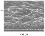
- FIG. 2 A is a side cross-sectional view of a scanning electron microscope (“SEM”) images depicting a conductive film deposited on a silicon substrate to characterize the conductive coating of the engineered particle illustrated in FIG. 1 according to an illustrative embodiment.
- SEM scanning electron microscope
- FIG. 2 B is a top perspective view of a SEM image depicting the conductive film illustrated in FIG. 2 A according to an illustrative embodiment.
- FIG. 3 is a Nyquist plot of the conductive film illustrated in FIGS. 2 A and 2 B according to an illustrative embodiment.
- FIG. 4 is a side cross-sectional view of a lithium ion battery cathode including the engineered particle illustrated in FIG. 1 according to an illustrative embodiment.
- FIGS. 5 A to 5 C depict fabrication steps for fabricating a lithium metal anode including the engineered particle illustrated in FIG. 1 according to an illustrative embodiment.
- FIG. 6 A is a graph showing a charge/discharge voltage profile of a lithium ion battery cell including a cathode which includes the engineered particle illustrated in FIG. 1 and an anode which includes the engineered particle illustrated in FIG. 1 according to an illustrative embodiment.
- FIG. 6 B is a graph showing cell capacity as a function of number of cycles and calculated cycling efficiency for the lithium ion battery cell according to an illustrative embodiment.
- FIG. 7 A is a graph showing a charge/discharge voltage profile of a water battery cell including a cathode which includes the engineered particle illustrated in FIG. 1 and an anode which includes the engineered particle illustrated in FIG. 1 according to an illustrative embodiment.
- FIG. 7 B is a graph showing cell discharge capacity as a function of number of cycles for the water battery cell according to an illustrative embodiment.
- FIG. 8 is a flowchart illustrating a method of fabricating an engineered particle according to an illustrative embodiment.
- an engineered particle and an energy storage device performance enhancer are suitable for use in secondary batteries.
- methods of manufacturing or fabricating the same according to exemplary embodiments are also disclosed here.
- the engineered particle according to an exemplary embodiment is useable in a wide range of applications (for example, different types of secondary batteries or different applications within a same secondary battery). It should be understood that the present disclosure is not limited to the details or methodology set forth in the description or illustrated in the figures. It should also be understood that the terminology used herein is for the purpose of description only and should not be regarded as limiting.
- One challenge with designing secondary batteries or energy storage devices that use active material with a lithium or sodium storage capability is limited lithium or sodium ion conductivity and electrical conductivity of the active material itself that can cause a battery cell to have limited cell performance capability (for example, limited maximum cell capacity that is substantially below theoretical capacity).
- conventional lithium ion batteries have limited cell performance due to limited lithium ion conductivity and limited electrical conductivity of the active material constituting them, such that conventional lithium ion batteries can achieve a maximum cell capacity much less than their theoretical capacity.
- This problem is particularly acute in solid-state lithium ion batteries due to undesirable interactions between solid-state electrolyte particles and active particles that results in poor cell performance.
- the limited cell capacity of solid-state lithium ion batteries remains a significant problem because sufficient ion conduction cannot be achieved in these batteries to allow for a useable solid-state battery cell.
- Conventional solid-state lithium ion batteries suffer from interface resistance between solid-state electrolyte particles and active particles, and this interface resistance results in low cell performance and capacity.
- Lithium metal is desirable for use as an anode in secondary batteries because it is the lightest metal (the density of lithium is 0.59 g cm ⁇ 3 ), because it has a very high theoretical specific capacity (3,820 milliampere per gram (mAh/g)), and because it has the lowest negative electrochemical potential ( ⁇ 3.040 V vs. a standard hydrogen electrode).
- Solid-state secondary batteries have certain advantages over liquid-state secondary batteries. For example, liquid-state batteries suffer from potential flammability issues, which in extreme cases can cause a battery cell to explode. In addition, liquid-state secondary batteries suffer from side-reactions which lead to a shorter lifespan of a battery cell (measured in terms of cycles). Because solid-state secondary batteries do not suffer from these same deficiencies, there is a need for a solid-state secondary battery cell that has good lithium ion conductivity to achieve commercially viable cell capacity and performance.
- the LiCoO 2 particles are coated with a thin film of LiNbO 3 or LSPS using pulsed laser deposition and then used to fabricate a cathode of a solid-state cell, the cell cycled.
- the highest capacity extracted was 95 mAh/g out of 140 mAh/g expected from LiCoO 2 .
- the cell in Sakuda was a powder compressed cell with coated or uncoated LiCoO 2 particles mixed with LSPS particles in the cathode layer, only LSPS particles in the electrolyte layer, and indium-foil as the anode.
- Mari Yamamoto et al. “Binder-free sheet-type all-solid-state batteries with enhanced rate capabilities and high energy densities,” Scientific Reports 8, Article number: 1212 (2018), used LiNbO 3 -coated NMC and a sacrificial binder to fabricate self-sustaining, full all-inorganic solid-state battery cell with a NMC, LSPS, acetylene black-cathode, a LSPS-electrolyte, and a graphite, LSPS, acetylene black anode.
- the sacrificial binder was eliminated during the post fabrication annealing at 300° C. near the glass transition temperature of LSPS.
- the LSPS melted to improve the adhesion and interface between the particles.
- a cell capacity of 155 mAh/g that is much closer to the theoretical capacity of NMC was obtained.
- LiNbO 3 , Li 2 SiO 3 , SiO 2 , and Al 2 O 3 have limited lithium ion conductivity (a conductivity of less than 10 ⁇ 7 Siemens per centimeter (S/cm)).
- an engineered particle that is useable in both liquid-state and solid-state secondary batteries that provides for improved lithium or sodium ion conductivity and reduced interface resistance such that cell performance and cell capacity can be improved in a commercially viable manner.
- an engineered particle which facilitates an intimate contact between a lithium energy storage particle and a lithium ion conducting coating to enhance cell performance. While lithium ion conduction pathways are needed, electron conduction pathways are also important for cell performance, and there is also a need to achieve a desired level of intimacy between the electron conduction pathways and the lithium energy storage particle.
- an engineered particle for use for example in a secondary battery.
- the engineered particle stores alkali ions, has enhanced alkali ion conductivity capability, and enhanced electron conduction capability.
- the alkali ions are lithium ions or sodium ions.
- An engineered particle can include an active particle configured to store energy equal to or at least 90% of what is theoretically possible.
- the active particle is configured to store energy equal to between 90-95% of theoretical energy storage capability.
- the active particle is configured to store energy equal to about to about 95-99% of theoretical energy storage.
- the active particle is configured to store energy equal to about to more than 99% of theoretical energy storage.
- an engineered particle may store energy equal to less than 90% of the theoretical energy storage.
- an engineered particle (e.g., engineered composite particle) 100 according to an exemplary embodiment of the present disclosure is shown.
- the engineered particle 100 includes an active material particle 120 and an alkali ion conducting coating (e.g., conductive coating) 160 disposed around an outer surface of the active material particle.
- the engineered particle 100 also includes electrically conductive carbon nano-particles 140 disposed within the conductive coating 160 .
- the alkali is lithium or sodium.
- the active material particle 120 of the engineered particle 100 has lithium or sodium ion storage capability, for example, the active material particle 120 includes either or both of a lithium intercalating material and sodium intercalating material.
- the active material particle may be formed of any one of the following compounds: LiCoO 2 , LiNiCoAlO 2 , LiNiMnCoO 2 , LiFePO 4 , LiMnO 2 , sulfur, silicon nanoparticle, SiO 2 (such as porous SiO 2 ), SnO 2 , Li 4 Ti 5 O 12 , graphite, graphene oxide, or activated carbon.
- the active material particle 120 may include NaCoO 2 , NaNiCoAlO 2 , NaNiMnCoO 2 , NaFePO 4 , NaMnO 2 , SnO 2 , Na 4 Ti 5 O 12 , sulfur, graphite, graphene oxide, or activated carbon.
- the active material particle 120 of the engineered particle 100 includes a non-lithium intercalating material or a non-sodium intercalating material.
- the active material particle 120 of the engineered particle 100 may include an intercalating material comprised of graphite, activated carbon, graphene oxide, sulfur, SiO 2 (such as porous SiO 2 ), or SnO 2 .
- the active material particle 120 may have any suitable size. As one example, the active material particle 120 has a size of less than 1 ⁇ m. As another example, the active material particle 120 has a size of between about 0.01 ⁇ m and about 50 ⁇ m. As a specific example, the active material particle has a size of about 0.01 ⁇ m.
- the conductive coating 160 includes a M x Al y Si z O w film disposed on the outer surface of the active material particle 120 wherein 1 ⁇ x ⁇ 4, 0 ⁇ y ⁇ 1, 1 ⁇ z ⁇ 2, and 3 ⁇ w ⁇ 6, where M is an alkali metal.
- M is lithium
- the conductive coating includes a Li x Al y Si z O w film.
- M is sodium
- the M x Al y Si z O w film can have any desired thickness.
- the M x Al y Si z O w film can have a thickness of 0.01 ⁇ m to 0.1 ⁇ m.
- a Li x Al y Si z O w film according to an exemplary embodiment has a lithium ion conductivity of about 10 ⁇ 5 S/cm, as can be appreciated from FIG. 3 .
- the conductive coating 160 can be characterized by depositing the film on platinum or gold coated Si substrate, serving as bottom contact, and another platinum or gold top contact deposited on the M x Al y Si z O w film.
- a M x Al y Si z O w film is amorphous, having no crystal with grain boundaries that could block easy flow of ions.
- the conductive coating 160 as presently described is useable in a wide range of surface variability of the active particle because the conductive coating 160 takes the shape of the active material particle 120 it is coating.
- the electrically conductive carbon nano-particles 140 are disposed (e.g., embedded) within the conductive coating 160 .
- the electrically conductive carbon nano-particles 140 can be any carbon nano-particle that allows for electron conductivity (for example, conductive carbon black particles (Super P), graphene, or carbon nanotube).
- the carbon nano-particles have a conductivity within a range of between about 3 S/cm to about 100 S/cm.
- the engineered particle 100 is useable in many different applications, such as in different types of secondary batteries. Because lithium cannot be transformed into an engineered particle (due to lithium's melting temperature of around 160° C.), the lithium metal can be protected with the engineered particle 100 to render the lithium suitable for use in a secondary battery component. On the other hand, graphite can be transformed into an engineered particle because its melting temperature is above 1000° C. Additionally, the engineered particle 100 is useable in different applications in secondary batteries or supercapacitors, for example, in either a cathode or an anode or both, as is further described herein. It is to be understood that the applications described herein are not limiting but are merely exemplary uses for the engineered particle 100 herein disclosed and described.
- the method 800 includes the step 810 of providing one or more active material particles into a solution, each of the one or more active material particles having a predetermined size.
- the predetermined size is within the range of about 0.01 ⁇ m and about 50 though other sizes may also be used.
- the predetermined size of the one or more active material particles can be achieved using any suitable process, for example, by ball milling the one or more active material particles.
- the solution can be any suitable solution, for example, an aqueous solution including an alkali salt and an aluminum salt dissolved in deionized water.
- the solution includes LiNO 3 and Al(NO 3 ) 3 dissolved in deionized water.
- the solution includes NaNO 3 and Al(NO 3 ) 3 dissolved in deionized water.
- the method 800 also includes the step 820 of forming a slurry of the solution and the one or more active material particles.
- the forming of the slurry can include boiling the solution.
- the method 800 also includes the step 830 of introducing a silicate (for example, a water soluble alkali silicate) into the slurry.
- the silicate is a diluted lithium silicate or a diluted sodium silicate.
- the method 800 also includes the step 840 of introducing one or more electrically conductive carbon nano-particles to the slurry.
- the carbon nano-particles can be, for example, conductive carbon black particles (Super P), graphene particles, or carbon nanotubes.
- the method 800 also includes the step 850 of sonicating the slurry to produce a gel.
- the gel can be optionally diluted with deionized water.
- the method 800 also includes the step 860 of forming dry green coated particles from the gel by, for example, transferring the gel to a spray atomizer machine and atomizing the gel to produce the dry green coated particles.
- the method 800 also includes the step 870 of heat treating the dry green coated particles to produce the engineered particle illustrated in FIG. 1 .
- the step 870 of heat treating the dry green coated particles includes curing at a curing temperature of about 300° C. and annealing at an annealing temperature within a range of 400 to 600° C. in the presence of an ambient gas, for example, nitrogen or argon gas.
- an ambient gas for example, nitrogen or argon gas.
- the engineered particle 100 described above can be used in fabricating an electrode for use in a liquid-state alkali ion battery.
- a cathode 200 of a lithium alkali ion battery includes an engineered alkali-intercalating composite material (e.g. LiCoO 2 ) including one or more of the engineered particle 100 of the present disclosure.
- the cathode 200 also includes a metal substrate 220 .
- the substrate is an aluminum substrate.
- FIG. 4 shows the cross-sectional SEM image of an engineered LiCoO 2 cathode post-processing, according to an exemplary embodiment.
- a slurry is formed by blending engineered particles, conductive particles, an organic binder, and a non-aqueous solvent.
- a slurry according to an exemplary embodiment is formed as follows: starting with 90% engineered particle, 5% conductive carbon black particles (Super P), and 5% PVDF (polyvinylidene fluoride or polyvinylidene difluoride) by weight, every 1 g of PVDF is first dissolved in 12 mL of tetrahydrofuran; then every 2 g of total initial solids require 12 mL of a non-aqueous solvent, preferably methoxy propanol, N-methyl pyrrolidone, dimethylformamide, or dimethyl sulfoxide.
- a non-aqueous solvent preferably methoxy propanol, N-methyl pyrrolidone, dimethylformamide, or dimethyl sulfoxide.
- the slurry may also include one or more other particles or other ingredients.
- the coating of the metal substrate by the slurry can be done by spray coating, or slot coating. In some embodiments, coating includes heating the substrate between 80 and 200° C. in air. In some embodiments, for slot coating, no further dilution of the slurry is needed. However, for spray coating the slurry is further diluted to prevent the spray nozzle from getting clogged, preferably increasing the amount of the non-aqueous solvent to a range of about 25 to 50 mL per 2 g of solids.
- the coated aluminum substrate is calendared at about 10-100 tons (for example, at 24 tons, as illustrated in FIG. 4 ). In some embodiments, calendaring is done at about 20-40 tons.
- the coated substrate is then cured at 300° C. in nitrogen ambient. In some embodiments, the coated substrate is cured for 10 to 30 minutes.
- the cathode 200 is useable in lithium or sodium ion battery cells, in either liquid-state or solid-state lithium or sodium ion batteries.
- the engineered particle 100 described above can be used in fabricating an electrode for us in a solid-state lithium ion battery.
- the composite cathode for a solid-state lithium ion battery includes 85% engineered particle, 5 to 10% inorganic solid-state electrolyte nano-particles, and 5% carbon black particles (Super P), though other percentages may be used in other embodiments.
- Mixed powder forming the composite material can be deposited by aerosol deposition on appropriate current collector if a particle size is between 200 nm to 2 ⁇ m to form a dense film.
- LIPON solid-state electrolyte deposition can be accomplished via sputtering, and lithium anode deposition via evaporation to complete the solid-state lithium ion battery cell.
- the electrolyte deposited on the cathode may also be SPEED deposited LiAlGaSPO, according to the deposition processes disclosed in either U.S. Pat. Nos. 8,349,498 and 8,372,163, both of which are incorporated herein by reference in their entireties for all purposes.
- lithium is desirable for use in secondary batteries as an anode because of its light weight and its high specific capacity. These properties allow batteries to achieve high specific energy density (more than 200 Wh/kg).
- the lithium metal anode can be used with any suitable cathode material, including cathodes formed with lithium containing compounds, such as LiCoO 2 , LiFePO 4 , etc., and cathodes formed with non-lithium containing compounds (for example, sulfur cathodes).
- the potential for a lithium anode is limited by the destructive interaction with liquid or polymer electrolyte leading to solid electrolyte interphase (“SEI”) layer formation and buildup.
- SEI solid electrolyte interphase
- the engineered particle 100 herein described in a lithium metal anode can reduce or eliminate the destructive interaction in a lithium ion battery cell.
- the engineered particle includes a lithium-intercalating material such as a lithium aluminosilicate.
- the process 300 includes step 310 of providing a metal current collector.
- the current collector is a mesh or foil.
- the metal current collector is copper, nickel, or stainless steel.
- the process 300 also includes step 320 of laminating the metal current collector with a very thin lithium metal foil.
- the lithium metal can also be evaporated on to the metal current collector.
- the flexibility of the resulting anode is determined by the thickness of the starting metal current collector (e.g., 10 ⁇ m to 100 ⁇ m) and the thickness of the lithium laminate (e.g., 5 ⁇ m to 50 ⁇ m).
- the process 300 also includes the step 340 of spray coating the lithium laminated current collector with a slurry of engineered particles and curing at temperature ranging, for example, from 100 to 300° C.
- the engineered particles can be, for example, SnO 2 engineered particles, Li 4 Ti 5 O 12 engineered particles, graphene oxide engineered particles, or SiO 2 engineered particles.
- the engineered particle can be an active material particle comprising a conductive coating, for example, an alkali-intercalating material having a conductive coating including an alkali aluminosilicate and carbon nanoparticles.
- the slurry can also include hexane, polyisobutylene (PIB) dispersant, engineered particles, and carbon black (Super P conductive carbon).
- the solid content of the slurry is 80 to 90% engineered particles, 5 to 10% Super carbon black, and 5 to 10% PIB.
- toluene benzene is used.
- an engineered LiCoO 2 composite cathode as described herein can be paired with a lithium stabilized anode with a LiPF 6 liquid electrolyte cell with a celgard separator.
- the battery cell exhibits an excellent LiCoO 2 charge/discharge voltage profile.
- the cell can cycle for more than 150 cycles with less than 2% capacity fade.
- an engineered particle 100 is also useable in water-based lithium or sodium secondary batteries.
- a composite cathode can include either an engineered LiMnO 2 particle or an NaMnO 2 particle, along with conductive carbon particles, carbon nanotubes, and PVDF binder, when paired with a composite anode including one of engineered activated carbon, graphite, conductive carbon particles, carbon nanotubes, graphene, and graphene oxide combined with PVDF binder to form a water-based batteries or capacitors.
- at least one of the anode and cathode includes an engineered particle comprising an active material particle comprising a conductive coating, for example, an alkali-intercalating material having a conductive coating including a M x Al y Si z O w film and carbon nanoparticles.
- M is lithium and conductive coating includes a Li x Al y Si z O w film.
- M is sodium and conductive coating includes a Na x Al y Si z O w film.
- the electrolytes in these water-based battery cells include aqueous electrolytes.
- the electrolytes include deionized water solvent with LiNO 3 , Li 2 SO 4 , NaNO 3 , or Na 2 SO 4 .
- the separator in these water-based battery cells can, for example, be cotton cloth, though one or more other materials may also be used.
- FIG. 7 A an engineered NaMnO 2 cathode/engineered activated anode of a water-based battery cell exhibits an excellent charge/discharge voltage profile.
- FIG. 7 B shows that the water-based battery cell has a lifespan of more than 2500 cycles at charge/discharge duration of 15 minutes, with more than 95% capacity retention. In the example shown in FIG.
- the cathode material comprises engineered NaMnO 2
- the anode comprises engineered activated carbon
- the electrolyte comprises a Na 2 SO 4 solution
- the engineered particle comprises a coating of Na x Al y Si z O w .
- an engineered particle 100 is also useable in non-aqueous lithium or sodium secondary batteries.
- a composite cathode can include either an engineered LiNiMnCoO 2 particle or an NaFePO 4 particle, along with conductive carbon particles, carbon nanotubes, and PVDF binder, when paired with a composite anode including one of engineered graphite, activated carbon, conductive carbon particles, graphene oxide, graphene, and carbon nanotubes, combined with PVDF binder to form a non-aqueous batteries or capacitors.
- the composite anode can include Li or Na foil protected by particulate material selected from SnO 2 , Li 4 Ti 5 O 12 , graphite, or SiO 2 .
- At least one of the anode and cathode includes an engineered particle comprising an active material particle comprising a conductive coating, for example, an alkali-intercalating material having a conductive coating including a M x Al y Si z O w film and carbon nanoparticles.
- M is lithium and conductive coating includes a Li x Al y Si z O w film.
- M is sodium and conductive coating includes a Na x Al y Si z O w film.
- the separator is a porous polymeric membrane such as polyethylene, polypropylene, polyimide, or cellulose.
- the electrolytes in these battery cells include non-aqueous electrolytes.
- the electrolytes include one of LiPF 6 , NaPF 6 , LiFSI, and NaFSI, dissolved in ethyl carbonate/ethyl methyl carbonate.
- the electrolytes include ionic liquids.
Landscapes
- Chemical & Material Sciences (AREA)
- Chemical Kinetics & Catalysis (AREA)
- Electrochemistry (AREA)
- General Chemical & Material Sciences (AREA)
- Engineering & Computer Science (AREA)
- Manufacturing & Machinery (AREA)
- Materials Engineering (AREA)
- Inorganic Chemistry (AREA)
- Composite Materials (AREA)
- Crystallography & Structural Chemistry (AREA)
- Power Engineering (AREA)
- Microelectronics & Electronic Packaging (AREA)
- Battery Electrode And Active Subsutance (AREA)
- Secondary Cells (AREA)
- Electric Double-Layer Capacitors Or The Like (AREA)
- Cell Electrode Carriers And Collectors (AREA)
- Cell Separators (AREA)
Abstract
Description
Claims (33)
Priority Applications (2)
| Application Number | Priority Date | Filing Date | Title |
|---|---|---|---|
| US17/066,130 US11894547B2 (en) | 2019-10-08 | 2020-10-08 | Multifunctional engineered particle for a secondary battery and method of manufacturing the same |
| US18/177,350 US12021229B2 (en) | 2019-10-08 | 2023-03-02 | Multifunctional engineered particle for a secondary battery and method of manufacturing the same |
Applications Claiming Priority (3)
| Application Number | Priority Date | Filing Date | Title |
|---|---|---|---|
| US201963101243P | 2019-10-08 | 2019-10-08 | |
| US202063086400P | 2020-10-01 | 2020-10-01 | |
| US17/066,130 US11894547B2 (en) | 2019-10-08 | 2020-10-08 | Multifunctional engineered particle for a secondary battery and method of manufacturing the same |
Related Child Applications (1)
| Application Number | Title | Priority Date | Filing Date |
|---|---|---|---|
| US18/177,350 Division US12021229B2 (en) | 2019-10-08 | 2023-03-02 | Multifunctional engineered particle for a secondary battery and method of manufacturing the same |
Publications (2)
| Publication Number | Publication Date |
|---|---|
| US20210104738A1 US20210104738A1 (en) | 2021-04-08 |
| US11894547B2 true US11894547B2 (en) | 2024-02-06 |
Family
ID=75275248
Family Applications (2)
| Application Number | Title | Priority Date | Filing Date |
|---|---|---|---|
| US17/066,130 Active 2041-05-01 US11894547B2 (en) | 2019-10-08 | 2020-10-08 | Multifunctional engineered particle for a secondary battery and method of manufacturing the same |
| US18/177,350 Active US12021229B2 (en) | 2019-10-08 | 2023-03-02 | Multifunctional engineered particle for a secondary battery and method of manufacturing the same |
Family Applications After (1)
| Application Number | Title | Priority Date | Filing Date |
|---|---|---|---|
| US18/177,350 Active US12021229B2 (en) | 2019-10-08 | 2023-03-02 | Multifunctional engineered particle for a secondary battery and method of manufacturing the same |
Country Status (6)
| Country | Link |
|---|---|
| US (2) | US11894547B2 (en) |
| EP (1) | EP4042506A1 (en) |
| JP (1) | JP2022552267A (en) |
| KR (1) | KR20220116144A (en) |
| CN (1) | CN114788064A (en) |
| WO (1) | WO2021072086A1 (en) |
Families Citing this family (5)
| Publication number | Priority date | Publication date | Assignee | Title |
|---|---|---|---|---|
| JP7677819B2 (en) * | 2021-03-26 | 2025-05-15 | Tdk株式会社 | Lithium-ion secondary battery |
| EP4367727A1 (en) * | 2021-07-08 | 2024-05-15 | Basf Se | Electrochemical cells and electrode active materials suitable for such electrochemical cells |
| CN114014293B (en) * | 2021-11-05 | 2023-09-19 | 四川龙蟒磷化工有限公司 | Preparation method of sodium ion battery material |
| GB2620391A (en) * | 2022-07-04 | 2024-01-10 | Petroliam Nasional Berhad Petronas | Lithium battery |
| CN115084480B (en) * | 2022-07-19 | 2023-09-01 | 成都大学 | A kind of metal oxide-metal sulfide heterojunction material and its preparation method and application |
Citations (11)
| Publication number | Priority date | Publication date | Assignee | Title |
|---|---|---|---|---|
| US20100221613A1 (en) | 2007-10-18 | 2010-09-02 | Tomoyoshi Ueki | Coated positive electrode active material, positive electrode for nonaqueous secondary battery, nonaqueous secondary battery, and their production methods |
| US20100230632A1 (en) * | 2005-09-20 | 2010-09-16 | Virtic, Llc | High energy battery materials |
| US20110215280A1 (en) * | 2010-03-03 | 2011-09-08 | 3M Innovative Properties Company | Composite negative electrode materials |
| US8349498B2 (en) | 2010-01-12 | 2013-01-08 | Sisom Thin Films, Llc | Method of forming solid state electrolyte having high lithium ion conduction and battery incorporating same |
| US20140346618A1 (en) * | 2013-05-23 | 2014-11-27 | Nexeon Limited | Surface treated silicon containing active materials for electrochemical cells |
| US20160049646A1 (en) | 2014-08-15 | 2016-02-18 | Samsung Electronics Co., Ltd. | Lithium secondary battery and method of preparing the same |
| US20160308217A1 (en) | 2013-12-06 | 2016-10-20 | E. I. Du Pont De Nemours And Company | Polyimide coated lithium titanate particles and use thereof in a lithium ion battery |
| US20170133711A1 (en) | 2014-07-01 | 2017-05-11 | I-Ten | All-solid battery including a solid electrolyte and a layer of polymer material |
| US20180175390A1 (en) * | 2016-12-16 | 2018-06-21 | 3M Innovative Properties Company | Anode materials for lithium ion batteries and methods of making and using same |
| US20180212233A1 (en) | 2017-01-24 | 2018-07-26 | Samsung Electronics Co., Ltd. | Composite cathode active material and secondary battery including the same |
| JP2018198131A (en) | 2017-05-23 | 2018-12-13 | 本田技研工業株式会社 | Lithium ion secondary battery |
Family Cites Families (3)
| Publication number | Priority date | Publication date | Assignee | Title |
|---|---|---|---|---|
| US20090253025A1 (en) * | 2008-04-07 | 2009-10-08 | Carnegie Mellon University | Sodium ion based aqueous electrolyte electrochemical secondary energy storage device |
| US10586982B2 (en) * | 2017-08-01 | 2020-03-10 | Global Graphene Group, Inc. | Alkali metal-sulfur secondary battery containing a hybrid anode |
| US10797313B2 (en) * | 2017-12-05 | 2020-10-06 | Global Graphene Group, Inc. | Method of producing anode or cathode particulates for alkali metal batteries |
-
2020
- 2020-10-08 CN CN202080085018.XA patent/CN114788064A/en not_active Withdrawn
- 2020-10-08 KR KR1020227014656A patent/KR20220116144A/en not_active Abandoned
- 2020-10-08 WO PCT/US2020/054798 patent/WO2021072086A1/en unknown
- 2020-10-08 JP JP2022521253A patent/JP2022552267A/en not_active Withdrawn
- 2020-10-08 US US17/066,130 patent/US11894547B2/en active Active
- 2020-10-08 EP EP20874570.3A patent/EP4042506A1/en not_active Withdrawn
-
2023
- 2023-03-02 US US18/177,350 patent/US12021229B2/en active Active
Patent Citations (12)
| Publication number | Priority date | Publication date | Assignee | Title |
|---|---|---|---|---|
| US20100230632A1 (en) * | 2005-09-20 | 2010-09-16 | Virtic, Llc | High energy battery materials |
| US20100221613A1 (en) | 2007-10-18 | 2010-09-02 | Tomoyoshi Ueki | Coated positive electrode active material, positive electrode for nonaqueous secondary battery, nonaqueous secondary battery, and their production methods |
| US8349498B2 (en) | 2010-01-12 | 2013-01-08 | Sisom Thin Films, Llc | Method of forming solid state electrolyte having high lithium ion conduction and battery incorporating same |
| US8372163B2 (en) | 2010-01-12 | 2013-02-12 | Sisom Thin Films, Llc | Method of forming solid state electrolyte having high lithium ion conduction and battery incorporating same |
| US20110215280A1 (en) * | 2010-03-03 | 2011-09-08 | 3M Innovative Properties Company | Composite negative electrode materials |
| US20140346618A1 (en) * | 2013-05-23 | 2014-11-27 | Nexeon Limited | Surface treated silicon containing active materials for electrochemical cells |
| US20160308217A1 (en) | 2013-12-06 | 2016-10-20 | E. I. Du Pont De Nemours And Company | Polyimide coated lithium titanate particles and use thereof in a lithium ion battery |
| US20170133711A1 (en) | 2014-07-01 | 2017-05-11 | I-Ten | All-solid battery including a solid electrolyte and a layer of polymer material |
| US20160049646A1 (en) | 2014-08-15 | 2016-02-18 | Samsung Electronics Co., Ltd. | Lithium secondary battery and method of preparing the same |
| US20180175390A1 (en) * | 2016-12-16 | 2018-06-21 | 3M Innovative Properties Company | Anode materials for lithium ion batteries and methods of making and using same |
| US20180212233A1 (en) | 2017-01-24 | 2018-07-26 | Samsung Electronics Co., Ltd. | Composite cathode active material and secondary battery including the same |
| JP2018198131A (en) | 2017-05-23 | 2018-12-13 | 本田技研工業株式会社 | Lithium ion secondary battery |
Non-Patent Citations (7)
| Title |
|---|
| "From Gems to Lithium Battery Electrodes: The Significance of the Diamond, Ruby (Sapphire), Spinel and Peridot Structures", Thackeray, Argonne National Laboratory, 10th International Meeting on Lithium Batteries, Como, Italy, May 28-Jun. 2, 2000. * |
| Cho, et al., "Novel LiCoO2 Cathode Material with Al2O3 Coating for a Li Ion Cell," Chem. Mater, Nov. 28, 2000, 12, pp. 3788-3791 (4 pages). |
| International Search Report and Written Opinion dated Feb. 17, 2021 received in related PCT/US20/54798 filed Oct. 8, 2020 (11 pages). |
| Sakuda et al., "All-solid-state lithium secondary batteries using LiCoO2 particles with pulsed laser deposition coatings of Li2S—P2S5 solid electrolytes," Journal of Power Sources vol. 196, Issue 16, Aug. 15, 2011, pp. 6735-6741 (7 pages). |
| Sakuda, et al., "Modification of Interface Between LiCoO2 Electrode and Li2S—P2S5 Solid Electrolyte Using Li2O—SiO2 Glassy Layers," J. Electrochem. Soc. 2009 156(1): A27-A32 (6 pages). |
| Xu, et al., "Lithium metal anodes for rechargeable batteries," Energy & Environmental Science, © The Royal Society of Chemistry, 2014, 7, pp. 513-537 (25 pages). |
| Yamamoto, et al., "Binder-free sheet-type all-solid-state batteries with enhanced rate capabilities and high energy densities," Scientific Reports, 8:1212, Jan. 19, 2018 (10 pages). |
Also Published As
| Publication number | Publication date |
|---|---|
| CN114788064A (en) | 2022-07-22 |
| US20210104738A1 (en) | 2021-04-08 |
| WO2021072086A1 (en) | 2021-04-15 |
| US20230216038A1 (en) | 2023-07-06 |
| KR20220116144A (en) | 2022-08-22 |
| EP4042506A1 (en) | 2022-08-17 |
| US12021229B2 (en) | 2024-06-25 |
| JP2022552267A (en) | 2022-12-15 |
Similar Documents
| Publication | Publication Date | Title |
|---|---|---|
| US12021229B2 (en) | Multifunctional engineered particle for a secondary battery and method of manufacturing the same | |
| JP4777593B2 (en) | Method for producing lithium ion secondary battery | |
| CN111137919B (en) | Doped Titanium Niobate and Batteries | |
| US11923532B2 (en) | Pre-lithiated silicon-based anode, and manufacturing method thereof | |
| US20150056387A1 (en) | Methods for making coated porous separators and coated electrodes for lithium batteries | |
| JP4834030B2 (en) | Positive electrode for lithium secondary battery and lithium secondary battery using the same | |
| JP4575487B2 (en) | Lithium ion secondary battery and manufacturing method thereof | |
| CN102449811A (en) | Lithium secondary battery having high energy density | |
| CN108448055A (en) | Lithium-ion battery cathode material and preparation method thereof | |
| JPWO2011052533A1 (en) | Lithium secondary battery | |
| US20220367845A1 (en) | Positive electrode material and battery | |
| JP6674072B1 (en) | Current collecting layer for all-solid-state battery, all-solid-state battery, and carbon material | |
| CN109904404B (en) | Lithium secondary battery negative active material, preparation method thereof and lithium secondary battery containing same | |
| KR20190110347A (en) | Separator Having Coating Layer of Lithium-Containing Composite, and Lithium Secondary Battery Comprising the Separator and Preparation Method Thereof | |
| CN107240718A (en) | Solid state battery and preparation method thereof | |
| KR20130069432A (en) | Coating of disordered carbon active material using water-based binder slurry | |
| WO2021195881A1 (en) | Negative pole piece and electrochemical device containing same | |
| CN116799166A (en) | Negative active material, method of preparing the same, and device including the same | |
| CN116097463A (en) | Negative electrode and secondary battery including said negative electrode | |
| US20150349341A1 (en) | Negative electrode material, negative electrode for lithium ion secondary battery, lithium ion secondary battery, and manufacturing method thereof | |
| JP2011044252A (en) | Lithium ion secondary battery, and electrode for lithium ion secondary battery | |
| JP2010056093A (en) | Lithium ion secondary battery | |
| HK40077360A (en) | Multifunctional engineered particle for a secondary battery and method of manufacturing the same | |
| JP2003242979A (en) | Electrode material and lithium battery using the same | |
| CN111527628A (en) | Electrochemical pretreatment method for vanadium positive electrode for lithium secondary battery and vanadium positive electrode for lithium secondary battery pretreated by said method |
Legal Events
| Date | Code | Title | Description |
|---|---|---|---|
| FEPP | Fee payment procedure |
Free format text: ENTITY STATUS SET TO UNDISCOUNTED (ORIGINAL EVENT CODE: BIG.); ENTITY STATUS OF PATENT OWNER: LARGE ENTITY |
|
| STPP | Information on status: patent application and granting procedure in general |
Free format text: APPLICATION DISPATCHED FROM PREEXAM, NOT YET DOCKETED |
|
| AS | Assignment |
Owner name: SISOM THIN FILMS LLC, FLORIDA Free format text: ASSIGNMENT OF ASSIGNORS INTEREST;ASSIGNORS:OLADEJI, ISAIAH O.;SUZUKI, AKIYOSHI;SUU, KOUKOU;SIGNING DATES FROM 20201008 TO 20201017;REEL/FRAME:054509/0804 Owner name: ULVAC TECHNOLOGIES, INC., MASSACHUSETTS Free format text: ASSIGNMENT OF ASSIGNORS INTEREST;ASSIGNORS:OLADEJI, ISAIAH O.;SUZUKI, AKIYOSHI;SUU, KOUKOU;SIGNING DATES FROM 20201008 TO 20201017;REEL/FRAME:054509/0804 |
|
| STPP | Information on status: patent application and granting procedure in general |
Free format text: DOCKETED NEW CASE - READY FOR EXAMINATION |
|
| STPP | Information on status: patent application and granting procedure in general |
Free format text: NON FINAL ACTION MAILED |
|
| STPP | Information on status: patent application and granting procedure in general |
Free format text: RESPONSE TO NON-FINAL OFFICE ACTION ENTERED AND FORWARDED TO EXAMINER |
|
| STPP | Information on status: patent application and granting procedure in general |
Free format text: NON FINAL ACTION MAILED |
|
| STPP | Information on status: patent application and granting procedure in general |
Free format text: NON FINAL ACTION MAILED |
|
| STPP | Information on status: patent application and granting procedure in general |
Free format text: RESPONSE TO NON-FINAL OFFICE ACTION ENTERED AND FORWARDED TO EXAMINER |
|
| STPP | Information on status: patent application and granting procedure in general |
Free format text: NOTICE OF ALLOWANCE MAILED -- APPLICATION RECEIVED IN OFFICE OF PUBLICATIONS |
|
| STPP | Information on status: patent application and granting procedure in general |
Free format text: PUBLICATIONS -- ISSUE FEE PAYMENT VERIFIED |
|
| STCF | Information on status: patent grant |
Free format text: PATENTED CASE |