US11882556B2 - Transmission of physical uplink channels and signals for new radio beamformed system - Google Patents
Transmission of physical uplink channels and signals for new radio beamformed system Download PDFInfo
- Publication number
- US11882556B2 US11882556B2 US17/282,931 US201917282931A US11882556B2 US 11882556 B2 US11882556 B2 US 11882556B2 US 201917282931 A US201917282931 A US 201917282931A US 11882556 B2 US11882556 B2 US 11882556B2
- Authority
- US
- United States
- Prior art keywords
- transmission
- puch
- pucch
- pusch
- priority
- Prior art date
- Legal status (The legal status is an assumption and is not a legal conclusion. Google has not performed a legal analysis and makes no representation as to the accuracy of the status listed.)
- Active, expires
Links
- 230000005540 biological transmission Effects 0.000 title claims abstract description 273
- 238000012545 processing Methods 0.000 claims description 13
- 230000000737 periodic effect Effects 0.000 claims description 8
- 238000000034 method Methods 0.000 description 50
- 238000004891 communication Methods 0.000 description 15
- 230000006870 function Effects 0.000 description 8
- 230000008569 process Effects 0.000 description 6
- 239000000969 carrier Substances 0.000 description 3
- 238000007726 management method Methods 0.000 description 3
- 238000013507 mapping Methods 0.000 description 3
- 230000002093 peripheral effect Effects 0.000 description 3
- 101710141933 Single-stranded DNA-binding protein 1 Proteins 0.000 description 2
- 230000010267 cellular communication Effects 0.000 description 2
- 230000008878 coupling Effects 0.000 description 2
- 238000010168 coupling process Methods 0.000 description 2
- 238000005859 coupling reaction Methods 0.000 description 2
- 230000003247 decreasing effect Effects 0.000 description 2
- 238000001514 detection method Methods 0.000 description 2
- 238000010586 diagram Methods 0.000 description 2
- 238000005516 engineering process Methods 0.000 description 2
- 238000010295 mobile communication Methods 0.000 description 2
- 230000004044 response Effects 0.000 description 2
- 230000008901 benefit Effects 0.000 description 1
- 230000001413 cellular effect Effects 0.000 description 1
- 230000001427 coherent effect Effects 0.000 description 1
- 230000007274 generation of a signal involved in cell-cell signaling Effects 0.000 description 1
- 239000011159 matrix material Substances 0.000 description 1
- 230000007246 mechanism Effects 0.000 description 1
- 238000012986 modification Methods 0.000 description 1
- 230000004048 modification Effects 0.000 description 1
- 238000012913 prioritisation Methods 0.000 description 1
- 230000011664 signaling Effects 0.000 description 1
- 230000003068 static effect Effects 0.000 description 1
Images


Classifications
-
- H—ELECTRICITY
- H04—ELECTRIC COMMUNICATION TECHNIQUE
- H04W—WIRELESS COMMUNICATION NETWORKS
- H04W72/00—Local resource management
- H04W72/12—Wireless traffic scheduling
- H04W72/1263—Mapping of traffic onto schedule, e.g. scheduled allocation or multiplexing of flows
- H04W72/1268—Mapping of traffic onto schedule, e.g. scheduled allocation or multiplexing of flows of uplink data flows
-
- H—ELECTRICITY
- H04—ELECTRIC COMMUNICATION TECHNIQUE
- H04B—TRANSMISSION
- H04B7/00—Radio transmission systems, i.e. using radiation field
- H04B7/02—Diversity systems; Multi-antenna system, i.e. transmission or reception using multiple antennas
- H04B7/04—Diversity systems; Multi-antenna system, i.e. transmission or reception using multiple antennas using two or more spaced independent antennas
- H04B7/0408—Diversity systems; Multi-antenna system, i.e. transmission or reception using multiple antennas using two or more spaced independent antennas using two or more beams, i.e. beam diversity
-
- H—ELECTRICITY
- H04—ELECTRIC COMMUNICATION TECHNIQUE
- H04B—TRANSMISSION
- H04B7/00—Radio transmission systems, i.e. using radiation field
- H04B7/02—Diversity systems; Multi-antenna system, i.e. transmission or reception using multiple antennas
- H04B7/04—Diversity systems; Multi-antenna system, i.e. transmission or reception using multiple antennas using two or more spaced independent antennas
- H04B7/06—Diversity systems; Multi-antenna system, i.e. transmission or reception using multiple antennas using two or more spaced independent antennas at the transmitting station
- H04B7/0613—Diversity systems; Multi-antenna system, i.e. transmission or reception using multiple antennas using two or more spaced independent antennas at the transmitting station using simultaneous transmission
- H04B7/0615—Diversity systems; Multi-antenna system, i.e. transmission or reception using multiple antennas using two or more spaced independent antennas at the transmitting station using simultaneous transmission of weighted versions of same signal
- H04B7/0617—Diversity systems; Multi-antenna system, i.e. transmission or reception using multiple antennas using two or more spaced independent antennas at the transmitting station using simultaneous transmission of weighted versions of same signal for beam forming
-
- H—ELECTRICITY
- H04—ELECTRIC COMMUNICATION TECHNIQUE
- H04L—TRANSMISSION OF DIGITAL INFORMATION, e.g. TELEGRAPHIC COMMUNICATION
- H04L5/00—Arrangements affording multiple use of the transmission path
- H04L5/0001—Arrangements for dividing the transmission path
- H04L5/0003—Two-dimensional division
- H04L5/0005—Time-frequency
- H04L5/0007—Time-frequency the frequencies being orthogonal, e.g. OFDM(A), DMT
- H04L5/001—Time-frequency the frequencies being orthogonal, e.g. OFDM(A), DMT the frequencies being arranged in component carriers
-
- H—ELECTRICITY
- H04—ELECTRIC COMMUNICATION TECHNIQUE
- H04L—TRANSMISSION OF DIGITAL INFORMATION, e.g. TELEGRAPHIC COMMUNICATION
- H04L5/00—Arrangements affording multiple use of the transmission path
- H04L5/003—Arrangements for allocating sub-channels of the transmission path
- H04L5/0044—Arrangements for allocating sub-channels of the transmission path allocation of payload
-
- H—ELECTRICITY
- H04—ELECTRIC COMMUNICATION TECHNIQUE
- H04L—TRANSMISSION OF DIGITAL INFORMATION, e.g. TELEGRAPHIC COMMUNICATION
- H04L5/00—Arrangements affording multiple use of the transmission path
- H04L5/003—Arrangements for allocating sub-channels of the transmission path
- H04L5/0048—Allocation of pilot signals, i.e. of signals known to the receiver
-
- H—ELECTRICITY
- H04—ELECTRIC COMMUNICATION TECHNIQUE
- H04L—TRANSMISSION OF DIGITAL INFORMATION, e.g. TELEGRAPHIC COMMUNICATION
- H04L5/00—Arrangements affording multiple use of the transmission path
- H04L5/003—Arrangements for allocating sub-channels of the transmission path
- H04L5/0053—Allocation of signaling, i.e. of overhead other than pilot signals
- H04L5/0055—Physical resource allocation for ACK/NACK
-
- H—ELECTRICITY
- H04—ELECTRIC COMMUNICATION TECHNIQUE
- H04L—TRANSMISSION OF DIGITAL INFORMATION, e.g. TELEGRAPHIC COMMUNICATION
- H04L5/00—Arrangements affording multiple use of the transmission path
- H04L5/003—Arrangements for allocating sub-channels of the transmission path
- H04L5/0053—Allocation of signaling, i.e. of overhead other than pilot signals
- H04L5/0057—Physical resource allocation for CQI
-
- H—ELECTRICITY
- H04—ELECTRIC COMMUNICATION TECHNIQUE
- H04L—TRANSMISSION OF DIGITAL INFORMATION, e.g. TELEGRAPHIC COMMUNICATION
- H04L5/00—Arrangements affording multiple use of the transmission path
- H04L5/003—Arrangements for allocating sub-channels of the transmission path
- H04L5/0058—Allocation criteria
- H04L5/0064—Rate requirement of the data, e.g. scalable bandwidth, data priority
-
- H—ELECTRICITY
- H04—ELECTRIC COMMUNICATION TECHNIQUE
- H04W—WIRELESS COMMUNICATION NETWORKS
- H04W72/00—Local resource management
- H04W72/04—Wireless resource allocation
- H04W72/044—Wireless resource allocation based on the type of the allocated resource
- H04W72/046—Wireless resource allocation based on the type of the allocated resource the resource being in the space domain, e.g. beams
-
- H—ELECTRICITY
- H04—ELECTRIC COMMUNICATION TECHNIQUE
- H04W—WIRELESS COMMUNICATION NETWORKS
- H04W72/00—Local resource management
- H04W72/50—Allocation or scheduling criteria for wireless resources
- H04W72/56—Allocation or scheduling criteria for wireless resources based on priority criteria
- H04W72/566—Allocation or scheduling criteria for wireless resources based on priority criteria of the information or information source or recipient
- H04W72/569—Allocation or scheduling criteria for wireless resources based on priority criteria of the information or information source or recipient of the traffic information
Definitions
- Embodiments of the present invention relate generally to the technical field of wireless communications.
- NR next generation wireless communication system
- 5G next generation wireless communication system
- NR new radio
- 3GPP LTE-Advanced with additional potential new Radio Access Technologies (RATs) to enrich people lives with better, simple and seamless wireless connectivity solutions.
- RATs Radio Access Technologies
- FIG. 1 illustrates a network in accordance with some embodiments.
- FIG. 2 illustrates two beamforming implementations in accordance with some embodiments.
- FIG. 3 illustrates a transmission scenario in accordance with some embodiments.
- FIG. 4 illustrates a transmission scenario in accordance with some embodiments.
- FIG. 5 illustrates a transmission scenario in accordance with some embodiments.
- FIG. 6 illustrates a transmission scenario in accordance with some embodiments.
- FIG. 7 illustrates an operation flow/algorithmic structure in accordance with some embodiments.
- FIG. 8 is a block diagram illustrating components, according to some example embodiments, able to read instructions from a machine-readable or computer-readable medium (for example, a non-transitory machine-readable storage medium) and perform any one or more of the methodologies discussed herein.
- a machine-readable or computer-readable medium for example, a non-transitory machine-readable storage medium
- FIG. 1 schematically illustrates an example wireless network 100 (hereinafter “network 100 ”) in accordance with various embodiments herein.
- the network 100 may include a UE 105 in wireless communication with an AN 110 .
- the network 100 may be an NR or LTE network.
- the UE 105 may be configured to connect, for example, to be communicatively coupled, with the AN 110 via connection 112 .
- connection 112 is illustrated as an air interface to enable communicative coupling, and can be consistent with cellular communications protocols such as an LTE protocol, a 5G NR protocol operating at mmWave and sub-6 GHz, a Global System for Mobile Communications (GSM) protocol, a code-division multiple access (CDMA) network protocol, a Push-to-Talk (PTT) protocol, and the like.
- cellular communications protocols such as an LTE protocol, a 5G NR protocol operating at mmWave and sub-6 GHz, a Global System for Mobile Communications (GSM) protocol, a code-division multiple access (CDMA) network protocol, a Push-to-Talk (PTT) protocol, and the like.
- GSM Global System for Mobile Communications
- CDMA code-division multiple access
- PTT Push-to-Talk
- the UE 105 is illustrated as a smartphone (for example, a handheld touchscreen mobile computing device connectable to one or more cellular networks), but may also comprise any mobile or non-mobile computing devices, such as a Personal Data Assistant (PDA), pager, laptop computer, desktop computer, wireless handset, customer premises equipment (CPE), fixed wireless access (FWA) device, vehicle mounted UE or any computing device including a wireless communications interface.
- PDA Personal Data Assistant
- CPE customer premises equipment
- FWA fixed wireless access
- vehicle mounted UE vehicle mounted UE or any computing device including a wireless communications interface.
- the UE 105 can comprise an Internet of Things (IoT) UE, which can comprise a network access layer designed for low-power IoT applications utilizing short-lived UE connections.
- IoT Internet of Things
- An IoT UE can utilize technologies such as narrowband IoT (NB-IoT), machine-to-machine (M2M) or machine-type communications (MTC) for exchanging data with an MTC server or device via a public land mobile network (PLMN), Proximity-Based Service (ProSe) or device-to-device (D2D) communication, sensor networks, or IoT networks.
- the M2M or MTC exchange of data may be a machine-initiated exchange of data.
- An NB-IoT/MTC network describes interconnecting NB-IoT/MTC UEs, which may include uniquely identifiable embedded computing devices (within the Internet infrastructure), with short-lived connections.
- the NB-IoT/MTC UEs may execute background applications (for example, keep-alive message, status updates, location related services, etc.).
- the AN 110 can enable or terminate the connection 112 .
- the AN 110 can be referred to as a base station (BS), NodeB, evolved-NodeB (eNB), Next-Generation NodeB (gNB or ng-gNB), NG-RAN node, cell, serving cell, neighbor cell, and so forth, and can comprise ground stations (for example, terrestrial access points) or satellite stations providing coverage within a geographic area.
- BS base station
- eNB evolved-NodeB
- gNB or ng-gNB Next-Generation NodeB
- NG-RAN node cell, serving cell, neighbor cell, and so forth
- ground stations for example, terrestrial access points
- satellite stations providing coverage within a geographic area.
- the AN 110 can be the first point of contact for the UE 105 .
- the AN 110 can fulfill various logical functions including, but not limited to, radio network controller (RNC) functions such as radio bearer management, uplink and downlink dynamic radio resource management and data packet scheduling, and mobility management.
- RNC radio network controller
- the UE 105 may include protocol processing circuitry 115 , which may implement one or more of layer operations related to medium access control (MAC), radio link control (RLC), packet data convergence protocol (PDCP), radio resource control (RRC) and non-access stratum (NAS).
- the protocol processing circuitry 115 may include one or more processing cores (not shown) to execute instructions and one or more memory structures (not shown) to store program and data information.
- the UE 105 may further include digital baseband circuitry 125 , which may implement physical layer (PHY) functions including one or more of hybrid automatic repeat request-acknowledgment (HARQ-ACK) functions, scrambling and/or descrambling, coding and/or decoding, layer mapping and/or de-mapping, modulation symbol mapping, received symbol and/or bit metric determination, multi-antenna port pre-coding and/or decoding, which may include one or more of space-time, space-frequency or spatial coding, reference signal generation and/or detection, preamble sequence generation and/or decoding, synchronization sequence generation and/or detection, control channel signal blind decoding, and other related functions.
- PHY physical layer
- HARQ-ACK hybrid automatic repeat request-acknowledgment
- the UE 105 may further include transmit circuitry 135 , receive circuitry 145 , radio frequency (RF) circuitry 155 , and RF front end (RFFE) 165 , which may include or connect to one or more antenna panels 175 .
- transmit circuitry 135 receive circuitry 145 , radio frequency (RF) circuitry 155 , and RF front end (RFFE) 165 , which may include or connect to one or more antenna panels 175 .
- RF radio frequency
- RFFE RF front end
- circuitry may refer to, is part of, or includes hardware components such as an electronic circuit, a logic circuit, a processor (shared, dedicated, or group) and/or memory (shared, dedicated, or group), an Application Specific Integrated Circuit (ASIC), a field-programmable device (FPD) (e.g., a field-programmable gate array (FPGA), a programmable logic device (PLD), a complex PLD (CPLD), a high-capacity PLD (HCPLD), a structured ASIC, or a programmable System on Chip (SoC)), digital signal processors (DSPs), etc., that are configured to provide the described functionality.
- FPD field-programmable device
- FPGA field-programmable gate array
- PLD programmable logic device
- CPLD complex PLD
- HPLD high-capacity PLD
- SoC programmable System on Chip
- DSPs digital signal processors
- the circuitry may execute one or more software or firmware programs to provide at least some of the described functionality.
- the term “circuitry” may also refer to a combination of one or more hardware elements (or a combination of circuits used in an electrical or electronic system) with the program code used to carry out the functionality of that program code. In these embodiments, the combination of hardware elements and program code may be referred to as a particular type of circuitry.
- RF circuitry 155 may include multiple parallel RF chains or branches for one or more of transmit or receive functions; each chain or branch may be coupled with one antenna panel 175 .
- the protocol processing circuitry 115 may include one or more instances of control circuitry (not shown) to provide control functions for the digital baseband circuitry 125 (or simply, “baseband circuitry 125 ”), transmit circuitry 135 , receive circuitry 145 , radio frequency circuitry 155 , RFFE 165 , and one or more antenna panels 175 .
- a UE reception may be established by and via the one or more antenna panels 175 , RFFE 165 , RF circuitry 155 , receive circuitry 145 , digital baseband circuitry 125 , and protocol processing circuitry 115 .
- the one or more antenna panels 175 may receive a transmission from the AN 110 by receive-beamforming signals received by a plurality of antennas/antenna elements of the one or more antenna panels 175 .
- the transmission from the AN 110 may be transmit-beamformed by antennas of the AN 110 .
- the baseband circuitry 125 may contain both the transmit circuitry 135 and the receive circuitry 145 .
- the baseband circuitry 125 may be implemented in separate chips or modules, for example, one chip including the transmit circuitry 135 and another chip including the receive circuitry 145 .
- the AN 110 may include protocol processing circuitry 120 , digital baseband circuitry 130 (or simply, “baseband circuitry 130 ”), transmit circuitry 140 , receive circuitry 150 , RF circuitry 160 , RFFE 170 , and one or more antenna panels 180 .
- a cell transmission may be established by and via the protocol processing circuitry 120 , digital baseband circuitry 130 , transmit circuitry 140 , RF circuitry 160 , RFFE 170 , and one or more antenna panels 180 .
- the transmission components of the UE 105 may apply a spatial filter to the data to be transmitted to form a transmit beam emitted by the antenna elements of the one or more antenna panels 180 .
- FIG. 2 illustrates two beamforming implementations of the UE 105 in accordance with some embodiments.
- transmit components 204 may represent the components of the UE 105 involved with various beamforming operations. These components may include circuitry from one or more of the protocol processing circuitry 120 , digital baseband circuitry 130 , transmit circuitry 140 , RF circuitry 160 , RFFE 170 , and the one or more antenna panels 180 .
- the transmit components 204 may be configured with a first spatial filter (SF1) 208 or a second spatial filter (SF2) 212 .
- Each spatial filter may represent a set of parameters that may be applied to data/signals that may form a particular transmit beam.
- the parameters could include, but are not limited to, number of antenna elements, structure of antenna elements, phase and amplitude applied to a data/signal path, etc.
- the transmit components 204 may apply SF1 208 to a physical uplink channel (PUCH) transmission to cause the PUCH transmission to be transmitted by a first transmit beam (TX beam 1 ) or may apply SF2 212 to the PUCH transmission to cause the PUCH transmission to be transmitted by a third transmit beam (TX beam 3 ).
- transmitting a PUCH transmission with a particular transmit beam includes applying a spatial filter to data/signals of the PUCH transmission to provide the particular transmit beam.
- the UE 104 may determine spatial filters to be used for a particular PUCH by determining a transmit beam used by the access node 110 .
- the UE 104 may receive a transmission (for example, a synchronization signal block, a CSI/reference signal, etc.) from the access node 110 and determine an associated transmit beam used for the transmission based on an index of the transmission.
- the UE 104 may use this information for spatial filters that may be used for both receive beams to receive the transmission from the access node 110 and transmit beams to be sent to the access node 110 .
- PUCH transmissions may include or otherwise refer to any uplink transmission in physical channels such as a physical uplink control channel (PUCCH), a physical uplink shared channel (PUSCH), a physical random access channel (PRACH).
- PUCCH physical uplink control channel
- PUSCH physical uplink shared channel
- PRACH physical random access channel
- the PUCH transmission may also include or otherwise refer to physical signals transmitted in an uplink channel such as, but not limited to, a sounding reference signal (SRS).
- SRS sounding reference signal
- the PUCCH may primarily be used to carry control information
- the PUSCH may be primarily used to carry application data
- the PRACH may be primarily used for random access.
- uplink control information can be carried by both PUCCH and PUSCH.
- UCI may include scheduling request (SR), hybrid automatic repeat request-acknowledgement (HARQ-ACK) feedback, channel state information (CSI) report, e.g., channel quality indicator (CQI), pre-coding matrix indicator (PMI), CSI resource indicator (CRI) and rank indicator (RI) and/or beam related information (for example, Layer 1-reference signal received power (L1-RSRP)).
- SR scheduling request
- HARQ-ACK hybrid automatic repeat request-acknowledgement
- CSI channel state information
- CQI channel quality indicator
- PMI pre-coding matrix indicator
- CRI rank indicator
- beam related information for example, Layer 1-reference signal received power (L1-RSRP)
- a short duration NR PUCCH may be multiplexed with a PUSCH in a time division multiplexing (TDM) manner. This may be targeted for low latency application.
- TDM time division multiplexing
- multiple OFDM symbols can be allocated for NR PUCCH to improve link budget and uplink coverage for the control channel.
- the NR PUCCH and PUSCH can be multiplexed in a frequency division multiplexing (FDM) fashion.
- FDM frequency division multiplexing
- the UE 105 may be able to form a single transmit (Tx) beam for the transmission of the physical uplink signal or channel.
- Tx transmit
- the UE 105 may be able to only transmit one physical uplink channel or signal for a given time using the single Tx beam.
- Various embodiments describe how to handle such multiplexed uplink transmissions using only one Tx beam.
- embodiments disclosed herein may be directed to mechanisms on handling simultaneous transmission of physical uplink channels and signals for NR beamformed systems. Some embodiments may be directed to: handling PUSCHs scheduled for simultaneous transmission with different Tx beams; handling PUCCHs scheduled for simultaneous transmission with different Tx beams; and handling PUCCH and PUSCH scheduled for simultaneous transmission with different Tx beams.
- the UE 105 may be able to form a single analog Tx beam for the transmission of physical uplink signal or channel for all the CCs (possibly the entire band).
- certain aspects may need to be defined to drop or de-prioritize one or more physical uplink channels/signals and only transmit one physical uplink channel/signal using an indicated or configured Tx beam.
- the UE 105 in a case when the UE 105 does not support simultaneous transmission of more than one physical channel/signal using distinct Tx beams, if a first physical uplink channel/signal and a second physical uplink channel/signal are multiplexed in an FDM manner in different CCs, and if the first and second physical uplink channel/signal are indicated or configured with different spatial relations or quasi-collocated (QCL) assumptions or different Tx beams (which may be collectively referred to as “different spatial filters”), the UE 105 would transmit the physical uplink channel/signal with an earlier starting symbol using the indicated or configured Tx beam. The other physical channel/signal can be dropped or transmitted using the same Tx beam.
- QCL quasi-collocated
- the UE 105 may transmit the physical uplink channel/signal on the serving cell with smallest serving cell index (ServCellIndex) using the indicated or configured Tx beam.
- the other physical channel/signal can be dropped or transmitted using the same Tx beam.
- the same Tx beam may indicate that there is the same downlink reference signal in the spatial relation information chain between two uplink signals/channels, or the downlink reference signals are QCLed with spatial Rx parameters (QCL-typeD).
- QCL-typeD spatial Rx parameters
- the UE 105 may schedule PUSCHs to be simultaneously transmitted with different transmit beams. These situations may be handled as follows.
- the UE 105 may transmit the PUSCH of the serving cell with the smallest ServCellIndex and that is a grant-based PUSCH (for example, scheduled by DCI format(s) 0_0 or DCI format(s) 0_1) using the indicated or configured Tx beam.
- the other PUSCH can be dropped or transmitted using the same Tx beam.
- the PUSCH of the serving cell with the smallest ServCellIndex may be transmitted using the indicated or configured Tx beam.
- the other PUSCH can be dropped or transmitted using the same Tx beam.
- the UE 105 may only transmit the first PUSCH and drop the second PUSCH or the UE 105 would transmit both PUSCH transmissions using the Tx beam that is configured for the first PUSCH.
- the UE 105 may only transmit the first PUSCH and drop the second PUSCH or the UE may transmit both PUSCH transmissions using the Tx beam that is configured for the first PUSCH.
- FIG. 3 illustrates a transmission scenario 300 in which PUSCHs are scheduled for simultaneous transmission with different Tx beams in different CCs in accordance with some embodiments.
- two PUSCH transmissions, PUSCH 304 and PUSCH 308 are with different Tx beams are multiplexed in a FDM manner in PCell and SCell, respectively.
- PUSCH 308 is a configured grant transmission and PUSCH transmission 304 is a grant-based transmission.
- the UE 105 may drop the PUSCH 308 and transmit the PUSCH 304 .
- the UE 105 may transmit the PUSCH 308 with the transmit beam used to transmit PUSCH 304 , that is, Tx beam # 1 . While this beam may not be the most desirable beam for transmission of PUSCH 308 , it may still be effective in some situations.
- the UE 105 in cases when the UE 105 does not support simultaneous transmission of more than one physical channels/signals using distinct Tx beams, if a first PUSCH and a second PUSCH are multiplexed in an FDM manner in different component carriers (CC), if the first and second PUSCH are indicated or configured with different spatial filters, when a UCI is multiplexed on the first PUSCH and a UCI is not multiplexed on the second PUSCH, the UE 105 would only transmit the first PUSCH and drop the second PUSCH or the UE 105 would transmit both PUSCH using the Tx beam that is indicated or configured for the first PUSCH.
- CC component carriers
- the UE 105 when the first and second PUSCHs carry the UCI, the UE 105 would transmit the PUSCH carrying UCI with the highest priority or the UE 105 would transmit both PUSCH using the Tx beam of the PUSCH carrying UCI with the highest priority.
- the priority rule can be defined as HARQ-ACK feedback>SR>CSI with higher priority>CSI with lower priority. If multiple UCI types are carried by a PUSCH, the UCI type with the highest priority may be considered in the dropping rule.
- the PUSCH on the serving cell with smallest serving cell index may be transmitted or both PUSCH may be transmitted using the beam associated with the smallest ServCellIndex PUSCH.
- FIG. 4 illustrates a transmission scenario 400 in which PUSCHs are scheduled for simultaneous transmission with different Tx beams in different CCs in accordance with some embodiments.
- PUSCH 404 in the Scell may not include UCI and may be scheduled for transmission using Tx beam # 1 .
- PUSCH 408 in the PCell may include UCI and may be scheduled for transmission using Tx beam # 2 .
- the PUSCH 408 may be transmitted with Tx beam # 2 and PUSCH 404 may either be dropped or transmitted with Tx beam # 2 .
- PUCCHs may be scheduled to be simultaneously transmitted with different Tx beams. Such scenarios may be handled as follows.
- the UE 105 may drop one of the first and second PUCCH in accordance with a priority rule or UE may transmit first and second PUCCH using the Tx beam of the prioritized PUCCH.
- the priority rule can be defined as HARQ-ACK feedback>SR>CSI with higher priority>CSI with lower priority. If multiple UCI types are carried by a PUCCH, the UCI type with highest priority may be considered in the dropping rule.
- the second PUCCH carrying SR is dropped or transmitted using the Tx beam of the first PUCCH.
- a first PUCCH carrying dynamic HARQ-ACK feedback and a second PUCCH carrying semi-persistent scheduled (SPS) HARQ-ACK feedback are multiplexed in an FDM manner, and the first and second PUCCH are indicated/configured with different beams, the second PUCCH is dropped or transmitted using the Tx beam of the first PUCCH.
- Dynamic HARQ-ACK feedback may correspond to the case where the HARQ-ACK is in response to a physical downlink shared channel (PDSCH) reception scheduled by a corresponding physical downlink control channel (PDCCH).
- PDSCH physical downlink shared channel
- PDCCH physical downlink control channel
- SPS HARQ-ACK feedback may correspond to the case where the HARQ-ACK is in response to a PDSCH reception without an associated PDCCH.
- the PUCCH on PCell is transmitted and the PUCCH on PUCCH SCell is dropped or transmitted using the Tx beam associated with the Pcell PUCCH.
- FIG. 5 illustrates a transmission scenario 500 in which PUCCHs are scheduled for simultaneous transmission with different Tx beams in different CCs in accordance with some embodiments.
- the UE 105 may be configured with two PUCCH groups, PUCCH 504 and PUCCH 508 , where PUCCH is only transmitted in PCell and PUCCH SCell.
- PUCCH 504 may carry HARQ-ACK in the PUCCH Scell and may be scheduled for transmission using Tx beam # 1 .
- PUCCH 508 may carry a CSI report in the Pcell and may be scheduled for transmission using Tx beam # 2 .
- the PUCCH 504 may be transmitted using Tx beam # 1 and PUCCH 508 may be dropped or transmitted using Tx beam # 1 .
- the UE 105 may transmit one of the first and second PUCCH with smaller or larger PUCCH resource ID.
- the other PUCCH may be dropped or transmitted using the same Tx beam.
- the second PUCCH with larger PUCCH resource ID may be dropped or transmitted using the same Tx beam as the first PUCCH with the smaller PUCCH resource ID.
- the PUCCH on the PCell may be transmitted and the PUCCH on the PUCCH SCell may dropped or transmitted using the same Tx beam as the PUCCH on the Pcell.
- a PUSCH and PUCCH may be scheduled to be simultaneously transmitted with different transmit beams. These embodiments are handled as follows.
- the UE 105 may drop the PUCCH and transmit the PUSCH or the UE 105 may transmit both the PUCCH and the PUSCH using the PUSCH Tx beam.
- the UE 105 may drop the PUSCH and transmit the PUCCH or transmit both using the PUCCH transmit beam.
- whether to drop or de-prioritize PUCCH or PUSCH may be configured by higher layers via multicast channel scheduling information (MSI), remaining minimum system information (RMSI), other system information (OSI), or RRC signalling.
- MSI multicast channel scheduling information
- RMSI remaining minimum system information
- OSI system information
- RRC signalling resource control
- the PUSCH may be dropped or de-prioritized and the PUCCH may be transmitted or prioritized.
- the PUSCH is a configured-grant transmission, the PUSCH may be dropped/de-prioritized and the PUCCH may be transmitted/prioritized.
- the UCI carried by the PUCCH includes periodic or semi-persistent CSI report, the PUCCH may be dropped/de-prioritized and PUSCH may be transmitted/prioritized.
- the priority rule can be used to determine whether UE transmits/prioritizes PUCCH or PUSCH.
- the priority rule can be defined as HARQ-ACK feedback>SR>CSI with higher priority>CSI with lower priority. If multiple UCI types are carried by a PUCCH or PUSCH, the UCI type with highest priority is considered in the dropping/de-prioritization rule.
- the PUCCH or PUSCH on the serving cell with smallest ServCellIndex may be transmitted/prioritized.
- FIG. 6 illustrates a transmission scenario 600 in which a PUCCH and PUSCH are scheduled for simultaneous transmission with different Tx beams in different CCs in accordance with some embodiments.
- PUCCH 608 and PUSCH 604 are configured with different Tx beams and are multiplexed in an FDM manner in PCell and PUCCH SCell, respectively.
- the PUSCH 604 is carrying HARQ-ACK and the PUCCH 608 is carrying CSI. Given that the CSI report has lower priority than HARQ-ACK feedback, the PUSCH 604 is transmitted using Tx beam # 1 and the PUCCH 608 , carrying the CSI report, is dropped or transmitted using Tx beam # 1 .
- the priority rule could be defined as follows: PRACH transmission on the PCell>PUCCH transmission with HARQ-ACK information and/or SR or PUSCH transmission with HARQ-ACK information>PUCCH transmission with CSI or PUSCH transmission with CSI>PUSCH transmission without HARQ-ACK information or CSI>SRS transmission, with aperiodic SRS having higher priority than semi-persistent and/or periodic SRS, or PRACH transmission on a serving cell other than the PCell.
- the uplink signal/channel with lowest priority may be dropped if different Tx beams are applied.
- FIG. 7 illustrates an operation flow/algorithmic structure 700 in accordance with some embodiments.
- the operation flow/algorithmic structure 700 may be performed, in part or in whole, by the UE 105 or components thereof.
- the operation flow/algorithmic structure 700 may be performed by transmit components of the UE 105 .
- the operation flow/algorithmic structure 700 may include, at 704 , determining first and second PUCH transmissions are to be transmitted in different component carriers with different spatial filters.
- the PUCH transmissions may be scheduled (or otherwise determined) to be multiplexed in frequency with one another.
- the PUCH transmissions may be PUSCH or PUCCH transmissions.
- the operation flow/algorithmic structure 700 may further include, at 708 , determining, based on a priority rule, relative priorities of the first and second PUCH transmissions. To determine the relative priorities, the UE 105 may determine that one of the PUCH transmissions, for example, the first PUCH transmission, is a prioritized transmission, and the second PUCH transmission, for example, the second PUCH transmission is a de-prioritized transmission.
- the priority rule may be provided to the UE 105 by the AN 110 . In other embodiments, the UE 105 may be preconfigured with the priority rule.
- the priority rule may provide relative priorities between PUC transmissions.
- the relative priorities may be based on type of PUCH transmissions (for example, PUSCH transmission or PUCCH transmission), content of the PUCH transmission (for example, HARQ-ACK information, CSI, etc.), or parameters associated with the PUCH transmission (for example, associate starting symbols, serving cell indices, etc.).
- a content-based priority rule provides relatively priorities, in decreasing order, as: a physical random access channel transmission on a primary cell; a PUCCH transmission with HARQ-ACK information or SR and a PUSCH transmission with HARQ-ACK information; a PUCCH/PUSCH transmission with CSI; a PUSCH transmission without HARQ-ACK or CSI; an aperiodic sounding reference signal (SRS); and a semi-persistent or periodic SRS.
- SRS aperiodic sounding reference signal
- the operation flow/algorithmic structure 700 may further include, at 712 , transmitting the prioritized PUCH with its spatial filter and dropping de-prioritized PUCH transmission or transmitting de-prioritized PUCH transmission with spatial filter of prioritized PUCH transmission.
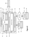
- FIG. 8 is a block diagram illustrating components, according to some example embodiments, able to read instructions from a machine-readable or computer-readable medium (e.g., a non-transitory machine-readable storage medium) and perform any one or more of the methodologies discussed herein.
- FIG. 8 shows a diagrammatic representation of hardware resources 800 including one or more processors (or processor cores) 810 , one or more memory/storage devices 820 , and one or more communication resources 830 , each of which may be communicatively coupled via a bus 840 .
- computing resource may refer to a physical or virtual device, a physical or virtual component within a computing environment, and/or a physical or virtual component within a particular device, such as computer devices, mechanical devices, memory space, processor/CPU time and/or processor/CPU usage, processor and accelerator loads, hardware time or usage, electrical power, input/output operations, ports or network sockets, channel/link allocation, throughput, memory usage, storage, network, database and applications, and/or the like.
- node virtualization e.g., NFV
- a hypervisor 802 may be executed to provide an execution environment for one or more network slices/sub-slices to utilize the hardware resources 800 .
- a “virtualized resource” may refer to compute, storage, and/or network resources provided by virtualization infrastructure to an application, device, system, etc.
- the processors 810 may include, for example, a processor 812 and a processor 814 .
- the memory/storage devices 820 may include main memory, disk storage, or any suitable combination thereof.
- the memory/storage devices 820 may include, but are not limited to, any type of volatile or nonvolatile memory such as dynamic random access memory (DRAM), static random access memory (SRAM), erasable programmable read-only memory (EPROM), electrically erasable programmable read-only memory (EEPROM), Flash memory, solid-state storage, etc.
- DRAM dynamic random access memory
- SRAM static random access memory
- EPROM erasable programmable read-only memory
- EEPROM electrically erasable programmable read-only memory
- Flash memory solid-state storage, etc.
- the communication resources 830 may include interconnection or network interface components or other suitable devices to communicate with one or more peripheral devices 804 or one or more databases 806 via a network 808 .
- the communication resources 830 may include wired communication components (e.g., for coupling via a universal serial bus (USB)), cellular communication components, NFC components, Bluetooth® components (e.g., Bluetooth® Low Energy), Wi-Fi® components, and other communication components.
- wired communication components e.g., for coupling via a universal serial bus (USB)
- cellular communication components e.g., for coupling via a universal serial bus (USB)
- NFC components e.g., NFC components
- Bluetooth® components e.g., Bluetooth® Low Energy
- Wi-Fi® components e.g., Wi-Fi® components
- the term “network resource” or “communication resource” may refer to computing resources that are accessible by computer devices via a communications network.
- system resources may refer to any kind of shared entities to provide services, and
- Instructions 850 may comprise software, a program, an application, an applet, an app, or other executable code for causing at least any of the processors 810 to perform any one or more of the methodologies discussed herein.
- the instructions 850 may reside, completely or partially, within at least one of the processors 810 (e.g., within the processor's cache memory), the memory/storage devices 820 , or any suitable combination thereof.
- any portion of the instructions 850 may be transferred to the hardware resources 800 from any combination of the peripheral devices 804 or the databases 806 .
- the memory of processors 810 , the memory/storage devices 820 , the peripheral devices 804 , and the databases 806 are examples of computer-readable and machine-readable media.
- At least one of the components set forth in one or more of the preceding figures may be configured to perform one or more operations, techniques, processes, and/or methods as set forth in the example section below.
- the baseband circuitry as described above in connection with one or more of the preceding figures may be configured to operate in accordance with one or more of the examples set forth below.
- circuitry associated with a UE, base station, network element, etc. as described above in connection with one or more of the preceding figures may be configured to operate in accordance with one or more of the examples set forth below in the example section.
- Example 1 includes a method of operating a UE, the method comprising: determining a first spatial filter for a first physical uplink channel (PUCH) transmission in a first component carrier; determining a second spatial filter for a second PUCH transmission in a second component carrier, the second spatial filter being different from the first spatial filter; determining, based on a priority rule, the first PUCH transmission has a higher priority than the second PUCH transmission; transmitting, based on said determination that the first PUCH transmission has the higher priority, the first PUCH transmission in the first component carrier with the first spatial filter; and transmitting the second PUCH in the second component carrier with the first spatial filter or dropping the second PUCH transmission.
- PUCH physical uplink channel
- Example 2 includes the method of example 1 or some other example herein, wherein the first PUCH transmission is a physical uplink control channel transmission, a physical uplink shared channel transmission, a physical random access channel transmission, or a sounding reference signal.
- the first PUCH transmission is a physical uplink control channel transmission, a physical uplink shared channel transmission, a physical random access channel transmission, or a sounding reference signal.
- Example 3 includes the method of example 1 or some other example herein, further comprising determining the first spatial filter based on a quasi-colocation assumption.
- Example 4 includes the method of example 1 or some other example herein, wherein the priority rule provides a higher priority for PUCH transmissions with earlier starting symbols and the first PUCH transmission includes a starting symbol that is earlier than a starting symbol of the second PUCH transmission.
- Example 5 includes the method of example 1 or some other example herein, wherein the priority rule provides a higher priority for PUCH transmissions with smaller serving cell indices and the first PUCH transmission includes a serving cell index that is smaller than a serving cell index of the second PUCH transmission.
- Example 6 includes a method of example 1 or some other example herein, wherein the first and second PUCH transmissions are first and second physical uplink shared channel (PUSCH) transmissions and the priority rule provides a higher priority for PUSCH transmissions that are grant-based transmissions.
- first and second PUCH transmissions are first and second physical uplink shared channel (PUSCH) transmissions and the priority rule provides a higher priority for PUSCH transmissions that are grant-based transmissions.
- PUSCH physical uplink shared channel
- Example 7 includes the method of example 6 or some other example herein, wherein grant-based transmissions are transmissions scheduled by DCI formats 0_0 or 0_1.
- Example 8 includes the method of example 1 or some other example herein, wherein the first and second PUCH transmissions are first and second physical uplink shared channel (PUSCH) transmissions, the priority rule provides a higher priority for PUSCH transmissions that are multiplexed with uplink control information, the first PUSCH transmission is multiplexed with uplink control information, and the second PUSCH transmission is not multiplexed with uplink control information.
- PUSCH physical uplink shared channel
- Example 9 includes a method of operating a UE, the method comprising: determining a first physical uplink channel (PUCH) transmission is to be transmitted in a first component carrier with a first transmit beam; determining a second PUCH transmission is to be transmitted in a second component carrier with a second transmit beam; determining, based on the priority rule, the first PUCH transmission has a higher priority than the second PUCH transmission; transmitting the first PUCH transmission with the first transmit beam; and transmitting the second PUCH transmission with the first transmit beam or drop the second PUCH transmission.
- PUCH physical uplink channel
- Example 10 includes the method of example 9 or some other example herein, wherein the first PUCH transmission is a first physical uplink shared channel (PUSCH) transmission multiplexed with first uplink control information (UCI), the second PUCH transmission is a second PUSCH transmission multiplexed with second UCI, the priority rule is to provide a priority ranking based on UCI content, and content of the first UCI having a higher priority than content of the second UCI.
- PUSCH physical uplink shared channel
- UCI uplink control information
- the priority rule is to provide a priority ranking based on UCI content, and content of the first UCI having a higher priority than content of the second UCI.
- Example 11 includes the method of example 9 or some other example herein, wherein the first PUCH transmission is a first physical uplink control channel (PUCCH) transmission having first PUCCH content, the second PUCH transmission is a second PUCCH transmission having second PUCCH content, the priority rule is to provide a priority ranking based on PUCCH content, and first PUCCH content having a higher priority than the second PUCCH content.
- PUCCH physical uplink control channel
- Example 12 includes the method of example 10 or 11 or some other example herein, wherein the priority ranking provides hybrid automatic repeat request-acknowledgment (HARQ) feedback with a higher priority than scheduling requests (SRs), SRs with higher priority than channel state information (CSI), and CSI with higher CSI priority higher priority than CSI with lower CSI priority.
- HARQ hybrid automatic repeat request-acknowledgment
- Example 13 includes the method of example 11 or some other example herein, wherein the priority rule provides a priority based on an index of a PUCCH resource identifier.
- Example 14 includes a method of example 9 or some other example herein, wherein the first PUCH transmission is a physical uplink shared channel (PUSCH) transmission, the second PUCH transmission is a physical uplink control channel PUCCH transmission, and the priority rule provides PUSCH transmissions with a higher priority than PUCCH transmissions.
- PUSCH physical uplink shared channel
- Example 15 includes the method of example 9 or some other example herein, wherein the first PUCH transmission is a physical uplink control channel (PUCCH) transmission with first PUCCH content, the second PUCH transmission is a physical uplink shared channel (PUSCH) transmission, and the priority rule provides PUCCH transmissions with the first PUCCH content with a higher priority than PUSCH transmissions.
- PUCCH physical uplink control channel
- PUSCH physical uplink shared channel
- Example 16 includes the method of example 15 or some other example herein, wherein the first PUCCH content includes hybrid automatic repeat request-acknowledgment (HARQ) information or scheduling requests (SR).
- HARQ hybrid automatic repeat request-acknowledgment
- SR scheduling requests
- Example 17 includes the method of example 9 or some other example herein, wherein the first PUCH transmission is a physical uplink control channel (PUCCH) transmission, the second PUCH transmission is a grant-based physical uplink shared channel (PUSCH) transmission, and the priority rule provides PUCCH transmissions with a higher priority than grant-based PUSCH transmissions.
- PUCCH physical uplink control channel
- PUSCH grant-based physical uplink shared channel
- Example 18 includes a method of example 9 or some other example herein, wherein the first PUCH transmission is a physical uplink shared channel (PUSCH) transmission, the second PUCH transmission is a physical uplink control channel PUCCH transmission that includes a periodic or semi-persistent channel state information (CSI) report, and the priority rule provides PUSCH transmissions with a higher priority than PUCCH transmissions that include periodic or semi-persistent CSI reports.
- PUSCH physical uplink shared channel
- CSI channel state information
- Example 19 includes the method of example 9 or some other example herein, wherein one of the first or second PUCH transmission is a physical uplink shared channel (PUSCH) transmission multiplexed with first control information, the other of the first or second PUCH transmission is a physical uplink control channel (PUCCH) having second control information, the priority rule is to provide a priority ranking based on control information, and the processing circuitry is to determine the first PUCH transmission has a higher priority than the second PUCH transmission based on relative priorities of the first and second control information.
- PUSCH physical uplink shared channel
- PUCCH physical uplink control channel
- Example 20 includes a method of example 9 or some other example herein, wherein the priority rule provides relatively priorities, in decreasing order, as: a physical random access channel transmission on a primary cell; a physical uplink control channel (PUCCH) transmission with hybrid automatic repeat request-acknowledgment (HARQ-ACK) information or scheduling request and a physical uplink shared channel (PUSCH) transmission with HARQ-ACK information; a PUCCH/PUSCH transmission with channel state information (CSI); a PUSCH transmission without HARQ-ACK or CSI; an aperiodic sounding reference signal (SRS); and a semi-persistent or periodic SRS.
- PUCCH physical uplink control channel
- HARQ-ACK hybrid automatic repeat request-acknowledgment
- PUSCH physical uplink shared channel
- CSI channel state information
- SRS aperiodic sounding reference signal
- Example 21 includes a method of operating a UE, the method comprising: determining first and second physical uplink channel (PUCH) transmissions are to be multiplexed in frequency and are to be transmitted with first and second spatial filters, respectively; determining the first PUCH transmission is a prioritized transmission and the second PUCH transmission is a de-prioritized transmission; transmitting the first PUCH transmission with the first spatial filter; and dropping the second PUCH transmission or transmitting the second PUCH transmission with the first spatial filter.
- PUCH physical uplink channel
- Example 22 includes a method of example 21 or some other example herein, wherein to determine the first PUCH transmission is a prioritized transmission and the second PUCH transmission is a de-prioritized transmission based on a priority rule.
- Example 23 includes a method of example 22 or some other example herein, wherein the priority rule is to prioritize PUCH transmissions based on type of PUCH transmission, content of PUCH transmission, or parameters associated with PUCH transmission.
- Example 24 may include an apparatus comprising means to perform one or more elements of a method described in or related to any of examples 1-23, or any other method or process described herein.
- Example 25 may include one or more non-transitory computer-readable media comprising instructions to cause an electronic device, upon execution of the instructions by one or more processors of the electronic device, to perform one or more elements of a method described in or related to any of examples 1-23, or any other method or process described herein.
- Example 26 may include an apparatus comprising logic, modules, or circuitry to perform one or more elements of a method described in or related to any of examples 1-23, or any other method or process described herein.
- Example 27 may include a method, technique, or process as described in or related to any of examples 1-23, or portions or parts thereof.
- Example 28 may include an apparatus comprising: one or more processors and one or more computer readable media comprising instructions that, when executed by the one or more processors, cause the one or more processors to perform the method, techniques, or process as described in or related to any of examples 1-23, or portions thereof.
- Example 29 may include a signal as described in or related to any of examples 1-23, or portions or parts thereof.
- Example 30 may include a signal in a wireless network as shown and described herein.
- Example 31 may include a method of communicating in a wireless network as shown and described herein.
- Example 32 may include a system for providing wireless communication as shown and described herein.
- Example 33 may include a device for providing wireless communication as shown and described herein.
Abstract
Description
Claims (20)
Priority Applications (1)
| Application Number | Priority Date | Filing Date | Title |
|---|---|---|---|
| US17/282,931 US11882556B2 (en) | 2018-10-05 | 2019-10-04 | Transmission of physical uplink channels and signals for new radio beamformed system |
Applications Claiming Priority (3)
| Application Number | Priority Date | Filing Date | Title |
|---|---|---|---|
| US201862742083P | 2018-10-05 | 2018-10-05 | |
| US17/282,931 US11882556B2 (en) | 2018-10-05 | 2019-10-04 | Transmission of physical uplink channels and signals for new radio beamformed system |
| PCT/US2019/054680 WO2020072893A1 (en) | 2018-10-05 | 2019-10-04 | Transmission of physical uplink channels and signals for new radio beamformed system |
Publications (2)
| Publication Number | Publication Date |
|---|---|
| US20210410165A1 US20210410165A1 (en) | 2021-12-30 |
| US11882556B2 true US11882556B2 (en) | 2024-01-23 |
Family
ID=70055443
Family Applications (1)
| Application Number | Title | Priority Date | Filing Date |
|---|---|---|---|
| US17/282,931 Active 2040-09-21 US11882556B2 (en) | 2018-10-05 | 2019-10-04 | Transmission of physical uplink channels and signals for new radio beamformed system |
Country Status (3)
| Country | Link |
|---|---|
| US (1) | US11882556B2 (en) |
| CN (1) | CN112805955A (en) |
| WO (1) | WO2020072893A1 (en) |
Families Citing this family (4)
| Publication number | Priority date | Publication date | Assignee | Title |
|---|---|---|---|---|
| CN116235581A (en) * | 2020-07-30 | 2023-06-06 | 高通股份有限公司 | Quasi co-location (QCL) assumption of simultaneous Physical Uplink Control Channel (PUCCH) and Physical Uplink Shared Channel (PUSCH) |
| CN114070524B (en) * | 2020-08-07 | 2023-04-28 | 维沃移动通信有限公司 | Information processing method, device and user equipment |
| US20220408425A1 (en) * | 2021-06-17 | 2022-12-22 | Samsung Electronics Co., Ltd. | User equipment including plurality of antenna panels and communication system including the same |
| US20230015378A1 (en) * | 2021-07-06 | 2023-01-19 | Qualcomm Incorporated | Techniques for selecting spatial relation information for simultaneous physical uplink control channel resources across multiple component carriers |
Citations (2)
| Publication number | Priority date | Publication date | Assignee | Title |
|---|---|---|---|---|
| WO2018143741A1 (en) | 2017-02-05 | 2018-08-09 | 엘지전자 주식회사 | Method for transmitting physical uplink shared channel in wireless communication system and device therefor |
| US20220225362A1 (en) * | 2021-01-13 | 2022-07-14 | Ofinno, Llc | PUSCH Repetition via a Plurality of TRPs |
Family Cites Families (8)
| Publication number | Priority date | Publication date | Assignee | Title |
|---|---|---|---|---|
| US8965442B2 (en) * | 2010-05-07 | 2015-02-24 | Qualcomm Incorporated | Uplink power control in aggregated carrier communication systems |
| US9930677B2 (en) * | 2010-12-07 | 2018-03-27 | Sharp Kabushiki Kaisha | Prioritizing multiple channel state information (CSI) reporting with carrier aggregation |
| KR20130077387A (en) * | 2011-12-29 | 2013-07-09 | 주식회사 팬택 | Method and apparatus of conrtolling transmission power in wireless communication system |
| US9338768B2 (en) * | 2012-07-27 | 2016-05-10 | Intel Corporation | Uplink power control for physical uplink control channel |
| US9876620B2 (en) * | 2013-01-10 | 2018-01-23 | Samsung Electronics Co., Ltd. | Uplink control information transmissions/receptions in wireless networks |
| EP3823206B1 (en) * | 2015-07-30 | 2023-05-31 | Apple Inc. | Ofdma-based multiplexing of uplink control information |
| US11153126B2 (en) * | 2016-06-22 | 2021-10-19 | Apple Inc. | Uplink sounding reference signal (SRS) transmission in carrier aggregation system |
| WO2018143731A1 (en) * | 2017-02-05 | 2018-08-09 | 엘지전자 주식회사 | Method for supporting plurality of transmission time intervals, plurality of subcarrier intervals or plurality of processing times in wireless communication system, and device therefor |
-
2019
- 2019-10-04 US US17/282,931 patent/US11882556B2/en active Active
- 2019-10-04 CN CN201980065698.6A patent/CN112805955A/en active Pending
- 2019-10-04 WO PCT/US2019/054680 patent/WO2020072893A1/en active Application Filing
Patent Citations (3)
| Publication number | Priority date | Publication date | Assignee | Title |
|---|---|---|---|---|
| WO2018143741A1 (en) | 2017-02-05 | 2018-08-09 | 엘지전자 주식회사 | Method for transmitting physical uplink shared channel in wireless communication system and device therefor |
| US20190357178A1 (en) | 2017-02-05 | 2019-11-21 | Lg Electronics Inc. | Method for transmitting physical uplink shared channel in wireless communication system and device therefor |
| US20220225362A1 (en) * | 2021-01-13 | 2022-07-14 | Ofinno, Llc | PUSCH Repetition via a Plurality of TRPs |
Non-Patent Citations (7)
| Title |
|---|
| 3GPP TS 38.213 V15.3.0, "3GPP; TSGRAN; NR; Physical layer procedures for control (Release 15)," Oct. 1, 2018. |
| 3GPP TS 38.214 V15.3.0, "3GPP; TSGRAN; NR; Physical layer procedures for data (Release 15)," Oct. 1, 2018. |
| Ericsson, "On simultaneous transmission and reception in FR2," R1-1811549, 3GPP TSG RAN WG1 Meeting #94b, Chengdu, China, Sep. 29, 2018. |
| Huawei et al., "Remaining issues on simultaneous reception or transmission over CC/BWP(s)," R1-1810102, 3GPP TSG RAN WG1 Meeting #94b, Chengdu, China, Sep. 29, 2018. |
| Intel Corporation, "Remaining details on NR PUCCH," R1-1810755, 3GPP TSG RAN WG1 Meeting #94b, Chengdu, China, Sep. 29, 2018. |
| International Search Report and Written Opinion of the International Searching Authority directed to related International Patent Application No. PCT/EP2019/054680, dated Jan. 23, 2020; 10 pages. |
| NIT Docomo, Inc., "Simultaneous Tx/Rx for physical channels," R1-1811353, 3GPP TSG RAN WG1 Meeting #94b, Chengdu, China, Sep. 29, 2018. |
Also Published As
| Publication number | Publication date |
|---|---|
| WO2020072893A1 (en) | 2020-04-09 |
| CN112805955A (en) | 2021-05-14 |
| US20210410165A1 (en) | 2021-12-30 |
Similar Documents
| Publication | Publication Date | Title |
|---|---|---|
| US11641262B2 (en) | Strategic mapping of uplink resources | |
| US11882556B2 (en) | Transmission of physical uplink channels and signals for new radio beamformed system | |
| CN112166574B (en) | Method and apparatus for multiple PCell configuration for URLLC reliability | |
| CN110546928B (en) | Method and apparatus for transmitting Uplink Control Information (UCI) | |
| US11234219B2 (en) | Discovery reference signal and control resource set multiplexing | |
| US20230198601A1 (en) | Method and device for transmitting or receiving signal on basis of space parameter in wireless communication system | |
| WO2021163990A1 (en) | Uplink transmission control method and apparatus, and device thereof | |
| US11910349B2 (en) | Physical layer signaling by devices for requesting positioning-resources | |
| WO2020201118A1 (en) | Configured uplink control information mapping | |
| US11601920B2 (en) | Methods and apparatuses for multiple transmission and reception point (multi-TRP) physical uplink control channel (PUCCH) scheme determination | |
| US20220312261A1 (en) | User Equipment (UE) Supplemental BSR for Reduced Latency in High-Propagation-Delay Networks | |
| US20220312460A1 (en) | Base Station (BS) Supplemental BSR Procedures for Reduced Latency in High-Propagation-Delay Networks | |
| WO2021168648A1 (en) | Transmit power prioritization in inter-band carrier aggregation | |
| CN116491178A (en) | Service group for random access | |
| CN115606305A (en) | Energy detection threshold for wireless communication | |
| US11910350B2 (en) | Physical layer signaling by base stations for provisioning positioning-resources | |
| US11617167B2 (en) | Enhanced traffic co-existence with multi-panel user equipment (UE) | |
| US11647465B2 (en) | Power control enhancements for physical uplink shared channel (PUSCH) multiplexing uplink control information (UCI) of different priority | |
| WO2022082805A1 (en) | Communication method and device | |
| US20230353316A1 (en) | Method and apparatus for channel state information report in wireless communication system | |
| US20230397127A1 (en) | Reporting of achievable power per component carrier with multiple power sources | |
| WO2022082542A1 (en) | Terminal capability transmission method, apparatus and system | |
| US20220322446A1 (en) | Base Station (BS) RACH Procedures for Reduced Latency in High-Propagation-Delay Networks | |
| US20220312489A1 (en) | User Equipment (UE) RACH Procedures for Reduced Latency in High-Propagation-Delay Networks | |
| JP2024500888A (en) | Enabling dynamic switching between multiple transmit/receive point physical uplink control channel method and single transmit/receive point physical uplink control channel method |
Legal Events
| Date | Code | Title | Description |
|---|---|---|---|
| FEPP | Fee payment procedure |
Free format text: ENTITY STATUS SET TO UNDISCOUNTED (ORIGINAL EVENT CODE: BIG.); ENTITY STATUS OF PATENT OWNER: LARGE ENTITY |
|
| STPP | Information on status: patent application and granting procedure in general |
Free format text: DOCKETED NEW CASE - READY FOR EXAMINATION |
|
| STPP | Information on status: patent application and granting procedure in general |
Free format text: NOTICE OF ALLOWANCE MAILED -- APPLICATION RECEIVED IN OFFICE OF PUBLICATIONS |
|
| AS | Assignment |
Owner name: APPLE INC., CALIFORNIA Free format text: ASSIGNMENT OF ASSIGNORS INTEREST;ASSIGNOR:INTEL CORPORATION;REEL/FRAME:065643/0898 Effective date: 20191130 Owner name: INTEL CORPORATION, CALIFORNIA Free format text: ASSIGNMENT OF ASSIGNORS INTEREST;ASSIGNORS:XIONG, GANG;MONDAL, BISHWARUP;ZHANG, YUSHU;AND OTHERS;SIGNING DATES FROM 20181106 TO 20181107;REEL/FRAME:065643/0848 Owner name: APPLE INC., CALIFORNIA Free format text: ASSIGNMENT OF ASSIGNORS INTEREST;ASSIGNOR:INTEL CORPORATION;REEL/FRAME:065650/0243 Effective date: 20191130 |
|
| STPP | Information on status: patent application and granting procedure in general |
Free format text: PUBLICATIONS -- ISSUE FEE PAYMENT RECEIVED |
|
| STPP | Information on status: patent application and granting procedure in general |
Free format text: PUBLICATIONS -- ISSUE FEE PAYMENT VERIFIED |
|
| STPP | Information on status: patent application and granting procedure in general |
Free format text: AWAITING TC RESP, ISSUE FEE PAYMENT VERIFIED |
|
| STPP | Information on status: patent application and granting procedure in general |
Free format text: PUBLICATIONS -- ISSUE FEE PAYMENT VERIFIED |
|
| STCF | Information on status: patent grant |
Free format text: PATENTED CASE |