US11870328B2 - Combined cooling system for motor and motor controller - Google Patents
Combined cooling system for motor and motor controller Download PDFInfo
- Publication number
- US11870328B2 US11870328B2 US17/364,364 US202117364364A US11870328B2 US 11870328 B2 US11870328 B2 US 11870328B2 US 202117364364 A US202117364364 A US 202117364364A US 11870328 B2 US11870328 B2 US 11870328B2
- Authority
- US
- United States
- Prior art keywords
- oil
- cooling
- water
- motor
- heat exchanger
- Prior art date
- Legal status (The legal status is an assumption and is not a legal conclusion. Google has not performed a legal analysis and makes no representation as to the accuracy of the status listed.)
- Active, expires
Links
Images


Classifications
-
- H—ELECTRICITY
- H02—GENERATION; CONVERSION OR DISTRIBUTION OF ELECTRIC POWER
- H02K—DYNAMO-ELECTRIC MACHINES
- H02K9/00—Arrangements for cooling or ventilating
- H02K9/19—Arrangements for cooling or ventilating for machines with closed casing and closed-circuit cooling using a liquid cooling medium, e.g. oil
- H02K9/197—Arrangements for cooling or ventilating for machines with closed casing and closed-circuit cooling using a liquid cooling medium, e.g. oil in which the rotor or stator space is fluid-tight, e.g. to provide for different cooling media for rotor and stator
-
- F—MECHANICAL ENGINEERING; LIGHTING; HEATING; WEAPONS; BLASTING
- F01—MACHINES OR ENGINES IN GENERAL; ENGINE PLANTS IN GENERAL; STEAM ENGINES
- F01P—COOLING OF MACHINES OR ENGINES IN GENERAL; COOLING OF INTERNAL-COMBUSTION ENGINES
- F01P3/00—Liquid cooling
- F01P3/12—Arrangements for cooling other engine or machine parts
-
- B—PERFORMING OPERATIONS; TRANSPORTING
- B60—VEHICLES IN GENERAL
- B60H—ARRANGEMENTS OF HEATING, COOLING, VENTILATING OR OTHER AIR-TREATING DEVICES SPECIALLY ADAPTED FOR PASSENGER OR GOODS SPACES OF VEHICLES
- B60H1/00—Heating, cooling or ventilating devices
- B60H1/00357—Air-conditioning arrangements specially adapted for particular vehicles
- B60H1/00385—Air-conditioning arrangements specially adapted for particular vehicles for vehicles having an electrical drive, e.g. hybrid or fuel cell
-
- B—PERFORMING OPERATIONS; TRANSPORTING
- B60—VEHICLES IN GENERAL
- B60H—ARRANGEMENTS OF HEATING, COOLING, VENTILATING OR OTHER AIR-TREATING DEVICES SPECIALLY ADAPTED FOR PASSENGER OR GOODS SPACES OF VEHICLES
- B60H1/00—Heating, cooling or ventilating devices
- B60H1/22—Heating, cooling or ventilating devices the heat source being other than the propulsion plant
-
- B—PERFORMING OPERATIONS; TRANSPORTING
- B60—VEHICLES IN GENERAL
- B60H—ARRANGEMENTS OF HEATING, COOLING, VENTILATING OR OTHER AIR-TREATING DEVICES SPECIALLY ADAPTED FOR PASSENGER OR GOODS SPACES OF VEHICLES
- B60H1/00—Heating, cooling or ventilating devices
- B60H1/32—Cooling devices
- B60H1/3204—Cooling devices using compression
- B60H1/3227—Cooling devices using compression characterised by the arrangement or the type of heat exchanger, e.g. condenser, evaporator
-
- B—PERFORMING OPERATIONS; TRANSPORTING
- B60—VEHICLES IN GENERAL
- B60K—ARRANGEMENT OR MOUNTING OF PROPULSION UNITS OR OF TRANSMISSIONS IN VEHICLES; ARRANGEMENT OR MOUNTING OF PLURAL DIVERSE PRIME-MOVERS IN VEHICLES; AUXILIARY DRIVES FOR VEHICLES; INSTRUMENTATION OR DASHBOARDS FOR VEHICLES; ARRANGEMENTS IN CONNECTION WITH COOLING, AIR INTAKE, GAS EXHAUST OR FUEL SUPPLY OF PROPULSION UNITS IN VEHICLES
- B60K11/00—Arrangement in connection with cooling of propulsion units
- B60K11/02—Arrangement in connection with cooling of propulsion units with liquid cooling
-
- F—MECHANICAL ENGINEERING; LIGHTING; HEATING; WEAPONS; BLASTING
- F01—MACHINES OR ENGINES IN GENERAL; ENGINE PLANTS IN GENERAL; STEAM ENGINES
- F01P—COOLING OF MACHINES OR ENGINES IN GENERAL; COOLING OF INTERNAL-COMBUSTION ENGINES
- F01P3/00—Liquid cooling
- F01P3/20—Cooling circuits not specific to a single part of engine or machine
- F01P3/207—Cooling circuits not specific to a single part of engine or machine liquid-to-liquid heat-exchanging relative to marine vessels
-
- H—ELECTRICITY
- H02—GENERATION; CONVERSION OR DISTRIBUTION OF ELECTRIC POWER
- H02K—DYNAMO-ELECTRIC MACHINES
- H02K11/00—Structural association of dynamo-electric machines with electric components or with devices for shielding, monitoring or protection
- H02K11/30—Structural association with control circuits or drive circuits
-
- H—ELECTRICITY
- H02—GENERATION; CONVERSION OR DISTRIBUTION OF ELECTRIC POWER
- H02K—DYNAMO-ELECTRIC MACHINES
- H02K9/00—Arrangements for cooling or ventilating
-
- H—ELECTRICITY
- H02—GENERATION; CONVERSION OR DISTRIBUTION OF ELECTRIC POWER
- H02K—DYNAMO-ELECTRIC MACHINES
- H02K9/00—Arrangements for cooling or ventilating
- H02K9/19—Arrangements for cooling or ventilating for machines with closed casing and closed-circuit cooling using a liquid cooling medium, e.g. oil
- H02K9/20—Arrangements for cooling or ventilating for machines with closed casing and closed-circuit cooling using a liquid cooling medium, e.g. oil wherein the cooling medium vaporises within the machine casing
-
- B—PERFORMING OPERATIONS; TRANSPORTING
- B60—VEHICLES IN GENERAL
- B60K—ARRANGEMENT OR MOUNTING OF PROPULSION UNITS OR OF TRANSMISSIONS IN VEHICLES; ARRANGEMENT OR MOUNTING OF PLURAL DIVERSE PRIME-MOVERS IN VEHICLES; AUXILIARY DRIVES FOR VEHICLES; INSTRUMENTATION OR DASHBOARDS FOR VEHICLES; ARRANGEMENTS IN CONNECTION WITH COOLING, AIR INTAKE, GAS EXHAUST OR FUEL SUPPLY OF PROPULSION UNITS IN VEHICLES
- B60K1/00—Arrangement or mounting of electrical propulsion units
- B60K2001/003—Arrangement or mounting of electrical propulsion units with means for cooling the electrical propulsion units
- B60K2001/006—Arrangement or mounting of electrical propulsion units with means for cooling the electrical propulsion units the electric motors
-
- F—MECHANICAL ENGINEERING; LIGHTING; HEATING; WEAPONS; BLASTING
- F01—MACHINES OR ENGINES IN GENERAL; ENGINE PLANTS IN GENERAL; STEAM ENGINES
- F01P—COOLING OF MACHINES OR ENGINES IN GENERAL; COOLING OF INTERNAL-COMBUSTION ENGINES
- F01P3/00—Liquid cooling
- F01P2003/008—Liquid cooling the liquid being water and oil
-
- F—MECHANICAL ENGINEERING; LIGHTING; HEATING; WEAPONS; BLASTING
- F01—MACHINES OR ENGINES IN GENERAL; ENGINE PLANTS IN GENERAL; STEAM ENGINES
- F01P—COOLING OF MACHINES OR ENGINES IN GENERAL; COOLING OF INTERNAL-COMBUSTION ENGINES
- F01P2060/00—Cooling circuits using auxiliaries
- F01P2060/04—Lubricant cooler
Definitions
- the present disclosure belongs to the technical field of motors, and particularly relates to a combined cooling system for a motor and a motor controller.
- the drive motors of existing new energy vehicles often only use an independent water cooling system or an independent oil cooling system. As the power density of the drive motor increases, a more effective cooling system is required to ensure the continuous high power and high torque output of the motor.
- the water cooling of motor uses heat conduction.
- the heat generated by the motor windings and bearings is first transferred to the motor housing provided with cooling water pipes therein, a part of the heat is taken away by the coolant, and then the radiator cools the water.
- the oil cooling of motor directly transports the cooling oil to the heated part by spraying, which can quickly and accurately take away the heat, and then the heat exchanger cools the oil.
- the present disclosure discloses a combined cooling system for a motor and a motor controller to overcome the above problems or at least partially solve the above problems.
- a combined cooling system for a motor and a motor controller wherein the cooling system comprises a water cooling assembly, an oil cooling assembly, and an oil-water heat exchanger; one end of the water cooling assembly is connected to an cooling water outlet of the motor, the other end of the water cooling assembly is only connected to an cooling water inlet of the motor controller, an cooling water outlet of the motor controller is connected to a water inlet of an oil-water heat exchanger, and a water outlet of the oil-water heat exchanger is connected to a cooling water inlet of the motor; or, the other end of the water cooling assembly is connected to the cooling water inlet of the motor controller and the water inlet of the oil-water heat exchanger respectively, and the cooling water outlet of the motor controller and the water outlet of the oil-water heat exchanger are respectively connected to the cooling water inlet of the motor; or, the other end of the water cooling assembly is connected to the cooling water inlet of the motor controller and the water inlet of the oil-water heat exchanger respectively, and the cooling water outlet of the motor controller and the water outlet of the oil
- one end of the oil cooling assembly is connected to a cooling oil outlet of the motor, the other end of the oil cooling assembly is connected to an oil inlet of the oil-water heat exchanger, and an oil outlet of the oil-water heat exchanger is connected to a cooling oil inlet of the motor.
- the water cooling assembly comprises a radiator, a fan, a first water pump, and a water pipe, the radiator is connected in series with the first water pump, and the fan is used for cooling the radiator;
- the oil cooling assembly comprises an oil pump and an oil pipe, and the oil pump is connected in series between the cooling oil outlet of the motor and the oil inlet of the oil-water heat exchanger via the oil pipe.
- the first water pump may also be connected in series between the cooling water outlet of the motor controller and the water inlet of the oil-water heat exchanger via the water pipe; or, the first water pump may also be connected in series between the water outlet of the oil-water heat exchanger and the cooling water inlet of the motor via the water pipe.
- the water cooling assembly comprises a radiator, a fan, a second water pump, a third water pump and a water pipe, the second water pump and the third water pump are connected in parallel and then are connected in series to the radiator, the water outlet of the second water pump is connected to the cooling water inlet of the motor controller, and the cooling water outlet of the motor controller is connected to the cooling water inlet of the motor;
- a water outlet of the third water pump is connected to a water inlet of the oil-water heat exchanger, and a water outlet of the oil-water heat exchanger is connected to the cooling water inlet of the motor.
- the oil pump may also be connected in series between the oil outlet of the oil-water heat exchanger and the cooling oil inlet of the motor.
- the oil cooling assembly is further provided with an oil cooling radiator and an oil cooling fan, and the oil cooling radiator and the oil cooling fan may be provided separately, or shared with the radiator and the fan in the water cooling assembly.
- the motor controller, the water cooling assembly and the oil cooling assembly are controlled by a controller.
- the controller is a vehicle controller or a cooling system controller.
- the cooling system further comprises an air-conditioning cooling assembly
- the air-conditioning cooling assembly comprises an air-conditioning pipeline and a condenser
- the condenser is arranged on the oil-water heat exchanger to reduce a temperature of a fluid in the oil-water heat exchanger.
- the air-conditioning cooling assembly is controlled by a vehicle controller or a cooling system controller.
- the technical solution disclosed by the present disclosure utilizes the characteristic that the operating temperature of the motor controller is lower than the operating temperature of the motor, and disposes the motor controller closer to the water cooling assembly to meet the requirements of normal operation of the motor. Moreover, through the cooperation in the combined cooling system, the consumption of electric energy can be reduced, the cooling effect of the motor can also be improved, and the environmental adaptability of the motor can be effectively enhanced.
- the present disclosure realizes the linked and intelligent control of the water pump, oil pump and fan in the combined cooling system, obtains the greatest comprehensive benefit, and improves the balance of energy saving and cooling performance of the combined cooling system.
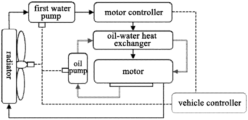
- FIG. 1 is a schematic diagram of the structure of a combined cooling system according to an embodiment of the present disclosure
- FIG. 2 is a schematic diagram of a different control structure of the embodiment of FIG. 1 ;
- FIG. 3 is a schematic diagram of the structure of a different water pump connection relationship of the embodiment of FIG. 1 ;
- FIG. 4 is a schematic diagram of the structure of a combined cooling system according to another embodiment of the present disclosure.
- FIG. 5 is a schematic diagram of the structure of a combined cooling system according to yet another embodiment of the present disclosure.
- the double solid line represents the cooling oil circuit
- the single solid line represents the cooling water circuit
- the dashed line represents the control circuit
- the thick solid line represents the air conditioning pipeline
- the motor controller is an integrated circuit that controls the motor to work in accordance with the set direction, speed, angle, and response time through active work.
- the function of the motor controller is to, according to instructions such as gear position, throttle position and brake, convert the electric energy stored in the power battery into the electric energy required to drive the motor, control the driving conditions such as start-up, advance and retreat speed, and climbing ability of the electric vehicle, or help the electric vehicle to brake and store part of the braking energy in the power battery.
- the operating temperature of the motor controller is lower than the operating temperature of the motor.
- the motor controller works at about 90 degrees Celsius, while the motor body can withstand a high temperature of more than 100 degrees Celsius.
- an effective combined cooling system for cooling the motor is designed, which can effectively improve the cooling efficiency of the motor and obtain the maximum benefit of energy consumption and cooling efficiency.
- the combined cooling system comprises a water cooling assembly, an oil cooling assembly, and an oil-water heat exchanger.
- the water cooling assembly comprises a radiator, a fan, a plurality of water pumps, and a water pipe.
- the radiator is connected in series with the water pumps, and the plurality of water pumps are connected in parallel.
- the fan is used to cool the radiator.
- the oil cooling assembly comprises an oil pump and an oil pipe.
- the oil pump is connected in series between the cooling oil outlet of the motor and the oil inlet of the oil-water heat exchanger via the oil pipe.
- Combination 1 as shown in FIG. 1 , there is only one water pump in the water cooling assembly, namely the first water pump. At this point, one end of the water cooling assembly is connected to an cooling water outlet of the motor, the other end of the water cooling assembly is only connected to an cooling water inlet of the motor controller, an cooling water outlet of the motor controller is connected to a water inlet of an oil-water heat exchanger, and a water outlet of the oil-water heat exchanger is connected to a cooling water inlet of the motor.
- one end of the oil cooling assembly is connected to a cooling oil outlet of the motor, the other end of the oil cooling assembly is connected to an oil inlet of the oil-water heat exchanger, and an oil outlet of the oil-water heat exchanger is connected to a cooling oil inlet of the motor.
- the cooling water in the water cooling assembly is used to cool the oil in the cooling oil circuit, and the cooling source includes only a fan and a radiator.
- a fan and a radiator may also be added in the oil cooling assembly as cooling sources.
- Combination 2 as shown in FIG. 3 , one end of the water cooling assembly is connected to the cooling water outlet of the motor, the other end of the water cooling assembly is connected to the cooling water inlet of the motor controller and the water inlet of the oil-water heat exchanger respectively, and then the cooling water outlet of the motor controller and the water outlet of the oil-water heat exchanger are respectively connected to the water inlet of the radiator of the water cooling assembly and the cooling water inlet of the motor.
- the cooling water passing through the oil-water heat exchanger does not pass through the motor controller, the effect of heat exchange is better, and it is more conducive to reducing the temperature of the oil in the oil-water heat exchanger.
- the water cooling assembly comprises two water pumps: a second water pump and a third water pump.
- the second water pump is connected to the motor controller for cooling the motor controller.
- the water outlet of the third water pump is connected to the water inlet of the oil-water heat exchanger, and the water outlet of the oil-water heat exchanger is connected to the cooling water inlet of the motor, so as to cool the high-temperature oil in the cooling oil circuit.
- one end of the oil cooling assembly is connected to a cooling oil outlet of the motor, the other end of the oil cooling assembly is connected to an oil inlet of the oil-water heat exchanger, and an oil outlet of the oil-water heat exchanger is connected to a cooling oil inlet of the motor.
- the cooling water outlet of the motor controller and the water outlet of the oil-water heat exchanger are respectively connected to the water inlet of the radiator of the water cooling assembly and the cooling water inlet of the motor, thereby separately cooling the motor controller and the motor by dividing the cooling water from the radiator (i.e., the water cooling assembly), which improves the cooling efficiency of the combined cooling system and obtains a better cooling effect.
- the condenser in the air-conditioning assembly is introduced to cool the oil-water heat exchanger.
- the air-conditioning cooling assembly comprises an air-conditioning pipeline and the condenser.
- the condenser is arranged on the oil-water heat exchanger, and is used to reduce the temperature of the fluid in the oil-water heat exchanger.
- the condenser can only cool the oil circuit, and the circulation in the water cooling assembly may no longer be introduced into the oil-water heat exchanger. Of course, the water in the cooling water circuit may still be introduced into the oil-water heat exchanger.
- the embodiments of the combined cooling system of the present disclosure are not limited to these. If needed, the water circuit connection can be adjusted as shown in FIG. 3 , or the quantity of water pumps can be adjusted as shown in FIG. 4 , and all other embodiments that can improve the combined cooling efficiency of the motor are within the protection scope of the disclosure.
- the first water pump when the other end of the water cooling assembly is only connected to the cooling water inlet of the motor controller, the first water pump may also be connected in series between the cooling water outlet of the motor controller and the water inlets of the oil-water heat exchanger via a water pipe; or, the first water pump may also be connected in series between the water outlet of the oil-water heat exchanger and the cooling water inlet of the motor via a water pipe.
- the first water pump may be arranged at any place in the cooling water circuit, so as to realize the cooling water circulation in the water circuit.
- the oil pump may also be connected in series between the oil outlet of the oil-water heat exchanger and the cooling oil inlet of the motor.
- the oil pump may be arranged at any place in the cooling oil circuit to realize the cooling oil circulation in oil circuit.
- an oil cooling radiator and an oil cooling fan are also provided in the oil cooling assembly, and the oil cooling radiator and the oil cooling fan may be provided separately, or share with the radiator and the fan in the water cooling assembly, thereby enhancing the cooling effect.
- the motor controller, the water pump and fan in the water cooling assembly, and the oil pump in the oil cooling assembly may be controlled by the controller. According to the load and working conditions, the flow rate of the water pump and the oil pump can be adjusted, and the water pump and the oil pump can be started or stopped, the wind speed of the fan can be controlled, and the fan can be started or stopped.
- the controller may be a cooling system controller or a vehicle controller.
- the water cooling assembly and the oil cooling assembly are controlled by a special cooling system controller, and the cooling system controller is further controlled by a vehicle controller. Control instructions are transferred between the cooling system controller and the vehicle controller.
- the air-conditioning cooling assembly may be controlled by a cooling system controller or directly controlled by a vehicle controller.
- the embodiments of the present disclosure disclose a variety of structures of combined cooling system of motor. They have an independent water cooling system, which can effectively ensure a stable and continuous power output of the motor. They have an independent oil cooling system, which can effectively increase the power density of the motor.
- the two systems can be used in combination. Different strategies are adopted under different working conditions.
- the combined control of the two systems is achieved by controlling the cooling fan, water pump, and oil pump. When the natural environment temperature is high and the vehicle is under high load, the two systems can be operated at full load.
- the above system can effectively improve the motor power, torque density, and effectively improve the environmental adaptability of motor.
Landscapes
- Engineering & Computer Science (AREA)
- Mechanical Engineering (AREA)
- Power Engineering (AREA)
- Combustion & Propulsion (AREA)
- Chemical & Material Sciences (AREA)
- Physics & Mathematics (AREA)
- Thermal Sciences (AREA)
- Transportation (AREA)
- General Engineering & Computer Science (AREA)
- Life Sciences & Earth Sciences (AREA)
- Sustainable Development (AREA)
- Sustainable Energy (AREA)
- Ocean & Marine Engineering (AREA)
- Motor Or Generator Cooling System (AREA)
Abstract
Description
Claims (3)
Applications Claiming Priority (2)
| Application Number | Priority Date | Filing Date | Title |
|---|---|---|---|
| CN202022307041.9 | 2020-10-16 | ||
| CN202022307041.9U CN213892157U (en) | 2020-10-16 | 2020-10-16 | Motor and motor controller combined cooling system |
Publications (2)
| Publication Number | Publication Date |
|---|---|
| US20220123629A1 US20220123629A1 (en) | 2022-04-21 |
| US11870328B2 true US11870328B2 (en) | 2024-01-09 |
Family
ID=77113477
Family Applications (1)
| Application Number | Title | Priority Date | Filing Date |
|---|---|---|---|
| US17/364,364 Active 2041-10-29 US11870328B2 (en) | 2020-10-16 | 2021-06-30 | Combined cooling system for motor and motor controller |
Country Status (3)
| Country | Link |
|---|---|
| US (1) | US11870328B2 (en) |
| EP (1) | EP3984798B1 (en) |
| CN (1) | CN213892157U (en) |
Families Citing this family (6)
| Publication number | Priority date | Publication date | Assignee | Title |
|---|---|---|---|---|
| CN114244032A (en) * | 2021-12-28 | 2022-03-25 | 擎风电驱动科技(苏州)有限公司 | Integrated oil-cooled motor assembly for electric motorcycle |
| DE102022204999A1 (en) * | 2022-05-19 | 2023-11-23 | Vitesco Technologies GmbH | Method for operating a coolant circuit, computer program, computer program product, heat transport system and vehicle |
| CN114857250B (en) * | 2022-05-30 | 2026-01-02 | 中国第一汽车股份有限公司 | A cooling system, control method and electric vehicle for an electric vehicle |
| US12208671B2 (en) * | 2022-09-28 | 2025-01-28 | Dana Automotive Systems Group, Llc | Method and systems for powertrain |
| DE102022212045A1 (en) * | 2022-11-14 | 2024-05-16 | Robert Bosch Gesellschaft mit beschränkter Haftung | Pre-integrated oil cooling module and vehicle |
| FR3159987B1 (en) * | 2024-03-11 | 2026-01-30 | Stellantis Auto Sas | CONTROL OF THE COOLING OF THE LUBRICATING OIL OF AN ELECTRIC VEHICLE'S POWERTRAIN |
Citations (4)
| Publication number | Priority date | Publication date | Assignee | Title |
|---|---|---|---|---|
| DE102011117102A1 (en) | 2011-10-27 | 2012-05-31 | Daimler Ag | Circuit arrangement for cooling e.g. electrical motor in diesel engine of hybrid vehicle, has low-temperature circuit opening at outlet of cylinder head or into high-temperature circuit in flow direction |
| US10287964B2 (en) * | 2015-12-21 | 2019-05-14 | Toyota Jidosha Kabushiki Kaisha | Vehicular cooling system |
| EP3517335A1 (en) | 2018-01-25 | 2019-07-31 | Toyota Jidosha Kabushiki Kaisha | Electric vehicle |
| CN111313611A (en) | 2018-12-12 | 2020-06-19 | 晟昌机电股份有限公司 | Motor cooling structure |
-
2020
- 2020-10-16 CN CN202022307041.9U patent/CN213892157U/en active Active
-
2021
- 2021-06-30 US US17/364,364 patent/US11870328B2/en active Active
- 2021-10-12 EP EP21202281.8A patent/EP3984798B1/en active Active
Patent Citations (5)
| Publication number | Priority date | Publication date | Assignee | Title |
|---|---|---|---|---|
| DE102011117102A1 (en) | 2011-10-27 | 2012-05-31 | Daimler Ag | Circuit arrangement for cooling e.g. electrical motor in diesel engine of hybrid vehicle, has low-temperature circuit opening at outlet of cylinder head or into high-temperature circuit in flow direction |
| US10287964B2 (en) * | 2015-12-21 | 2019-05-14 | Toyota Jidosha Kabushiki Kaisha | Vehicular cooling system |
| EP3517335A1 (en) | 2018-01-25 | 2019-07-31 | Toyota Jidosha Kabushiki Kaisha | Electric vehicle |
| US10960752B2 (en) * | 2018-01-25 | 2021-03-30 | Toyota Jidosha Kabushiki Kaisha | Electric vehicle |
| CN111313611A (en) | 2018-12-12 | 2020-06-19 | 晟昌机电股份有限公司 | Motor cooling structure |
Non-Patent Citations (1)
| Title |
|---|
| European Search Report which issued in connection with a corresponding foreign application dated Apr. 7, 2022. |
Also Published As
| Publication number | Publication date |
|---|---|
| EP3984798A2 (en) | 2022-04-20 |
| CN213892157U (en) | 2021-08-06 |
| EP3984798A3 (en) | 2022-05-04 |
| US20220123629A1 (en) | 2022-04-21 |
| EP3984798B1 (en) | 2023-11-29 |
Similar Documents
| Publication | Publication Date | Title |
|---|---|---|
| US11870328B2 (en) | Combined cooling system for motor and motor controller | |
| CN101109310A (en) | Intelligentized heat management system of propulsion plant | |
| CN112339614A (en) | A collaborative management method suitable for fuel cell vehicle thermal system | |
| CN115556566A (en) | Thermal management system and crane for pure electric crawler crane | |
| CN116278586A (en) | Fuel cell vehicle thermal management system and method | |
| CN114885569A (en) | Cooling system | |
| CN113147366A (en) | Cooling system of plateau type hybrid vehicle | |
| CN114094137B (en) | Thermal management system of vehicle and vehicle | |
| CN115923442A (en) | Extended range electric vehicle thermal management system | |
| CN212289436U (en) | Thermal management system and electric automobile | |
| CN212671925U (en) | High-efficient thoughtlessly moves engine cooling system | |
| CN212671923U (en) | High-efficient thoughtlessly moves engine cooling system | |
| CN212171867U (en) | New energy automobile integrated form heat management unit | |
| CN113309764A (en) | Pure electric engineering machinery heat dissipation system and control method | |
| CN219076949U (en) | Range-extending type electric automobile thermal management system | |
| CN111180830A (en) | Battery Motor Integrated Thermal Management System for Pure Electric or Hybrid Electric Vehicles | |
| CN118024857A (en) | New energy engineering vehicle and thermal management system thereof | |
| CN215370434U (en) | Pure electric engineering machinery cooling system | |
| CN223414104U (en) | Fuel cell thermal management system, fuel cell and fuel cell vehicle | |
| CN213688006U (en) | Cooling system | |
| CN112078435B (en) | A fuel cell vehicle cooling system | |
| CN116587804A (en) | A hydrogen fuel cell vehicle dual coolant integrated thermal management system and method | |
| CN210390731U (en) | Whole car cooling system of electric automobile | |
| CN223803411U (en) | A liquid-cooled temperature control system for electric trucks | |
| CN115163280A (en) | Cooling system suitable for agricultural machine and harvester |
Legal Events
| Date | Code | Title | Description |
|---|---|---|---|
| AS | Assignment |
Owner name: JING-JIN ELECTRIC TECHNOLOGIES CO., LTD., CHINA Free format text: ASSIGNMENT OF ASSIGNORS INTEREST;ASSIGNORS:SHAO, KUIZHU;ZHANG, ZHICHAO;DUAN, YU;AND OTHERS;REEL/FRAME:056724/0257 Effective date: 20210625 |
|
| FEPP | Fee payment procedure |
Free format text: ENTITY STATUS SET TO UNDISCOUNTED (ORIGINAL EVENT CODE: BIG.); ENTITY STATUS OF PATENT OWNER: LARGE ENTITY |
|
| STPP | Information on status: patent application and granting procedure in general |
Free format text: DOCKETED NEW CASE - READY FOR EXAMINATION |
|
| STPP | Information on status: patent application and granting procedure in general |
Free format text: RESPONSE TO NON-FINAL OFFICE ACTION ENTERED AND FORWARDED TO EXAMINER |
|
| STPP | Information on status: patent application and granting procedure in general |
Free format text: NON FINAL ACTION MAILED |
|
| STPP | Information on status: patent application and granting procedure in general |
Free format text: RESPONSE TO NON-FINAL OFFICE ACTION ENTERED AND FORWARDED TO EXAMINER |
|
| STPP | Information on status: patent application and granting procedure in general |
Free format text: NOTICE OF ALLOWANCE MAILED -- APPLICATION RECEIVED IN OFFICE OF PUBLICATIONS |
|
| STPP | Information on status: patent application and granting procedure in general |
Free format text: AWAITING TC RESP., ISSUE FEE NOT PAID |
|
| STPP | Information on status: patent application and granting procedure in general |
Free format text: NOTICE OF ALLOWANCE MAILED -- APPLICATION RECEIVED IN OFFICE OF PUBLICATIONS |
|
| STPP | Information on status: patent application and granting procedure in general |
Free format text: PUBLICATIONS -- ISSUE FEE PAYMENT VERIFIED |
|
| STPP | Information on status: patent application and granting procedure in general |
Free format text: AWAITING TC RESP, ISSUE FEE PAYMENT VERIFIED |
|
| STPP | Information on status: patent application and granting procedure in general |
Free format text: PUBLICATIONS -- ISSUE FEE PAYMENT VERIFIED |
|
| STCF | Information on status: patent grant |
Free format text: PATENTED CASE |