US11867500B2 - Time-of-flight (TOF) assisted structured light imaging - Google Patents
Time-of-flight (TOF) assisted structured light imaging Download PDFInfo
- Publication number
- US11867500B2 US11867500B2 US16/920,832 US202016920832A US11867500B2 US 11867500 B2 US11867500 B2 US 11867500B2 US 202016920832 A US202016920832 A US 202016920832A US 11867500 B2 US11867500 B2 US 11867500B2
- Authority
- US
- United States
- Prior art keywords
- tof
- location
- projector
- structured light
- image
- Prior art date
- Legal status (The legal status is an assumption and is not a legal conclusion. Google has not performed a legal analysis and makes no representation as to the accuracy of the status listed.)
- Active, expires
Links
- 238000003384 imaging method Methods 0.000 title claims abstract description 48
- 238000000034 method Methods 0.000 claims abstract description 52
- 239000011159 matrix material Substances 0.000 claims description 18
- 238000013507 mapping Methods 0.000 claims description 10
- 238000002366 time-of-flight method Methods 0.000 description 10
- 238000004458 analytical method Methods 0.000 description 7
- 230000008901 benefit Effects 0.000 description 7
- 238000005286 illumination Methods 0.000 description 7
- 230000000295 complement effect Effects 0.000 description 6
- 238000010586 diagram Methods 0.000 description 5
- 238000002474 experimental method Methods 0.000 description 3
- 238000012545 processing Methods 0.000 description 3
- 238000013459 approach Methods 0.000 description 2
- 238000004364 calculation method Methods 0.000 description 2
- 230000000694 effects Effects 0.000 description 2
- 238000005516 engineering process Methods 0.000 description 2
- 230000004927 fusion Effects 0.000 description 2
- 239000004973 liquid crystal related substance Substances 0.000 description 2
- 238000005259 measurement Methods 0.000 description 2
- 230000003287 optical effect Effects 0.000 description 2
- 238000003909 pattern recognition Methods 0.000 description 2
- 238000011160 research Methods 0.000 description 2
- 238000013473 artificial intelligence Methods 0.000 description 1
- 230000003190 augmentative effect Effects 0.000 description 1
- 230000005540 biological transmission Effects 0.000 description 1
- 238000004590 computer program Methods 0.000 description 1
- 238000013461 design Methods 0.000 description 1
- 239000012634 fragment Substances 0.000 description 1
- 239000000463 material Substances 0.000 description 1
- 238000012986 modification Methods 0.000 description 1
- 230000004048 modification Effects 0.000 description 1
- 239000005022 packaging material Substances 0.000 description 1
- 230000000737 periodic effect Effects 0.000 description 1
- 238000012805 post-processing Methods 0.000 description 1
- 229910052710 silicon Inorganic materials 0.000 description 1
- 239000010703 silicon Substances 0.000 description 1
- 230000003068 static effect Effects 0.000 description 1
- 230000002123 temporal effect Effects 0.000 description 1
- 238000012360 testing method Methods 0.000 description 1
- 238000013519 translation Methods 0.000 description 1
Images


Classifications
-
- G—PHYSICS
- G01—MEASURING; TESTING
- G01B—MEASURING LENGTH, THICKNESS OR SIMILAR LINEAR DIMENSIONS; MEASURING ANGLES; MEASURING AREAS; MEASURING IRREGULARITIES OF SURFACES OR CONTOURS
- G01B11/00—Measuring arrangements characterised by the use of optical techniques
- G01B11/24—Measuring arrangements characterised by the use of optical techniques for measuring contours or curvatures
- G01B11/25—Measuring arrangements characterised by the use of optical techniques for measuring contours or curvatures by projecting a pattern, e.g. one or more lines, moiré fringes on the object
- G01B11/2518—Projection by scanning of the object
- G01B11/2527—Projection by scanning of the object with phase change by in-plane movement of the patern
-
- G—PHYSICS
- G01—MEASURING; TESTING
- G01S—RADIO DIRECTION-FINDING; RADIO NAVIGATION; DETERMINING DISTANCE OR VELOCITY BY USE OF RADIO WAVES; LOCATING OR PRESENCE-DETECTING BY USE OF THE REFLECTION OR RERADIATION OF RADIO WAVES; ANALOGOUS ARRANGEMENTS USING OTHER WAVES
- G01S17/00—Systems using the reflection or reradiation of electromagnetic waves other than radio waves, e.g. lidar systems
- G01S17/02—Systems using the reflection of electromagnetic waves other than radio waves
- G01S17/06—Systems determining position data of a target
- G01S17/46—Indirect determination of position data
-
- G—PHYSICS
- G01—MEASURING; TESTING
- G01S—RADIO DIRECTION-FINDING; RADIO NAVIGATION; DETERMINING DISTANCE OR VELOCITY BY USE OF RADIO WAVES; LOCATING OR PRESENCE-DETECTING BY USE OF THE REFLECTION OR RERADIATION OF RADIO WAVES; ANALOGOUS ARRANGEMENTS USING OTHER WAVES
- G01S17/00—Systems using the reflection or reradiation of electromagnetic waves other than radio waves, e.g. lidar systems
- G01S17/88—Lidar systems specially adapted for specific applications
- G01S17/89—Lidar systems specially adapted for specific applications for mapping or imaging
- G01S17/894—3D imaging with simultaneous measurement of time-of-flight at a 2D array of receiver pixels, e.g. time-of-flight cameras or flash lidar
Definitions
- Embodiments of the present invention generally relate to time-of-flight assisted structured light imaging.
- Time-of-flight (TOF) depth sensors are widely used in commercial applications due to their ability to reconstruct dynamic scenes in real-time.
- TOF sensors work by illuminating the scene with an infrared (IR) light-emitting diode (LED) that is modulated by a continuous, periodic signal.
- Imaging hardware in the sensor provides pixel-level phase estimation of the reflected and scattered illumination in real-time.
- the depth measurements from these sensors tend to have inherent structural noise that may not be eliminated using image processing techniques.
- phase shifting structured light imaging the higher accuracy in dynamic scenes is achieved by capturing multiple images of a phase shifted projected pattern.
- structured light imaging produces much more accurate depth maps, such systems are typically not suitable for real-time depth imaging due to the multiple image capture.
- Embodiments of the present invention relate to methods, apparatus, and computer readable media for time-of-flight assisted structured light imaging.
- a method for computing a depth map of a scene in a structured light imaging system including a time-of-flight (TOF) sensor and a projector includes capturing a plurality of high frequency phase-shifted structured light images of the scene using a camera in the structured light imaging system, generating, concurrently with the capturing of the plurality of high frequency phase-shifted structured light images, a time-of-flight (TOF) depth image of the scene using the TOF sensor, and computing the depth map from the plurality of high frequency phase-shifted structured light images wherein the TOF depth image is used for phase unwrapping.
- TOF time-of-flight
- a structured light imaging system includes a projector and a time-of-flight (TOF) sensor, wherein the structured light imaging system is configured to compute a depth map of a scene by performing a method that includes capturing a plurality of high frequency phase-shifted structured light images of the scene using a camera in the structured light imaging system, generating, concurrently with the capturing of the plurality of high frequency phase-shifted structured light images, a time-of-flight (TOF) depth image of the scene using the TOF sensor, and computing the depth map from the plurality of high frequency phase-shifted structured light images wherein the TOF depth image is used for phase unwrapping.
- TOF time-of-flight
- a non-transitory computer readable medium storing software instructions.
- the software instructions when executed by at least one processor in a structured light imaging system including a time-of-flight (TOF) sensor and a projector, cause execution of a method for computing a depth map of a scene that includes capturing a plurality of high frequency phase-shifted structured light images of the scene using a camera in the structured light imaging system, generating, concurrently with the capturing of the plurality of high frequency phase-shifted structured light images, a time-of-flight (TOF) depth image of the scene using the TOF sensor, and computing the depth map from the plurality of high frequency phase-shifted structured light images wherein the TOF depth image is used for phase unwrapping.
- TOF time-of-flight
- FIGS. 1 A- 1 F are examples illustrating complementary errors in a triangulation-based depth system and a time-of-flight (TOF) depth system;
- FIG. 2 shows an example trinocular system configured to perform TOF assisted structured light imaging
- FIG. 3 is an example
- FIGS. 4 and 5 are flow diagrams of methods
- FIGS. 6 A- 6 F, 7 A- 7 F, 8 A, 8 B, 9 A- 9 D, and 10 A- 10 D are examples;
- FIG. 11 shows an example TOF-structured light depth sensor configured to perform TOF assisted structured light imaging
- FIGS. 12 A and 12 B are examples.
- Embodiments of the invention provide for time-of-flight (TOF) assisted structured light imaging. Further, embodiments combine the real time depth capture capability of a TOF sensor with the high accuracy of phase shifting structured light systems such that obtaining high-precision depth maps in real time is possible.
- a trinocular system includes a projector and camera for phase shifting structured light imaging and a TOF sensor for capturing a TOF depth image.
- a novel depth sensor is provided that provides the TOF assisted structured light imaging without the need for a separate camera to capture the pattern images.
- the depth sensor includes a TOF sensor and a projector. The projector projects the phase shifted structured light patterns and the imager (camera) of the TOF sensor is used to capture the pattern images.
- FIGS. 1 A- 1 F are examples illustrating this advantage.
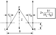
- FIG. 1 shows a ray diagram for a triangulation-based system.
- FIG. 1 D shows a ray diagram for a general TOF system with an emitter LED and a sensor Cam.
- the emitter LED and the sensor Cam are co-located as close to each other as possible. This would be a special case of the ray diagram in which LED and Cam correspond to the same location in space.
- the distance Z tof is estimated by the TOF sensor by calculating the phase difference ⁇ between the emitter LED and the receiving sensor Cam. The relationship between the two is given by
- FIG. 1 E The consequence of measuring a light path (as opposed to a single ray) assuming no multi-path effects such as inter-reflections or subsurface scattering is shown in FIG. 1 E .
- the location of the point P given the path Z tof traveled by light from the emitter LED to the receiving sensor Cam can be anywhere on an ellipse. This directly follows from the definition of an ellipse as the locus of points whose sum of distances to two foci is a constant value. As shown in FIG. 1 , the foci are the emitter LED and the sensor Cam while the constant sum is the light path Z tof .
- this ellipsoid ambiguity is broken by the ray geometry of the sensor Cam, which is usually assumed to be a pinhole camera, and whose viewing ray for P intersects the ellipse in only one location (since the ray begins inside the ellipse) as shown in FIG. 1 E . Therefore, unlike pure triangulation, the TOF sensor is designed to use a form of trilateration.
- errors may occur in the estimated depth due to an error in the phase ⁇ .
- the phase error ⁇ is illustrated geometrically in FIG. 1 F as errors e a and e b in the paths a and b traversed by the light from the emitter LED.
- there may be errors in the projected ray from the sensor Cam which is represented as a location error e cam . This error may result, for example, from low resolution in the sensor Cam or rotation or translation errors in its relative position with respect to the emitter LED.
- the estimated depth error due to an error in the phase ⁇ may be described by taking the derivative of Eq. 3,
- the error ⁇ in the estimated phase difference ⁇ increases the width of the ellipse where the point P could lie.
- the entire ellipse is not being considered, just the region that lies within the viewing frustrum of the receiver Cam.
- This ellipsoidal fragment is shown in FIG. 1 F .
- using a TOF sensor can allow a triangulation system such as a phase shifting based structured light system to compensate for the well-known quadratic fall-off in depth estimation accuracy.
- FIG. 2 is an example of a trinocular structured light imaging system configured to perform TOF-assisted phase shifting structured light imaging.
- the imaging system includes a camera, a projector, and a TOF sensor.
- the camera, projector and TOF sensor are arranged in a 90 degree offset configuration as it is well known that such a configuration is a suitable configuration for trinocular systems.
- the camera and the projector are on a horizontal baseline and the TOF sensor and the projector are on a vertical baseline.
- the camera is also positioned such that the field of view of the camera overlaps that of the projector such that the camera can capture images of structured light patterns projected into a scene by the projector.
- One of ordinary skill in the art will understand that other variants of this configuration may be used.
- FIG. 4 is a flow diagram of a method for TOF-assisted phase shifting structured light imaging that may be performed, for example, in a trinocular structured light imaging system such as the system of FIG. 2 .
- the method is based on TOF-aided phase unwrapping from multiple images of high frequency phase-shifted patterns projected by the projector and captured by the camera.
- phase shifting structured light imaging a sequence of shifted sinusoidal patterns encoding location information as a phase deviation is projected.
- phase-shifting involves the projection of three low-frequency sinusoidal patterns which encode each location along the epipolar line with a unique phase.
- phase shifting structured light imaging can be improved by using high frequency sinusoidal patterns to generate very high precision depth over a small depth range.
- the phase maps created using a high frequency pattern sequence encode multiple locations with the same phase along a given epipolar line, thus creating depth ambiguities. To disambiguate between these locations, the recovered phase data is unwrapped to create a single period.
- Several techniques have been developed to unwrap the phase in post-processing, such as, for example, the techniques described in T. J. Flynn, “Two-Dimensional Phase Unwrapping with Minimum Weighted Discontinuity,” Journal of the Optical Society of America, Vol. 14, Issue 10, Oct. 1, 1997, pp. 2693-2701, and H. O. Saldner and J. M. Huntley, “Temporal Phase Unwrapping: Application to Surface Profiling of Discontinuous Objects,” Applied Optics, Vol. 36, Issue 13, May 1, 1997, pp. 2770-2775.
- these techniques may not work reliably under all conditions.
- FIG. 3 is an example illustrating the working principle of TOF-aided phase unwrapping to remove depth ambiguities.
- the “shaded” area shows the error in the TOF sensor alignment. This error does not magnify the error in phase unwrapping which produces the depth ambiguities.
- the TOF estimate i.e., the shaded area, may be used to break the phase unwrapping ambiguities.
- the uncertainty in the location of a 3D point in the TOF sensor is complementary to the uncertainty cause by error in triangulation due to wrapped phases. This property allows the phase of high frequency sinusoidal patterns to be unwrapped with the assumption that a scene does not contain material that might produce corrupted TOF depth measurements and there is no TOF “phase wrapping.”
- the method assumes that the projector, camera, and TOF sensor are all calibrated with each other, i.e., that a calibration matrix has been pre-determined for each sensor pair: projector-camera, camera-TOF sensor, and projector-TOF sensor.
- the projector and camera may be calibrated using any suitable calibration technique to generate the projector-camera calibration matrix.
- suitable techniques may be found, for example, in S. Zhang and P. S. Huang, “Novel Method for Structured Light System Calibration,” Optical Engineering, Vol. 45, No. 8, pp.083 601-1-083 601-8, August, 2006, and Z. Zhang, “A Flexible New Technique for Camera Calibration,” IEEE Transactions on Pattern Analysis and Machine Intelligence, Vol. 22, No. 11, pp. 1330-1334, November, 2000.
- the calibration of the camera and the TOF sensor to generate the camera-TOF sensor calibration matrix may be performed as follows. Sparse correspondence points, e.g., approximately 30 correspondence points, are obtained between the image planes of the camera and the TOF sensor using a target such as a checkerboard pattern on a flat surface. An image of the target is captured by the camera and the TOF sensor and the correspondence points in each image, e.g., corners of the checkerboard pattern, are manually selected using a mouse.
- the TOF camera image plane is assumed to have no skew and the camera image is assumed to be at the geometric origin.
- the focal length f (which is the only variable parameter in K tof ) is unknown. Focal length estimation is a widely known issue with TOF sensors whose outputs are range estimates along the viewing ray through the center of projection.
- the calibration of the projector and the TOF sensor to generate the projector-TOF sensor calibration matrix may be performed in much the same way as the camera and TOF sensor calibration, using sparse correspondence points, e.g., approximately 30 correspondence points, between the planes of the projector and the TOF sensor.
- sparse correspondence points e.g., approximately 30 correspondence points
- obtaining the correspondence points p tof and p cam is not straight forward as a checkerboard textured plane cannot be imaged by the projector, and the visible light projected by the projector is not visible in the TOF depth image.
- FIG. 5 is a method for projector and TOF sensor calibration that illustrates how the needed correspondence points may be established.
- a white screen is projected 500 by the projector in full-screen mode onto a checkerboard textured plane (checkerboard projection surface).
- a depth image of the checkerboard projection surface with the projected white screen is captured 502 by the TOF sensor.
- correspondence points i.e., corners of the checkerboard pattern, are manually selected 504 on the projection surface.
- the corner locations and the associated depth values are read from the TOF depth image.
- the process described above for camera/TOF sensor calibration may be used to compute 506 the projector-TOF sensor calibration matrix.
- a TOF depth image and some number of high frequency phase-shifted structured light images of the scene are captured 400 .
- three high frequency phase-shifted images are assumed.
- the number of phase-shifted images that may be captured in an embodiment may depend on the speed of the camera and the TOF sensor.
- the capture of the structured light images should be completed within the time needed by the TOF sensor to capture the TOF depth image.
- a depth map is then computed 402 - 410 based the structured light images in which the TOF depth image is used in phase unwrapping, and the depth map is output 412 for further processing.
- camera-projector location correspondences are established using the TOF depth image, and a suitable triangulation technique is applied to estimate the depth.
- a depth value is computed for each location of the projection plane as follows. For a given location in the projection plane, the projection plane location is mapped 402 to a corresponding location in the TOF depth image. This mapping is performed using the projector-TOF calibration matrix. The corresponding TOF depth image location is then mapped 404 to a corresponding location in the camera image. This mapping is performed using the camera-TOF calibration matrix. The result of these two steps is the identification of a location in the camera image that may not exactly correspond to the projector location but is close to the actual corresponding camera image location. The identified camera image location may not exactly correspond to the projector location due to the low resolution of the TOF depth image and the higher resolutions of the projector and the camera. Due to the resolution difference, multiple projector locations may map to the same TOF depth image location, and thus to the same location in the camera image.
- the structured light images are searched in a small neighborhood around the identified camera image location to find the image location with the same phase value as the projector location.
- the search is performed along a vertical or horizontal line, depending on the baseline of the camera and the projector.
- a phase value is computed for a candidate location in the search neighborhood, and compared to the phase value of the projector location. The search is terminated when a camera image location is found with the same phase value as the projector location.
- phase values of the locations of the projector plane can be computed from the projected high frequency phase-shifted patterns and are computed in the same way as the phase values computed from the structured light images.
- the phase values of the projector plane locations may be computed one time and stored for use in the method.
- a depth value is computed 408 for the projection location based on the corresponding camera image location.
- FIGS. 6 A- 6 F are an example illustrating the overall TOF-assisted depth map computation at a high level.
- FIG. 6 A shows three example high frequency phase-shifted structured light images of a scene and a corresponding TOF depth image.
- the leftmost image of FIG. 6 F is an image of the scene.
- the three structured light images are not sufficient to establish the needed projector-camera correspondence and cause ambiguities as illustrated in the phase maps of FIG. 6 D .
- the rightmost phase map of FIG. 6 D illustrates the ambiguities for point P in FIG. 6 A .
- a mapping between projector plane locations and camera image locations for the given scene is created by warping the TOF depth image to the camera image and the projector plane.
- the warped TOF depth images are shown in FIG.
- each camera image location will have a unique correspondence to a line stripe, as illustrated in FIG. 6 E .
- FIG. 6 F shows, from left to right, an image of the scene, the depth map computed from the structured light images of the scene shown in FIG. 6 A , and the depth map rendered in 3D as a point cloud.
- this depth map is a high-resolution depth map showing subtle details of the scene that are lost due to noise in the TOF depth image (see FIG. 6 A ).
- the details of the wicker pattern on the basket are visible in the depth map while these details are completely lost in the TOF depth image (see FIG. 6 A ).
- FIGS. 7 A- 7 F are an example showing the depth results for a V-groove.
- FIG. 7 A is an image of the scene and FIG. 7 B shows one of the three captured structured light images.
- FIG. 7 C shows the wrapped decoded phase map and
- FIG. 7 D shows the unwrapped (disambiguated) phase map after applying the TOF-assisted phase unwrapping of the method.
- the 1D (one dimensional) profile for the groove depth result from the method and the depth generated using low-frequency phase shifting are shown in FIGS. 7 E and 7 F , respectively.
- the location of the groove is incorrect in the low-frequency phase shifting pattern case due to global illumination while the groove location is correct when the method is used. This is due to the use of only high frequency illumination, which is resistant to the effects of global illumination.
- FIG. 8 A An inclined flat surface as shown in FIG. 8 A was also imaged and the resulting depth map generated by the method is shown in FIG. 8 B .
- a plane was fit on the resulting depth image to approximate the flat object.
- the normalized standard deviation for the measured surface from the approximated plane was estimated for the TOF-assisted phase shifting method, the low-frequency phase shifting, and the TOF depth image. Results shown in Table 1 below suggest that the high frequency patterns used in TOF-assisted phase shifting method produce a more accurate result than the other methods.
- FIGS. 9 A- 9 D and FIGS. 10 A- 10 D shows comparisons of depth maps for different scenes with real-life objects having textured surfaces and subtle depth variations.
- FIGS. 9 A and 10 A show the original scenes.
- FIGS. 9 B and 10 B show the depth maps resulting from the TOF-assisted method described herein.
- FIGS. 9 C and 10 C show the depth maps resulting from low-frequency phase shifting structured light imaging.
- FIGS. 9 D and 10 D show the TOF depth maps.
- the TOF-assisted method yields high-resolution, accurate, and dense depth maps as compared to the depth maps from the other two methods.
- FIG. 11 shows an example TOF-structured light depth sensor 1100 (structured light imaging system) configured to capture the images needed for TOF assisted structured light imaging as described herein.
- the illustrated depth sensor combines the benefits of a TOF sensor with a phase shifting structured light imaging system to allow generation of accurate depth maps in real time, i.e., at the high frame rates of a TOF sensor.
- the depth sensor 1100 includes a DMD (digital micromirror device) array 1102 for generating and projecting the phase shifted structured light patterns and uses a phase modulated LED (light emitting diode) 1104 as the light source for the DMD array 1102 .
- the patterns generated by the DMD mirrors are focused on the scene 1110 using an imaging lens 1106 .
- a TOF sensor 1108 placed at an offset from the DMD array 1102 is used to capture the structured light images of the scene 1110 and the TOF depth image of the scene.
- Other alternatives to the DMD-based projector that may be used to create and project the structured light patterns include an LCD (liquid crystal display) based spatial light modulation system or an LCOS (liquid crystal on silicon) based spatial light modulation system.
- the depth sensor 1100 may be used instead of a trinocular system such as that of FIG. 2 to capture the structured light images and TOF depth image in the method of FIG. 4 .
- the TOF sensor 1108 is used to capture the three high frequency phase-shifted structured light images and the TOF depth image is generated from the three captured images. More specifically, each captured structured light pattern image will have depth for the bright regions of the scene at that time the image is captured. The depths from these three images are combined to generate the TOF depth image. Further, the step 404 of mapping the TOF depth image location to a camera image location is eliminated as the TOF sensor is being used as the camera as well as the TOF depth sensor.
- FIG. 12 A shows a TOF depth map of a scene captured using a TOF sensor and FIG. 12 B shows a depth map of the scene generated using the method of FIG. 4 .
- Embodiments of the method described herein may be implemented in hardware, software, firmware, or any combination thereof. If completely or partially implemented in software, the software may be executed in one or more processors, such as a microprocessor, application specific integrated circuit (ASIC), field programmable gate array (FPGA), or digital signal processor (DSP).
- the software instructions may be initially stored in a computer-readable medium and loaded and executed in the processor. In some cases, the software instructions may also be sold in a computer program product, which includes the computer-readable medium and packaging materials for the computer-readable medium. In some cases, the software instructions may be distributed via removable computer readable media, via a transmission path from computer readable media on another digital system, etc. Examples of computer-readable media include non-writable storage media such as read-only memory devices, writable storage media such as disks, flash memory, memory, or a combination thereof.
Abstract
Description
This results in an expression
implying that the error in the measured depth δZ increases quadratically as the depth of a point in the scene increases. This relationship, which is widely accepted, is illustrated in
where c is the speed of light and ω is the frequency of the emitted, modulated illumination. To avoid phase wrapping discontinuities, only scenes having depth values such that there is a one to one mapping between the traversed light path Ztof and the phase φ are considered. In many commercial systems in which the emitter and sensor are co-located, a=b and the final, processed output of the sensor is Ztof.
which is a constant and results in an expression
thus implying the error in the measured depth Ztof of a TOF sensor does not change as the depth of a point in the scenes increases. This demonstrates a basic geometric difference between triangulation based depth imaging and TOF depth imaging.
The minimization for calibration then becomes
minM
where the index i ranges over the number of correspondence pairs. Given a focal length f, the camera matrix Mcam is estimated from the eigenvector of the minimum eigenvalue of a matrix created by rearranging the above equation for each camera-TOF sensor correspondence pair. A search is performed over a reasonable range of values of the focal length f in which each estimated value of f is used to obtain the camera matrix. The matrix with the lowest error given by Eq. 5 is selected as the camera-TOF calibration matrix.
phase(x,y)=atan((I0(x,y)−I2(x,y))/(I1(x,y)−I2(x,y)))
where I0, I1, and I2 are the three structured light images. This is a well-known approach and is described in more detail in Y. Wang, “Novel Approaches in Structured Light Illumination,” University of Kentucky Doctoral Dissertations, Paper 116, pp. 1-183, 2010, available at http://uknowledge.uky.edu/gradschool_diss/116.
| TABLE 1 | |||||
| TOF- | Low- | ||||
| assisted | freq. | ||||
| Structured | Phase | TOF | |||
| Method | Light | shifting | depth | ||
| Normalized | 0.060 | 0.146 | 0.3881 | ||
| Std. Deviation | |||||
Claims (16)
Priority Applications (1)
| Application Number | Priority Date | Filing Date | Title |
|---|---|---|---|
| US16/920,832 US11867500B2 (en) | 2013-09-05 | 2020-07-06 | Time-of-flight (TOF) assisted structured light imaging |
Applications Claiming Priority (4)
| Application Number | Priority Date | Filing Date | Title |
|---|---|---|---|
| US201361874042P | 2013-09-05 | 2013-09-05 | |
| US14/478,858 US10061028B2 (en) | 2013-09-05 | 2014-09-05 | Time-of-flight (TOF) assisted structured light imaging |
| US16/039,114 US10739463B2 (en) | 2013-09-05 | 2018-07-18 | Time-of-flight (TOF) assisted structured light imaging |
| US16/920,832 US11867500B2 (en) | 2013-09-05 | 2020-07-06 | Time-of-flight (TOF) assisted structured light imaging |
Related Parent Applications (1)
| Application Number | Title | Priority Date | Filing Date |
|---|---|---|---|
| US16/039,114 Continuation US10739463B2 (en) | 2013-09-05 | 2018-07-18 | Time-of-flight (TOF) assisted structured light imaging |
Publications (2)
| Publication Number | Publication Date |
|---|---|
| US20200333467A1 US20200333467A1 (en) | 2020-10-22 |
| US11867500B2 true US11867500B2 (en) | 2024-01-09 |
Family
ID=52582796
Family Applications (3)
| Application Number | Title | Priority Date | Filing Date |
|---|---|---|---|
| US14/478,858 Active 2036-08-18 US10061028B2 (en) | 2013-09-05 | 2014-09-05 | Time-of-flight (TOF) assisted structured light imaging |
| US16/039,114 Active 2034-12-13 US10739463B2 (en) | 2013-09-05 | 2018-07-18 | Time-of-flight (TOF) assisted structured light imaging |
| US16/920,832 Active 2036-02-01 US11867500B2 (en) | 2013-09-05 | 2020-07-06 | Time-of-flight (TOF) assisted structured light imaging |
Family Applications Before (2)
| Application Number | Title | Priority Date | Filing Date |
|---|---|---|---|
| US14/478,858 Active 2036-08-18 US10061028B2 (en) | 2013-09-05 | 2014-09-05 | Time-of-flight (TOF) assisted structured light imaging |
| US16/039,114 Active 2034-12-13 US10739463B2 (en) | 2013-09-05 | 2018-07-18 | Time-of-flight (TOF) assisted structured light imaging |
Country Status (1)
| Country | Link |
|---|---|
| US (3) | US10061028B2 (en) |
Families Citing this family (97)
| Publication number | Priority date | Publication date | Assignee | Title |
|---|---|---|---|---|
| LU92173B1 (en) * | 2013-03-20 | 2014-09-22 | Iee Sarl | Distance determination method |
| US10061028B2 (en) * | 2013-09-05 | 2018-08-28 | Texas Instruments Incorporated | Time-of-flight (TOF) assisted structured light imaging |
| JP5950122B2 (en) * | 2013-12-27 | 2016-07-13 | 株式会社国際電気通信基礎技術研究所 | Calibration apparatus, calibration method, and calibration program |
| US9380224B2 (en) * | 2014-02-28 | 2016-06-28 | Microsoft Technology Licensing, Llc | Depth sensing using an infrared camera |
| CN106471335B (en) * | 2014-07-03 | 2018-11-30 | 夏普株式会社 | Optical reflective-type sensor and electronic equipment |
| US9674415B2 (en) * | 2014-12-22 | 2017-06-06 | Google Inc. | Time-of-flight camera system with scanning illuminator |
| US20160205378A1 (en) * | 2015-01-08 | 2016-07-14 | Amir Nevet | Multimode depth imaging |
| JP6722194B2 (en) * | 2015-03-17 | 2020-07-15 | コーネル・ユニバーシティーCornell University | Depth field imaging device, method and application |
| US20160309135A1 (en) | 2015-04-20 | 2016-10-20 | Ilia Ovsiannikov | Concurrent rgbz sensor and system |
| US10250833B2 (en) | 2015-04-20 | 2019-04-02 | Samsung Electronics Co., Ltd. | Timestamp calibration of the 3D camera with epipolar line laser point scanning |
| US11002531B2 (en) | 2015-04-20 | 2021-05-11 | Samsung Electronics Co., Ltd. | CMOS image sensor for RGB imaging and depth measurement with laser sheet scan |
| US10145678B2 (en) | 2015-04-20 | 2018-12-04 | Samsung Electronics Co., Ltd. | CMOS image sensor for depth measurement using triangulation with point scan |
| US11736832B2 (en) | 2015-04-20 | 2023-08-22 | Samsung Electronics Co., Ltd. | Timestamp calibration of the 3D camera with epipolar line laser point scanning |
| US9989630B2 (en) | 2015-05-13 | 2018-06-05 | Infineon Technologies Ag | Structured-light based multipath cancellation in ToF imaging |
| US10620300B2 (en) | 2015-08-20 | 2020-04-14 | Apple Inc. | SPAD array with gated histogram construction |
| US10021284B2 (en) | 2015-08-27 | 2018-07-10 | Samsung Electronics Co., Ltd. | Epipolar plane single-pulse indirect TOF imaging for automotives |
| US10503265B2 (en) | 2015-09-08 | 2019-12-10 | Microvision, Inc. | Mixed-mode depth detection |
| US10401496B2 (en) * | 2015-09-30 | 2019-09-03 | Ams Sensors Singapore Pte. Ltd. | Optoelectronic modules operable to collect distance data via time-of-flight and triangulation |
| US10942261B2 (en) | 2015-10-21 | 2021-03-09 | Samsung Electronics Co., Ltd | Apparatus for and method of range sensor based on direct time-of-flight and triangulation |
| US9983709B2 (en) | 2015-11-02 | 2018-05-29 | Oculus Vr, Llc | Eye tracking using structured light |
| US10133896B2 (en) | 2015-11-06 | 2018-11-20 | Hewlett-Packard Development Company, L.P. | Payoff information determination |
| US10445860B2 (en) | 2015-12-08 | 2019-10-15 | Facebook Technologies, Llc | Autofocus virtual reality headset |
| US10025060B2 (en) | 2015-12-08 | 2018-07-17 | Oculus Vr, Llc | Focus adjusting virtual reality headset |
| US10241569B2 (en) | 2015-12-08 | 2019-03-26 | Facebook Technologies, Llc | Focus adjustment method for a virtual reality headset |
| US9858672B2 (en) * | 2016-01-15 | 2018-01-02 | Oculus Vr, Llc | Depth mapping using structured light and time of flight |
| US11106276B2 (en) | 2016-03-11 | 2021-08-31 | Facebook Technologies, Llc | Focus adjusting headset |
| US10462452B2 (en) * | 2016-03-16 | 2019-10-29 | Microsoft Technology Licensing, Llc | Synchronizing active illumination cameras |
| US10379356B2 (en) | 2016-04-07 | 2019-08-13 | Facebook Technologies, Llc | Accommodation based optical correction |
| US10302768B2 (en) | 2016-05-09 | 2019-05-28 | Microsoft Technology Licensing, Llc | Multipath signal removal in time-of-flight camera apparatus |
| US10429647B2 (en) | 2016-06-10 | 2019-10-01 | Facebook Technologies, Llc | Focus adjusting virtual reality headset |
| US9947099B2 (en) | 2016-07-27 | 2018-04-17 | Microsoft Technology Licensing, Llc | Reflectivity map estimate from dot based structured light systems |
| JP6772639B2 (en) * | 2016-08-02 | 2020-10-21 | 株式会社リコー | Parallax calculation system, mobiles and programs |
| US10033988B2 (en) * | 2016-10-31 | 2018-07-24 | Verizon Patent And Licensing Inc. | Methods and systems for capturing depth data using frequency-segregated structured light |
| US10025384B1 (en) * | 2017-01-06 | 2018-07-17 | Oculus Vr, Llc | Eye tracking architecture for common structured light and time-of-flight framework |
| CN106802137B (en) * | 2017-01-16 | 2019-04-02 | 四川大学 | A kind of phase developing method and system |
| US10310598B2 (en) | 2017-01-17 | 2019-06-04 | Facebook Technologies, Llc | Varifocal head-mounted display including modular air spaced optical assembly |
| US10154254B2 (en) | 2017-01-17 | 2018-12-11 | Facebook Technologies, Llc | Time-of-flight depth sensing for eye tracking |
| US10527728B2 (en) | 2017-01-27 | 2020-01-07 | Samsung Electronics Co., Ltd | Apparatus and method for range measurement |
| US10679366B1 (en) | 2017-01-30 | 2020-06-09 | Facebook Technologies, Llc | High speed computational tracking sensor |
| US10810753B2 (en) * | 2017-02-27 | 2020-10-20 | Microsoft Technology Licensing, Llc | Single-frequency time-of-flight depth computation using stereoscopic disambiguation |
| JP6673266B2 (en) * | 2017-03-08 | 2020-03-25 | オムロン株式会社 | Mutual reflection detecting device, mutual reflection detecting method, and program |
| WO2019005260A1 (en) | 2017-06-29 | 2019-01-03 | Apple Inc. | Time-of-flight depth mapping with parallax compensation |
| CN109729721B (en) | 2017-08-29 | 2021-04-16 | 深圳市汇顶科技股份有限公司 | Optical distance measuring method and optical distance measuring device |
| US10613228B2 (en) * | 2017-09-08 | 2020-04-07 | Microsoft Techology Licensing, Llc | Time-of-flight augmented structured light range-sensor |
| US10796403B2 (en) * | 2017-09-14 | 2020-10-06 | The Regents Of The University Of Colorado, A Body Corporate | Thermal-depth fusion imaging |
| US10955552B2 (en) | 2017-09-27 | 2021-03-23 | Apple Inc. | Waveform design for a LiDAR system with closely-spaced pulses |
| JP2020537237A (en) | 2017-10-08 | 2020-12-17 | マジック アイ インコーポレイテッド | Distance measurement using vertical grid pattern |
| KR102403544B1 (en) | 2017-12-18 | 2022-05-30 | 애플 인크. | Time-of-flight sensing using an addressable array of emitters |
| WO2019182871A1 (en) | 2018-03-20 | 2019-09-26 | Magik Eye Inc. | Adjusting camera exposure for three-dimensional depth sensing and two-dimensional imaging |
| US11099009B2 (en) | 2018-03-29 | 2021-08-24 | Sony Semiconductor Solutions Corporation | Imaging apparatus and imaging method |
| CN108680119B (en) * | 2018-04-19 | 2020-06-12 | 东南大学 | Partitioned single-amplitude fast phase unwrapping method |
| US11481979B2 (en) | 2018-04-23 | 2022-10-25 | The Regents Of The University Of Colorado, A Body Corporate | Mobile and augmented reality based depth and thermal fusion scan |
| US10663567B2 (en) | 2018-05-04 | 2020-05-26 | Microsoft Technology Licensing, Llc | Field calibration of a structured light range-sensor |
| US11040452B2 (en) | 2018-05-29 | 2021-06-22 | Abb Schweiz Ag | Depth sensing robotic hand-eye camera using structured light |
| US11187804B2 (en) * | 2018-05-30 | 2021-11-30 | Qualcomm Incorporated | Time of flight range finder for a structured light system |
| EP3803266A4 (en) | 2018-06-06 | 2022-03-09 | Magik Eye Inc. | Distance measurement using high density projection patterns |
| DE102019118457A1 (en) * | 2018-07-13 | 2020-01-16 | Sony Semiconductor Solutions Corporation | TOF (TIME-OF-FLIGHT) CAMERA, ELECTRONICS, AND CALIBRATION METHOD |
| US11609313B2 (en) * | 2018-07-31 | 2023-03-21 | Waymo Llc | Hybrid time-of-flight and imager module |
| WO2020033169A1 (en) | 2018-08-07 | 2020-02-13 | Magik Eye Inc. | Baffles for three-dimensional sensors having spherical fields of view |
| CN109000587A (en) * | 2018-08-30 | 2018-12-14 | 无锡信捷电气股份有限公司 | The method for obtaining accurate high density point cloud |
| KR102543027B1 (en) * | 2018-08-31 | 2023-06-14 | 삼성전자주식회사 | Method and apparatus for obtaining 3 dimentional image |
| WO2020045770A1 (en) | 2018-08-31 | 2020-03-05 | Samsung Electronics Co., Ltd. | Method and device for obtaining 3d images |
| US10916023B2 (en) | 2018-09-14 | 2021-02-09 | Facebook Technologies, Llc | Depth measurement assembly with a structured light source and a time of flight camera |
| KR102431989B1 (en) * | 2018-10-10 | 2022-08-12 | 엘지전자 주식회사 | 3D image generating apparatus and method |
| US11353588B2 (en) * | 2018-11-01 | 2022-06-07 | Waymo Llc | Time-of-flight sensor with structured light illuminator |
| CN109886880B (en) * | 2019-01-03 | 2021-02-26 | 杭州电子科技大学 | Optical image phase unwrapping method based on U-Net segmentation network |
| US11483503B2 (en) | 2019-01-20 | 2022-10-25 | Magik Eye Inc. | Three-dimensional sensor including bandpass filter having multiple passbands |
| KR102604902B1 (en) * | 2019-02-11 | 2023-11-21 | 애플 인크. | Depth sensing using sparse arrays of pulsed beams |
| CN109819238B (en) * | 2019-02-22 | 2021-06-22 | 北京旷视科技有限公司 | Working frequency adjusting method and device of TOF image acquisition module and electronic system |
| US11474209B2 (en) | 2019-03-25 | 2022-10-18 | Magik Eye Inc. | Distance measurement using high density projection patterns |
| CN109889809A (en) * | 2019-04-12 | 2019-06-14 | 深圳市光微科技有限公司 | Depth camera mould group, depth camera, depth picture capturing method and depth camera mould group forming method |
| WO2020218208A1 (en) * | 2019-04-22 | 2020-10-29 | 国立大学法人 奈良先端科学技術大学院大学 | Three-dimensional measurement method and three-dimensional measurement device |
| CN110095078B (en) * | 2019-05-07 | 2021-02-23 | 歌尔光学科技有限公司 | Imaging method and device based on TOF system and computer readable storage medium |
| US11500094B2 (en) | 2019-06-10 | 2022-11-15 | Apple Inc. | Selection of pulse repetition intervals for sensing time of flight |
| CN110470216B (en) * | 2019-07-10 | 2022-01-28 | 湖南交工智能技术有限公司 | Three-lens high-precision vision measurement method and device |
| US11555900B1 (en) | 2019-07-17 | 2023-01-17 | Apple Inc. | LiDAR system with enhanced area coverage |
| WO2021030034A1 (en) | 2019-08-15 | 2021-02-18 | Apple Inc. | Depth mapping using spatial multiplexing of illumination phase |
| CN110673114B (en) * | 2019-08-27 | 2023-04-18 | 三赢科技(深圳)有限公司 | Method and device for calibrating depth of three-dimensional camera, computer device and storage medium |
| US11880114B2 (en) | 2019-08-28 | 2024-01-23 | The Hong Kong University Of Science And Technology | Ferroelectric liquid crystals Dammann grating for light detection and ranging devices |
| US11818462B2 (en) * | 2019-08-30 | 2023-11-14 | Qualcomm Incorporated | Phase detection autofocus sensor apparatus and method for depth sensing |
| CN110940294B (en) * | 2019-11-22 | 2020-12-29 | 华中科技大学 | Image coding and decoding method in surface structured light measurement system |
| US11320537B2 (en) | 2019-12-01 | 2022-05-03 | Magik Eye Inc. | Enhancing triangulation-based three-dimensional distance measurements with time of flight information |
| US11733359B2 (en) | 2019-12-03 | 2023-08-22 | Apple Inc. | Configurable array of single-photon detectors |
| WO2021113645A1 (en) * | 2019-12-06 | 2021-06-10 | Mantisvision Ltd. | Combined phase depth imaging |
| EP3835720B1 (en) | 2019-12-10 | 2023-08-09 | Melexis Technologies NV | Method for multipath error compensation and multipath error-compensated indirect time of flight range calculation apparatus |
| CN111045029B (en) * | 2019-12-18 | 2022-06-28 | 奥比中光科技集团股份有限公司 | Fused depth measuring device and measuring method |
| JP2023508501A (en) | 2019-12-29 | 2023-03-02 | マジック アイ インコーポレイテッド | Association between 3D coordinates and 2D feature points |
| WO2021138677A1 (en) | 2020-01-05 | 2021-07-08 | Magik Eye Inc. | Transferring the coordinate system of a three-dimensional camera to the incident point of a two-dimensional camera |
| CN111239729B (en) * | 2020-01-17 | 2022-04-05 | 西安交通大学 | Speckle and floodlight projection fused ToF depth sensor and distance measuring method thereof |
| US11763472B1 (en) | 2020-04-02 | 2023-09-19 | Apple Inc. | Depth mapping with MPI mitigation using reference illumination pattern |
| US11443447B2 (en) | 2020-04-17 | 2022-09-13 | Samsung Electronics Co., Ltd. | Three-dimensional camera system |
| US11558569B2 (en) | 2020-06-11 | 2023-01-17 | Apple Inc. | Global-shutter image sensor with time-of-flight sensing capability |
| CN112330771B (en) * | 2020-10-29 | 2023-12-15 | 南京理工大学智能计算成像研究院有限公司 | PCPS stripe pattern design method for rapid three-dimensional measurement |
| KR20230010289A (en) | 2021-07-12 | 2023-01-19 | 에스케이하이닉스 주식회사 | Image acquisition method for tof camera |
| US11681028B2 (en) | 2021-07-18 | 2023-06-20 | Apple Inc. | Close-range measurement of time of flight using parallax shift |
| US11922606B2 (en) | 2021-10-04 | 2024-03-05 | Samsung Electronics Co., Ltd. | Multipass interference correction and material recognition based on patterned illumination without frame rate loss |
| CN113645459B (en) * | 2021-10-13 | 2022-01-14 | 杭州蓝芯科技有限公司 | High-dynamic 3D imaging method and device, electronic equipment and storage medium |
Citations (2)
| Publication number | Priority date | Publication date | Assignee | Title |
|---|---|---|---|---|
| US20150286340A1 (en) * | 2013-08-19 | 2015-10-08 | Basf Se | Optical detector |
| US10061028B2 (en) * | 2013-09-05 | 2018-08-28 | Texas Instruments Incorporated | Time-of-flight (TOF) assisted structured light imaging |
-
2014
- 2014-09-05 US US14/478,858 patent/US10061028B2/en active Active
-
2018
- 2018-07-18 US US16/039,114 patent/US10739463B2/en active Active
-
2020
- 2020-07-06 US US16/920,832 patent/US11867500B2/en active Active
Patent Citations (3)
| Publication number | Priority date | Publication date | Assignee | Title |
|---|---|---|---|---|
| US20150286340A1 (en) * | 2013-08-19 | 2015-10-08 | Basf Se | Optical detector |
| US10061028B2 (en) * | 2013-09-05 | 2018-08-28 | Texas Instruments Incorporated | Time-of-flight (TOF) assisted structured light imaging |
| US10739463B2 (en) * | 2013-09-05 | 2020-08-11 | Texas Instruments Incorporated | Time-of-flight (TOF) assisted structured light imaging |
Non-Patent Citations (30)
| Title |
|---|
| "Ellipse", Wikipedia, pp. 1-22, available at http://en.wikipedia.org/w/index.php?title=Ellipse&oldid=618507758 on Jul. 26, 2014. |
| "Trilateration", Wikipedia, pp. 1-4, available at http://en.wikipedia.org/w/index.php?title=Trilateration&oldid=616761642 on Jul. 13, 2014. |
| Anderson, et al., "Augmenting Depth Camera Output Using Photometric Stereo"; MVA 1; 2011; 4 pages. |
| Anderson, Robert, Björn Stenger, and Roberto Cipolla. "Augmenting depth camera output using photometric stereo." MVA 1 (2011). (Year: 2011). * |
| Andreas Velten et al., "Femto-Photography: Capturing and Visualizing the Propagation on Light", ACM Transactions on Graphics—SIGGRAPH 2013 Conference Proceedings, vol. 32, Issue 4, Article No. 44, Jul. 2013, Anaheim, California, pp. 1-8. |
| Bernhard Buttgen et al., "CCD/CMOS Lock-In Pixel for Range Imaging: Challenges, Limitations and State-of-the-Art", Proceedings of 1st Range Imaging Research Day, Sep. 8-9, 2005, Zurich, Switzerland, pp. 21-32. |
| Brian Curless and Marc Levoy, "Better Optical Triangulation through Spacetime Analysis", Proceedings of the Fifth International Conference on Computer Vision, Jun. 1995, pp. 987-994. |
| Carla Dal Mutto et al., "Locally Consistent ToF and Stereo Data Fusion", Proceedings of the 12th International Conference on Computer Vision, vol. Part I, 2012, pp. 598-607. |
| Casteneda, et al.; "Time-of-flight and Kinect Imaging"; Kinect Programming for Computer Vision; Summer Term 2011-Jan. 6, 2011; 53 pages. |
| Chad English et al., "TriDAR: A Hybrid Sensor for Exploiting the Complementary Nature of Triangulation and LIDAR Technologies", Proceedings of the 8th International Symposium on Artificial Intelligence, Robotics and Automation in Space, Munich, Germany, Sep. 2005, pp. 1-9. |
| Daesik Kim and Sukhan Lee, "Advances in 3D Camera: Time-of-Flight vs. Active Triangulation", Intelligent Autonomous Systems 12, vol. 1, Proceedings of the 12th International Conference on Intelligent Autonomous Systems, Jun. 26-29, 2012, Jeu Island, Korea, pp. 301-309. |
| H.O. Saldner and J. M. Huntley, "Temporal Phase Unwrapping: Application to Surface Profiling of Discontinuous Objects", Applied Optics, vol. 36, No. 13, May 1997, pp. 2770-2775. |
| Jeroen Van Baar et al., "Sensor Fusion for Depth Estimation, including TOF and Thermal Sensors", 2012 Second Joint International Conference on 3D Imaging, Modeling, Processing, Visualization & Transmission, Oct. 13-15, 2012, Zurich, Switzerland, pp. 472-478. |
| Jiejie Zhu et al., "Reliability Fusion of Time-of-Flight Depth and Stereo Geometry for High Quality Depth Maps", IEEE Transactions on Pattern Analysis and Machine Intelligence, vol. 33, No. 7, Jul. 2011, pp. 1400-1414. |
| Joaquim Salvi et al., "Pattern Codification Strategies in Structured Light Systems", Pattern Recognition, vol. 37, Issue 4, Apr. 2004, pp. 827-849. |
| Katrin Pirker et al., "An Omnidirectional Time-of-Flight Camera and its Application to Indoor SLAM", 2010 11th International Conference on Control Automation Robotics & Vision, Dec. 7-10, 2010, Singapore, pp. 988-993. |
| Mohit Gupta and Shree K. Nayar, "Micro Phase Shifting", IEEE Conference on Computer Vision and Pattern Recognition, Jun. 16-21, 2012, Providence, Rhode Island, pp. 813-820. |
| Nicholas Ayache and Francis Lustman, "Trinocular Stereo Vision for Robotics", IEEE Transactions on Pattern Analysis and Machine Intelligence, vol. 13, No. 1, Jan. 1991, pp. 73-85. |
| P. M. Will and K. S. Pennington, "Grid Coding: A Preprocessing Technique for Robot and Machine Vision", Proceedings of the 2nd International Joint Conference on Artificial Intelligence, 1971, pp. 66-70. |
| R. N. Chiou et al., The Optimal Camera Geometry and Performance Analysis of a Trinocular Vision System, IEEE Transactions on Systems, Man, and Cybernetics, vol. 25, No. 8, Aug. 1995, pp. 1207-1220. |
| Rahul Nair et al., "A Survey on Time-of-Flight Stereo Fusion", Time-of-Flight and Depth Imaging, Sensors, Algorithms, and Applications, Lecture Notes in Computer Science, vol. 8200, 2013, pp. 105-127. |
| Ricardo R. Garcia and Avideh Zakhor, "Consistent Stereo-Assisted Absolute Phase Unwrapping Methods for Structured Light Systems", IEEE Journal of Selected Topics in Signal Processing, vol. 6, No. 5, Sep. 2012, pp. 411-424. |
| Richard A. Newcombe et al., "KinectFusion: Real-Time Dense Surface Mapping and Tracking", IEEE International Symposium on Mixed and Augmented Reality, Basel, Switzerland, Oct. 26-29, 2011, pp. 127-136. |
| Song Zhang and Peisen S. Huang, "Novel Method for Structured Light System Calibration", Optical Engineering, vol. 45, No. 8, Aug. 2006, pp. 083601-1-083601-8. |
| Thomas J. Flynn, "Two-Dimensional Phase Unwrapping with Minimum Weighted Discontinuity", Journal of the Optical Society of America, vol. 14, No. 10, Oct. 1997, pp. 2692-2701. |
| Uwe Hahne and Marc Alexa, "Combining Time-Of-Flight Depth and Stereo Images without Accurate Extrinsic Calibration", International Journal of Intelligent Systems Technologies and Applications, vol. 5, Nos. 3/4, 2008, pp. 325-333. |
| Victor Castaneda et al., "Stereo Time-of-Flight", 2011 International Conference on Computer Vision, Nov. 6-13, 2013, Barcelona, Spain, pp. 1-8. |
| Yongchang Wang et al., "Period Coded Phase Shifting Strategy for Real-Time 3-D Structured Light Illumination", IEEE Transactions on Image Processing, vol. 20, No. 11, Nov. 2011, pp. 3001-3013. |
| Yongchang Wang, "Novel Approaches in Structured Light Illumination", University of Kentucky Doctoral Dissertations, Paper 116, Apr. 28, 2010, pp. 1-200. |
| Zhengyou Zhang, "A Flexible New Technique for Camera Calibration", IEEE Transactions on Pattern Analysis and Machine Intelligence, vol. 22, No. 11, Nov. 2000, pp. 1330-1334. |
Also Published As
| Publication number | Publication date |
|---|---|
| US10739463B2 (en) | 2020-08-11 |
| US20200333467A1 (en) | 2020-10-22 |
| US20180341023A1 (en) | 2018-11-29 |
| US10061028B2 (en) | 2018-08-28 |
| US20150062558A1 (en) | 2015-03-05 |
Similar Documents
| Publication | Publication Date | Title |
|---|---|---|
| US11867500B2 (en) | Time-of-flight (TOF) assisted structured light imaging | |
| Zhang | High-speed 3D shape measurement with structured light methods: A review | |
| US20200166333A1 (en) | Hybrid light measurement method for measuring three-dimensional profile | |
| Foix et al. | Lock-in time-of-flight (ToF) cameras: A survey | |
| CN106550228B (en) | The equipment for obtaining the depth map of three-dimensional scenic | |
| US8860930B2 (en) | Three dimensional surface mapping system using optical flow | |
| US8837812B2 (en) | Image processing device, image processing method, and program | |
| US9322643B2 (en) | Apparatus and method for 3D surface measurement | |
| KR20120058828A (en) | System for extracting 3-dimensional coordinate and method thereof | |
| US9633439B2 (en) | Image processing system, and image processing method | |
| KR102424135B1 (en) | Structured light matching of a set of curves from two cameras | |
| US20120176478A1 (en) | Forming range maps using periodic illumination patterns | |
| US20120176380A1 (en) | Forming 3d models using periodic illumination patterns | |
| US20190236798A1 (en) | Structured light matching of a set of curves from two cameras | |
| US11398085B2 (en) | Systems, methods, and media for directly recovering planar surfaces in a scene using structured light | |
| Ferreira et al. | Stereo reconstruction of a submerged scene | |
| Guidi et al. | 3D Modelling from real data | |
| JP6668594B2 (en) | Parallax calculation system, information processing device, information processing method, and program | |
| Hahne et al. | Depth imaging by combining time-of-flight and on-demand stereo | |
| Harvent et al. | Multi-view dense 3D modelling of untextured objects from a moving projector-cameras system | |
| Yin et al. | Real-time and accurate monocular 3D sensor using the reference plane calibration and an optimized SGM based on opencl acceleration | |
| JP2014130086A (en) | Range image sensor, processor and program | |
| Beder et al. | A combined approach for estimating patchlets from PMD depth images and stereo intensity images | |
| US20130176391A1 (en) | Method and apparatus for recovering depth value of depth image | |
| Cong et al. | Dense single-shot 3D scanning via stereoscopic fringe analysis |
Legal Events
| Date | Code | Title | Description |
|---|---|---|---|
| FEPP | Fee payment procedure |
Free format text: ENTITY STATUS SET TO UNDISCOUNTED (ORIGINAL EVENT CODE: BIG.); ENTITY STATUS OF PATENT OWNER: LARGE ENTITY |
|
| STPP | Information on status: patent application and granting procedure in general |
Free format text: DOCKETED NEW CASE - READY FOR EXAMINATION |
|
| STPP | Information on status: patent application and granting procedure in general |
Free format text: NON FINAL ACTION MAILED |
|
| STPP | Information on status: patent application and granting procedure in general |
Free format text: FINAL REJECTION MAILED |
|
| STPP | Information on status: patent application and granting procedure in general |
Free format text: DOCKETED NEW CASE - READY FOR EXAMINATION |
|
| STPP | Information on status: patent application and granting procedure in general |
Free format text: NOTICE OF ALLOWANCE MAILED -- APPLICATION RECEIVED IN OFFICE OF PUBLICATIONS |
|
| STPP | Information on status: patent application and granting procedure in general |
Free format text: AWAITING TC RESP., ISSUE FEE NOT PAID |
|
| STPP | Information on status: patent application and granting procedure in general |
Free format text: NOTICE OF ALLOWANCE MAILED -- APPLICATION RECEIVED IN OFFICE OF PUBLICATIONS |
|
| STPP | Information on status: patent application and granting procedure in general |
Free format text: PUBLICATIONS -- ISSUE FEE PAYMENT RECEIVED |
|
| STPP | Information on status: patent application and granting procedure in general |
Free format text: PUBLICATIONS -- ISSUE FEE PAYMENT VERIFIED |
|
| STCF | Information on status: patent grant |
Free format text: PATENTED CASE |