US11865760B2 - Machine and method for forming articles - Google Patents
Machine and method for forming articles Download PDFInfo
- Publication number
- US11865760B2 US11865760B2 US18/045,048 US202218045048A US11865760B2 US 11865760 B2 US11865760 B2 US 11865760B2 US 202218045048 A US202218045048 A US 202218045048A US 11865760 B2 US11865760 B2 US 11865760B2
- Authority
- US
- United States
- Prior art keywords
- segment
- additive manufacturing
- manufacturing system
- material applicator
- applicator assembly
- Prior art date
- Legal status (The legal status is an assumption and is not a legal conclusion. Google has not performed a legal analysis and makes no representation as to the accuracy of the status listed.)
- Active, expires
Links
Images


Classifications
-
- B—PERFORMING OPERATIONS; TRANSPORTING
- B29—WORKING OF PLASTICS; WORKING OF SUBSTANCES IN A PLASTIC STATE IN GENERAL
- B29C—SHAPING OR JOINING OF PLASTICS; SHAPING OF MATERIAL IN A PLASTIC STATE, NOT OTHERWISE PROVIDED FOR; AFTER-TREATMENT OF THE SHAPED PRODUCTS, e.g. REPAIRING
- B29C48/00—Extrusion moulding, i.e. expressing the moulding material through a die or nozzle which imparts the desired form; Apparatus therefor
- B29C48/16—Articles comprising two or more components, e.g. co-extruded layers
- B29C48/18—Articles comprising two or more components, e.g. co-extruded layers the components being layers
-
- B—PERFORMING OPERATIONS; TRANSPORTING
- B29—WORKING OF PLASTICS; WORKING OF SUBSTANCES IN A PLASTIC STATE IN GENERAL
- B29C—SHAPING OR JOINING OF PLASTICS; SHAPING OF MATERIAL IN A PLASTIC STATE, NOT OTHERWISE PROVIDED FOR; AFTER-TREATMENT OF THE SHAPED PRODUCTS, e.g. REPAIRING
- B29C43/00—Compression moulding, i.e. applying external pressure to flow the moulding material; Apparatus therefor
- B29C43/02—Compression moulding, i.e. applying external pressure to flow the moulding material; Apparatus therefor of articles of definite length, i.e. discrete articles
- B29C43/20—Making multilayered or multicoloured articles
- B29C43/203—Making multilayered articles
-
- B—PERFORMING OPERATIONS; TRANSPORTING
- B29—WORKING OF PLASTICS; WORKING OF SUBSTANCES IN A PLASTIC STATE IN GENERAL
- B29C—SHAPING OR JOINING OF PLASTICS; SHAPING OF MATERIAL IN A PLASTIC STATE, NOT OTHERWISE PROVIDED FOR; AFTER-TREATMENT OF THE SHAPED PRODUCTS, e.g. REPAIRING
- B29C64/00—Additive manufacturing, i.e. manufacturing of three-dimensional [3D] objects by additive deposition, additive agglomeration or additive layering, e.g. by 3D printing, stereolithography or selective laser sintering
- B29C64/10—Processes of additive manufacturing
- B29C64/106—Processes of additive manufacturing using only liquids or viscous materials, e.g. depositing a continuous bead of viscous material
- B29C64/118—Processes of additive manufacturing using only liquids or viscous materials, e.g. depositing a continuous bead of viscous material using filamentary material being melted, e.g. fused deposition modelling [FDM]
-
- B—PERFORMING OPERATIONS; TRANSPORTING
- B29—WORKING OF PLASTICS; WORKING OF SUBSTANCES IN A PLASTIC STATE IN GENERAL
- B29C—SHAPING OR JOINING OF PLASTICS; SHAPING OF MATERIAL IN A PLASTIC STATE, NOT OTHERWISE PROVIDED FOR; AFTER-TREATMENT OF THE SHAPED PRODUCTS, e.g. REPAIRING
- B29C64/00—Additive manufacturing, i.e. manufacturing of three-dimensional [3D] objects by additive deposition, additive agglomeration or additive layering, e.g. by 3D printing, stereolithography or selective laser sintering
- B29C64/10—Processes of additive manufacturing
- B29C64/188—Processes of additive manufacturing involving additional operations performed on the added layers, e.g. smoothing, grinding or thickness control
-
- B—PERFORMING OPERATIONS; TRANSPORTING
- B29—WORKING OF PLASTICS; WORKING OF SUBSTANCES IN A PLASTIC STATE IN GENERAL
- B29C—SHAPING OR JOINING OF PLASTICS; SHAPING OF MATERIAL IN A PLASTIC STATE, NOT OTHERWISE PROVIDED FOR; AFTER-TREATMENT OF THE SHAPED PRODUCTS, e.g. REPAIRING
- B29C64/00—Additive manufacturing, i.e. manufacturing of three-dimensional [3D] objects by additive deposition, additive agglomeration or additive layering, e.g. by 3D printing, stereolithography or selective laser sintering
- B29C64/20—Apparatus for additive manufacturing; Details thereof or accessories therefor
- B29C64/205—Means for applying layers
- B29C64/209—Heads; Nozzles
-
- B—PERFORMING OPERATIONS; TRANSPORTING
- B29—WORKING OF PLASTICS; WORKING OF SUBSTANCES IN A PLASTIC STATE IN GENERAL
- B29C—SHAPING OR JOINING OF PLASTICS; SHAPING OF MATERIAL IN A PLASTIC STATE, NOT OTHERWISE PROVIDED FOR; AFTER-TREATMENT OF THE SHAPED PRODUCTS, e.g. REPAIRING
- B29C64/00—Additive manufacturing, i.e. manufacturing of three-dimensional [3D] objects by additive deposition, additive agglomeration or additive layering, e.g. by 3D printing, stereolithography or selective laser sintering
- B29C64/20—Apparatus for additive manufacturing; Details thereof or accessories therefor
- B29C64/227—Driving means
- B29C64/236—Driving means for motion in a direction within the plane of a layer
-
- B—PERFORMING OPERATIONS; TRANSPORTING
- B29—WORKING OF PLASTICS; WORKING OF SUBSTANCES IN A PLASTIC STATE IN GENERAL
- B29C—SHAPING OR JOINING OF PLASTICS; SHAPING OF MATERIAL IN A PLASTIC STATE, NOT OTHERWISE PROVIDED FOR; AFTER-TREATMENT OF THE SHAPED PRODUCTS, e.g. REPAIRING
- B29C64/00—Additive manufacturing, i.e. manufacturing of three-dimensional [3D] objects by additive deposition, additive agglomeration or additive layering, e.g. by 3D printing, stereolithography or selective laser sintering
- B29C64/20—Apparatus for additive manufacturing; Details thereof or accessories therefor
- B29C64/25—Housings, e.g. machine housings
-
- B—PERFORMING OPERATIONS; TRANSPORTING
- B29—WORKING OF PLASTICS; WORKING OF SUBSTANCES IN A PLASTIC STATE IN GENERAL
- B29C—SHAPING OR JOINING OF PLASTICS; SHAPING OF MATERIAL IN A PLASTIC STATE, NOT OTHERWISE PROVIDED FOR; AFTER-TREATMENT OF THE SHAPED PRODUCTS, e.g. REPAIRING
- B29C70/00—Shaping composites, i.e. plastics material comprising reinforcements, fillers or preformed parts, e.g. inserts
- B29C70/04—Shaping composites, i.e. plastics material comprising reinforcements, fillers or preformed parts, e.g. inserts comprising reinforcements only, e.g. self-reinforcing plastics
- B29C70/28—Shaping operations therefor
- B29C70/30—Shaping by lay-up, i.e. applying fibres, tape or broadsheet on a mould, former or core; Shaping by spray-up, i.e. spraying of fibres on a mould, former or core
- B29C70/38—Automated lay-up, e.g. using robots, laying filaments according to predetermined patterns
-
- B—PERFORMING OPERATIONS; TRANSPORTING
- B29—WORKING OF PLASTICS; WORKING OF SUBSTANCES IN A PLASTIC STATE IN GENERAL
- B29L—INDEXING SCHEME ASSOCIATED WITH SUBCLASS B29C, RELATING TO PARTICULAR ARTICLES
- B29L2009/00—Layered products
-
- B—PERFORMING OPERATIONS; TRANSPORTING
- B33—ADDITIVE MANUFACTURING TECHNOLOGY
- B33Y—ADDITIVE MANUFACTURING, i.e. MANUFACTURING OF THREE-DIMENSIONAL [3D] OBJECTS BY ADDITIVE DEPOSITION, ADDITIVE AGGLOMERATION OR ADDITIVE LAYERING, e.g. BY 3D PRINTING, STEREOLITHOGRAPHY OR SELECTIVE LASER SINTERING
- B33Y10/00—Processes of additive manufacturing
-
- B—PERFORMING OPERATIONS; TRANSPORTING
- B33—ADDITIVE MANUFACTURING TECHNOLOGY
- B33Y—ADDITIVE MANUFACTURING, i.e. MANUFACTURING OF THREE-DIMENSIONAL [3D] OBJECTS BY ADDITIVE DEPOSITION, ADDITIVE AGGLOMERATION OR ADDITIVE LAYERING, e.g. BY 3D PRINTING, STEREOLITHOGRAPHY OR SELECTIVE LASER SINTERING
- B33Y30/00—Apparatus for additive manufacturing; Details thereof or accessories therefor
Definitions
- This invention relates to a novel machine and method of forming an article.
- an additive manufacturing process which generally consists of forming and extruding a bead of molten thermoplastic material, applying such bead of molten material in a strata of layers to form a facsimile of an article and then machining such facsimile to provide an end product.
- thermoplastic material is infused with a type of reinforcing fiber to enhance its strength.
- the molten bead while still hot and pliable, is tamped down using an oscillating plate to create a flattened layer of material of a specific desired thickness. This process is repeated so that each layer is deposited upon an existing layer to build up a structure.
- the tamping plate is generally configured as a flat plate with a center through-hole, situated concentric with the centerline of the extrusion nozzle, thus providing for effective tamping of the extruded material, regardless of the direction in which the head is moving.
- This tamping plate not only tamps and flattens the thermoplastic bead but also helps fuse it with the previously laid layer of material.
- Another object of the present invention is to provide an improved method of producing articles through the use of an additive manufacturing process. Another object of the invention is to provide such a machine and method functional to provide more effective fusion of engaging plies of molten material. A still further objective of the invention is to provide such improved machine and method without the requirement of complex and expensive devices.
- the principal object of the present invention is achieved by means of a programmable CNC machine operable in forming an article supported on a work surface disposed in an x-y plane, either fixed or displaceable along an x-axis; an extruder disposed along an axis fixed or displaceable along an x-axis, displaceable along y and z axes, rotatable about its axis and pivotal about an x-axis; means for supplying a bead of molten plastic material through such extruder; means cooperable with either such work surface or a previously applied ply of such material for guiding and compressing a portion of such bead emanating from such extruder in forming an article consisting of stratified layers of such extruded material; a set of servomotors operable in displacing such components linearly, rotationally and/or pivotally and a suitably programmed computer for operating such motors.
- Such means for guiding and compressing a portion of such bead of molten material emanating from such extruder comprises a roller provided with an axis of rotation disposed along a line of intersecting of a first plane disposed perpendicular to the axis of the material emitting passageway of such extruder and a second plane disposed parallel to such passageway axis.
- a roller provided with an axis of rotation disposed along a line of intersecting of a first plane disposed perpendicular to the axis of the material emitting passageway of such extruder and a second plane disposed parallel to such passageway axis.
- such bead of molten material is provided with reinforcing fibers interspersed therein which function to enhance the fusion of adjoining plies of such material, guided and compressed by such roller.
- FIG. 1 is a perspective view of a CNC machine operable pursuant to an additive manufacturing process in forming articles, incorporating the present invention
- FIG. 2 is an enlarged perspective view of the carriage and applicator assembly of the machine shown in FIG. 1 ;
- FIG. 3 is an enlarged perspective view of the lower segment of the applicator assembly shown in FIG. 2 ;
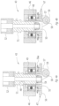
- FIG. 4 a is an enlarged cross-sectional view of the material applicator head mounted on the lower end of the applicator assembly, illustrating the nozzle of a conduit for supplying a molten bead of thermoplastic material fully inserted into a passageway therethrough;
- FIG. 4 b is a view similar to the view of FIG. 4 a , illustrating the nozzle thereof fully inserted into the passageway thereof;
- FIG. 5 is a view similar to the view shown in FIG. 4 a , illustrating a bead of molten material being extruded by the applicator bead shown in FIG. 4 a onto a work surface, and a roller thereof engaging and compressing a portion of such bead against such work surface, forming a ply of an article being formed;
- FIG. 6 a is an enlarged perspective view of the lower end of the assembly shown in FIG. 2 , provided with a roller formed with transversely spaced grooves;
- FIG. 6 b is a view similar to the view shown in FIG. 6 a but with a roller formed with a transversely curved configuration.
- FIG. 1 of the drawings there is illustrated a programmable computer numeric control (CNC) machine embodying the present invention which includes a bed 20 provided with a pair of transversely spaced side walls 21 and 22 , a gantry 23 supported on side walls 21 and 22 , carriage 24 mounted on gantry 23 , a carrier 25 mounted on carriage 24 and an applicator assembly 26 mounted on carrier 25 .
- CNC computer numeric control
- Supported on bed 20 between side walls 21 and 22 is a worktable 27 provided with a support surface disposed in an x-y plane, which may be fixed or displaceable along an x-axis.
- the worktable is displaceable along a set of rails mounted on the bed by means of servomotors mounted on the bed and operatively connected to the worktable.
- Gantry 23 is disposed along a y-axis, supported at the ends thereof on end walls 21 and 22 , either fixedly or displaceably along an x-axis on a set of guide rails 28 and 29 provided on the uppers ends of side walls 21 and 23 .
- the gantry is displaceable by a set of servomotors mounted on the gantry and operatively connected to tracks provided on the side walls of the bed.
- Carriage 24 is supported on gantry 23 and is provided with a support member 30 mounted on and displaceable along a set of guide rails 31 , 32 and 33 provided on the gantry. It is displaceable along a y-axis on such rails by a servomotor mounted on the gantry and operatively connected to support member 30 .
- Carrier 25 is mounted on a set of spaced, vertically disposed guide rails 34 and 35 supported on the carriage for displacement of the carrier relative to the carriage along a z-axis. It is displaceable along such axis by a servomotor mounted on the carriage and operatively connected to the carrier.
- carrier 25 is provided with a base platform 36 , a gear box 37 fixedly mounted in the upper side thereof and a mounting platform 38 rotatably mounted on the underside thereof, provided with openings therethrough disposed along the z-axis of the carrier.
- Such gear box is provided with a gear arrangement provided with an opening therethrough disposed coaxially with the aligned openings in gear box 37 and platforms 36 and 38 , operatively connected to platform 38 for rotation about such x-axis, and rotatable about such axis by means of a servomotor 39 mounted on base platform 36 and operatively connected to such gear arrangement.
- Applicator assembly 26 includes an upper segment 41 and a lower segment 42 .
- Segment 41 includes a transverse portion 41 a secured to the underside of mounting platform 38 for rotational movement about the z-axis, provided with an opening therethrough along such z-axis, and a depending portion 41 disposed laterally relative to such axis.
- Segment 42 consisting of a housing disposed on an inner side of depending segment portion 41 b , is mounted on a shaft journalled in a lower end of portion 41 b , intersecting and disposed perpendicular to the z-axis of carrier 25 , and further is provided with a laterally projecting application head 43 at a free end thereof.
- Mounted on a bracket 44 provided on an outer side of segment portion 41 b is a servomotor 45 operatively connected to the shaft journalled in portion 41 b for pivotally displacing segment 42 in y-z plane.
- applicator head 43 includes a housing 46 mounted on and projecting laterally from the lower end of segment 42 , and a bracket 47 .
- Housing 46 is provided with a cylindrical opening 48 therethrough provided with an enlarged portion, a roller bearing 49 mounted in such enlarged portion of such opening and a cylindrical sleeve 50 disposed in such enlarged portion, mounted on the inner race of such bearing, having an inner diameter corresponding to opening 48 and including a portion extending beyond housing 46 .
- Housing opening 48 and sleeve 50 are configured to receive therein a nozzle 51 of a flexible conduit 52 for conveying and extruding a molten bead 53 of a thermoplastic material through such nozzle provided with an output die 54 as shown in FIG. 5 .
- Bracket 47 includes an annular base portion 55 coaxially mounted on the lower, exposed end of sleeve 50 and rotatable with sleeve 50 about the axis thereof, an annular plate portion 56 coaxially mounted on annular base portion 55 and spaced axially relative to bearing 49 , and a sprocket 56 a mounted on base portion 55 , coaxially on exposed portion 55 .
- Bracket 47 further includes a pair of spaced depending brackets 57 , 57 supporting a shaft 58 on which there is mounted a rotatable roller 59 .
- the axis of rotation of shaft 58 is disposed along the line of intersection of a first plane disposed perpendicular to the axis of passageway 48 and a second plane disposed parallel to such axis.
- bracket 47 is rotatably displaceable about the axis thereof by a servomotor 60 supported on an L-shaped bracket 61 mounted on a lower rear side of lower applicator segment 42 , having an output shaft 62 projecting through an opening 63 in bracket 61 , provided with a sprocket 64 drivingly connected to sprocket 56 by means of a belt 65 .
- Conduit 52 consists of an elongated, flexible material for conducting a molten bead of a thermoplastic material under pressure from a source disposed on carrier 25 or another source, to applicator head 43 .
- An intermediate portion of such conduit is routed through the openings through gear box 37 , support platform 36 and mounting platform 38 , along the z-axis of carrier 25 .
- Such material is heated sufficiently to form a molten bead thereof, readily guide such bead through conduit 52 and extrude it through applicator head 43 in forming a strata of plies fusing together in forming an article.
- Such material supplied through such conduit and extruded to form an article may be provided with fibers which facilitate and enhance the fusion of extruded, engaging plies.
- a bead of molten material would be extruded along a defined path either on support surface 27 of the machine or previously extruder plies of such material, ahead of the path of roller 59 , and caused to be engaged and compressed by such roller either against such support surface of a previously applied heated ply of material, fusing such plies together to form an object consisting of a strata of material plies fused together forming either an end product or an oversized, near duplicate thereof.
- control system of the machine in executing the inputted program, would operate the several servomotors as described to displace the support surface or gantry along the x-axis, displace the carriage along the y-axis, displace the carrier along a z-axis, pivot lower applicator segment 42 about an axis disposed in an x-y plane and rotate bracket 47 about a z-axis thereof, pursuant to the inputted program, to provide the described end product or an oversized, near duplicate thereof.
- roller 59 may be cylindrical as shown in FIG. 5 , serrated as shown in FIG. 6 a or curved along the length thereof as shown in FIG. 6 b .
- a roller with an irregular surface as shown in FIG. 6 a which is effective in causing outlying portions of such fibers to engage and penetrate heated adjacent plies, enhancing the fusion of such plies.
- an article may be formed simply by forming a strata of plies defining the intended final configuration of the article; forming a strata of plies defining an interim configuration minimally exceeding the intended final configuration and then machining such interim configuration to provide the final configuration thereof; providing a permanent substructure preferably of a metal, having a configuration smaller than the intended final configuration of the article, and forming a strata of plies on such substructure providing the intended final configuration of the article; providing a permanent substructure preferably of a metal, having a configuration smaller than the intended final configuration of the article, forming a strata of plies on such substructure in forming an interim configuration slightly greater than the intended final configuration and then machining such interim configuration to provide the intended final configuration; providing a mold having a configuration smaller than the intended final configuration of the article, forming a strata of plies on such mold slightly greater than the intended final configuration of the article, machining such interim configuration to provide the final configuration of the article and then removing such mold; and providing a mold having a configuration smaller than the intended final configuration
Landscapes
- Engineering & Computer Science (AREA)
- Chemical & Material Sciences (AREA)
- Materials Engineering (AREA)
- Mechanical Engineering (AREA)
- Physics & Mathematics (AREA)
- Manufacturing & Machinery (AREA)
- Optics & Photonics (AREA)
- Extrusion Moulding Of Plastics Or The Like (AREA)
Abstract
Description
Claims (20)
Priority Applications (3)
| Application Number | Priority Date | Filing Date | Title |
|---|---|---|---|
| US18/045,048 US11865760B2 (en) | 2015-12-28 | 2022-10-07 | Machine and method for forming articles |
| US18/529,979 US12233586B2 (en) | 2015-12-28 | 2023-12-05 | Machine and method for forming articles |
| US19/024,559 US20250153412A1 (en) | 2015-12-28 | 2025-01-16 | Machine and method for forming articles |
Applications Claiming Priority (5)
| Application Number | Priority Date | Filing Date | Title |
|---|---|---|---|
| US14/980,818 US10611073B2 (en) | 2015-12-28 | 2015-12-28 | Machine and method for forming articles |
| US16/403,079 US10668657B2 (en) | 2015-12-28 | 2019-05-03 | Machine and method for forming articles |
| US16/861,490 US11014279B2 (en) | 2015-12-28 | 2020-04-29 | Machine and method for forming articles |
| US17/322,540 US11491696B2 (en) | 2015-12-28 | 2021-05-17 | Machine and method for forming articles |
| US18/045,048 US11865760B2 (en) | 2015-12-28 | 2022-10-07 | Machine and method for forming articles |
Related Parent Applications (1)
| Application Number | Title | Priority Date | Filing Date |
|---|---|---|---|
| US17/322,540 Continuation US11491696B2 (en) | 2015-12-28 | 2021-05-17 | Machine and method for forming articles |
Related Child Applications (1)
| Application Number | Title | Priority Date | Filing Date |
|---|---|---|---|
| US18/529,979 Continuation US12233586B2 (en) | 2015-12-28 | 2023-12-05 | Machine and method for forming articles |
Publications (2)
| Publication Number | Publication Date |
|---|---|
| US20230056184A1 US20230056184A1 (en) | 2023-02-23 |
| US11865760B2 true US11865760B2 (en) | 2024-01-09 |
Family
ID=56787671
Family Applications (8)
| Application Number | Title | Priority Date | Filing Date |
|---|---|---|---|
| US14/980,818 Active 2037-07-11 US10611073B2 (en) | 2015-12-28 | 2015-12-28 | Machine and method for forming articles |
| US15/950,778 Active US10286588B2 (en) | 2015-12-28 | 2018-04-11 | Machine and method for forming articles |
| US16/403,079 Active US10668657B2 (en) | 2015-12-28 | 2019-05-03 | Machine and method for forming articles |
| US16/861,490 Active 2036-01-02 US11014279B2 (en) | 2015-12-28 | 2020-04-29 | Machine and method for forming articles |
| US17/322,540 Active US11491696B2 (en) | 2015-12-28 | 2021-05-17 | Machine and method for forming articles |
| US18/045,048 Active 2035-12-28 US11865760B2 (en) | 2015-12-28 | 2022-10-07 | Machine and method for forming articles |
| US18/529,979 Active US12233586B2 (en) | 2015-12-28 | 2023-12-05 | Machine and method for forming articles |
| US19/024,559 Pending US20250153412A1 (en) | 2015-12-28 | 2025-01-16 | Machine and method for forming articles |
Family Applications Before (5)
| Application Number | Title | Priority Date | Filing Date |
|---|---|---|---|
| US14/980,818 Active 2037-07-11 US10611073B2 (en) | 2015-12-28 | 2015-12-28 | Machine and method for forming articles |
| US15/950,778 Active US10286588B2 (en) | 2015-12-28 | 2018-04-11 | Machine and method for forming articles |
| US16/403,079 Active US10668657B2 (en) | 2015-12-28 | 2019-05-03 | Machine and method for forming articles |
| US16/861,490 Active 2036-01-02 US11014279B2 (en) | 2015-12-28 | 2020-04-29 | Machine and method for forming articles |
| US17/322,540 Active US11491696B2 (en) | 2015-12-28 | 2021-05-17 | Machine and method for forming articles |
Family Applications After (2)
| Application Number | Title | Priority Date | Filing Date |
|---|---|---|---|
| US18/529,979 Active US12233586B2 (en) | 2015-12-28 | 2023-12-05 | Machine and method for forming articles |
| US19/024,559 Pending US20250153412A1 (en) | 2015-12-28 | 2025-01-16 | Machine and method for forming articles |
Country Status (4)
| Country | Link |
|---|---|
| US (8) | US10611073B2 (en) |
| EP (1) | EP3397457B1 (en) |
| CA (1) | CA3002964C (en) |
| WO (1) | WO2017116507A1 (en) |
Cited By (1)
| Publication number | Priority date | Publication date | Assignee | Title |
|---|---|---|---|---|
| US20250153412A1 (en) * | 2015-12-28 | 2025-05-15 | Thermwood Corporation | Machine and method for forming articles |
Families Citing this family (15)
| Publication number | Priority date | Publication date | Assignee | Title |
|---|---|---|---|---|
| EP3218160A4 (en) * | 2014-11-14 | 2018-10-17 | Nielsen-Cole, Cole | Additive manufacturing techniques and systems to form composite materials |
| US10071525B2 (en) * | 2017-02-07 | 2018-09-11 | Thermwood Corporation | Apparatus and method for printing long composite thermoplastic parts on a dual gantry machine during additive manufacturing |
| US10875244B2 (en) * | 2017-05-17 | 2020-12-29 | Slice Engineering LLC | Adaptable high-performance extrusion head for fused filament fabrication systems |
| US10786946B2 (en) * | 2017-09-13 | 2020-09-29 | Thermwood Corporation | Apparatus and methods for compressing material during additive manufacturing |
| US10933586B2 (en) | 2017-09-13 | 2021-03-02 | Thermwood Corporation | Apparatus and method for printing large thermoplastic parts during additive manufacturing |
| US10245788B1 (en) * | 2018-02-14 | 2019-04-02 | Thermwood Corporation | Methods and apparatus for thermal compensation during additive manufacturing |
| US11383437B2 (en) * | 2018-10-02 | 2022-07-12 | Dongming Hu | Hybrid manufacturing apparatus |
| US10786944B1 (en) | 2019-11-22 | 2020-09-29 | Thermwood Corporation | Near net shape additive manufacturing |
| CN111497225A (en) * | 2020-04-03 | 2020-08-07 | 江南大学 | Nozzle, printer and printing method suitable for continuous fiber reinforced composite materials |
| US11577468B2 (en) * | 2020-04-03 | 2023-02-14 | Korea Institute Of Energy Research | 3-D printing apparatus for fabricating supercapacitor or secondary battery |
| USD980882S1 (en) * | 2020-12-31 | 2023-03-14 | Slice Engineering, Llc | 3D printer hotend |
| US11618209B1 (en) | 2022-03-24 | 2023-04-04 | Thermwood Corporation | Apparatus and method for depositing material during additive manufacturing |
| CN115122629A (en) * | 2022-06-30 | 2022-09-30 | 上海酷鹰机器人科技有限公司 | A compaction shaping device for large-scale 3D printing |
| DE102023107846A1 (en) | 2023-03-28 | 2024-10-02 | Peri Se | Device and method for additive manufacturing of a component |
| DE102023112200A1 (en) * | 2023-05-10 | 2024-11-14 | Kraussmaffei Technologies Gmbh | Pressing device for an additive manufacturing system and manufacturing system equipped therewith |
Citations (33)
| Publication number | Priority date | Publication date | Assignee | Title |
|---|---|---|---|---|
| US4588872A (en) | 1984-03-22 | 1986-05-13 | Bollinger John G | Self-guided welding machine |
| US4909880A (en) | 1988-05-17 | 1990-03-20 | General Dynamics Corporation | Method and apparatus for tape winding on irregular shapes |
| US5700347A (en) | 1996-01-11 | 1997-12-23 | The Boeing Company | Thermoplastic multi-tape application head |
| US6004124A (en) | 1998-01-26 | 1999-12-21 | Stratasys, Inc. | Thin-wall tube liquifier |
| US20040164436A1 (en) | 2003-01-21 | 2004-08-26 | University Of Southern California | Multi-nozzle assembly for extrusion of wall |
| US20050104241A1 (en) | 2000-01-18 | 2005-05-19 | Objet Geometried Ltd. | Apparatus and method for three dimensional model printing |
| US20050141975A1 (en) | 2003-12-24 | 2005-06-30 | Hardesty Michael P. | Toolhead assembly for cnc machines having misalignment prevention means |
| US20070044919A1 (en) | 2005-08-25 | 2007-03-01 | Ingersoll Machine Tools, Inc. | Compact fiber placement apparatus and method of making and using same |
| US20070044899A1 (en) | 2005-08-25 | 2007-03-01 | Ingersoll Machine Tools, Inc. | Add roller for a fiber placement machine |
| US20080006017A1 (en) | 2006-07-10 | 2008-01-10 | Ingersoll Machine Tools, Inc. | Tow Catch For Fiber Placement Head |
| US7731816B2 (en) | 2006-02-16 | 2010-06-08 | Ingersoll Machine Tools, Inc. | System and method for heating carbon fiber using infrared radiation in a fiber placement machine |
| US20100200168A1 (en) | 2009-02-06 | 2010-08-12 | Ingersoll Machine Tools, Inc. | Fiber delivery apparatus and system having a creel and fiber placement head sans fiber redirect |
| US20100206224A1 (en) | 2007-09-24 | 2010-08-19 | Berner Fachhochschule fur Technik und informatik HTI | Device for the deposition of layers |
| US7810539B2 (en) | 2005-08-25 | 2010-10-12 | Ingersoll Machine Tools, Inc. | Compaction roller for a fiber placement machine |
| US8151854B2 (en) | 2007-10-16 | 2012-04-10 | Ingersoll Machine Tools, Inc. | Fiber placement machine platform system having interchangeable head and creel assemblies |
| US20120222810A1 (en) | 2011-03-02 | 2012-09-06 | Vaniglia Milo M | Reversing fiber placement head |
| WO2013064826A1 (en) | 2011-11-01 | 2013-05-10 | Loughborough University | Method and apparatus for delivery of cementitious material |
| US20130142898A1 (en) | 2011-12-05 | 2013-06-06 | Mag Ias, Llc | Fiber delivery system for composite part manufacture |
| US20130197683A1 (en) | 2010-04-15 | 2013-08-01 | Huazhong University Of Science And Technology | Method for manufacturing metal parts and molds and micro-roller used therefor |
| US8534338B2 (en) | 2010-10-15 | 2013-09-17 | Ingersoll Machine Tools, Inc. | Fiber delivery apparatus and system having a creel and fiber placement head with polar axis of rotation |
| US8954180B2 (en) | 2010-08-06 | 2015-02-10 | Ingersoll Machine Tools, Inc. | Manufacturing process and apparatus having an interchangeable machine tool head with integrated control |
| US20150048553A1 (en) | 2013-07-24 | 2015-02-19 | The Boeing Company | Additive-manufacturing systems, apparatuses and methods |
| US20150108677A1 (en) | 2013-03-22 | 2015-04-23 | Markforged, Inc. | Three dimensional printer with composite filament fabrication |
| US20150174824A1 (en) | 2013-12-19 | 2015-06-25 | Karl Joseph Gifford | Systems and methods for 3D printing with multiple exchangeable printheads |
| US20150224699A1 (en) | 2014-02-07 | 2015-08-13 | The Boeing Company | Extrusion apparatus and method |
| US20150290875A1 (en) | 2013-03-22 | 2015-10-15 | Markforged, Inc. | Three dimensional printing of composite reinforced structures |
| US20150367576A1 (en) | 2014-06-19 | 2015-12-24 | Autodesk, Inc. | Automated systems for composite part fabrication |
| US20160144564A1 (en) | 2014-07-18 | 2016-05-26 | Fusion3 Design LLC | Apparatus and method for fabricating three-dimensional objects |
| US20160263822A1 (en) | 2013-10-30 | 2016-09-15 | R. Platt Boyd, IV | Additive manufacturing of building and other structures |
| US20170028633A1 (en) * | 2015-07-31 | 2017-02-02 | The Boeing Company | Systems and methods for additively manufacturing composite parts |
| US20170028634A1 (en) | 2015-07-31 | 2017-02-02 | The Boeing Company | Systems and methods for additively manufacturing composite parts |
| US20170203506A1 (en) | 2014-07-22 | 2017-07-20 | Stratasys, Inc. | Gear-based liquefier assembly for additive manufacturing system, and methods of use thereof |
| US20180050502A1 (en) | 2016-08-19 | 2018-02-22 | Ingersoll Machine Tools, Inc. | Fiber placement head with secondary compaction arrangement |
Family Cites Families (5)
| Publication number | Priority date | Publication date | Assignee | Title |
|---|---|---|---|---|
| US8220514B2 (en) * | 2005-06-10 | 2012-07-17 | North Cutting Systems, Llc | Tape laying apparatus and method |
| WO2010023535A1 (en) | 2008-08-25 | 2010-03-04 | Jubilant Organosys Limited | A process for producing (s)-3-[(1-dimethylamino)ethyl] phenyl-n-ethyl-n-methyl-carbamate via novel intermediates |
| US9713902B2 (en) * | 2015-05-01 | 2017-07-25 | Thermwood Corporation | Additive manufacturing apparatus |
| US20180321659A1 (en) * | 2015-11-06 | 2018-11-08 | Sabic Global Technologies B.V. | Systems and methods for optimization of 3-d printed objects |
| US10611073B2 (en) * | 2015-12-28 | 2020-04-07 | Thermwood Corporation | Machine and method for forming articles |
-
2015
- 2015-12-28 US US14/980,818 patent/US10611073B2/en active Active
-
2016
- 2016-07-27 WO PCT/US2016/044159 patent/WO2017116507A1/en not_active Ceased
- 2016-07-27 EP EP16754581.3A patent/EP3397457B1/en active Active
- 2016-07-27 CA CA3002964A patent/CA3002964C/en active Active
-
2018
- 2018-04-11 US US15/950,778 patent/US10286588B2/en active Active
-
2019
- 2019-05-03 US US16/403,079 patent/US10668657B2/en active Active
-
2020
- 2020-04-29 US US16/861,490 patent/US11014279B2/en active Active
-
2021
- 2021-05-17 US US17/322,540 patent/US11491696B2/en active Active
-
2022
- 2022-10-07 US US18/045,048 patent/US11865760B2/en active Active
-
2023
- 2023-12-05 US US18/529,979 patent/US12233586B2/en active Active
-
2025
- 2025-01-16 US US19/024,559 patent/US20250153412A1/en active Pending
Patent Citations (35)
| Publication number | Priority date | Publication date | Assignee | Title |
|---|---|---|---|---|
| US4588872A (en) | 1984-03-22 | 1986-05-13 | Bollinger John G | Self-guided welding machine |
| US4909880A (en) | 1988-05-17 | 1990-03-20 | General Dynamics Corporation | Method and apparatus for tape winding on irregular shapes |
| US5700347A (en) | 1996-01-11 | 1997-12-23 | The Boeing Company | Thermoplastic multi-tape application head |
| US6004124A (en) | 1998-01-26 | 1999-12-21 | Stratasys, Inc. | Thin-wall tube liquifier |
| US20050104241A1 (en) | 2000-01-18 | 2005-05-19 | Objet Geometried Ltd. | Apparatus and method for three dimensional model printing |
| US20100318222A1 (en) | 2003-01-21 | 2010-12-16 | University Of Southern California | Automated plumbing, wiring, and reinforcement |
| US20040164436A1 (en) | 2003-01-21 | 2004-08-26 | University Of Southern California | Multi-nozzle assembly for extrusion of wall |
| US20050141975A1 (en) | 2003-12-24 | 2005-06-30 | Hardesty Michael P. | Toolhead assembly for cnc machines having misalignment prevention means |
| US20070044899A1 (en) | 2005-08-25 | 2007-03-01 | Ingersoll Machine Tools, Inc. | Add roller for a fiber placement machine |
| US7810539B2 (en) | 2005-08-25 | 2010-10-12 | Ingersoll Machine Tools, Inc. | Compaction roller for a fiber placement machine |
| US20070044919A1 (en) | 2005-08-25 | 2007-03-01 | Ingersoll Machine Tools, Inc. | Compact fiber placement apparatus and method of making and using same |
| US7731816B2 (en) | 2006-02-16 | 2010-06-08 | Ingersoll Machine Tools, Inc. | System and method for heating carbon fiber using infrared radiation in a fiber placement machine |
| US20080006017A1 (en) | 2006-07-10 | 2008-01-10 | Ingersoll Machine Tools, Inc. | Tow Catch For Fiber Placement Head |
| US20100206224A1 (en) | 2007-09-24 | 2010-08-19 | Berner Fachhochschule fur Technik und informatik HTI | Device for the deposition of layers |
| US8151854B2 (en) | 2007-10-16 | 2012-04-10 | Ingersoll Machine Tools, Inc. | Fiber placement machine platform system having interchangeable head and creel assemblies |
| US20100200168A1 (en) | 2009-02-06 | 2010-08-12 | Ingersoll Machine Tools, Inc. | Fiber delivery apparatus and system having a creel and fiber placement head sans fiber redirect |
| US20130197683A1 (en) | 2010-04-15 | 2013-08-01 | Huazhong University Of Science And Technology | Method for manufacturing metal parts and molds and micro-roller used therefor |
| US8954180B2 (en) | 2010-08-06 | 2015-02-10 | Ingersoll Machine Tools, Inc. | Manufacturing process and apparatus having an interchangeable machine tool head with integrated control |
| US8534338B2 (en) | 2010-10-15 | 2013-09-17 | Ingersoll Machine Tools, Inc. | Fiber delivery apparatus and system having a creel and fiber placement head with polar axis of rotation |
| US20120222810A1 (en) | 2011-03-02 | 2012-09-06 | Vaniglia Milo M | Reversing fiber placement head |
| WO2013064826A1 (en) | 2011-11-01 | 2013-05-10 | Loughborough University | Method and apparatus for delivery of cementitious material |
| US20130142898A1 (en) | 2011-12-05 | 2013-06-06 | Mag Ias, Llc | Fiber delivery system for composite part manufacture |
| US20150290875A1 (en) | 2013-03-22 | 2015-10-15 | Markforged, Inc. | Three dimensional printing of composite reinforced structures |
| US20150108677A1 (en) | 2013-03-22 | 2015-04-23 | Markforged, Inc. | Three dimensional printer with composite filament fabrication |
| US20150048553A1 (en) | 2013-07-24 | 2015-02-19 | The Boeing Company | Additive-manufacturing systems, apparatuses and methods |
| US20160263822A1 (en) | 2013-10-30 | 2016-09-15 | R. Platt Boyd, IV | Additive manufacturing of building and other structures |
| US20150174824A1 (en) | 2013-12-19 | 2015-06-25 | Karl Joseph Gifford | Systems and methods for 3D printing with multiple exchangeable printheads |
| US20150224699A1 (en) | 2014-02-07 | 2015-08-13 | The Boeing Company | Extrusion apparatus and method |
| US20150367576A1 (en) | 2014-06-19 | 2015-12-24 | Autodesk, Inc. | Automated systems for composite part fabrication |
| US20160144564A1 (en) | 2014-07-18 | 2016-05-26 | Fusion3 Design LLC | Apparatus and method for fabricating three-dimensional objects |
| US20170203506A1 (en) | 2014-07-22 | 2017-07-20 | Stratasys, Inc. | Gear-based liquefier assembly for additive manufacturing system, and methods of use thereof |
| US20170028633A1 (en) * | 2015-07-31 | 2017-02-02 | The Boeing Company | Systems and methods for additively manufacturing composite parts |
| US20170028634A1 (en) | 2015-07-31 | 2017-02-02 | The Boeing Company | Systems and methods for additively manufacturing composite parts |
| US20170028434A1 (en) | 2015-07-31 | 2017-02-02 | The Boeing Company | Systems and methods for additively manufacturing composite parts |
| US20180050502A1 (en) | 2016-08-19 | 2018-02-22 | Ingersoll Machine Tools, Inc. | Fiber placement head with secondary compaction arrangement |
Non-Patent Citations (2)
| Title |
|---|
| International Search Report and Written Opinion in corresponding International Application No. PCT/US2016/044159, dated Oct. 19, 2016, 13 pages. |
| Oberg, Erik Jones, Franklin D. Horton, Holbrook L. Ryffel, Henry H., (2012); Machinery's Handbook (29th Edition) & Guide to Machinery's Handbook; Industrial Press, Retrieved from: https://app.knovel.com/hotlink/toc/id:kpMHEGMH24/machinerys-handbook-29th/machinerys-handbook-29th. |
Cited By (1)
| Publication number | Priority date | Publication date | Assignee | Title |
|---|---|---|---|---|
| US20250153412A1 (en) * | 2015-12-28 | 2025-05-15 | Thermwood Corporation | Machine and method for forming articles |
Also Published As
| Publication number | Publication date |
|---|---|
| US20170182698A1 (en) | 2017-06-29 |
| EP3397457B1 (en) | 2021-03-24 |
| US11491696B2 (en) | 2022-11-08 |
| WO2017116507A1 (en) | 2017-07-06 |
| US20190255752A1 (en) | 2019-08-22 |
| US20230056184A1 (en) | 2023-02-23 |
| US11014279B2 (en) | 2021-05-25 |
| US20250153412A1 (en) | 2025-05-15 |
| US10668657B2 (en) | 2020-06-02 |
| US10286588B2 (en) | 2019-05-14 |
| US10611073B2 (en) | 2020-04-07 |
| US12233586B2 (en) | 2025-02-25 |
| EP3397457A1 (en) | 2018-11-07 |
| US20210268709A1 (en) | 2021-09-02 |
| US20200254674A1 (en) | 2020-08-13 |
| CA3002964C (en) | 2021-06-01 |
| CA3002964A1 (en) | 2017-07-06 |
| US20180229416A1 (en) | 2018-08-16 |
| US20240123669A1 (en) | 2024-04-18 |
Similar Documents
| Publication | Publication Date | Title |
|---|---|---|
| US11865760B2 (en) | Machine and method for forming articles | |
| US12343929B2 (en) | Apparatus and methods for fabricating components | |
| US10065361B2 (en) | Apparatus and method for printing long composite thermoplastic parts on a dual gantry machine during additive manufacturing | |
| US12605883B2 (en) | Methods and apparatus for compensating for material distortion during additive manufacturing | |
| US10549477B2 (en) | Methods and apparatus for controlling an applicator head during additive manufacturing | |
| US20170355138A1 (en) | Wear resistance in 3d printing of composites | |
| US10632683B2 (en) | Methods and apparatus for thermal compensation during additive manufacturing | |
| US20250162240A1 (en) | Near net shape additive manufacturing system | |
| JP2023143835A (en) | Apparatus and method for depositing material during additive manufacturing |
Legal Events
| Date | Code | Title | Description |
|---|---|---|---|
| FEPP | Fee payment procedure |
Free format text: ENTITY STATUS SET TO UNDISCOUNTED (ORIGINAL EVENT CODE: BIG.); ENTITY STATUS OF PATENT OWNER: SMALL ENTITY |
|
| AS | Assignment |
Owner name: THERMWOOD CORPORATION, INDIANA Free format text: ASSIGNMENT OF ASSIGNORS INTEREST;ASSIGNOR:SUSNJARA, KENNETH J.;REEL/FRAME:061670/0156 Effective date: 20151214 |
|
| FEPP | Fee payment procedure |
Free format text: ENTITY STATUS SET TO SMALL (ORIGINAL EVENT CODE: SMAL); ENTITY STATUS OF PATENT OWNER: SMALL ENTITY |
|
| STPP | Information on status: patent application and granting procedure in general |
Free format text: FINAL REJECTION MAILED |
|
| STPP | Information on status: patent application and granting procedure in general |
Free format text: DOCKETED NEW CASE - READY FOR EXAMINATION |
|
| STPP | Information on status: patent application and granting procedure in general |
Free format text: NOTICE OF ALLOWANCE MAILED -- APPLICATION RECEIVED IN OFFICE OF PUBLICATIONS |
|
| STPP | Information on status: patent application and granting procedure in general |
Free format text: PUBLICATIONS -- ISSUE FEE PAYMENT RECEIVED |
|
| STPP | Information on status: patent application and granting procedure in general |
Free format text: PUBLICATIONS -- ISSUE FEE PAYMENT VERIFIED |
|
| STCF | Information on status: patent grant |
Free format text: PATENTED CASE |