EP3397457B1 - Machine and method for forming articles - Google Patents
Machine and method for forming articles Download PDFInfo
- Publication number
- EP3397457B1 EP3397457B1 EP16754581.3A EP16754581A EP3397457B1 EP 3397457 B1 EP3397457 B1 EP 3397457B1 EP 16754581 A EP16754581 A EP 16754581A EP 3397457 B1 EP3397457 B1 EP 3397457B1
- Authority
- EP
- European Patent Office
- Prior art keywords
- axis
- bead
- roller
- disposed
- machine
- Prior art date
- Legal status (The legal status is an assumption and is not a legal conclusion. Google has not performed a legal analysis and makes no representation as to the accuracy of the status listed.)
- Active
Links
- 238000000034 method Methods 0.000 title claims description 13
- 239000000463 material Substances 0.000 claims description 36
- 239000011324 bead Substances 0.000 claims description 34
- 239000012815 thermoplastic material Substances 0.000 claims description 11
- 239000012768 molten material Substances 0.000 claims description 7
- 239000012783 reinforcing fiber Substances 0.000 claims description 7
- 230000013011 mating Effects 0.000 claims description 2
- 238000003825 pressing Methods 0.000 claims 2
- 238000000151 deposition Methods 0.000 claims 1
- 230000003292 diminished effect Effects 0.000 claims 1
- 238000003754 machining Methods 0.000 description 5
- 239000000654 additive Substances 0.000 description 4
- 230000000996 additive effect Effects 0.000 description 4
- 230000004927 fusion Effects 0.000 description 4
- 238000004519 manufacturing process Methods 0.000 description 4
- 239000007795 chemical reaction product Substances 0.000 description 3
- 239000004033 plastic Substances 0.000 description 3
- 238000001125 extrusion Methods 0.000 description 2
- 239000000835 fiber Substances 0.000 description 2
- 239000002184 metal Substances 0.000 description 2
- 238000010146 3D printing Methods 0.000 description 1
- 230000001351 cycling effect Effects 0.000 description 1
- 238000005137 deposition process Methods 0.000 description 1
- 238000006073 displacement reaction Methods 0.000 description 1
- 230000002708 enhancing effect Effects 0.000 description 1
- 230000010354 integration Effects 0.000 description 1
- 230000001788 irregular Effects 0.000 description 1
- 239000012778 molding material Substances 0.000 description 1
- 239000012779 reinforcing material Substances 0.000 description 1
- 239000007787 solid Substances 0.000 description 1
- 229920001169 thermoplastic Polymers 0.000 description 1
- 239000004416 thermosoftening plastic Substances 0.000 description 1
Images


Classifications
-
- B—PERFORMING OPERATIONS; TRANSPORTING
- B29—WORKING OF PLASTICS; WORKING OF SUBSTANCES IN A PLASTIC STATE IN GENERAL
- B29C—SHAPING OR JOINING OF PLASTICS; SHAPING OF MATERIAL IN A PLASTIC STATE, NOT OTHERWISE PROVIDED FOR; AFTER-TREATMENT OF THE SHAPED PRODUCTS, e.g. REPAIRING
- B29C64/00—Additive manufacturing, i.e. manufacturing of three-dimensional [3D] objects by additive deposition, additive agglomeration or additive layering, e.g. by 3D printing, stereolithography or selective laser sintering
- B29C64/10—Processes of additive manufacturing
- B29C64/188—Processes of additive manufacturing involving additional operations performed on the added layers, e.g. smoothing, grinding or thickness control
-
- B—PERFORMING OPERATIONS; TRANSPORTING
- B29—WORKING OF PLASTICS; WORKING OF SUBSTANCES IN A PLASTIC STATE IN GENERAL
- B29C—SHAPING OR JOINING OF PLASTICS; SHAPING OF MATERIAL IN A PLASTIC STATE, NOT OTHERWISE PROVIDED FOR; AFTER-TREATMENT OF THE SHAPED PRODUCTS, e.g. REPAIRING
- B29C43/00—Compression moulding, i.e. applying external pressure to flow the moulding material; Apparatus therefor
- B29C43/02—Compression moulding, i.e. applying external pressure to flow the moulding material; Apparatus therefor of articles of definite length, i.e. discrete articles
- B29C43/20—Making multilayered or multicoloured articles
- B29C43/203—Making multilayered articles
-
- B—PERFORMING OPERATIONS; TRANSPORTING
- B29—WORKING OF PLASTICS; WORKING OF SUBSTANCES IN A PLASTIC STATE IN GENERAL
- B29C—SHAPING OR JOINING OF PLASTICS; SHAPING OF MATERIAL IN A PLASTIC STATE, NOT OTHERWISE PROVIDED FOR; AFTER-TREATMENT OF THE SHAPED PRODUCTS, e.g. REPAIRING
- B29C48/00—Extrusion moulding, i.e. expressing the moulding material through a die or nozzle which imparts the desired form; Apparatus therefor
- B29C48/16—Articles comprising two or more components, e.g. co-extruded layers
- B29C48/18—Articles comprising two or more components, e.g. co-extruded layers the components being layers
-
- B—PERFORMING OPERATIONS; TRANSPORTING
- B29—WORKING OF PLASTICS; WORKING OF SUBSTANCES IN A PLASTIC STATE IN GENERAL
- B29C—SHAPING OR JOINING OF PLASTICS; SHAPING OF MATERIAL IN A PLASTIC STATE, NOT OTHERWISE PROVIDED FOR; AFTER-TREATMENT OF THE SHAPED PRODUCTS, e.g. REPAIRING
- B29C64/00—Additive manufacturing, i.e. manufacturing of three-dimensional [3D] objects by additive deposition, additive agglomeration or additive layering, e.g. by 3D printing, stereolithography or selective laser sintering
- B29C64/10—Processes of additive manufacturing
- B29C64/106—Processes of additive manufacturing using only liquids or viscous materials, e.g. depositing a continuous bead of viscous material
- B29C64/118—Processes of additive manufacturing using only liquids or viscous materials, e.g. depositing a continuous bead of viscous material using filamentary material being melted, e.g. fused deposition modelling [FDM]
-
- B—PERFORMING OPERATIONS; TRANSPORTING
- B29—WORKING OF PLASTICS; WORKING OF SUBSTANCES IN A PLASTIC STATE IN GENERAL
- B29C—SHAPING OR JOINING OF PLASTICS; SHAPING OF MATERIAL IN A PLASTIC STATE, NOT OTHERWISE PROVIDED FOR; AFTER-TREATMENT OF THE SHAPED PRODUCTS, e.g. REPAIRING
- B29C64/00—Additive manufacturing, i.e. manufacturing of three-dimensional [3D] objects by additive deposition, additive agglomeration or additive layering, e.g. by 3D printing, stereolithography or selective laser sintering
- B29C64/20—Apparatus for additive manufacturing; Details thereof or accessories therefor
- B29C64/205—Means for applying layers
- B29C64/209—Heads; Nozzles
-
- B—PERFORMING OPERATIONS; TRANSPORTING
- B29—WORKING OF PLASTICS; WORKING OF SUBSTANCES IN A PLASTIC STATE IN GENERAL
- B29C—SHAPING OR JOINING OF PLASTICS; SHAPING OF MATERIAL IN A PLASTIC STATE, NOT OTHERWISE PROVIDED FOR; AFTER-TREATMENT OF THE SHAPED PRODUCTS, e.g. REPAIRING
- B29C64/00—Additive manufacturing, i.e. manufacturing of three-dimensional [3D] objects by additive deposition, additive agglomeration or additive layering, e.g. by 3D printing, stereolithography or selective laser sintering
- B29C64/20—Apparatus for additive manufacturing; Details thereof or accessories therefor
- B29C64/227—Driving means
- B29C64/236—Driving means for motion in a direction within the plane of a layer
-
- B—PERFORMING OPERATIONS; TRANSPORTING
- B29—WORKING OF PLASTICS; WORKING OF SUBSTANCES IN A PLASTIC STATE IN GENERAL
- B29C—SHAPING OR JOINING OF PLASTICS; SHAPING OF MATERIAL IN A PLASTIC STATE, NOT OTHERWISE PROVIDED FOR; AFTER-TREATMENT OF THE SHAPED PRODUCTS, e.g. REPAIRING
- B29C64/00—Additive manufacturing, i.e. manufacturing of three-dimensional [3D] objects by additive deposition, additive agglomeration or additive layering, e.g. by 3D printing, stereolithography or selective laser sintering
- B29C64/20—Apparatus for additive manufacturing; Details thereof or accessories therefor
- B29C64/25—Housings, e.g. machine housings
-
- B—PERFORMING OPERATIONS; TRANSPORTING
- B29—WORKING OF PLASTICS; WORKING OF SUBSTANCES IN A PLASTIC STATE IN GENERAL
- B29C—SHAPING OR JOINING OF PLASTICS; SHAPING OF MATERIAL IN A PLASTIC STATE, NOT OTHERWISE PROVIDED FOR; AFTER-TREATMENT OF THE SHAPED PRODUCTS, e.g. REPAIRING
- B29C70/00—Shaping composites, i.e. plastics material comprising reinforcements, fillers or preformed parts, e.g. inserts
- B29C70/04—Shaping composites, i.e. plastics material comprising reinforcements, fillers or preformed parts, e.g. inserts comprising reinforcements only, e.g. self-reinforcing plastics
- B29C70/28—Shaping operations therefor
- B29C70/30—Shaping by lay-up, i.e. applying fibres, tape or broadsheet on a mould, former or core; Shaping by spray-up, i.e. spraying of fibres on a mould, former or core
- B29C70/38—Automated lay-up, e.g. using robots, laying filaments according to predetermined patterns
-
- B—PERFORMING OPERATIONS; TRANSPORTING
- B29—WORKING OF PLASTICS; WORKING OF SUBSTANCES IN A PLASTIC STATE IN GENERAL
- B29L—INDEXING SCHEME ASSOCIATED WITH SUBCLASS B29C, RELATING TO PARTICULAR ARTICLES
- B29L2009/00—Layered products
-
- B—PERFORMING OPERATIONS; TRANSPORTING
- B33—ADDITIVE MANUFACTURING TECHNOLOGY
- B33Y—ADDITIVE MANUFACTURING, i.e. MANUFACTURING OF THREE-DIMENSIONAL [3-D] OBJECTS BY ADDITIVE DEPOSITION, ADDITIVE AGGLOMERATION OR ADDITIVE LAYERING, e.g. BY 3-D PRINTING, STEREOLITHOGRAPHY OR SELECTIVE LASER SINTERING
- B33Y10/00—Processes of additive manufacturing
-
- B—PERFORMING OPERATIONS; TRANSPORTING
- B33—ADDITIVE MANUFACTURING TECHNOLOGY
- B33Y—ADDITIVE MANUFACTURING, i.e. MANUFACTURING OF THREE-DIMENSIONAL [3-D] OBJECTS BY ADDITIVE DEPOSITION, ADDITIVE AGGLOMERATION OR ADDITIVE LAYERING, e.g. BY 3-D PRINTING, STEREOLITHOGRAPHY OR SELECTIVE LASER SINTERING
- B33Y30/00—Apparatus for additive manufacturing; Details thereof or accessories therefor
Definitions
- This invention relates to a novel machine and method of forming an article.
- an additive manufacturing process which generally consists of forming and extruding a bead of molten thermoplastic material, applying such bead of molten material in a strata of layers to form a facsimile of an article and then machining such facsimile to provide an end product.
- thermoplastic material is infused with a type of reinforcing fiber to enhance its strength.
- the molten bead while still hot and pliable, is tamped down using an oscillating plate to create a flattened layer of material of a specific desired thickness. This process is repeated so that each layer is deposited upon an existing layer to build up a structure.
- the tamping plate is generally configured as a flat plate with a center through-hole, situated concentric with the centerline of the extrusion nozzle, thus providing for effective tamping of the extruded material, regardless of the direction in which the head is moving.
- This tamping plate not only tamps and flattens the thermoplastic bead but also helps fuse it with the previously laid layer of material.
- the principal object of the present invention is achieved by providing a programmable CNC machine in accordance with claim 1 and a method of forming an article on a work surface using said CNC machine in accordance with claim 12.
- the CNC machine may be operable in forming an article supported on a work surface disposed in an x-y plane, either fixed or displaceable along an x-axis; an extruder disposed along an axis fixed or displaceable along an x-axis, displaceable along y and z axes, rotatable about its axis and pivotal about an x-axis; means for supplying a bead of molten plastic material through such extruder; means cooperable with either such work surface or a previously applied ply of such material for guiding and compressing a portion of such bead emanating from such extruder in forming an article consisting of stratified layers of such extruded material; a set of servomotors operable in displacing such components linearly, rotationally and/
- Such means for guiding and compressing a portion of such bead of molten material emanating from such extruder comprises a roller provided with an axis of rotation disposed along a line of intersecting of a first plane disposed perpendicular to the axis of the material emitting passageway of such extruder and a second plane disposed parallel to such passageway axis.
- a roller provided with an axis of rotation disposed along a line of intersecting of a first plane disposed perpendicular to the axis of the material emitting passageway of such extruder and a second plane disposed parallel to such passageway axis.
- such bead of molten material is provided with reinforcing fibers interspersed therein which function to enhance the fusion of adjoining plies of such material, guided and compressed by such roller.
- a programmable computer numeric control (CNC) machine embodying the present invention which includes a bed 20 provided with a pair of transversely spaced side walls 21 and 22, a gantry 23 supported on side walls 21 and 22, carriage 24 mounted on gantry 23, a carrier 25 mounted on carriage 24 and an applicator assembly 26 mounted on carrier 25.
- Supported on bed 20 between side walls 21 and 22 is a worktable 27 provided with a support surface disposed in an x-y plane, which may be fixed or displaceable along an x-axis.
- the worktable is displaceable along a set of rails mounted on the bed by means of servomotors mounted on the bed and operatively connected to the worktable.
- Gantry 23 is disposed along a y-axis, supported at the ends thereof on end walls 21 and 22, either fixedly or displaceably along an x-axis on a set of guide rails 28 and 29 provided on the uppers ends of side walls 21 and 23.
- the gantry is displaceable by a set of servomotors mounted on the gantry and operatively connected to tracks provided on the side walls of the bed.
- Carriage 24 is supported on gantry 23 and is provided with a support member 30 mounted on and displaceable along a set of guide rails 31, 32 and 33 provided on the gantry.
- Carrier 25 is mounted on a set of spaced, vertically disposed guide rails 34 and 35 supported on the carriage for displacement of the carrier relative to the carriage along a z-axis. It is displaceable along such axis by a servomotor mounted on the carriage and operatively connected to the carrier.
- carrier 25 is provided with a base platform 36, a gear box 37 fixedly mounted in the upper side thereof and a mounting platform 38 rotatably mounted on the underside thereof, provided with openings therethrough disposed along the z-axis of the carrier.
- Such gear box is provided with a gear arrangement provided with an opening therethrough disposed coaxially with the aligned openings in gear box 37 and platforms 36 and 38, operatively connected to platform 38 for rotation about such x-axis, and rotatable about such axis by means of a servomotor 39 mounted on base platform 36 and operatively connected to such gear arrangement.
- Applicator assembly 26 includes an upper segment 41 and a lower segment 42.
- Segment 41 includes a transverse portion 41a secured to the underside of mounting platform 38 for rotational movement about the z-axis, provided with an opening therethrough along such z-axis, and a depending portion 41 disposed laterally relative to such axis.
- Segment 42 consisting of a housing disposed on an inner side of depending segment portion 41b, is mounted on a shaft journalled in a lower end of portion 41b, intersecting and disposed perpendicular to the z-axis of carrier 25, and further is provided with a laterally projecting application head 43 at a free end thereof.
- Mounted on a bracket 44 provided on an outer side of segment portion 41b is a servomotor 45 operatively connected to the shaft journalled in portion 41b for pivotally displacing segment 42 in y-z plane.
- applicator head 43 includes a housing 46 mounted on and projecting laterally from the lower end of segment 42, and a bracket 47.
- Housing 46 is provided with a cylindrical opening 48 therethrough provided with an enlarged portion, a roller bearing 49 mounted in such enlarged portion of such opening and a cylindrical sleeve 50 disposed in such enlarged portion, mounted on the inner race of such bearing, having an inner diameter corresponding to opening 48 and including a portion extending beyond housing 46.
- Housing opening 48 and sleeve 50 are configured to receive therein a nozzle 51 of a flexible conduit 52 for conveying and extruding a molten bead 53 of a thermoplastic material through such nozzle provided with an output die 54 as shown in Figure 5 .
- Bracket 47 includes an annular base portion 55 coaxially mounted on the lower, exposed end of sleeve 50 and rotatable with sleeve 50 about the axis thereof, an annular plate portion 56 coaxially mounted on annular base portion 55 and spaced axially relative to bearing 49, and a sprocket 56a mounted on base portion 55, coaxially on exposed portion 55.
- Bracket 47 further includes a pair of spaced depending brackets 57, 57 supporting a shaft 58 on which there is mounted a rotatable roller 59.
- the axis of rotation of shaft 58 is disposed along the line of intersection of a first plane disposed perpendicular to the axis of passageway 48 and a second plane disposed parallel to such axis.
- bracket 47 is rotatably displaceable about the axis thereof by a servomotor 60 supported on an L-shaped bracket 61 mounted on a lower rear side of lower applicator segment 42, having an output shaft 62 projecting through an opening 63 in bracket 61, provided with a sprocket 64 drivingly connected to sprocket 56 by means of a belt 65.
- Conduit 52 consists of an elongated, flexible material for conducting a molten bead of a thermoplastic material under pressure from a source disposed on carrier 25 or another source, to applicator head 43.
- An intermediate portion of such conduit is routed through the openings through gear box 37, support platform 36 and mounting platform 38, along the z-axis of carrier 25.
- Such material is heated sufficiently to form a molten bead thereof, readily guide such bead through conduit 52 and extrude it through applicator head 43 in forming a strata of plies fusing together in forming an article.
- Such material supplied through such conduit and extruded to form an article may be provided with fibers which facilitate and enhance the fusion of extruded, engaging plies.
- a bead of molten material would be extruded along a defined path either on support surface 27 of the machine or previously extruder plies of such material, ahead of the path of roller 59, and caused to be engaged and compressed by such roller either against such support surface of a previously applied heated ply of material, fusing such plies together to form an object consisting of a strata of material plies fused together forming either an end product or an oversized, near duplicate thereof.
- control system of the machine in executing the inputted program, would operate the several servomotors as described to displace the support surface or gantry along the x-axis, displace the carriage along the y-axis, displace the carrier along a z-axis, pivot lower applicator segment 42 about an axis disposed in an x-y plane and rotate bracket 47 about a z-axis thereof, pursuant to the inputted program, to provide the described end product or an oversized, near duplicate thereof.
- roller 59 may be cylindrical as shown in Figure 5 , serrated as shown in Figure 6a or curved along the length thereof as shown in Figure 6b .
- a roller with an irregular surface as shown in Figure 6a which is effective in causing outlying portions of such fibers to engage and penetrate heated adjacent plies, enhancing the fusion of such plies.
- an article may be formed simply by forming a strata of plies defining the intended final configuration of the article; forming a strata of plies defining an interim configuration minimally exceeding the intended final configuration and then machining such interim configuration to provide the final configuration thereof; providing a permanent substructure preferably of a metal, having a configuration smaller than the intended final configuration of the article, and forming a strata of plies on such substructure providing the intended final configuration of the article; providing a permanent substructure preferably of a metal, having a configuration smaller than the intended final configuration of the article, forming a strata of plies on such substructure in forming an interim configuration slightly greater than the intended final configuration and then machining such interim configuration to provide the intended final configuration; providing a mold having a configuration smaller than the intended final configuration of the article, forming a strata of plies on such mold slightly greater than the intended final configuration of the article, machining such interim configuration to provide the final configuration of the article and then removing such mold; and providing a mold having a configuration smaller than the intended final configuration
Description
- This invention relates to a novel machine and method of forming an article.
- In the prior art, there has been developed a process generally referred to as an additive manufacturing process which generally consists of forming and extruding a bead of molten thermoplastic material, applying such bead of molten material in a strata of layers to form a facsimile of an article and then machining such facsimile to provide an end product. Typically, such thermoplastic material is infused with a type of reinforcing fiber to enhance its strength. As a general practice, the molten bead, while still hot and pliable, is tamped down using an oscillating plate to create a flattened layer of material of a specific desired thickness. This process is repeated so that each layer is deposited upon an existing layer to build up a structure. When executed properly, the new material being deposited is of a temperature sufficient enough to allow it to melt and fuse with material previously deposited, thus producing a solid part. The tamping plate is generally configured as a flat plate with a center through-hole, situated concentric with the centerline of the extrusion nozzle, thus providing for effective tamping of the extruded material, regardless of the direction in which the head is moving. This tamping plate not only tamps and flattens the thermoplastic bead but also helps fuse it with the previously laid layer of material.
- In the practice of the aforementioned process, several disadvantages have been encountered; most notably, air pockets, which are trapped between layers of thermoplastic material during the extrusion/deposition process, are simply tamped into the structure. In addition to creating problems during any temperature cycling that might occur after the part has cooled and hardened, such entrained air pockets invariably result in internal voids as well as surface imperfections in the final machined article. A further disadvantage of using a tamping plate is the insufficient integration of reinforcing fibers between layers. When two smooth beads of this material are forced together, the plastic component of the bead tends to fuse with the plastic component of the mating bead, with little or no reinforcing fibers crossing the area where the layers meet. Consequently, the joints between layers where there is no reinforcing material seriously affect the structural integrity of the overall article. Additionally, the mechanism employed to quickly oscillate the tamping plate is by necessity, quite complex, expensive and difficult to maintain.
- In view of the forgoing, it is the principal object of the present invention to provide an improved method of producing articles through the use of an additive manufacturing process. Another object of the invention is to provide such a machine and method functional to provide more effective fusion of engaging plies of molten material. A still further objective of the invention is to provide such improved machine and method without the requirement of complex and expensive devices
US 2015/290875 discloses a three dimensional printing system including a print arm and selectable print heads. - The principal object of the present invention is achieved by providing a programmable CNC machine in accordance with claim 1 and a method of forming an article on a work surface using said CNC machine in accordance with claim 12. The CNC machine may be operable in forming an article supported on a work surface disposed in an x-y plane, either fixed or displaceable along an x-axis; an extruder disposed along an axis fixed or displaceable along an x-axis, displaceable along y and z axes, rotatable about its axis and pivotal about an x-axis; means for supplying a bead of molten plastic material through such extruder; means cooperable with either such work surface or a previously applied ply of such material for guiding and compressing a portion of such bead emanating from such extruder in forming an article consisting of stratified layers of such extruded material; a set of servomotors operable in displacing such components linearly, rotationally and/or pivotally and a suitably programmed computer for operating such motors. Such means for guiding and compressing a portion of such bead of molten material emanating from such extruder comprises a roller provided with an axis of rotation disposed along a line of intersecting of a first plane disposed perpendicular to the axis of the material emitting passageway of such extruder and a second plane disposed parallel to such passageway axis. Preferably, such bead of molten material is provided with reinforcing fibers interspersed therein which function to enhance the fusion of adjoining plies of such material, guided and compressed by such roller.
-
-
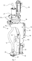
Figure 1 is a perspective view of a CNC machine operable pursuant to an additive manufacturing process in forming articles, incorporating the present invention; -
Figure 2 is an enlarged perspective view of the carriage and applicator assembly of the machine shown inFigure 1 ; -
Figure 3 is an enlarged perspective view of the lower segment of the applicator assembly shown inFigure 2 ; -
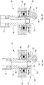
Figure 4a is an enlarged cross-sectional view of the material applicator head mounted on the lower end of the applicator assembly, illustrating the nozzle of a conduit for supplying a molten bead of thermoplastic material fully inserted into a passageway therethrough; -
Figure 4b is a view similar to the view ofFigure 4a , illustrating the nozzle thereof fully inserted into the passageway thereof; -
Figure 5 is a view similar to the view shown inFigure 4a , illustrating a bead of molten material being extruded by the applicator bead shown inFigure 4a onto a work surface, and a roller thereof engaging and compressing a portion of such bead against such work surface, forming a ply of an article being formed; -
Figure 6a is an enlarged perspective view of the lower end of the assembly shown inFigure 2 , provided with a roller formed with transversely spaced grooves; and -
Figure 6b is a view similar to the view shown inFigure 6a but with a roller formed with a transversely curved configuration. - Referring to
Figure 1 of the drawings, there is illustrated a programmable computer numeric control (CNC) machine embodying the present invention which includes abed 20 provided with a pair of transversely spacedside walls gantry 23 supported onside walls carriage 24 mounted ongantry 23, acarrier 25 mounted oncarriage 24 and anapplicator assembly 26 mounted oncarrier 25. Supported onbed 20 betweenside walls worktable 27 provided with a support surface disposed in an x-y plane, which may be fixed or displaceable along an x-axis. In the displaceable version, the worktable is displaceable along a set of rails mounted on the bed by means of servomotors mounted on the bed and operatively connected to the worktable. Gantry 23 is disposed along a y-axis, supported at the ends thereof onend walls guide rails side walls gantry 23 and is provided with asupport member 30 mounted on and displaceable along a set ofguide rails member 30.Carrier 25 is mounted on a set of spaced, vertically disposedguide rails - As best shown in
Figure 2 ,carrier 25 is provided with abase platform 36, agear box 37 fixedly mounted in the upper side thereof and amounting platform 38 rotatably mounted on the underside thereof, provided with openings therethrough disposed along the z-axis of the carrier. Such gear box is provided with a gear arrangement provided with an opening therethrough disposed coaxially with the aligned openings ingear box 37 andplatforms platform 38 for rotation about such x-axis, and rotatable about such axis by means of aservomotor 39 mounted onbase platform 36 and operatively connected to such gear arrangement. -
Applicator assembly 26 includes anupper segment 41 and alower segment 42.Segment 41 includes atransverse portion 41a secured to the underside ofmounting platform 38 for rotational movement about the z-axis, provided with an opening therethrough along such z-axis, and a dependingportion 41 disposed laterally relative to such axis.Segment 42 consisting of a housing disposed on an inner side of dependingsegment portion 41b, is mounted on a shaft journalled in a lower end ofportion 41b, intersecting and disposed perpendicular to the z-axis ofcarrier 25, and further is provided with a laterallyprojecting application head 43 at a free end thereof. Mounted on abracket 44 provided on an outer side ofsegment portion 41b is aservomotor 45 operatively connected to the shaft journalled inportion 41b for pivotally displacingsegment 42 in y-z plane. - Referring to
Figures 4a and 4b ,applicator head 43 includes ahousing 46 mounted on and projecting laterally from the lower end ofsegment 42, and abracket 47.Housing 46 is provided with acylindrical opening 48 therethrough provided with an enlarged portion, a roller bearing 49 mounted in such enlarged portion of such opening and acylindrical sleeve 50 disposed in such enlarged portion, mounted on the inner race of such bearing, having an inner diameter corresponding to opening 48 and including a portion extending beyondhousing 46. Housing opening 48 andsleeve 50 are configured to receive therein anozzle 51 of aflexible conduit 52 for conveying and extruding amolten bead 53 of a thermoplastic material through such nozzle provided with anoutput die 54 as shown inFigure 5 . -
Bracket 47 includes anannular base portion 55 coaxially mounted on the lower, exposed end ofsleeve 50 and rotatable withsleeve 50 about the axis thereof, anannular plate portion 56 coaxially mounted onannular base portion 55 and spaced axially relative to bearing 49, and asprocket 56a mounted onbase portion 55, coaxially on exposedportion 55. Bracket 47 further includes a pair of spaced dependingbrackets shaft 58 on which there is mounted arotatable roller 59. The axis of rotation ofshaft 58 is disposed along the line of intersection of a first plane disposed perpendicular to the axis ofpassageway 48 and a second plane disposed parallel to such axis. - As best shown in
Figure 3 ,bracket 47 is rotatably displaceable about the axis thereof by aservomotor 60 supported on an L-shaped bracket 61 mounted on a lower rear side oflower applicator segment 42, having anoutput shaft 62 projecting through an opening 63 inbracket 61, provided with asprocket 64 drivingly connected tosprocket 56 by means of abelt 65. -
Conduit 52 consists of an elongated, flexible material for conducting a molten bead of a thermoplastic material under pressure from a source disposed oncarrier 25 or another source, toapplicator head 43. An intermediate portion of such conduit is routed through the openings throughgear box 37,support platform 36 andmounting platform 38, along the z-axis ofcarrier 25. Such material is heated sufficiently to form a molten bead thereof, readily guide such bead throughconduit 52 and extrude it throughapplicator head 43 in forming a strata of plies fusing together in forming an article. Such material supplied through such conduit and extruded to form an article may be provided with fibers which facilitate and enhance the fusion of extruded, engaging plies. - In the use of the machine as described in forming an article pursuant to the additive manufacturing method, with the machine suitably programmed and activated, a bead of molten material would be extruded along a defined path either on
support surface 27 of the machine or previously extruder plies of such material, ahead of the path ofroller 59, and caused to be engaged and compressed by such roller either against such support surface of a previously applied heated ply of material, fusing such plies together to form an object consisting of a strata of material plies fused together forming either an end product or an oversized, near duplicate thereof. - In the course of forming such article, the control system of the machine, in executing the inputted program, would operate the several servomotors as described to displace the support surface or gantry along the x-axis, displace the carriage along the y-axis, displace the carrier along a z-axis, pivot
lower applicator segment 42 about an axis disposed in an x-y plane and rotatebracket 47 about a z-axis thereof, pursuant to the inputted program, to provide the described end product or an oversized, near duplicate thereof. - The bead engaging portion of
roller 59 may be cylindrical as shown inFigure 5 , serrated as shown inFigure 6a or curved along the length thereof as shown inFigure 6b . In circumstances where reinforcing fibers are provided in the molding material applied, it is preferred to utilize a roller with an irregular surface as shown inFigure 6a which is effective in causing outlying portions of such fibers to engage and penetrate heated adjacent plies, enhancing the fusion of such plies. - In the practice of the invention as described, an article may be formed simply by forming a strata of plies defining the intended final configuration of the article; forming a strata of plies defining an interim configuration minimally exceeding the intended final configuration and then machining such interim configuration to provide the final configuration thereof; providing a permanent substructure preferably of a metal, having a configuration smaller than the intended final configuration of the article, and forming a strata of plies on such substructure providing the intended final configuration of the article; providing a permanent substructure preferably of a metal, having a configuration smaller than the intended final configuration of the article, forming a strata of plies on such substructure in forming an interim configuration slightly greater than the intended final configuration and then machining such interim configuration to provide the intended final configuration; providing a mold having a configuration smaller than the intended final configuration of the article, forming a strata of plies on such mold slightly greater than the intended final configuration of the article, machining such interim configuration to provide the final configuration of the article and then removing such mold; and providing a mold having a configuration smaller than the intended final configuration of the article, forming a strata of plies on such mold slightly greater than the intended final configuration of the article, machining such interim configuration to provide the final configuration of the article and then removing such mold.
Claims (15)
- A programmable CNC machine comprising:a worktable (27) supported on a bed (20), having a support surface disposed in an x-y plane, disposed in one of a fixed condition on said bed and a displaceable condition, along the y-axis;a gantry (23) supported on said bed along an x-axis, disposed in one of a fixed condition on said bed with a worktable displaceable along the y-axis and a displaceable condition along the y-axis of said bed with said worktable disposed in a fixed condition;a carriage (24) mounted on said gantry, displaceable along the x-axis;a carrier (25) mounted on said carriage, displaceable along a z-axis;an applicator assembly (26) including an upper segment (41) depending from said carrier and rotationally connected to said carrier about said z-axis, and a lower segment (42) rotatably connected to said upper segment for pivotal movement relative to said upper segment about a pivotal axis intersecting said z-axis, wherein said lower segment includes an applicator head (43) at an end of the lower segment (42) having a cylindrical passageway therethrough, the lower segment being provided with an axis disposed in an x-z plane,a bracket (47) rotatable with a sleeve (50) mounted on a bearing (49) in the applicator head (43), the bracket being mounted on an underside of said lower segment, rotatable about the axis of said cylindrical passageway, and having a bracket passageway therethrough disposed coaxially with said cylindrical passageway;a conduit (52) for conducting a bead of molten thermoplastic material having an inlet connectable to a source of said material and an outlet inserted into said cylindrical passageway;a roller (59) depending from the lower segment and mounted to the bracket (47), the roller being rotatable about an axis of rotation disposed along the line of intersection of a first plane disposed perpendicular to said cylindrical passageway and a second plane disposed parallel to said cylindrical passageway;a plurality of servomotors each operatively connected to one of said aforementioned moveable components for selectively displacing said component one of rotationally or linearly; anda computer functional pursuant to the execution of an inputted program for operatively controlling said servomotors.
- The machine according to claim 1, including means disposed on said carrier for holding a supply of a heated thermoplastic material and wherein said conduit (52) is formed of a flexible material having an inlet for receiving a bead of said material from said holding means, wherein the conduit includes an intermediate portion extending through passageways provided in said carrier (25) and upper segment (41) of said applicator assembly (26) and an outlet received into and through said bracket passageway for depositing a molten bead of said thermoplastic material onto a surface, wherein the outlet of the conduit is disposed ahead of a line of travel of said roller (59).
- The machine of claim 2, wherein the outlet of the conduit (52) is configured to deposit at least a portion of said bead of material on one of a work surface (27) or a previously deposited bead of material ahead of said roller (59) which upon advancement thereof is configured to engage and compress the at least a portion of said bead of material against the one of the work surface or the previously deposited bead of material.
- The machine of claim 3, wherein a surface of the bead-engaging portion of said roller (59) is formed of a configuration functional upon pressing engagement with said molten bead of thermoplastic material extended through said bracket to enhance joining of mating plies of said extruded material.
- The machine of claim 4, wherein the bead-engaging portion of said roller (59) includes a plurality of spaced, annular groves disposed concentric with the axis of rotation of said roller.
- The machine of claim 4, wherein the bead-engaging portion of said roller (59) includes a transversely curved configuration.
- The machine of claim 4, wherein the surface of the bead-engaging portion of said roller (9) is configured to, upon pressing engagement of a bead of molten material extruded through said bracket, compress and cause an exposed portion of reinforcing fibers interspersed in said material to engage and become entrained in adjoining bead portions, improving the adhesion of the adjoining bead portions.
- The machine of claim 1, wherein said bearing (49) includes an outer race mounted on said lower segment (42) of said applicator assembly (26) concentrically with the axis of said cylindrical passageway and an inner race connected to said bracket (47).
- The machine of claim 1, wherein the axis of rotation of said roller (59) is spaced from a longitudinal axis of said cylindrical passageway a distance sufficient to allow the bead of said material extruded through said cylindrical passageway onto the support surface or a previously applied ply of said material to be engaged and compressed by the roller.
- The machine of claim 1, further including a gear box (37) mounted on said carrier (25) and drivingly connected to said upper segment (41) of said applicator assembly (26).
- The machine of claim 10, wherein said gear box, a portion of said carrier supporting said gear box (37), and said upper segment (41) of said applicator assembly (26) are provided with a set of aligned passageways therethrough, and wherein said conduit extends through the aligned passageways.
- A method of forming an article on a work surface (27) using the CNC machine according to any of the claims 1-11 and comprising:applying, with the applicator assembly (26), a bead of molten thermoplastic material on said work surface along a selected path including at least one ply functional to produce an object of a prescribed configuration, wherein said material is applied in plies,guiding the roller (59) mounted to the bracket (47) over applied plies of said material in compressing relation to merge engaging plies together, the bracket (47) being rotatable with the sleeve (50) mounted on the bearing (49) in the applicator head;wherein said material is applied along said selected path ahead of said roller.
- The method of claim 12, wherein guiding said roller (59) over applied plies of said material includes integrating reinforcing fibers in said material.
- The method of claim 12, wherein said roller (59) includes a ply engaging surface, and wherein said ply engaging surface is transversely curved or said ply engaging surface includes a plurality of axially spaced circular grooves.
- The method of claim 12, further including providing a substructure of said object in a diminished, approximate facsimile of an intended configuration of said object, and applying said material on said substructure in a configuration exceeding said intended configuration of said object, and removing a portion of said material exceeding said intended final configuration of said object.
Applications Claiming Priority (2)
| Application Number | Priority Date | Filing Date | Title |
|---|---|---|---|
| US14/980,818 US10611073B2 (en) | 2015-12-28 | 2015-12-28 | Machine and method for forming articles |
| PCT/US2016/044159 WO2017116507A1 (en) | 2015-12-28 | 2016-07-27 | Machine and method for forming articles |
Publications (2)
| Publication Number | Publication Date |
|---|---|
| EP3397457A1 EP3397457A1 (en) | 2018-11-07 |
| EP3397457B1 true EP3397457B1 (en) | 2021-03-24 |
Family
ID=56787671
Family Applications (1)
| Application Number | Title | Priority Date | Filing Date |
|---|---|---|---|
| EP16754581.3A Active EP3397457B1 (en) | 2015-12-28 | 2016-07-27 | Machine and method for forming articles |
Country Status (4)
| Country | Link |
|---|---|
| US (7) | US10611073B2 (en) |
| EP (1) | EP3397457B1 (en) |
| CA (1) | CA3002964C (en) |
| WO (1) | WO2017116507A1 (en) |
Families Citing this family (12)
| Publication number | Priority date | Publication date | Assignee | Title |
|---|---|---|---|---|
| EP3218160A4 (en) * | 2014-11-14 | 2018-10-17 | Nielsen-Cole, Cole | Additive manufacturing techniques and systems to form composite materials |
| US10071525B2 (en) * | 2017-02-07 | 2018-09-11 | Thermwood Corporation | Apparatus and method for printing long composite thermoplastic parts on a dual gantry machine during additive manufacturing |
| US10875244B2 (en) | 2017-05-17 | 2020-12-29 | Slice Engineering LLC | Adaptable high-performance extrusion head for fused filament fabrication systems |
| US10786946B2 (en) * | 2017-09-13 | 2020-09-29 | Thermwood Corporation | Apparatus and methods for compressing material during additive manufacturing |
| US10933586B2 (en) | 2017-09-13 | 2021-03-02 | Thermwood Corporation | Apparatus and method for printing large thermoplastic parts during additive manufacturing |
| US10245788B1 (en) * | 2018-02-14 | 2019-04-02 | Thermwood Corporation | Methods and apparatus for thermal compensation during additive manufacturing |
| US11383437B2 (en) * | 2018-10-02 | 2022-07-12 | Dongming Hu | Hybrid manufacturing apparatus |
| US10786944B1 (en) | 2019-11-22 | 2020-09-29 | Thermwood Corporation | Near net shape additive manufacturing |
| CN111497225A (en) * | 2020-04-03 | 2020-08-07 | 江南大学 | Spray head, printer and printing method suitable for continuous fiber reinforced composite material |
| US11577468B2 (en) * | 2020-04-03 | 2023-02-14 | Korea Institute Of Energy Research | 3-D printing apparatus for fabricating supercapacitor or secondary battery |
| USD980882S1 (en) * | 2020-12-31 | 2023-03-14 | Slice Engineering, Llc | 3D printer hotend |
| US11618209B1 (en) | 2022-03-24 | 2023-04-04 | Thermwood Corporation | Apparatus and method for depositing material during additive manufacturing |
Family Cites Families (34)
| Publication number | Priority date | Publication date | Assignee | Title |
|---|---|---|---|---|
| US4588872A (en) | 1984-03-22 | 1986-05-13 | Bollinger John G | Self-guided welding machine |
| US4909880A (en) * | 1988-05-17 | 1990-03-20 | General Dynamics Corporation | Method and apparatus for tape winding on irregular shapes |
| US5700347A (en) * | 1996-01-11 | 1997-12-23 | The Boeing Company | Thermoplastic multi-tape application head |
| US6004124A (en) * | 1998-01-26 | 1999-12-21 | Stratasys, Inc. | Thin-wall tube liquifier |
| US20050104241A1 (en) | 2000-01-18 | 2005-05-19 | Objet Geometried Ltd. | Apparatus and method for three dimensional model printing |
| US7153454B2 (en) * | 2003-01-21 | 2006-12-26 | University Of Southern California | Multi-nozzle assembly for extrusion of wall |
| US6932547B2 (en) * | 2003-12-24 | 2005-08-23 | Thermwood Corporation | Toolhead assembly for CNC machines having misalignment prevention means |
| EP1757433B1 (en) * | 2005-08-25 | 2009-12-30 | Ingersoll Machine Tools, Inc. | Compact fiber placement apparatus |
| US7628882B2 (en) | 2005-08-25 | 2009-12-08 | Ingersoll Machine Tools, Inc. | Add roller for a fiber placement machine |
| US7810539B2 (en) | 2005-08-25 | 2010-10-12 | Ingersoll Machine Tools, Inc. | Compaction roller for a fiber placement machine |
| US7731816B2 (en) | 2006-02-16 | 2010-06-08 | Ingersoll Machine Tools, Inc. | System and method for heating carbon fiber using infrared radiation in a fiber placement machine |
| US7841375B2 (en) | 2006-07-10 | 2010-11-30 | Ingersoll Machine Tools, Inc. | Tow catch for fiber placement head |
| US20100206224A1 (en) | 2007-09-24 | 2010-08-19 | Berner Fachhochschule fur Technik und informatik HTI | Device for the deposition of layers |
| WO2009052263A1 (en) | 2007-10-16 | 2009-04-23 | Ingersoll Machine Tools, Inc. | Fiber placement machine platform system having interchangeable head and creel assemblies |
| EP2349976B1 (en) | 2008-08-25 | 2012-12-26 | Jubilant Life Sciences Limited | A process for producing (s)-3-[(1-dimethylamino)ethyl]phenyl-n-ethyl-n-methyl-carbamate via novel intermediates |
| US20100200168A1 (en) | 2009-02-06 | 2010-08-12 | Ingersoll Machine Tools, Inc. | Fiber delivery apparatus and system having a creel and fiber placement head sans fiber redirect |
| CN101817121B (en) * | 2010-04-15 | 2012-03-28 | 华中科技大学 | Deposition forming composite manufacturing method of part and mould and auxiliary device thereof |
| US8954180B2 (en) | 2010-08-06 | 2015-02-10 | Ingersoll Machine Tools, Inc. | Manufacturing process and apparatus having an interchangeable machine tool head with integrated control |
| US8534338B2 (en) | 2010-10-15 | 2013-09-17 | Ingersoll Machine Tools, Inc. | Fiber delivery apparatus and system having a creel and fiber placement head with polar axis of rotation |
| US8613302B2 (en) * | 2011-03-02 | 2013-12-24 | Fives Machining Systems, Inc. | Reversing fiber placement head |
| GB201118807D0 (en) | 2011-11-01 | 2011-12-14 | Univ Loughborough | Method and apparatus |
| US8684720B2 (en) * | 2011-12-05 | 2014-04-01 | Fives Machining Systems, Inc. | Fiber delivery system for composite part manufacture |
| US9186848B2 (en) | 2013-03-22 | 2015-11-17 | Markforged, Inc. | Three dimensional printing of composite reinforced structures |
| US9156205B2 (en) * | 2013-03-22 | 2015-10-13 | Markforged, Inc. | Three dimensional printer with composite filament fabrication |
| US9751260B2 (en) * | 2013-07-24 | 2017-09-05 | The Boeing Company | Additive-manufacturing systems, apparatuses and methods |
| EP3845365A1 (en) * | 2013-10-30 | 2021-07-07 | Branch Technology, Inc. | Additive manufacturing of buildings and other structures |
| US20150174824A1 (en) * | 2013-12-19 | 2015-06-25 | Karl Joseph Gifford | Systems and methods for 3D printing with multiple exchangeable printheads |
| US9550319B2 (en) * | 2014-02-07 | 2017-01-24 | The Boeing Company | Extrusion apparatus and method |
| US9796140B2 (en) * | 2014-06-19 | 2017-10-24 | Autodesk, Inc. | Automated systems for composite part fabrication |
| US10780628B2 (en) * | 2014-07-18 | 2020-09-22 | Fusion3 Design LLC | Apparatus and method for fabricating three-dimensional objects |
| WO2016014543A1 (en) * | 2014-07-22 | 2016-01-28 | Stratasys, Inc. | Gear-based liquefier assembly for additive manufacturing system, and methods of use thereof |
| US10201941B2 (en) * | 2015-07-31 | 2019-02-12 | The Boeing Company | Systems for additively manufacturing composite parts |
| US10166752B2 (en) * | 2015-07-31 | 2019-01-01 | The Boeing Company | Methods for additively manufacturing composite parts |
| US20180050502A1 (en) | 2016-08-19 | 2018-02-22 | Ingersoll Machine Tools, Inc. | Fiber placement head with secondary compaction arrangement |
-
2015
- 2015-12-28 US US14/980,818 patent/US10611073B2/en active Active
-
2016
- 2016-07-27 CA CA3002964A patent/CA3002964C/en active Active
- 2016-07-27 WO PCT/US2016/044159 patent/WO2017116507A1/en active Application Filing
- 2016-07-27 EP EP16754581.3A patent/EP3397457B1/en active Active
-
2018
- 2018-04-11 US US15/950,778 patent/US10286588B2/en active Active
-
2019
- 2019-05-03 US US16/403,079 patent/US10668657B2/en active Active
-
2020
- 2020-04-29 US US16/861,490 patent/US11014279B2/en active Active
-
2021
- 2021-05-17 US US17/322,540 patent/US11491696B2/en active Active
-
2022
- 2022-10-07 US US18/045,048 patent/US11865760B2/en active Active
-
2023
- 2023-12-05 US US18/529,979 patent/US20240123669A1/en active Pending
Non-Patent Citations (1)
| Title |
|---|
| None * |
Also Published As
| Publication number | Publication date |
|---|---|
| US11014279B2 (en) | 2021-05-25 |
| CA3002964C (en) | 2021-06-01 |
| US10286588B2 (en) | 2019-05-14 |
| US20180229416A1 (en) | 2018-08-16 |
| US20170182698A1 (en) | 2017-06-29 |
| US11865760B2 (en) | 2024-01-09 |
| US20230056184A1 (en) | 2023-02-23 |
| US10668657B2 (en) | 2020-06-02 |
| US10611073B2 (en) | 2020-04-07 |
| US11491696B2 (en) | 2022-11-08 |
| EP3397457A1 (en) | 2018-11-07 |
| US20210268709A1 (en) | 2021-09-02 |
| CA3002964A1 (en) | 2017-07-06 |
| US20190255752A1 (en) | 2019-08-22 |
| US20240123669A1 (en) | 2024-04-18 |
| US20200254674A1 (en) | 2020-08-13 |
| WO2017116507A1 (en) | 2017-07-06 |
Similar Documents
| Publication | Publication Date | Title |
|---|---|---|
| EP3397457B1 (en) | Machine and method for forming articles | |
| EP3580041B1 (en) | Apparatus and method for printing long composite thermoplastic parts on a dual gantry machine during additive manufacturing | |
| US10940681B2 (en) | Apparatus and methods for fabricating components | |
| CA3009092C (en) | Device and method for producing a three-dimensional article with a fibre feed device | |
| US20200130257A1 (en) | Apparatus and Process for Forming Three-Dimensional Objects | |
| US10549477B2 (en) | Methods and apparatus for controlling an applicator head during additive manufacturing | |
| KR101575061B1 (en) | Apparatus for changing nozzle of 3D printer | |
| EP3439855B1 (en) | Methods of securing an initial layer during additive manufacturing of thermoplastic material | |
| EP4140695A1 (en) | A method and a mold for forming a marine article | |
| JP2023514603A (en) | Method and system for manufacturing boat molds by additive manufacturing | |
| IT201800010225A1 (en) | Improved equipment and method for 3D printing articles with high mechanical and aesthetic characteristics. | |
| US20230302721A1 (en) | Apparatus and method for depositing material during additive manufacturing |
Legal Events
| Date | Code | Title | Description |
|---|---|---|---|
| STAA | Information on the status of an ep patent application or granted ep patent |
Free format text: STATUS: THE INTERNATIONAL PUBLICATION HAS BEEN MADE |
|
| PUAI | Public reference made under article 153(3) epc to a published international application that has entered the european phase |
Free format text: ORIGINAL CODE: 0009012 |
|
| STAA | Information on the status of an ep patent application or granted ep patent |
Free format text: STATUS: REQUEST FOR EXAMINATION WAS MADE |
|
| 17P | Request for examination filed |
Effective date: 20180727 |
|
| AK | Designated contracting states |
Kind code of ref document: A1 Designated state(s): AL AT BE BG CH CY CZ DE DK EE ES FI FR GB GR HR HU IE IS IT LI LT LU LV MC MK MT NL NO PL PT RO RS SE SI SK SM TR |
|
| AX | Request for extension of the european patent |
Extension state: BA ME |
|
| RIN1 | Information on inventor provided before grant (corrected) |
Inventor name: SUSNJARA, KENNETH, J. |
|
| DAV | Request for validation of the european patent (deleted) | ||
| DAX | Request for extension of the european patent (deleted) | ||
| STAA | Information on the status of an ep patent application or granted ep patent |
Free format text: STATUS: EXAMINATION IS IN PROGRESS |
|
| 17Q | First examination report despatched |
Effective date: 20191125 |
|
| REG | Reference to a national code |
Ref country code: DE Ref legal event code: R079 Ref document number: 602016054844 Country of ref document: DE Free format text: PREVIOUS MAIN CLASS: B29C0067000000 Ipc: B29C0064236000 |
|
| RIC1 | Information provided on ipc code assigned before grant |
Ipc: B29C 64/209 20170101ALI20200924BHEP Ipc: B29C 64/188 20170101ALI20200924BHEP Ipc: B29C 64/106 20170101AFI20200924BHEP Ipc: B29C 64/236 20170101ALI20200924BHEP |
|
| GRAP | Despatch of communication of intention to grant a patent |
Free format text: ORIGINAL CODE: EPIDOSNIGR1 |
|
| STAA | Information on the status of an ep patent application or granted ep patent |
Free format text: STATUS: GRANT OF PATENT IS INTENDED |
|
| INTG | Intention to grant announced |
Effective date: 20201104 |
|
| RIC1 | Information provided on ipc code assigned before grant |
Ipc: B29C 64/106 20170101ALI20201023BHEP Ipc: B33Y 10/00 20150101ALI20201023BHEP Ipc: B29C 64/236 20170101AFI20201023BHEP Ipc: B33Y 30/00 20150101ALI20201023BHEP |
|
| GRAS | Grant fee paid |
Free format text: ORIGINAL CODE: EPIDOSNIGR3 |
|
| GRAA | (expected) grant |
Free format text: ORIGINAL CODE: 0009210 |
|
| STAA | Information on the status of an ep patent application or granted ep patent |
Free format text: STATUS: THE PATENT HAS BEEN GRANTED |
|
| AK | Designated contracting states |
Kind code of ref document: B1 Designated state(s): AL AT BE BG CH CY CZ DE DK EE ES FI FR GB GR HR HU IE IS IT LI LT LU LV MC MK MT NL NO PL PT RO RS SE SI SK SM TR |
|
| REG | Reference to a national code |
Ref country code: GB Ref legal event code: FG4D |
|
| REG | Reference to a national code |
Ref country code: CH Ref legal event code: EP |
|
| REG | Reference to a national code |
Ref country code: IE Ref legal event code: FG4D |
|
| REG | Reference to a national code |
Ref country code: AT Ref legal event code: REF Ref document number: 1374052 Country of ref document: AT Kind code of ref document: T Effective date: 20210415 Ref country code: DE Ref legal event code: R096 Ref document number: 602016054844 Country of ref document: DE |
|
| REG | Reference to a national code |
Ref country code: NL Ref legal event code: FP |
|
| REG | Reference to a national code |
Ref country code: LT Ref legal event code: MG9D |
|
| PG25 | Lapsed in a contracting state [announced via postgrant information from national office to epo] |
Ref country code: BG Free format text: LAPSE BECAUSE OF FAILURE TO SUBMIT A TRANSLATION OF THE DESCRIPTION OR TO PAY THE FEE WITHIN THE PRESCRIBED TIME-LIMIT Effective date: 20210624 Ref country code: NO Free format text: LAPSE BECAUSE OF FAILURE TO SUBMIT A TRANSLATION OF THE DESCRIPTION OR TO PAY THE FEE WITHIN THE PRESCRIBED TIME-LIMIT Effective date: 20210624 Ref country code: GR Free format text: LAPSE BECAUSE OF FAILURE TO SUBMIT A TRANSLATION OF THE DESCRIPTION OR TO PAY THE FEE WITHIN THE PRESCRIBED TIME-LIMIT Effective date: 20210625 Ref country code: HR Free format text: LAPSE BECAUSE OF FAILURE TO SUBMIT A TRANSLATION OF THE DESCRIPTION OR TO PAY THE FEE WITHIN THE PRESCRIBED TIME-LIMIT Effective date: 20210324 Ref country code: FI Free format text: LAPSE BECAUSE OF FAILURE TO SUBMIT A TRANSLATION OF THE DESCRIPTION OR TO PAY THE FEE WITHIN THE PRESCRIBED TIME-LIMIT Effective date: 20210324 |
|
| PG25 | Lapsed in a contracting state [announced via postgrant information from national office to epo] |
Ref country code: SE Free format text: LAPSE BECAUSE OF FAILURE TO SUBMIT A TRANSLATION OF THE DESCRIPTION OR TO PAY THE FEE WITHIN THE PRESCRIBED TIME-LIMIT Effective date: 20210324 Ref country code: RS Free format text: LAPSE BECAUSE OF FAILURE TO SUBMIT A TRANSLATION OF THE DESCRIPTION OR TO PAY THE FEE WITHIN THE PRESCRIBED TIME-LIMIT Effective date: 20210324 Ref country code: LV Free format text: LAPSE BECAUSE OF FAILURE TO SUBMIT A TRANSLATION OF THE DESCRIPTION OR TO PAY THE FEE WITHIN THE PRESCRIBED TIME-LIMIT Effective date: 20210324 |
|
| REG | Reference to a national code |
Ref country code: AT Ref legal event code: MK05 Ref document number: 1374052 Country of ref document: AT Kind code of ref document: T Effective date: 20210324 |
|
| PG25 | Lapsed in a contracting state [announced via postgrant information from national office to epo] |
Ref country code: AT Free format text: LAPSE BECAUSE OF FAILURE TO SUBMIT A TRANSLATION OF THE DESCRIPTION OR TO PAY THE FEE WITHIN THE PRESCRIBED TIME-LIMIT Effective date: 20210324 Ref country code: SM Free format text: LAPSE BECAUSE OF FAILURE TO SUBMIT A TRANSLATION OF THE DESCRIPTION OR TO PAY THE FEE WITHIN THE PRESCRIBED TIME-LIMIT Effective date: 20210324 Ref country code: EE Free format text: LAPSE BECAUSE OF FAILURE TO SUBMIT A TRANSLATION OF THE DESCRIPTION OR TO PAY THE FEE WITHIN THE PRESCRIBED TIME-LIMIT Effective date: 20210324 Ref country code: CZ Free format text: LAPSE BECAUSE OF FAILURE TO SUBMIT A TRANSLATION OF THE DESCRIPTION OR TO PAY THE FEE WITHIN THE PRESCRIBED TIME-LIMIT Effective date: 20210324 Ref country code: LT Free format text: LAPSE BECAUSE OF FAILURE TO SUBMIT A TRANSLATION OF THE DESCRIPTION OR TO PAY THE FEE WITHIN THE PRESCRIBED TIME-LIMIT Effective date: 20210324 |
|
| PG25 | Lapsed in a contracting state [announced via postgrant information from national office to epo] |
Ref country code: PL Free format text: LAPSE BECAUSE OF FAILURE TO SUBMIT A TRANSLATION OF THE DESCRIPTION OR TO PAY THE FEE WITHIN THE PRESCRIBED TIME-LIMIT Effective date: 20210324 Ref country code: PT Free format text: LAPSE BECAUSE OF FAILURE TO SUBMIT A TRANSLATION OF THE DESCRIPTION OR TO PAY THE FEE WITHIN THE PRESCRIBED TIME-LIMIT Effective date: 20210726 Ref country code: RO Free format text: LAPSE BECAUSE OF FAILURE TO SUBMIT A TRANSLATION OF THE DESCRIPTION OR TO PAY THE FEE WITHIN THE PRESCRIBED TIME-LIMIT Effective date: 20210324 Ref country code: SK Free format text: LAPSE BECAUSE OF FAILURE TO SUBMIT A TRANSLATION OF THE DESCRIPTION OR TO PAY THE FEE WITHIN THE PRESCRIBED TIME-LIMIT Effective date: 20210324 Ref country code: IS Free format text: LAPSE BECAUSE OF FAILURE TO SUBMIT A TRANSLATION OF THE DESCRIPTION OR TO PAY THE FEE WITHIN THE PRESCRIBED TIME-LIMIT Effective date: 20210724 |
|
| REG | Reference to a national code |
Ref country code: DE Ref legal event code: R097 Ref document number: 602016054844 Country of ref document: DE |
|
| PG25 | Lapsed in a contracting state [announced via postgrant information from national office to epo] |
Ref country code: AL Free format text: LAPSE BECAUSE OF FAILURE TO SUBMIT A TRANSLATION OF THE DESCRIPTION OR TO PAY THE FEE WITHIN THE PRESCRIBED TIME-LIMIT Effective date: 20210324 Ref country code: ES Free format text: LAPSE BECAUSE OF FAILURE TO SUBMIT A TRANSLATION OF THE DESCRIPTION OR TO PAY THE FEE WITHIN THE PRESCRIBED TIME-LIMIT Effective date: 20210324 Ref country code: DK Free format text: LAPSE BECAUSE OF FAILURE TO SUBMIT A TRANSLATION OF THE DESCRIPTION OR TO PAY THE FEE WITHIN THE PRESCRIBED TIME-LIMIT Effective date: 20210324 |
|
| PLBE | No opposition filed within time limit |
Free format text: ORIGINAL CODE: 0009261 |
|
| STAA | Information on the status of an ep patent application or granted ep patent |
Free format text: STATUS: NO OPPOSITION FILED WITHIN TIME LIMIT |
|
| PG25 | Lapsed in a contracting state [announced via postgrant information from national office to epo] |
Ref country code: SI Free format text: LAPSE BECAUSE OF FAILURE TO SUBMIT A TRANSLATION OF THE DESCRIPTION OR TO PAY THE FEE WITHIN THE PRESCRIBED TIME-LIMIT Effective date: 20210324 |
|
| REG | Reference to a national code |
Ref country code: CH Ref legal event code: PL |
|
| 26N | No opposition filed |
Effective date: 20220104 |
|
| PG25 | Lapsed in a contracting state [announced via postgrant information from national office to epo] |
Ref country code: MC Free format text: LAPSE BECAUSE OF FAILURE TO SUBMIT A TRANSLATION OF THE DESCRIPTION OR TO PAY THE FEE WITHIN THE PRESCRIBED TIME-LIMIT Effective date: 20210324 |
|
| REG | Reference to a national code |
Ref country code: BE Ref legal event code: MM Effective date: 20210731 |
|
| PG25 | Lapsed in a contracting state [announced via postgrant information from national office to epo] |
Ref country code: LI Free format text: LAPSE BECAUSE OF NON-PAYMENT OF DUE FEES Effective date: 20210731 Ref country code: CH Free format text: LAPSE BECAUSE OF NON-PAYMENT OF DUE FEES Effective date: 20210731 |
|
| PG25 | Lapsed in a contracting state [announced via postgrant information from national office to epo] |
Ref country code: IS Free format text: LAPSE BECAUSE OF FAILURE TO SUBMIT A TRANSLATION OF THE DESCRIPTION OR TO PAY THE FEE WITHIN THE PRESCRIBED TIME-LIMIT Effective date: 20210724 Ref country code: LU Free format text: LAPSE BECAUSE OF NON-PAYMENT OF DUE FEES Effective date: 20210727 |
|
| PG25 | Lapsed in a contracting state [announced via postgrant information from national office to epo] |
Ref country code: BE Free format text: LAPSE BECAUSE OF NON-PAYMENT OF DUE FEES Effective date: 20210731 |
|
| REG | Reference to a national code |
Ref country code: DE Ref legal event code: R082 Ref document number: 602016054844 Country of ref document: DE Representative=s name: CBDL PATENTANWAELTE GBR, DE |
|
| P01 | Opt-out of the competence of the unified patent court (upc) registered |
Effective date: 20230523 |
|
| PG25 | Lapsed in a contracting state [announced via postgrant information from national office to epo] |
Ref country code: CY Free format text: LAPSE BECAUSE OF FAILURE TO SUBMIT A TRANSLATION OF THE DESCRIPTION OR TO PAY THE FEE WITHIN THE PRESCRIBED TIME-LIMIT Effective date: 20210324 |
|
| PG25 | Lapsed in a contracting state [announced via postgrant information from national office to epo] |
Ref country code: HU Free format text: LAPSE BECAUSE OF FAILURE TO SUBMIT A TRANSLATION OF THE DESCRIPTION OR TO PAY THE FEE WITHIN THE PRESCRIBED TIME-LIMIT; INVALID AB INITIO Effective date: 20160727 |
|
| PGFP | Annual fee paid to national office [announced via postgrant information from national office to epo] |
Ref country code: NL Payment date: 20230719 Year of fee payment: 8 |
|
| PGFP | Annual fee paid to national office [announced via postgrant information from national office to epo] |
Ref country code: TR Payment date: 20230724 Year of fee payment: 8 Ref country code: IT Payment date: 20230724 Year of fee payment: 8 Ref country code: IE Payment date: 20230719 Year of fee payment: 8 Ref country code: GB Payment date: 20230721 Year of fee payment: 8 |
|
| PGFP | Annual fee paid to national office [announced via postgrant information from national office to epo] |
Ref country code: FR Payment date: 20230726 Year of fee payment: 8 Ref country code: DE Payment date: 20230719 Year of fee payment: 8 |