US11864330B2 - Thermally isolating mounting boss - Google Patents
Thermally isolating mounting boss Download PDFInfo
- Publication number
- US11864330B2 US11864330B2 US17/378,971 US202117378971A US11864330B2 US 11864330 B2 US11864330 B2 US 11864330B2 US 202117378971 A US202117378971 A US 202117378971A US 11864330 B2 US11864330 B2 US 11864330B2
- Authority
- US
- United States
- Prior art keywords
- pcb
- section
- pillars
- chassis
- base section
- Prior art date
- Legal status (The legal status is an assumption and is not a legal conclusion. Google has not performed a legal analysis and makes no representation as to the accuracy of the status listed.)
- Active, expires
Links
- 238000002955 isolation Methods 0.000 claims abstract description 26
- 230000008878 coupling Effects 0.000 claims abstract description 5
- 238000010168 coupling process Methods 0.000 claims abstract description 5
- 238000005859 coupling reaction Methods 0.000 claims abstract description 5
- 239000000463 material Substances 0.000 claims description 9
- 239000012212 insulator Substances 0.000 claims description 6
- 150000003071 polychlorinated biphenyls Chemical class 0.000 description 32
- QHZSDTDMQZPUKC-UHFFFAOYSA-N 3,5-dichlorobiphenyl Chemical compound ClC1=CC(Cl)=CC(C=2C=CC=CC=2)=C1 QHZSDTDMQZPUKC-UHFFFAOYSA-N 0.000 description 28
- 239000011810 insulating material Substances 0.000 description 8
- 238000012546 transfer Methods 0.000 description 5
- 238000000034 method Methods 0.000 description 4
- 230000008569 process Effects 0.000 description 4
- 238000004891 communication Methods 0.000 description 3
- 239000002184 metal Substances 0.000 description 3
- 229910052751 metal Inorganic materials 0.000 description 3
- 238000012545 processing Methods 0.000 description 3
- 241001634884 Cochlicopa lubricella Species 0.000 description 2
- 230000008901 benefit Effects 0.000 description 2
- 238000013500 data storage Methods 0.000 description 2
- 230000000694 effects Effects 0.000 description 2
- 230000006872 improvement Effects 0.000 description 2
- 230000009467 reduction Effects 0.000 description 2
- 238000005266 casting Methods 0.000 description 1
- 239000004020 conductor Substances 0.000 description 1
- 238000005516 engineering process Methods 0.000 description 1
- 238000009413 insulation Methods 0.000 description 1
- 238000003754 machining Methods 0.000 description 1
- 150000002739 metals Chemical class 0.000 description 1
- 238000012986 modification Methods 0.000 description 1
- 230000004048 modification Effects 0.000 description 1
- 230000006855 networking Effects 0.000 description 1
- 239000007787 solid Substances 0.000 description 1
- 238000012360 testing method Methods 0.000 description 1
Images


Classifications
-
- H—ELECTRICITY
- H05—ELECTRIC TECHNIQUES NOT OTHERWISE PROVIDED FOR
- H05K—PRINTED CIRCUITS; CASINGS OR CONSTRUCTIONAL DETAILS OF ELECTRIC APPARATUS; MANUFACTURE OF ASSEMBLAGES OF ELECTRICAL COMPONENTS
- H05K7/00—Constructional details common to different types of electric apparatus
- H05K7/14—Mounting supporting structure in casing or on frame or rack
- H05K7/1417—Mounting supporting structure in casing or on frame or rack having securing means for mounting boards, plates or wiring boards
- H05K7/142—Spacers not being card guides
-
- H—ELECTRICITY
- H05—ELECTRIC TECHNIQUES NOT OTHERWISE PROVIDED FOR
- H05K—PRINTED CIRCUITS; CASINGS OR CONSTRUCTIONAL DETAILS OF ELECTRIC APPARATUS; MANUFACTURE OF ASSEMBLAGES OF ELECTRICAL COMPONENTS
- H05K5/00—Casings, cabinets or drawers for electric apparatus
- H05K5/0026—Casings, cabinets or drawers for electric apparatus provided with connectors and printed circuit boards [PCB], e.g. automotive electronic control units
-
- G—PHYSICS
- G06—COMPUTING; CALCULATING OR COUNTING
- G06F—ELECTRIC DIGITAL DATA PROCESSING
- G06F1/00—Details not covered by groups G06F3/00 - G06F13/00 and G06F21/00
- G06F1/16—Constructional details or arrangements
- G06F1/18—Packaging or power distribution
- G06F1/183—Internal mounting support structures, e.g. for printed circuit boards, internal connecting means
- G06F1/184—Mounting of motherboards
Definitions
- This disclosure relates generally to information handling systems and, more particularly, to thermally insulated mounting bosses.
- An information handling system generally processes, compiles, stores, and/or communicates information or data for business, personal, or other purposes thereby allowing users to take advantage of the value of the information.
- information handling systems may also vary regarding what information is handled, how the information is handled, how much information is processed, stored, or communicated, and how quickly and efficiently the information may be processed, stored, or communicated.
- the variations in information handling systems allow for information handling systems to be general or configured for a specific user or specific use such as financial transaction processing, airline reservations, enterprise data storage, or global communications.
- information handling systems may include a variety of hardware and software components that may be configured to process, store, and communicate information and may include one or more computer systems, data storage systems, and networking systems.
- PCB printed circuit board
- Embodiments disclosed herein may be generally directed to portable information handling systems and metal mounting bosses that provide structural support for a mainboard and provide a circuit for grounding the mainboard while reducing the amount of heat conducted through the mounting boss to the chassis.
- Embodiments disclosed herein may be directed to thermally insulated mounting bosses for portable information handling system.
- a thermally isolating mounting boss may comprise a base section having a base surface for coupling to a cover forming part of the chassis and an isolation section comprising a plurality of pillars, each pillar having a board contact surface for contacting a printed circuit board (PCB) and a cross-section area.
- a combined cross-section area of the plurality of pillars is less than a cross-section area of the base section.
- the base section may have a a cross-section dimension sized for a central bore.
- a connector may have a shaft configured for extending through the PCB and engaging the central bore and a cap for contact with a second side of the PCB.
- the plurality of pillars are positioned radially outward of the base section. In some embodiments, the plurality of pillars are formed separately from the base section.
- the plurality of pillars extend from the base section. In some embodiments, the plurality of pillars and the base section form a continuous structure. In some embodiments, the isolation section comprises a plurality of pillars connected by a plurality of transverse segments.
- a thermally isolating mounting boss may have a thermal insulator for positioning between the base section and a first side of the PCB, wherein a thickness of the thermal insulator and a height of the base section are approximately equal to a height of the plurality of pillars.
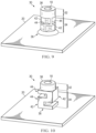
- FIG. 1 is a perspective view of a common mounting boss
- FIG. 2 is a cutaway perspective view of a portable chassis, illustrating positioning of a common mounting boss for supporting a PCB;
- FIG. 3 is a cutaway view of a common mounting boss, illustrating two paths for heat conduction from a PCB to a chassis;
- FIG. 4 is a cutaway view of a common mounting boss with a thermal insulator, illustrating a path for heat conduction from a PCB to a chassis;
- FIG. 5 is an image of a simulated temperature profile for a chassis using a common mounting boss to separate a PCB from a chassis;
- FIG. 6 is a cutaway view of one embodiment of a thermally isolating mounting boss with a thermal insulator
- FIG. 7 is an image of a simulated temperature profile for a chassis using one embodiment of a thermally isolating mounting boss to separate a PCB from a chassis;
- FIGS. 8 - 12 are perspective views of embodiments of a thermally isolating mounting boss.
- FIG. 13 is an image of a simulated temperature profile for a chassis using one embodiment of a thermally isolating mounting boss with isolating pillars to separate a PCB from a chassis.
- mounting boss “ 182 - 1 ” refers to an instance of a mounting boss, which may be referred to collectively as mounting bosses “ 182 ” and any one of which may be referred to generically as mounting boss “ 182 .”
- Additional components of the information handling system may include one or more storage devices, one or more communications ports for communicating with external devices as well as various input and output (I/O) devices, such as a keyboard, a mouse, and one or more video displays.
- the information handling system may also include one or more buses operable to transmit communication between the various hardware components.
- a common mounting boss 100 generally has a cylindrical base section 10 with a circular cross-section area and extends a height (H) from a base surface 12 to a board contact surface 16 .
- Base section 10 includes a central bore 18 for receiving a connector (discussed in greater detail below). Central bore 18 may be threaded for receiving threads on the connector.
- mounting boss 100 is coupled to chassis 20 and connector 24 is used to secure PCB 14 to mounting boss 100 .
- Connector 24 typically comprises a threaded shaft with a cap.
- Mounting boss 100 and connector 24 are typically made of conductive metals.
- common mounting bosses 100 also provide easy thermal conduction paths (represented by dashed arrows in FIG. 3 ) whereby heat generated by components on PCB 14 conducts through common mounting bosses 100 and connectors 24 to chassis 20 .
- L refers to the height (H) of mounting boss 100
- A refers to a cross-section area of mounting boss 100
- K refers to a thermal conductivity of the material used to form mounting boss 100 .
- mounting boss 100 provides two paths for thermal conduction and electric grounding.
- a primary path involves PCB 14 directly contacting mounting boss 100 and mounting boss 100 directly contacting chassis 20 .
- the area is based on the diameter of mounting boss 100 .
- thermally insulating material 26 such as a plastic washer 26 is added under connector 24 to prevent the secondary heat conduction path but because the main conduction path (i.e., from the PCB 14 through mounting boss 100 to chassis 20 ) still exists, the improvement is limited. In tests performed on some chassis 20 , the improvement was less than 1 degree Centigrade. Thus, the temperature profile as depicted in FIG. 5 may still be representative of the effects of mounting bosses 100 in portable chassis 20 .
- thermal insulating material 26 may also prevent electric grounding. Because mounting boss 100 needs to touch PCB 14 to establish an electrical connection for electromagnetic interference (EMI) requirements, plastic washers 26 cannot be added between mounting boss 100 and PCB 14 . Furthermore, thermal insulating material 26 raises the overall height of mounting boss 100 and connector 24 , wherein using this arrangement might not be possible due to height limitations of chassis 20 . As a result, conductive heat transfer from PCB 14 to chassis 20 is still present.
- EMI electromagnetic interference
- embodiments disclosed herein include thermally isolating mounting bosses configured to maintain electric grounding circuits between PCBs 14 and chassis 20 while thermally isolating PCB 14 from chassis 20 .
- FIG. 6 depicts one embodiment of a thermally isolating mounting boss 30 .
- Thermally isolating mounting boss 30 comprises base section 32 , which may have the same cross-section area as common mounting boss 100 described above.
- thermal isolating mounting boss also comprises an isolation section 34 comprising a plurality of pillars 35 of thickness T, wherein each pillar 35 comprises a small cross-section area and the combined cross-section area of all pillars 35 in isolation section 34 is less than the cross-section area of base section 32 , thereby increasing thermal resistance (R_TH).
- Isolation section may be formed radially outward of central bore 18 .
- Isolation section 34 may comprise a plurality of pillars 35 extending from base section surface 38 to PCB contact areas at an isolating section height (H 2 ). Pillars 35 formed radially outward of central bore 18 may distribute support over a larger area of PCB 14 and allow a standard connector 24 to couple PCB 14 to mounting boss 30 .
- thermal resistance of thermally isolating mounting boss 30 is increased, thereby thermally isolating PCB 14 from chassis 20 .
- removing thermal insulating material 26 may not increase heat conduction significantly because the rate at which heat could conduct is limited by the cross-section area of connector 24 over the length of connector 24 from PCB 14 to base section 32 .
- FIG. 7 depicts a simulated temperature profile for information handling system 110 configured with thermally isolating mounting bosses 30 as depicted in FIG. 6 .
- PCB 14 may be generating the same amount of heat as described above with respect to FIGURE 5
- thermally isolating mounting bosses 30 may prevent heat conduction along the primary path and thermally insulating material 26 may prevent heat conduction along the secondary path.
- PCB 14 may still reach temperatures closer to 60 C, a surface temperature of chassis 20 may be maintained below 40 C by isolating chassis 20 from PCB 14 using thermally isolating mounting bosses 30 .
- thermally isolating mounting boss 30 may be formed with base section 32 configured for contact with PCB 14 and isolation section 34 closer to chassis 20 .
- Base section 32 may be generally solid with central bore 18 formed therein.
- Isolation section 34 may be formed with multiple pillars 42 oriented orthogonal to chassis 20 and connected by transverse segments 44 .
- thermal paths defined by pillars 42 and transverse segments 44 depicted in FIGS. 9 and 10 may also have increased length, further increasing the thermal resistance of thermally isolating mounting boss 30 .
- FIGS. 11 - 12 depict embodiments of thermally isolating mounting bosses with pillars 42 arranged radially outward of base section 32 instead of above or below it.
- thermally isolating mounting boss 30 may be formed with base section 32 comprising central bore 18 as a stand-alone unit and multiple isolation pillars 42 arranged around base section 32 .
- This embodiment could provide better thermal isolation since the thin pillars 42 can be made relatively taller resulting in an even higher thermal resistance (R_TH) and greater reduction in the skin temperature of chassis 20 .
- thermally isolating mounting boss 30 may be formed with base section 32 comprising central bore 18 and integrated with multiple pillars 42 arranged radially outward of but in contact with base section 32 .
- This embodiment could provide better thermal insulation since thin pillars 42 can be made relatively taller resulting in an even higher thermal resistance (R_TH) and greater reduction in the skin temperature of chassis 20 , and may provide more structural support.
- FIG. 13 depicts a simulated temperature profile for information handling system 110 configured with embodiments of thermally isolating mounting bosses 30 as depicted in FIG. 12 .
- PCB 14 may be generating the same amount of heat as described above with respect to FIG. 5
- thermally isolating mounting bosses 30 may prevent heat conduction along the primary path and thermally insulating material 26 may prevent heat conduction along the secondary path.
- PCB 14 may still reach temperatures closer to 60 C, a surface temperature of chassis 20 may be maintained below 40 C by isolating chassis 20 from PCB 14 using thermally isolating mounting bosses 30 .
Abstract
Description
Claims (18)
Priority Applications (1)
| Application Number | Priority Date | Filing Date | Title |
|---|---|---|---|
| US17/378,971 US11864330B2 (en) | 2021-07-19 | 2021-07-19 | Thermally isolating mounting boss |
Applications Claiming Priority (1)
| Application Number | Priority Date | Filing Date | Title |
|---|---|---|---|
| US17/378,971 US11864330B2 (en) | 2021-07-19 | 2021-07-19 | Thermally isolating mounting boss |
Publications (2)
| Publication Number | Publication Date |
|---|---|
| US20230015907A1 US20230015907A1 (en) | 2023-01-19 |
| US11864330B2 true US11864330B2 (en) | 2024-01-02 |
Family
ID=84892117
Family Applications (1)
| Application Number | Title | Priority Date | Filing Date |
|---|---|---|---|
| US17/378,971 Active 2041-10-29 US11864330B2 (en) | 2021-07-19 | 2021-07-19 | Thermally isolating mounting boss |
Country Status (1)
| Country | Link |
|---|---|
| US (1) | US11864330B2 (en) |
Citations (4)
| Publication number | Priority date | Publication date | Assignee | Title |
|---|---|---|---|---|
| US20050048850A1 (en) * | 2003-08-29 | 2005-03-03 | Hirschmann Electronics Gmbh & Co. Kg | Sandwich housing for an antenna amplifier |
| US20130343017A1 (en) * | 2010-09-09 | 2013-12-26 | Rainer Stoehr | Circuit housing having a printed circuit board which is positioned in said circuit housing by means of positioning elements |
| US10496137B1 (en) * | 2018-09-13 | 2019-12-03 | Fujifilm Sonosite, Inc. | Electronics board mounting system |
| US20200113068A1 (en) * | 2018-08-10 | 2020-04-09 | Te Connectivity Germany Gmbh | Assembly with printed circuit board and method of fixing a printed circuit board |
-
2021
- 2021-07-19 US US17/378,971 patent/US11864330B2/en active Active
Patent Citations (4)
| Publication number | Priority date | Publication date | Assignee | Title |
|---|---|---|---|---|
| US20050048850A1 (en) * | 2003-08-29 | 2005-03-03 | Hirschmann Electronics Gmbh & Co. Kg | Sandwich housing for an antenna amplifier |
| US20130343017A1 (en) * | 2010-09-09 | 2013-12-26 | Rainer Stoehr | Circuit housing having a printed circuit board which is positioned in said circuit housing by means of positioning elements |
| US20200113068A1 (en) * | 2018-08-10 | 2020-04-09 | Te Connectivity Germany Gmbh | Assembly with printed circuit board and method of fixing a printed circuit board |
| US10496137B1 (en) * | 2018-09-13 | 2019-12-03 | Fujifilm Sonosite, Inc. | Electronics board mounting system |
Also Published As
| Publication number | Publication date |
|---|---|
| US20230015907A1 (en) | 2023-01-19 |
Similar Documents
| Publication | Publication Date | Title |
|---|---|---|
| US8879241B2 (en) | Server rack and power transmission assembly thereof | |
| US8279606B2 (en) | Processor loading system including a heat dissipater | |
| US8144469B2 (en) | Processor loading system | |
| US10897813B2 (en) | Differential trace pair system | |
| US9515399B2 (en) | Connector alignment system | |
| US20190200446A1 (en) | Thermal conductivity for integrated circuit packaging | |
| TW201714362A (en) | Low-profile spring-loaded contacts | |
| US10050363B2 (en) | Vertical backplane connector | |
| US8937814B2 (en) | Positioning structure, positioning securing structure and electronic device | |
| US20140340864A1 (en) | Electronic device and electromagnetic interference shielding structure | |
| US11864330B2 (en) | Thermally isolating mounting boss | |
| US9893447B2 (en) | Systems and methods for grounding of an antenna cable in an information handling system | |
| US10971427B2 (en) | Heatsink for information handling system | |
| US11757223B2 (en) | Receptacle connector socket with embedded bus bar | |
| US20100323237A1 (en) | Battery connector coupling | |
| US8144119B2 (en) | Method and apparatus for coupling a display to an information handling system | |
| US20110296070A1 (en) | Motherboard and computer using same | |
| US11602043B2 (en) | Systems and methods for varying an impedance of a cable | |
| US20190273341A1 (en) | High Speed Connector | |
| US6613984B1 (en) | Means and methods of insulating a bolster plate | |
| US10700459B1 (en) | Circuit board flex cable system | |
| US10492290B2 (en) | Circuit board pad mounting orientation system | |
| US11275414B2 (en) | Heat dissipation wall system | |
| US11758644B2 (en) | Slotted vias for circuit boards | |
| US9519018B2 (en) | Systems and methods for detecting unauthorized population of surface-mount devices on a printed circuit board |
Legal Events
| Date | Code | Title | Description |
|---|---|---|---|
| AS | Assignment |
Owner name: DELL PRODUCTS L.P., TEXAS Free format text: ASSIGNMENT OF ASSIGNORS INTEREST;ASSIGNORS:HE, QINGHONG;MCKITTRICK, ALLEN B.;REEL/FRAME:056899/0025 Effective date: 20210715 |
|
| FEPP | Fee payment procedure |
Free format text: ENTITY STATUS SET TO UNDISCOUNTED (ORIGINAL EVENT CODE: BIG.); ENTITY STATUS OF PATENT OWNER: LARGE ENTITY |
|
| AS | Assignment |
Owner name: CREDIT SUISSE AG, CAYMAN ISLANDS BRANCH, NORTH CAROLINA Free format text: SECURITY AGREEMENT;ASSIGNORS:DELL PRODUCTS, L.P.;EMC IP HOLDING COMPANY LLC;REEL/FRAME:057682/0830 Effective date: 20211001 |
|
| AS | Assignment |
Owner name: THE BANK OF NEW YORK MELLON TRUST COMPANY, N.A., AS NOTES COLLATERAL AGENT, TEXAS Free format text: SECURITY INTEREST;ASSIGNORS:DELL PRODUCTS L.P.;EMC IP HOLDING COMPANY LLC;REEL/FRAME:057931/0392 Effective date: 20210908 Owner name: THE BANK OF NEW YORK MELLON TRUST COMPANY, N.A., AS NOTES COLLATERAL AGENT, TEXAS Free format text: SECURITY INTEREST;ASSIGNORS:DELL PRODUCTS L.P.;EMC IP HOLDING COMPANY LLC;REEL/FRAME:058014/0560 Effective date: 20210908 Owner name: THE BANK OF NEW YORK MELLON TRUST COMPANY, N.A., AS NOTES COLLATERAL AGENT, TEXAS Free format text: SECURITY INTEREST;ASSIGNORS:DELL PRODUCTS L.P.;EMC IP HOLDING COMPANY LLC;REEL/FRAME:057758/0286 Effective date: 20210908 |
|
| AS | Assignment |
Owner name: EMC IP HOLDING COMPANY LLC, TEXAS Free format text: RELEASE OF SECURITY INTEREST IN PATENTS PREVIOUSLY RECORDED AT REEL/FRAME (058014/0560);ASSIGNOR:THE BANK OF NEW YORK MELLON TRUST COMPANY, N.A., AS NOTES COLLATERAL AGENT;REEL/FRAME:062022/0473 Effective date: 20220329 Owner name: DELL PRODUCTS L.P., TEXAS Free format text: RELEASE OF SECURITY INTEREST IN PATENTS PREVIOUSLY RECORDED AT REEL/FRAME (058014/0560);ASSIGNOR:THE BANK OF NEW YORK MELLON TRUST COMPANY, N.A., AS NOTES COLLATERAL AGENT;REEL/FRAME:062022/0473 Effective date: 20220329 Owner name: EMC IP HOLDING COMPANY LLC, TEXAS Free format text: RELEASE OF SECURITY INTEREST IN PATENTS PREVIOUSLY RECORDED AT REEL/FRAME (057931/0392);ASSIGNOR:THE BANK OF NEW YORK MELLON TRUST COMPANY, N.A., AS NOTES COLLATERAL AGENT;REEL/FRAME:062022/0382 Effective date: 20220329 Owner name: DELL PRODUCTS L.P., TEXAS Free format text: RELEASE OF SECURITY INTEREST IN PATENTS PREVIOUSLY RECORDED AT REEL/FRAME (057931/0392);ASSIGNOR:THE BANK OF NEW YORK MELLON TRUST COMPANY, N.A., AS NOTES COLLATERAL AGENT;REEL/FRAME:062022/0382 Effective date: 20220329 Owner name: EMC IP HOLDING COMPANY LLC, TEXAS Free format text: RELEASE OF SECURITY INTEREST IN PATENTS PREVIOUSLY RECORDED AT REEL/FRAME (057758/0286);ASSIGNOR:THE BANK OF NEW YORK MELLON TRUST COMPANY, N.A., AS NOTES COLLATERAL AGENT;REEL/FRAME:061654/0064 Effective date: 20220329 Owner name: DELL PRODUCTS L.P., TEXAS Free format text: RELEASE OF SECURITY INTEREST IN PATENTS PREVIOUSLY RECORDED AT REEL/FRAME (057758/0286);ASSIGNOR:THE BANK OF NEW YORK MELLON TRUST COMPANY, N.A., AS NOTES COLLATERAL AGENT;REEL/FRAME:061654/0064 Effective date: 20220329 |
|
| STPP | Information on status: patent application and granting procedure in general |
Free format text: NON FINAL ACTION MAILED |
|
| STPP | Information on status: patent application and granting procedure in general |
Free format text: NOTICE OF ALLOWANCE MAILED -- APPLICATION RECEIVED IN OFFICE OF PUBLICATIONS |
|
| STPP | Information on status: patent application and granting procedure in general |
Free format text: PUBLICATIONS -- ISSUE FEE PAYMENT VERIFIED |
|
| STCF | Information on status: patent grant |
Free format text: PATENTED CASE |