US11860894B2 - Database management system data replication - Google Patents
Database management system data replication Download PDFInfo
- Publication number
- US11860894B2 US11860894B2 US17/001,664 US202017001664A US11860894B2 US 11860894 B2 US11860894 B2 US 11860894B2 US 202017001664 A US202017001664 A US 202017001664A US 11860894 B2 US11860894 B2 US 11860894B2
- Authority
- US
- United States
- Prior art keywords
- application data
- data table
- row
- system table
- corresponds
- Prior art date
- Legal status (The legal status is an assumption and is not a legal conclusion. Google has not performed a legal analysis and makes no representation as to the accuracy of the status listed.)
- Active, expires
Links
- 230000010076 replication Effects 0.000 title claims description 41
- 238000011084 recovery Methods 0.000 claims description 54
- 230000015654 memory Effects 0.000 claims description 30
- 238000000034 method Methods 0.000 claims description 23
- 238000004590 computer program Methods 0.000 claims description 14
- 238000004891 communication Methods 0.000 claims description 2
- 230000004044 response Effects 0.000 abstract description 4
- 238000010586 diagram Methods 0.000 description 13
- 206010047571 Visual impairment Diseases 0.000 description 10
- 238000012545 processing Methods 0.000 description 10
- 230000006870 function Effects 0.000 description 8
- 230000005540 biological transmission Effects 0.000 description 7
- 230000008859 change Effects 0.000 description 6
- 230000003287 optical effect Effects 0.000 description 4
- 230000008569 process Effects 0.000 description 4
- 230000003362 replicative effect Effects 0.000 description 4
- 238000003491 array Methods 0.000 description 3
- 230000007246 mechanism Effects 0.000 description 3
- 238000012986 modification Methods 0.000 description 3
- 230000004048 modification Effects 0.000 description 3
- RYGMFSIKBFXOCR-UHFFFAOYSA-N Copper Chemical compound [Cu] RYGMFSIKBFXOCR-UHFFFAOYSA-N 0.000 description 2
- 229910052802 copper Inorganic materials 0.000 description 2
- 239000010949 copper Substances 0.000 description 2
- 239000000835 fiber Substances 0.000 description 2
- 238000012544 monitoring process Methods 0.000 description 2
- 230000001902 propagating effect Effects 0.000 description 2
- 230000003068 static effect Effects 0.000 description 2
- 238000012937 correction Methods 0.000 description 1
- 230000003247 decreasing effect Effects 0.000 description 1
- 230000001419 dependent effect Effects 0.000 description 1
- 238000001514 detection method Methods 0.000 description 1
- 238000005516 engineering process Methods 0.000 description 1
- 230000006872 improvement Effects 0.000 description 1
- 230000010354 integration Effects 0.000 description 1
- 230000007787 long-term memory Effects 0.000 description 1
- 238000004519 manufacturing process Methods 0.000 description 1
- 230000002441 reversible effect Effects 0.000 description 1
- 239000004065 semiconductor Substances 0.000 description 1
- 230000006403 short-term memory Effects 0.000 description 1
Images


Classifications
-
- G—PHYSICS
- G06—COMPUTING; CALCULATING OR COUNTING
- G06F—ELECTRIC DIGITAL DATA PROCESSING
- G06F16/00—Information retrieval; Database structures therefor; File system structures therefor
- G06F16/20—Information retrieval; Database structures therefor; File system structures therefor of structured data, e.g. relational data
- G06F16/27—Replication, distribution or synchronisation of data between databases or within a distributed database system; Distributed database system architectures therefor
- G06F16/273—Asynchronous replication or reconciliation
-
- G—PHYSICS
- G06—COMPUTING; CALCULATING OR COUNTING
- G06F—ELECTRIC DIGITAL DATA PROCESSING
- G06F16/00—Information retrieval; Database structures therefor; File system structures therefor
- G06F16/20—Information retrieval; Database structures therefor; File system structures therefor of structured data, e.g. relational data
- G06F16/23—Updating
- G06F16/2358—Change logging, detection, and notification
-
- G—PHYSICS
- G06—COMPUTING; CALCULATING OR COUNTING
- G06F—ELECTRIC DIGITAL DATA PROCESSING
- G06F16/00—Information retrieval; Database structures therefor; File system structures therefor
- G06F16/20—Information retrieval; Database structures therefor; File system structures therefor of structured data, e.g. relational data
- G06F16/23—Updating
- G06F16/2379—Updates performed during online database operations; commit processing
-
- G—PHYSICS
- G06—COMPUTING; CALCULATING OR COUNTING
- G06F—ELECTRIC DIGITAL DATA PROCESSING
- G06F16/00—Information retrieval; Database structures therefor; File system structures therefor
- G06F16/20—Information retrieval; Database structures therefor; File system structures therefor of structured data, e.g. relational data
- G06F16/24—Querying
- G06F16/245—Query processing
-
- G—PHYSICS
- G06—COMPUTING; CALCULATING OR COUNTING
- G06F—ELECTRIC DIGITAL DATA PROCESSING
- G06F16/00—Information retrieval; Database structures therefor; File system structures therefor
- G06F16/20—Information retrieval; Database structures therefor; File system structures therefor of structured data, e.g. relational data
- G06F16/28—Databases characterised by their database models, e.g. relational or object models
- G06F16/284—Relational databases
Definitions
- DBMS database management systems
- RDBMS relational DBMS
- RDBMS relational DBMS
- environments that utilize RDBMS may include a roll-forward recovery log, which may include functionality that captures a series of operations (e.g., a specific set of atomic, consistent, independent, and durable (ACID) operations) that, when executed, effectively “roll forward” through time to replicate data.
- a roll-forward log may be created and maintained by identifying changes to the data in a “primary” table as it occurs and storing the operations behind these changes as imperative commands.
- Example imperative commands may include a start transaction command, an insert command, an update command, a delete command, a rollback transaction command, a commit transaction command, or the like.
- a computer-implemented method includes enabling replication of an application data table of a database management system (DBMS) by first identifying a delete operation as recorded in a roll-forward recovery log for the DBMS, wherein the delete operation relates to a system table that corresponds to the application data table.
- DBMS database management system
- a row of the system table that corresponds to the delete operation may be identified using an identifier of the delete operation as stored within the roll-forward recovery log.
- a before image that corresponds to the row of the system table is gathered.
- a new before image of the row of the system table that reflects the delete operation may be generated by applying the delete operation to the before image.
- FIG. 1 A block diagram illustrating an exemplary computing environment in accordance with the disclosure.
- FIG. 1 A block diagram illustrating an exemplary computing environment in accordance with the disclosure.
- FIG. 1 A block diagram illustrating an exemplary computing environment in accordance with the disclosure.
- FIG. 1 A system table that corresponds to the application data table.
- FIG. 1 A block diagram illustrating an exemplary computing environment in accordance with the disclosure.
- FIG. 1 A block diagram illustrating an exemplary computing environment in accordance with the disclosure.
- FIG. 1 A block diagram illustrating an exemplary computing environment in accordance with the disclosure.
- FIG. 1 A block diagram illustrating an exemplary computing environment in accordance with the disclosure.
- FIG. 1
- FIG. 1 Further aspects of the disclosure relate to a computer program product that includes a computer readable storage medium having program instructions embodied therewith, the program instructions executable by a computer to cause the computer to enable replication of an application data table of a database management system (DBMS).
- the computer program product enables replication by identifying a update operation as recorded in a roll-forward recovery log for the DBMS, wherein the update operation relates to a system table that corresponds to the application data table.
- a first row of the system table that corresponds to the update operation is identified using a partial image of the update operation as stored within the roll-forward recovery log.
- a first before image that corresponds to the first row of the system table is gathered.
- a first new before image of the first row of the system table that reflects the update operation is generated by overlaying the first before image with the partial image.
- the computer program product also enables replication by identifying a delete operation as recorded in a roll-forward recovery log, wherein the delete operation relates to the system table.
- a second row of the system table that corresponds to the delete operation is identified using an identifier of the delete operation as stored within the roll-forward recovery log.
- a second before image that corresponds to the second row of the system table is gathered.
- a second new before image of the second row of the system table that reflects the delete operation is generated by the computer program product by applying the delete operation to the second before image
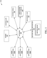
- FIG. 1 depicts a conceptual diagram of an example system in which a controller enables replication of changes to application table data by generating before images of respective system tables without full logging.
- FIG. 2 depicts a conceptual box diagram of example components of the controller of FIG. 1 .
- FIG. 3 depicts an example flowchart by which the controller of FIG. 1 may enable replication of changes to application table data by generating before images of respective system tables without full logging of the system table.
- aspects of the present disclosure relate to providing data replication, while more particular aspects of the present disclosure relate to detecting and then replicating changes to application data tables using a default level of logging for system tables that does not include continuous capturing of before and after images of system tables. While the present disclosure is not necessarily limited to such applications, various aspects of the disclosure may be appreciated through a discussion of various examples using this context.
- DBMS database management systems
- RDBMS relational DBMS
- the structure of the data within the tables i.e., the location of each data point in relation to the rest of the data
- meaning i.e., metadata
- an RDBMS there may be data as generated or modified by a user for an application as stored in application data tables, and the application data tables may be supported by system tables that may relate to one or more application data tables.
- changes to the application data tables as described herein may include some or all data manipulation language (DML) changes
- changes to the system table may include some or all data definition language (DDL) changes.
- DML data manipulation language
- DDL data definition language
- Modern computing environments may provide mechanisms for providing data replication, such that data of the database (e.g., data of the system tables and application data tables) is stored at more than one location (e.g., at more than one node, disk, site, etc.).
- data of the database e.g., data of the system tables and application data tables
- a conventional environment may utilize a roll-forward recovery log to provide data replication.
- RDBMS RDBMS
- a mechanism of the conventional environment may allow elements of the conventional environment (e.g., where an element of the conventional environment includes an application) to request “full logging” of the system tables rather than a “default” amount of logging that an RDBMS (e.g., where the default amount of logging requires less logging than full logging, and wherein the default logging includes the amount of logging that an RDBMS executes unless specified otherwise).
- a default amount of logging for tables may not include capturing and/or storing the before image of an update operation, capturing and/or storing an image for a delete operation, and may only include capturing and/or storing a partial after image for an update operation. With this default amount of logging, it may be difficult or impossible for a conventional system to provide reliable and robust data replication using a roll-forward recovery log.
- full logging as described herein and executed by conventional database environments to provide data replication includes capturing and storing system table row states before and/or after a respective change, these states referred to as a “before image” and an “after image” of the respective row.
- a conventional replication system is configured to determine which column values changed.
- a conventional replication system uses the command from the roll-forward recovery log to recreate the respective values at the second (or third, or fourth, etc.) replication site. In this way, changes to system table data may be replicated immediately upon detecting an update to the original.
- this process of full logging is functionally continuous, such that before images and after images must be automatically and consistently captured as part of the replication process after every single operation.
- storing each of these images with full logging may decrease operational performance and/or increase disk utilization of a respective conventional RDBMS.
- Such decreased performance and/or increased disk utilization may be especially impactful for time-critical system table changes.
- problems that result from this constant full-logging may be expensive and time-consuming to fix.
- a replication of an application data table is requested without full logging of a system table, accounting for any such DDL change without logging requires extensive and error-prone manual intervention and correction by human database administrators.
- aspects of this disclosure may solve or otherwise address some or all of these problems.
- aspects of the disclosure may eliminate the need for full logging of all changes to the system tables of the RDBMS (e.g., where changes to the system tables include any DDL changes), instead enabling a computing environment to replicate all changes to application data tables for one or more applications from default logging of system tables and application data tables of an RDBMS environment.
- One or more computing components (these computing components including or otherwise making using of a processing unit executing instructions stored on a memory) may provide this functionality, these one or more computing components hereinafter referred to collectively as a controller.
- This controller may be integrated into one or more components of a computing environment that utilizes an RDBMS and a roll-forward recovery log to provide this functionality.
- aspects of this disclosure may be able to replicate changes to default values and/or constraints of the RDBMS using substantially only the default logging of system tables as described herein. Though replicating changes to the application tables is predominantly discussed throughout for purposes of illustration, it is to be understood that the techniques described herein are also largely applicable to replicating these changes to the default values and/or constraints, such that these changes to default values and/or constraints may be replicated without full logging of the system tables.
- FIG. 1 depicts environment 100 in which controller 110 works with RDBMS 120 to replicate system data from one or more system tables 140 in order to subsequently replicate application data from one or more application data tables 150 .
- RDBMS 120 may be used to manage (e.g., create, retrieve, update, or delete) data as requested by user applications 130 A, 130 B, 130 C (collectively “user applications 130 ”). Commands to thusly generate/modify/delete/etc. data as sent from user applications 130 may be reflected in roll-forward recovery log 160 .
- system tables 140 There may be any number of system tables 140 , application data tables 150 , and/or roll-forward recovery logs 160 for any number of different user applications 130 (e.g., whether different instances of a single user application 130 and/or different user applications entirely) as are supported by environment 100 .
- Network 180 may include a computing network over which computing messages may be sent and/or received.
- network 180 may include the Internet, a local area network (LAN), a wide area network (WAN), a wireless network such as a wireless LAN (WLAN), or the like.
- Network 180 may comprise copper transmission cables, optical transmission fibers, wireless transmission, routers, firewalls, switches, gateway computers and/or edge servers.
- a network adapter card or network interface in each computing/processing device may receive messages and/or instructions from and/or through network 180 and forward the messages and/or instructions for storage or execution or the like to a respective memory or processor of the respective computing/processing device.
- network 180 is depicted as a single entity in FIG. 1 for purposes of illustration, in other examples network 180 may include a plurality of private and/or public networks over which controller 110 may detect changes to application data tables using only default logging as described herein.
- user applications 130 and RDBMS 120 may communicate together over a first part of network 180
- RDBMS 120 , controller 110 , system tables 140 , application tables 150 , and roll-forward recovery logs 160 communicate together over a second part of network 180
- controller 110 , roll-forward recovery logs 160 , and before image repository 170 communicate together over a third part of network, etc.
- controller 110 may be similar to computing system 200 of FIG. 2 that includes a processor communicatively coupled to a memory that includes instructions that, when executed by the processor, cause controller 110 to execute one or more operations described below.
- the computing device of RDBMS 120 may include a first version of system table 140 and/or application tables 150 for user applications 130 (e.g., while recovery log 160 is still stored on a separate standalone computing device).
- Controller 110 may determine a before image of the respective system table 140 entries that relate to the respective application data tables 150 for one or more respective user application 130 .
- controller 110 may detect a request from user application 130 A for data replication, in response to which controller 110 may determine the before image of rows and columns of system table 140 that correspond to the respective application data table 150 for user application 130 A.
- Controller 110 may determine this before image without direct access (e.g., where not having direct access includes controller 110 being physically remote from the database that stores application data table 150 and controller 110 does not have write access to application data table 150 ) to system table 140 , RDBMS 120 , and/or application data table 150 data files.
- controller 110 may query system table 140 for entries related to respective application data tables 150 on which table structure change detection is desired. Such a query may essentially request data of all of the field values for each entry of system table 140 for each application data table 150 being replicated.
- Controller 110 may query system table 140 using structured query language (SQL) or the like.
- SQL structured query language
- Controller 110 may use code generation as understood by one of ordinary skill in the art to encode the values from system table 140 returned from the query into one or more before images 172 that reflect each respective entry (e.g., data points of indicated rows and columns of system table 140 ), and may store the generated before image 172 in before image repository 170 .
- controller 110 may generate (using code generation) before image 172 such that what is generated is substantially similar to a before image that would have been captured as part of full logging of system table 140 for a conventional RDBMS replication system.
- Controller 110 may generate and store each before image 172 such that each before image 172 indicates a corresponding point within roll-forward recovery log 160 at which before image 172 was generated (e.g., and therein a point at which before image 172 was accurate at that point in roll-forward recovery log 160 ). In some examples, controller 110 may generate a respective before image 172 for each row of system table 140 that relates to the respective application data table 150 .
- Controller 110 may query system table 140 and use code generation to generate one or more before images 172 at a rate that is far less than the continuous rate of logging that is utilized by conventional RDBMS replication systems. For example, controller 110 may only query system table 140 once at an initial startup. If at any point controller 110 detects a potential lapse in the data replication process, controller 110 may fully reinitialize the replication system in much the same way as an initial startup (e.g., such that controller 110 may query the relevant tables using SQL). Controller 110 may store all values gathered and generated from this query at a location external to RDBMS 120 .
- controller 110 may identify any updates and/or deletes to system table 140 . For example, controller 110 may crawl through roll-forward recovery log 160 to identify updates and/or deletes to system table 140 . Once identified, controller 110 may update the stored before image 172 to reflect this update and/or delete to system table 140 .
- controller 110 may use this identifier to determine which code generated row image the delete applies to. Once controller 110 determines the respective row, controller 110 may gather before image 172 that corresponds to this row from before image repository 170 . Once the respective before image 172 is gathered, controller 110 may use code generation to apply the delete operation to before image 172 to generate a new before image 172 , saving this new before image 172 into before image repository 170 . Controller 110 may further identify the point within roll-forward recovery log 160 that this newly generated before image 172 applies to, and store the new before image 172 to correlate to this point.
- controller 110 may find the identifier from the partial image stored within the update in the roll-forward recovery log 160 .
- This partial image may be logged by RDBMS 120 as part of the default logging as described above.
- controller 110 may use it to identify the respective before image 172 that corresponds to this respective row of the, and overlay the logged partial after image on the respective previously generated before image 172 .
- Controller 110 may use code generation to turn this overlaid image into a new before image 172 for system table 140 , again saving the respective point in the roll-forward recovery log 160 that it corresponds to. In this way, controller 110 may maintain a complete and accurate history of system table 140 entries without requiring the full logging of system table 140 .
- controller 110 may include or be part of a computing system that includes a processor configured to execute instructions stored on a memory to execute the techniques described herein.
- FIG. 2 is a conceptual box diagram of such computing system 200 . While computing system 200 is depicted as a single entity (e.g., within a single housing) for the purposes of illustration, in other examples, controller 110 may comprise two or more discrete physical systems (e.g., within two or more discrete housings).
- Computing system 200 may include interface 210 , processor 220 , and memory 230 .
- Computing system 200 may include any number or amount of interface(s) 210 , processor(s) 220 , and/or memory(s) 230 .
- Computing system 200 may include components that enable controller 110 to communicate with (e.g., send data to and receive and utilize data transmitted by) devices that are external to controller 110 .
- computing system 200 may include interface 210 that is configured to enable controller 110 and components within computing system 200 (e.g., such as processor 220 ) to communicate with entities external to computing system 200 .
- interface 210 may be configured to enable controller 110 to communicate with RDBMS 120 , system table 140 , application data table 150 , roll-forward recovery log 160 , before image repository 170 , or the like.
- Interface 210 may include one or more network interface cards, such as Ethernet cards and/or any other types of interface devices that can send and receive information. Any suitable number of interfaces may be used to perform the described functions according to particular needs.
- controller 110 may be configured to cause computing device 110 to generate before images 172 of system table 140 without full logging. Controller 110 may utilize processor 220 to thusly generate these before images.
- Processor 220 may include, for example, microprocessors, digital signal processors (DSPs), application specific integrated circuits (ASICs), field-programmable gate arrays (FPGAs), and/or equivalent discrete or integrated logic circuits. Two or more of processor 220 may be configured to work together to manage functionality.
- Processor 220 may generate images of system table 140 according to instructions 232 stored on memory 230 of controller 110 .
- Memory 230 may include a computer-readable storage medium or computer-readable storage device.
- memory 230 may include one or more of a short-term memory or a long-term memory.
- Memory 230 may include, for example, random access memories (RAM), dynamic random-access memories (DRAM), static random-access memories (SRAM), magnetic hard discs, optical discs, floppy discs, flash memories, forms of electrically programmable memories (EPROM), electrically erasable and programmable memories (EEPROM), or the like.
- processor 220 may enable application data table 150 replication by generate before images of system table 140 without full logging as described herein according to instructions 232 of one or more applications (e.g., software applications) stored in memory 230 of computing system 200 .
- applications e.g., software applications
- gathered or predetermined data or techniques or the like as used by processor 220 to generate before images of system table 140 may be stored within memory 230 .
- memory 230 may include information described above as described from system table 140 , application data table 150 , roll-forward recovery log 160 , and/or before image repository 170 .
- controller 110 may be the primary location of before image repository 170 , and/or controller 110 may store local copies of data from system table 140 , application data table 150 , or roll-forward recovery log 160 .
- controller 110 may store replication data 234 with which application data table 150 may be replicated.
- Replication data 234 may include image data 236 , which may include before images 172 that were generated by controller 110 as described herein.
- Image data 236 may also include respective points in roll-forward recovery, which may be stored in roll-forward recovery data 242 .
- Replication data 234 may also include query data 238 , which may be the results that were returned by querying system table 140 to generate an initial before image 172 .
- Replication data 234 may also include change data 240 that indicates updates and/or deletes or the like to system table 140 with which controller 110 generated new before images.
- controller 110 may discard query data 238 and change data 240 upon generating the respective before image 172 , though in other examples controller 110 may keep query data 238 , change data 240 , and/or all before images 172 so that a record of application data table 150 information over time may be tracked.
- controller 110 may enable replicating application data table 150 information via generating before images of system tables 140 without full logging.
- controller 110 may provide this functionality according to flowchart 300 depicted in FIG. 3 .
- Flowchart 300 of FIG. 3 is discussed with relation to FIG. 1 for purposes of illustration, though it is to be understood that other systems may be used to execute flowchart 300 of FIG. 3 in other examples.
- controller 110 may execute a different method than flowchart 300 of FIG. 3 , or controller 110 may execute a similar method with more or less steps in a different order, or the like.
- Controller 110 may detect a request to replicate data of application data tables 150 ( 302 ). Controller 110 may receive this request from one or more user applications 130 . In response to this request, controller 110 may send a query to system table 140 ( 304 ). This query may be an SQL query. Controller 110 may send this query to only those portions of system table 140 that relate to the respective application data tables 150 . Controller 110 may structure the query to return values of system table 140 that relate to application data tables 150 . Further, as will be understood by one of ordinary skill in the art, in some examples controller 110 may additionally or alternatively structure the query to gather default values and/or constraints of RDBMS 120 .
- Controller 110 may use the result from the query to generate before image 172 of system table 140 ( 306 ). Controller 110 may use code generation to generate before image 172 . Controller 110 may store before image 172 in a location that is external to RDBMS 120 , such as in before image repository 170 . Controller 110 may generate one or more before images 172 to include application data table 150 values. Alternatively, or additionally, controller 110 may generate one or more before images 172 to include default values and/or constraints of RDBMS 120 .
- Controller 110 may monitor for changes to system table 140 ( 308 ). For example, controller 110 may crawl through or scrape roll-forward recovery log 160 for data that indicates changes to system table 140 . Controller 110 may monitor for whether or not delete operations that relate to system table 140 entity values are detected ( 310 ).
- controller 110 may generate a new before image 172 for system table 140 that reflects this delete operation. For example, controller 110 may find an identifier of the delete operation. Using this delete operation, controller 110 may identify a row of system table 140 that the delete operation corresponds to. Once this row is identified, controller 110 may use code generation to generate a new before image that reflects this delete operation. Controller 110 may further correlate this new before image with a point in roll-forward recovery log 160 at which point this before image is current and accurate.
- controller 110 may determine whether or not the changes to system table 140 are an update operation ( 314 ). If no update operation is detected, controller 110 continues monitoring ( 308 ). If controller 110 does detect an update operation, controller 110 may gather the partial after image from the default logging on the update operation. Using this partial after image controller 110 identifies an identifier of the update, from which controller 110 further identifies a row of system table 140 to which the update relates to. Once controller 110 identifies this row using the partial after image, controller 110 uses code generation to generate a new before image 172 ( 316 ). Controller 110 may generate this before image by overlaying the partial after image over the before image that controller 110 previously generated for the identified row. As with the delete operation, controller 110 may further correlate this new before image with a point in roll-forward recovery log 160 at which point this before image is current and accurate.
- controller 110 may continue with this pseudo-continuous cycle of monitoring for system table 140 changes in order to replicate application data table 150 changes (and/or default values and constraints) in a loop 308 - 316 .
- This loop may enable controller 110 to provide this data replication without full logging of system tables 140 .
- the present invention may be a system, a method, and/or a computer program product at any possible technical detail level of integration
- the computer program product may include a computer readable storage medium (or media) having computer readable program instructions thereon for causing a processor to carry out aspects of the present invention
- the computer readable storage medium can be a tangible device that can retain and store instructions for use by an instruction execution device.
- the computer readable storage medium may be, for example, but is not limited to, an electronic storage device, a magnetic storage device, an optical storage device, an electromagnetic storage device, a semiconductor storage device, or any suitable combination of the foregoing.
- a non-exhaustive list of more specific examples of the computer readable storage medium includes the following: a portable computer diskette, a hard disk, a random access memory (RAM), a read-only memory (ROM), an erasable programmable read-only memory (EPROM or Flash memory), a static random access memory (SRAM), a portable compact disc read-only memory (CD-ROM), a digital versatile disk (DVD), a memory stick, a floppy disk, a mechanically encoded device such as punch-cards or raised structures in a groove having instructions recorded thereon, and any suitable combination of the foregoing.
- RAM random access memory
- ROM read-only memory
- EPROM or Flash memory erasable programmable read-only memory
- SRAM static random access memory
- CD-ROM compact disc read-only memory
- DVD digital versatile disk
- memory stick a floppy disk
- a mechanically encoded device such as punch-cards or raised structures in a groove having instructions recorded thereon
- a computer readable storage medium is not to be construed as being transitory signals per se, such as radio waves or other freely propagating electromagnetic waves, electromagnetic waves propagating through a waveguide or other transmission media (e.g., light pulses passing through a fiber-optic cable), or electrical signals transmitted through a wire.
- Computer readable program instructions described herein can be downloaded to respective computing/processing devices from a computer readable storage medium or to an external computer or external storage device via a network, for example, the Internet, a local area network, a wide area network and/or a wireless network.
- the network may comprise copper transmission cables, optical transmission fibers, wireless transmission, routers, firewalls, switches, gateway computers and/or edge servers.
- a network adapter card or network interface in each computing/processing device receives computer readable program instructions from the network and forwards the computer readable program instructions for storage in a computer readable storage medium within the respective computing/processing device.
- Computer readable program instructions for carrying out operations of the present invention may be assembler instructions, instruction-set-architecture (ISA) instructions, machine instructions, machine dependent instructions, microcode, firmware instructions, state-situation data, configuration data for integrated circuitry, or either source code or object code written in any combination of one or more programming languages, including an object oriented programming language such as Smalltalk, C++, or the like, and procedural programming languages, such as the “C” programming language or similar programming languages.
- the computer readable program instructions may execute entirely on the user's computer, partly on the user's computer, as a stand-alone software package, partly on the user's computer and partly on a remote computer or entirely on the remote computer or server.
- the remote computer may be connected to the user's computer through any type of network, including a local area network (LAN) or a wide area network (WAN), or the connection may be made to an external computer (for example, through the Internet using an Internet Service Provider).
- electronic circuitry including, for example, programmable logic circuitry, field-programmable gate arrays (FPGA), or programmable logic arrays (PLA) may execute the computer readable program instructions by utilizing state information of the computer readable program instructions to personalize the electronic circuitry, in order to perform aspects of the present invention.
- These computer readable program instructions may be provided to a processor of a general purpose computer, special purpose computer, or other programmable data processing apparatus to produce a machine, such that the instructions, which execute via the processor of the computer or other programmable data processing apparatus, create means for implementing the functions/acts specified in the flowchart and/or block diagram block or blocks.
- These computer readable program instructions may also be stored in a computer readable storage medium that can direct a computer, a programmable data processing apparatus, and/or other devices to function in a particular manner, such that the computer readable storage medium having instructions stored therein comprises an article of manufacture including instructions which implement aspects of the function/act specified in the flowchart and/or block diagram block or blocks.
- the computer readable program instructions may also be loaded onto a computer, other programmable data processing apparatus, or other device to cause a series of operational steps to be performed on the computer, other programmable apparatus or other device to produce a computer implemented process, such that the instructions which execute on the computer, other programmable apparatus, or other device implement the functions/acts specified in the flowchart and/or block diagram block or blocks.
- each block in the flowchart or block diagrams may represent a module, segment, or portion of instructions, which comprises one or more executable instructions for implementing the specified logical function(s).
- the functions noted in the blocks may occur out of the order noted in the Figures.
- two blocks shown in succession may, in fact, be accomplished as one step, executed concurrently, substantially concurrently, in a partially or wholly temporally overlapping manner, or the blocks may sometimes be executed in the reverse order, depending upon the functionality involved.
Abstract
Description
Claims (20)
Priority Applications (1)
| Application Number | Priority Date | Filing Date | Title |
|---|---|---|---|
| US17/001,664 US11860894B2 (en) | 2020-08-24 | 2020-08-24 | Database management system data replication |
Applications Claiming Priority (1)
| Application Number | Priority Date | Filing Date | Title |
|---|---|---|---|
| US17/001,664 US11860894B2 (en) | 2020-08-24 | 2020-08-24 | Database management system data replication |
Publications (2)
| Publication Number | Publication Date |
|---|---|
| US20220058207A1 US20220058207A1 (en) | 2022-02-24 |
| US11860894B2 true US11860894B2 (en) | 2024-01-02 |
Family
ID=80269699
Family Applications (1)
| Application Number | Title | Priority Date | Filing Date |
|---|---|---|---|
| US17/001,664 Active 2041-05-30 US11860894B2 (en) | 2020-08-24 | 2020-08-24 | Database management system data replication |
Country Status (1)
| Country | Link |
|---|---|
| US (1) | US11860894B2 (en) |
Citations (16)
| Publication number | Priority date | Publication date | Assignee | Title |
|---|---|---|---|---|
| US20050131966A1 (en) * | 2003-12-15 | 2005-06-16 | Sbc Knowledge Ventures, L.P. | Architecture of database application with robust online recoverability |
| US20050193024A1 (en) * | 2004-02-27 | 2005-09-01 | Beyer Kevin S. | Asynchronous peer-to-peer data replication |
| US7051051B1 (en) * | 2000-12-05 | 2006-05-23 | Ncr Corp. | Recovering from failed operations in a database system |
| US20070174315A1 (en) * | 2006-01-18 | 2007-07-26 | Avraham Leff | Compressing state in database replication |
| US20080249988A1 (en) * | 2007-04-06 | 2008-10-09 | International Business Machines Corporation | Computer programming method and system for performing a reversal of selected structured query language operations within a database transaction |
| US20100036803A1 (en) * | 2008-08-08 | 2010-02-11 | Oracle International Corporation | Adaptive filter index for determining queries affected by a dml operation |
| US20120030172A1 (en) * | 2010-07-27 | 2012-02-02 | Oracle International Corporation | Mysql database heterogeneous log based replication |
| US20130006940A1 (en) * | 2011-06-30 | 2013-01-03 | Bmc Software, Inc. | Methods and apparatus related to completion of large objects within a db2 database environment |
| US20140258234A1 (en) * | 2013-03-11 | 2014-09-11 | AppGlu, Inc. | Synchronization of cms data to mobile device storage |
| US8903779B1 (en) | 2013-03-06 | 2014-12-02 | Gravic, Inc. | Methods for returning a corrupted database to a known, correct state |
| US9417890B2 (en) | 2013-04-12 | 2016-08-16 | Microsoft Technology Licensing, Llc | Compilation of transformation in recalculation user interface |
| WO2017023426A1 (en) | 2015-07-31 | 2017-02-09 | Google Inc. | Phone number canonicalization and information discoverability |
| US20170286475A1 (en) * | 2016-04-05 | 2017-10-05 | International Business Machines Corporation | Change stream analytics for data replication systems |
| US20180136911A1 (en) | 2015-06-18 | 2018-05-17 | United Parcel Service Of America, Inc. | Automation of canonical model usage in application development processes |
| US10216820B1 (en) * | 2016-12-14 | 2019-02-26 | Gravic, Inc. | Method and apparatus for resolving constraint violations in a database replication system |
| US20190265971A1 (en) | 2015-01-23 | 2019-08-29 | C3 Iot, Inc. | Systems and Methods for IoT Data Processing and Enterprise Applications |
-
2020
- 2020-08-24 US US17/001,664 patent/US11860894B2/en active Active
Patent Citations (18)
| Publication number | Priority date | Publication date | Assignee | Title |
|---|---|---|---|---|
| US7051051B1 (en) * | 2000-12-05 | 2006-05-23 | Ncr Corp. | Recovering from failed operations in a database system |
| US20080046480A1 (en) | 2003-12-15 | 2008-02-21 | At&T Knowledge Ventures, L.P. | Architecture of database application with robust online recoverability |
| US20050131966A1 (en) * | 2003-12-15 | 2005-06-16 | Sbc Knowledge Ventures, L.P. | Architecture of database application with robust online recoverability |
| US20050193024A1 (en) * | 2004-02-27 | 2005-09-01 | Beyer Kevin S. | Asynchronous peer-to-peer data replication |
| US20070174315A1 (en) * | 2006-01-18 | 2007-07-26 | Avraham Leff | Compressing state in database replication |
| US20080249988A1 (en) * | 2007-04-06 | 2008-10-09 | International Business Machines Corporation | Computer programming method and system for performing a reversal of selected structured query language operations within a database transaction |
| US20100036803A1 (en) * | 2008-08-08 | 2010-02-11 | Oracle International Corporation | Adaptive filter index for determining queries affected by a dml operation |
| EP3410320A1 (en) | 2010-07-27 | 2018-12-05 | Oracle International Corporation | Mysql database - heterogeneous log based replication |
| US20120030172A1 (en) * | 2010-07-27 | 2012-02-02 | Oracle International Corporation | Mysql database heterogeneous log based replication |
| US20130006940A1 (en) * | 2011-06-30 | 2013-01-03 | Bmc Software, Inc. | Methods and apparatus related to completion of large objects within a db2 database environment |
| US8903779B1 (en) | 2013-03-06 | 2014-12-02 | Gravic, Inc. | Methods for returning a corrupted database to a known, correct state |
| US20140258234A1 (en) * | 2013-03-11 | 2014-09-11 | AppGlu, Inc. | Synchronization of cms data to mobile device storage |
| US9417890B2 (en) | 2013-04-12 | 2016-08-16 | Microsoft Technology Licensing, Llc | Compilation of transformation in recalculation user interface |
| US20190265971A1 (en) | 2015-01-23 | 2019-08-29 | C3 Iot, Inc. | Systems and Methods for IoT Data Processing and Enterprise Applications |
| US20180136911A1 (en) | 2015-06-18 | 2018-05-17 | United Parcel Service Of America, Inc. | Automation of canonical model usage in application development processes |
| WO2017023426A1 (en) | 2015-07-31 | 2017-02-09 | Google Inc. | Phone number canonicalization and information discoverability |
| US20170286475A1 (en) * | 2016-04-05 | 2017-10-05 | International Business Machines Corporation | Change stream analytics for data replication systems |
| US10216820B1 (en) * | 2016-12-14 | 2019-02-26 | Gravic, Inc. | Method and apparatus for resolving constraint violations in a database replication system |
Non-Patent Citations (6)
| Title |
|---|
| "The Transaction Log (SQL Server)," Microsoft Docs, Oct. 23, 2019, 10 pages. <https://docs.microsoft.com/en-us/sql/relational-databases/logs/the-transaction-log-sql-server?view=sql-server-ver15>. |
| Anonymous, "Method for verifying integrity of database replications," IP.com, Disclosure No. IPCOM000247521D, Sep. 14, 2016, 3 pages. <https://ip.com/IPCOM/000247521>. |
| Anonymous, "Method to Avoid Replication Delays for Large Update Queries," IP.com, Disclosure No. IPCOM000245749D, Apr. 4, 2016, 2 pages. <https://ip.com/IPCOM/000245749>. |
| Anonymous, "Push-Down of Data Change Detection in Relational Database Systems," IP.com, Disclosure No. IPCOM000176076D, Nov. 4, 2008, 4 pages. <https://priorart.ip.com/IPCOM/000176076>. |
| Goldsmith et al., "Technique for Data Recovery Excluding Portions of the Log without Requiring a Full Image Copy," IP.com, Disclosure No. IPCOM000106503D, Nov. 1, 1993, 3 pages. <https://priorart.ip.com/IPCOM/000106503>. |
| Majety, "Minimal Logging," SQL Server Central, Aug. 26, 2013, 8 pages. <https://www.sqlservercentral.com/articles/minimal-logging>. |
Also Published As
| Publication number | Publication date |
|---|---|
| US20220058207A1 (en) | 2022-02-24 |
Similar Documents
| Publication | Publication Date | Title |
|---|---|---|
| US11537482B2 (en) | Method and apparatus for reading and writing committed data | |
| US10788998B2 (en) | Logging changes to data stored in distributed data storage system | |
| US11520670B2 (en) | Method and apparatus for restoring data from snapshots | |
| US10802921B2 (en) | Systems and methods including committing a note to master and slave copies of a data volume based on sequential operation numbers | |
| KR101780340B1 (en) | Method, system, and computer-readable storage medium for creating validated database snapshots for provisioning virtual databases | |
| US8832028B2 (en) | Database cloning | |
| US9141685B2 (en) | Front end and backend replicated storage | |
| US11074224B2 (en) | Partitioned data replication | |
| US11397749B2 (en) | Asynchronous replication of in-scope table data | |
| US20210326359A1 (en) | Compare processing using replication log-injected compare records in a replication environment | |
| US11386078B2 (en) | Distributed trust data storage system | |
| US20200034472A1 (en) | Asynchronous cache coherency for mvcc based database systems | |
| US11119866B2 (en) | Method and system for intelligently migrating to a centralized protection framework | |
| US10318330B2 (en) | Data-persisting temporary virtual machine environments | |
| US20210342378A1 (en) | External storage of unstructured database objects | |
| US10977137B2 (en) | Intelligent log gap detection to ensure necessary backup promotion | |
| US11860894B2 (en) | Database management system data replication | |
| US11436089B2 (en) | Identifying database backup copy chaining | |
| US11204890B2 (en) | System and method for archiving data in a decentralized data protection system | |
| US11243982B2 (en) | Immutable partitioning for databases | |
| US10776339B2 (en) | Intelligent log gap detection to prevent unnecessary backup promotion | |
| CN111522688A (en) | Data backup method and device for distributed system | |
| US11422970B2 (en) | Handling of data archiving events in a replication system | |
| CN110888895B (en) | Association-based access control delegation |
Legal Events
| Date | Code | Title | Description |
|---|---|---|---|
| AS | Assignment |
Owner name: INTERNATIONAL BUSINESS MACHINES CORPORATION, NEW YORK Free format text: ASSIGNMENT OF ASSIGNORS INTEREST;ASSIGNORS:JORY, MICHAEL;SEELEMANN, DIRK ALEXANDER, II;REEL/FRAME:053581/0025 Effective date: 20200821 |
|
| FEPP | Fee payment procedure |
Free format text: ENTITY STATUS SET TO UNDISCOUNTED (ORIGINAL EVENT CODE: BIG.); ENTITY STATUS OF PATENT OWNER: LARGE ENTITY |
|
| STPP | Information on status: patent application and granting procedure in general |
Free format text: NON FINAL ACTION MAILED |
|
| STPP | Information on status: patent application and granting procedure in general |
Free format text: FINAL REJECTION MAILED |
|
| STPP | Information on status: patent application and granting procedure in general |
Free format text: NON FINAL ACTION MAILED |
|
| STPP | Information on status: patent application and granting procedure in general |
Free format text: RESPONSE TO NON-FINAL OFFICE ACTION ENTERED AND FORWARDED TO EXAMINER |
|
| STPP | Information on status: patent application and granting procedure in general |
Free format text: NOTICE OF ALLOWANCE MAILED -- APPLICATION RECEIVED IN OFFICE OF PUBLICATIONS |
|
| STPP | Information on status: patent application and granting procedure in general |
Free format text: PUBLICATIONS -- ISSUE FEE PAYMENT VERIFIED |
|
| STCF | Information on status: patent grant |
Free format text: PATENTED CASE |