US11859513B2 - Moving blade for a wheel of a turbine engine - Google Patents
Moving blade for a wheel of a turbine engine Download PDFInfo
- Publication number
- US11859513B2 US11859513B2 US17/276,430 US201917276430A US11859513B2 US 11859513 B2 US11859513 B2 US 11859513B2 US 201917276430 A US201917276430 A US 201917276430A US 11859513 B2 US11859513 B2 US 11859513B2
- Authority
- US
- United States
- Prior art keywords
- upstream
- lip
- axis
- ribs
- rib
- Prior art date
- Legal status (The legal status is an assumption and is not a legal conclusion. Google has not performed a legal analysis and makes no representation as to the accuracy of the status listed.)
- Active, expires
Links
- 238000011144 upstream manufacturing Methods 0.000 claims abstract description 59
- 230000001154 acute effect Effects 0.000 claims description 20
- 239000007789 gas Substances 0.000 description 14
- 239000000463 material Substances 0.000 description 7
- 238000000034 method Methods 0.000 description 2
- 230000000295 complement effect Effects 0.000 description 1
- 238000010276 construction Methods 0.000 description 1
- 230000010354 integration Effects 0.000 description 1
- 238000005495 investment casting Methods 0.000 description 1
- 238000002955 isolation Methods 0.000 description 1
- 238000003754 machining Methods 0.000 description 1
- 230000003014 reinforcing effect Effects 0.000 description 1
- 230000000930 thermomechanical effect Effects 0.000 description 1
Images


Classifications
-
- F—MECHANICAL ENGINEERING; LIGHTING; HEATING; WEAPONS; BLASTING
- F01—MACHINES OR ENGINES IN GENERAL; ENGINE PLANTS IN GENERAL; STEAM ENGINES
- F01D—NON-POSITIVE DISPLACEMENT MACHINES OR ENGINES, e.g. STEAM TURBINES
- F01D5/00—Blades; Blade-carrying members; Heating, heat-insulating, cooling or antivibration means on the blades or the members
- F01D5/12—Blades
- F01D5/22—Blade-to-blade connections, e.g. for damping vibrations
- F01D5/225—Blade-to-blade connections, e.g. for damping vibrations by shrouding
-
- F—MECHANICAL ENGINEERING; LIGHTING; HEATING; WEAPONS; BLASTING
- F01—MACHINES OR ENGINES IN GENERAL; ENGINE PLANTS IN GENERAL; STEAM ENGINES
- F01D—NON-POSITIVE DISPLACEMENT MACHINES OR ENGINES, e.g. STEAM TURBINES
- F01D11/00—Preventing or minimising internal leakage of working-fluid, e.g. between stages
- F01D11/08—Preventing or minimising internal leakage of working-fluid, e.g. between stages for sealing space between rotor blade tips and stator
- F01D11/12—Preventing or minimising internal leakage of working-fluid, e.g. between stages for sealing space between rotor blade tips and stator using a rubstrip, e.g. erodible. deformable or resiliently-biased part
- F01D11/122—Preventing or minimising internal leakage of working-fluid, e.g. between stages for sealing space between rotor blade tips and stator using a rubstrip, e.g. erodible. deformable or resiliently-biased part with erodable or abradable material
-
- F—MECHANICAL ENGINEERING; LIGHTING; HEATING; WEAPONS; BLASTING
- F01—MACHINES OR ENGINES IN GENERAL; ENGINE PLANTS IN GENERAL; STEAM ENGINES
- F01D—NON-POSITIVE DISPLACEMENT MACHINES OR ENGINES, e.g. STEAM TURBINES
- F01D5/00—Blades; Blade-carrying members; Heating, heat-insulating, cooling or antivibration means on the blades or the members
- F01D5/30—Fixing blades to rotors; Blade roots ; Blade spacers
-
- F—MECHANICAL ENGINEERING; LIGHTING; HEATING; WEAPONS; BLASTING
- F05—INDEXING SCHEMES RELATING TO ENGINES OR PUMPS IN VARIOUS SUBCLASSES OF CLASSES F01-F04
- F05D—INDEXING SCHEME FOR ASPECTS RELATING TO NON-POSITIVE-DISPLACEMENT MACHINES OR ENGINES, GAS-TURBINES OR JET-PROPULSION PLANTS
- F05D2240/00—Components
- F05D2240/10—Stators
- F05D2240/12—Fluid guiding means, e.g. vanes
- F05D2240/127—Vortex generators, turbulators, or the like, for mixing
-
- F—MECHANICAL ENGINEERING; LIGHTING; HEATING; WEAPONS; BLASTING
- F05—INDEXING SCHEMES RELATING TO ENGINES OR PUMPS IN VARIOUS SUBCLASSES OF CLASSES F01-F04
- F05D—INDEXING SCHEME FOR ASPECTS RELATING TO NON-POSITIVE-DISPLACEMENT MACHINES OR ENGINES, GAS-TURBINES OR JET-PROPULSION PLANTS
- F05D2240/00—Components
- F05D2240/80—Platforms for stationary or moving blades
-
- F—MECHANICAL ENGINEERING; LIGHTING; HEATING; WEAPONS; BLASTING
- F05—INDEXING SCHEMES RELATING TO ENGINES OR PUMPS IN VARIOUS SUBCLASSES OF CLASSES F01-F04
- F05D—INDEXING SCHEME FOR ASPECTS RELATING TO NON-POSITIVE-DISPLACEMENT MACHINES OR ENGINES, GAS-TURBINES OR JET-PROPULSION PLANTS
- F05D2250/00—Geometry
- F05D2250/10—Two-dimensional
- F05D2250/18—Two-dimensional patterned
- F05D2250/182—Two-dimensional patterned crenellated, notched
-
- F—MECHANICAL ENGINEERING; LIGHTING; HEATING; WEAPONS; BLASTING
- F05—INDEXING SCHEMES RELATING TO ENGINES OR PUMPS IN VARIOUS SUBCLASSES OF CLASSES F01-F04
- F05D—INDEXING SCHEME FOR ASPECTS RELATING TO NON-POSITIVE-DISPLACEMENT MACHINES OR ENGINES, GAS-TURBINES OR JET-PROPULSION PLANTS
- F05D2260/00—Function
- F05D2260/20—Heat transfer, e.g. cooling
- F05D2260/221—Improvement of heat transfer
- F05D2260/2212—Improvement of heat transfer by creating turbulence
-
- Y—GENERAL TAGGING OF NEW TECHNOLOGICAL DEVELOPMENTS; GENERAL TAGGING OF CROSS-SECTIONAL TECHNOLOGIES SPANNING OVER SEVERAL SECTIONS OF THE IPC; TECHNICAL SUBJECTS COVERED BY FORMER USPC CROSS-REFERENCE ART COLLECTIONS [XRACs] AND DIGESTS
- Y02—TECHNOLOGIES OR APPLICATIONS FOR MITIGATION OR ADAPTATION AGAINST CLIMATE CHANGE
- Y02T—CLIMATE CHANGE MITIGATION TECHNOLOGIES RELATED TO TRANSPORTATION
- Y02T50/00—Aeronautics or air transport
- Y02T50/60—Efficient propulsion technologies, e.g. for aircraft
Definitions
- the present invention relates to the general field of movable vanes for a wheel of an aircraft turbomachine.
- an axial turbine of a turbomachine comprises a succession of axial stages arranged one behind the other.
- Each stage comprises a moving wheel with vanes forming the rotor and a nozzle with vanes forming the stator. The wheel is rotated opposite the corresponding nozzle.
- the moving wheel typically consists of an annular disc centred on the rotational axis Y of the wheel, to which a plurality of vanes are attached.
- a movable vane comprises an aerodynamic blade extending along a stacking axis Z of the vane.
- the movable vane further comprises an outer heel and an inner root delimiting the blade along the stacking axis Z.
- the blade is bounded along the stacking axis Z by an outer platform of the heel and an inner platform of the root.
- the outer platform comprises at least one lip, e.g. two, protruding outward from the outer platform.
- the lips are intended to co-operate in a form-fitting manner with an annular block of abradable material (e.g. honeycomb structure) attached to an outer casing surrounding the moving wheel to form a dynamic labyrinth-type seal.
- abradable material e.g. honeycomb structure
- the purpose of the labyrinth-type seals is to limit the passage of gas between the moving wheel and the block of abradable material, i.e. to maximise the amount of gas acting on the blades of the moving wheel to maximise the efficiency of the turbine and the turbomachine in general.
- the objective of the present invention is therefore to provide a simple, effective and economical solution to the above-mentioned problem.
- the present invention provides a movable vane for a wheel of an aircraft turbomachine, said vane comprising an aerodynamic blade extending along a stacking axis Z and an outer heel delimiting said blade along said stacking axis Z, said heel comprising a platform and a first lip protruding from said platform, the first lip being inclined upstream at an acute angle to said stacking axis Z, said first lip extending circumferentially along an axis of elongation X, characterised in that the heel comprises a row of ribs spaced apart from each other, said row comprising at least two ribs, said row of ribs extending along said axis of elongation X, each rib extending along said stacking axis Z from said platform to said first lip, each rib being arranged upstream of the first lip according to the direction of gas flow around said blade so as to generate turbulence upstream of said first lip.
- the ribs make it possible to create aerodynamic turbulence which form a curtain opposing the passage of gases from upstream to downstream, so as to limit the passage of gases between the moving wheel (respectively the movable vane) and the block of abradable material, and thus maximise efficiency.
- the vane according to the invention may comprise one or more of the following characteristics, taken in isolation from each other or in combination with each other:
- the present invention further relates to a moving wheel for an aircraft turbomachine, comprising a disc carrying on its periphery an annular row of vanes as described above.
- the present invention also relates to an aircraft turbomachine, comprising at least one vane as previously described or a wheel as previously described.
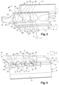
- FIG. 1 is a schematic detail side view of a movable vane for a moving wheel of an aircraft turbomachine
- FIG. 2 is a perspective detail view of the vane shown in FIG. 1 ;
- FIG. 3 is a perspective front view of the vane shown in FIGS. 1 and 2 ;
- FIG. 4 is a top view of the vane illustrated in FIGS. 1 to 3 , in a plane P perpendicular to a stacking axis Z of the vane, illustrating via a sketch the dimensional parameters of the ribs.
- FIGS. 1 to 4 show a movable vane 1 for a moving wheel of an aircraft turbomachine, and more precisely for a moving wheel of a low-pressure turbine of the turbomachine.
- the movable vane 1 could be intended to equip a high-pressure turbine of the turbomachine.
- the vane 1 comprises an aerodynamic blade 2 extending along a stacking axis Z.
- the blade 2 comprises a leading edge 3 and a trailing edge 4 opposite the leading edge 3 .
- the blade 2 comprises an intrados side face 5 and an extrados side face 6 opposite to the intrados side face 5 , with the intrados and extrados side faces 5 , 6 connecting the leading edge 3 to the trailing edge 4 .
- the blade 2 is profiled along a mean line connecting the leading edge 3 to the trailing edge 4 , the mean line separating the vane 1 into an intrados side and an extrados side.
- the intrados and extrados faces 5 , 6 are curved, and respectively concave and convex.
- the terms “intrados” and “extrados” associated with the different elements of the vane 1 refer to the intrados and extrados sides.
- the leading edge 3 is positioned upstream of the trailing edge 4 , according to the direction of gas flow around the blade 2 , and generally following the direction of gas flow in the turbine.
- upstream and downstream are defined in relation to the direction of gas flow around the blade 2 (and more generally in the turbine).
- the vane 1 also comprises an outer heel 7 and an inner root defining the blade 2 along the stacking axis Z. More precisely, the blade 2 is delimited by an inner platform of the root and an outer platform 8 of the heel 7 .
- a moving wheel comprises a disc with an annular row of vanes 1 on its periphery.
- each root comprises a bulb configured to be engaged in a complementary recess in the disc.
- the wheel (respectively the vane 1 ) is mobile around an axis of rotation Y coaxial with the axis of the turbomachine. As shown by the arrow in FIGS. 2 and 3 , the vane 1 is movable in rotation about the axis Y from the intrados to the extrados, and in other words here in a trigonometric (counterclockwise) direction of rotation.
- the terms “inner”, “outer”, “internal” or “external” are defined in relation to the axis of rotation Y of the vane 1 (and more generally of the moving wheel).
- the heel 7 of the vane 1 also comprises a first lip 9 protruding outwards from the outer platform 8 .
- the first lip 9 is inclined upstream at an acute angle to the stacking axis Z.
- the first lip 9 extends circumferentially along an axis of elongation X.
- the heel 7 comprises a row of ribs 10 a - 10 c spaced at a distance from each other.
- the row comprises at least two ribs 10 a - 10 c .
- the row of ribs 10 a - 10 c extends along the axis of elongation X.
- Each rib 10 a - 10 c (or leaf) extends along the stacking axis Z from the outer platform 8 to the first lip 9 .
- Each rib 10 a - 10 c is arranged upstream of the first lip 9 according to the direction of gas flow around the blade 2 so as to generate turbulence upstream of the first lip 9 .
- the heel 7 of the vane 1 comprises a first lip 9 and a second lip 11 spaced apart from each other, the second lip 11 being located downstream of the first lip 9 .
- the first lip 9 and the second lip 11 are hereinafter referred to as the upstream lip 9 and the downstream lip 11 respectively.
- the upstream lip 9 is inclined upstream at an angle of 30° to the stacking axis Z, the angle being measured in a plane which is both coincident with the rotational axis Y of the vane 1 and the stacking axis Z of the vane 1 .
- the upstream lip 9 could be inclined upstream at an acute angle of between 25° and 35° to the stacking axis Z.
- the downstream lip 11 extends along the stacking axis Z from the outer platform 8 .
- the downstream lip 11 could be inclined upstream at an angle of up to 10° to the stacking axis Z.
- Tilting the lips 9 and 11 upstream increases the aerodynamic turbulence and thus strengthens the curtain formed by this turbulence, which opposes the passage of gases from upstream to downstream, so as to limit the passage of gas between the moving wheel (respectively the movable vane 1 ) and a block of abradable material 12 .
- the outer platform 8 of the vane 1 comprises, from upstream to downstream, an upstream spoiler 13 extending upstream of the upstream lip 9 , an upstream surface 13 a , an downstream surface 13 b , a central plate 14 extending between the upstream lip 9 and the downstream lip 11 , and a downstream spoiler 15 extending downstream of the downstream lip 11 .
- the heel 7 also comprises two reinforcing tabs 16 between the upstream lip 9 and the plate 14 , these tabs 16 being located at each end of the upstream lip 9 .
- the plate 14 comprises a rib 17 centered on the mean line, with the rib 17 joining the upstream lip 9 to the downstream lip 11 .
- the plate 14 also comprises two recesses 18 on either side of the rib 17 .
- the upstream and downstream lips 9 , 11 are designed to co-operate in a form-fitting manner with an annular block of abradable material 12 (e.g. a honeycomb structure) attached to an outer casing surrounding the moving wheel to form a labyrinth-type seal.
- abradable material 12 e.g. a honeycomb structure
- the outer platforms of the movable vanes 1 of a same wheel are shaped to interlock with each other so as to externally delimit a portion of flowpath in which a gas stream flows.
- the outer platforms are thus arranged side by side.
- Each external platform 8 is delimited laterally by a male flank 19 able to fit into a female flank 20 of an adjacent vane and a female flank 20 able to receive a male flank 19 of an adjacent vane.
- the male and female flanks 19 , 20 are respectively arranged on the extrados and intrados sides.
- the row comprises between two and five ribs.
- the row comprises three ribs 10 a - 10 c , referred as first rib 10 a , second rib 10 b and third rib 10 c from the extrados to the intrados respectively.
- These three ribs 10 a - 10 c are spaced apart from each other.
- the ribs 10 a - 10 c are positioned at a constant pitch from the male flank 19 (extrados side).
- the first rib 10 a is positioned close to the male flank 19 .
- the third rib 10 c is positioned away from the female flank 20 .
- the heel 7 comprises a protrusion 21 between the third rib 10 c and the female flank 20 .
- the upstream lip 9 extends circumferentially along an axis of elongation X.
- at least one of the ribs 10 a - 10 c is inclined at an acute angle A to the axis of elongation X.
- the acute angle A is defined from the axis of elongation X to the corresponding rib 10 a - 10 c in a trigonometric (or counterclockwise) direction.
- the acute angle A is measured in a plane P perpendicular to the stacking axis Z.
- the acute angle A is greater than or equal to 30° and less than 90°.
- FIG. 4 is a top view on which the ribs 10 a - 10 c are sketched in dotted lines.
- the construction line T shown in FIG. 4 corresponds to the origin of the upstream lip 9 .
- At least one of the ribs 10 a - 10 c has a parallelogram-shaped cross-sectional profile in a sectional plane perpendicular to the stacking axis Z and passing through the corresponding rib 10 a - 10 c.
- each of the three ribs 10 a - 10 c has a parallelogram-shaped profile.
- each of the ribs 10 a - 10 c comprises two flat and parallel intrados side walls 22 , the intrados side walls 22 being at a distance B from each other.
- the distance B is between 0.5 and 3 mm.
- the distance B corresponds to the thickness of the rib.
- the distance B is measured in a plane P perpendicular to the stacking axis Z.
- front wall 23 , opposite intrados side walls 22 are extrados side walls 22 a.
- the distance B is the same for all three ribs 10 a - 10 c and is equal to 1 mm.
- each of the ribs 10 a - 10 c comprises a flat front wall 23 .
- the upstream lip 9 comprises an outer surface 24 bounded by a straight downstream edge 25 and a straight side edge 26 arranged on the extrados side (hereafter referred to as the extrados side edge 26 ).
- the distance D between the downstream edge 25 and the front wall 23 is less than the length E of the extrados side edge 26 .
- the distance D and the length E are measured in a plane P perpendicular to the stacking axis Z.
- the distance D is identical for the three ribs 10 a - 10 c .
- the distance D is equal to 1.5 mm and the length E is equal to 2.5 mm.
- Each rib 10 a - 10 c comprises, on the extrados side, a connecting fillet 27 with the upstream lip 9 and a connecting fillet 27 with the upstream spoiler 13 .
- Each rib 10 a - 10 c comprises a rounding 28 between the front wall 23 and the side wall 22 orientated on the intrados side.
- the distance C along the axis of elongation X between two consecutive ribs 10 a - 10 c is between 2 and 5 mm.
- the distance C is measured in a plane P perpendicular to the stacking axis Z.
- the distance C is constant and equal to 3 mm.
- the ribs 10 a - 10 c have the same dimensional and geometrical characteristics.
- the dimensional and geometrical characteristics of each of the ribs may be different.
- the dimensional and geometrical characteristics of the ribs depend, among other things, on the predefined limit to the thermomechanical stress, the predefined limit to the mass of the vane and the integration of the vane.
- At least one rib can be installed upstream of the downstream lip 11 .
- a rib extends along the stacking axis Z from the plate 14 to the downstream lip 11 .
- Such a rib is configured to generate turbulence upstream of the downstream lip 11 .
- the technical characteristics associated with the ribs 10 a - 10 c of the upstream lip 9 are transposable to the ribs of the downstream lip 11 .
- the vane 1 for example, is produced using a method comprising, firstly, obtaining a raw foundry vane using a lost-wax casting process and, secondly, various machining operations carried out on the raw vane in order to obtain a vane 1 with final dimensions as detailed on the definition drawing.
Landscapes
- Engineering & Computer Science (AREA)
- Mechanical Engineering (AREA)
- General Engineering & Computer Science (AREA)
- Turbine Rotor Nozzle Sealing (AREA)
- Structures Of Non-Positive Displacement Pumps (AREA)
Applications Claiming Priority (3)
| Application Number | Priority Date | Filing Date | Title |
|---|---|---|---|
| FR1858340A FR3085993B1 (fr) | 2018-09-17 | 2018-09-17 | Aube mobile pour une roue d'une turbomachine |
| FR1858340 | 2018-09-17 | ||
| PCT/FR2019/052133 WO2020058612A1 (fr) | 2018-09-17 | 2019-09-13 | Aube mobile pour une roue d'une turbomachine |
Publications (2)
| Publication Number | Publication Date |
|---|---|
| US20220034231A1 US20220034231A1 (en) | 2022-02-03 |
| US11859513B2 true US11859513B2 (en) | 2024-01-02 |
Family
ID=63963247
Family Applications (1)
| Application Number | Title | Priority Date | Filing Date |
|---|---|---|---|
| US17/276,430 Active 2039-11-23 US11859513B2 (en) | 2018-09-17 | 2019-09-13 | Moving blade for a wheel of a turbine engine |
Country Status (5)
| Country | Link |
|---|---|
| US (1) | US11859513B2 (zh) |
| EP (1) | EP3853443B1 (zh) |
| CN (1) | CN112805451B (zh) |
| FR (1) | FR3085993B1 (zh) |
| WO (1) | WO2020058612A1 (zh) |
Families Citing this family (2)
| Publication number | Priority date | Publication date | Assignee | Title |
|---|---|---|---|---|
| FR3125085A1 (fr) * | 2021-07-12 | 2023-01-13 | Safran Aircraft Engines | Aube de turbomachine |
| FR3139856B1 (fr) * | 2022-09-21 | 2024-09-06 | Safran Aircraft Engines | Roue de turbomachine |
Citations (8)
| Publication number | Priority date | Publication date | Assignee | Title |
|---|---|---|---|---|
| DE102010017489A1 (de) | 2009-07-02 | 2011-01-05 | General Electric Co. | Turbinenmaschinenzugehörige Systeme und Vorrichtungen und Dichtungen für Turbinenmaschinen |
| FR2955142A1 (fr) | 2010-01-13 | 2011-07-15 | Snecma | Amortisseur de vibrations a pion entre talons d'aubes adjacentes en materiau composite d'une roue mobile de turbomachine. |
| FR2970999A1 (fr) | 2011-02-02 | 2012-08-03 | Snecma | Aubes de turbomachine en cmc, roue mobile de turbomachine et turbomachine les comportant et procede pour leur fabrication |
| EP2746537A1 (de) | 2012-12-21 | 2014-06-25 | MTU Aero Engines GmbH | Turbinenschaufel mit Deckband und Schneidezahn |
| US20150023793A1 (en) * | 2012-01-17 | 2015-01-22 | Snecma | Turbomachine rotor blade |
| US20150226070A1 (en) * | 2014-02-13 | 2015-08-13 | Pratt & Whitney Canada Corp. | Shrouded blade for a gas turbine engine |
| US20180010467A1 (en) * | 2016-07-06 | 2018-01-11 | General Electric Company | Shroud configurations for turbine rotor blades |
| US11215116B2 (en) * | 2017-02-23 | 2022-01-04 | Mitsubishi Power, Ltd. | Turbine moving blade and gas turbine |
Family Cites Families (6)
| Publication number | Priority date | Publication date | Assignee | Title |
|---|---|---|---|---|
| FR2907519B1 (fr) * | 2006-10-20 | 2011-12-16 | Snecma | Nageoire de plateforme de soufflante |
| FR3002870B1 (fr) * | 2013-03-07 | 2015-03-06 | Snecma | Procede de fabrication d'une aube de rotor pour une turbomachine |
| EP2801702B1 (fr) * | 2013-05-10 | 2020-05-06 | Safran Aero Boosters SA | Virole interne de redresseur de turbomachine avec joint abradable |
| EP2868867A1 (de) * | 2013-10-29 | 2015-05-06 | Siemens Aktiengesellschaft | Turbinenschaufel |
| BE1022513B1 (fr) * | 2014-11-18 | 2016-05-19 | Techspace Aero S.A. | Virole interne de compresseur de turbomachine axiale |
| JP6462332B2 (ja) * | 2014-11-20 | 2019-01-30 | 三菱重工業株式会社 | タービン動翼及びガスタービン |
-
2018
- 2018-09-17 FR FR1858340A patent/FR3085993B1/fr active Active
-
2019
- 2019-09-13 WO PCT/FR2019/052133 patent/WO2020058612A1/fr unknown
- 2019-09-13 US US17/276,430 patent/US11859513B2/en active Active
- 2019-09-13 EP EP19790641.5A patent/EP3853443B1/fr active Active
- 2019-09-13 CN CN201980065696.7A patent/CN112805451B/zh active Active
Patent Citations (9)
| Publication number | Priority date | Publication date | Assignee | Title |
|---|---|---|---|---|
| DE102010017489A1 (de) | 2009-07-02 | 2011-01-05 | General Electric Co. | Turbinenmaschinenzugehörige Systeme und Vorrichtungen und Dichtungen für Turbinenmaschinen |
| FR2955142A1 (fr) | 2010-01-13 | 2011-07-15 | Snecma | Amortisseur de vibrations a pion entre talons d'aubes adjacentes en materiau composite d'une roue mobile de turbomachine. |
| FR2970999A1 (fr) | 2011-02-02 | 2012-08-03 | Snecma | Aubes de turbomachine en cmc, roue mobile de turbomachine et turbomachine les comportant et procede pour leur fabrication |
| US20150023793A1 (en) * | 2012-01-17 | 2015-01-22 | Snecma | Turbomachine rotor blade |
| EP2746537A1 (de) | 2012-12-21 | 2014-06-25 | MTU Aero Engines GmbH | Turbinenschaufel mit Deckband und Schneidezahn |
| US20140178201A1 (en) * | 2012-12-21 | 2014-06-26 | MTU Aero Engines AG | Turbine blade having a shroud and a cutting tooth |
| US20150226070A1 (en) * | 2014-02-13 | 2015-08-13 | Pratt & Whitney Canada Corp. | Shrouded blade for a gas turbine engine |
| US20180010467A1 (en) * | 2016-07-06 | 2018-01-11 | General Electric Company | Shroud configurations for turbine rotor blades |
| US11215116B2 (en) * | 2017-02-23 | 2022-01-04 | Mitsubishi Power, Ltd. | Turbine moving blade and gas turbine |
Non-Patent Citations (1)
| Title |
|---|
| International Search Report and Written Opinion received for PCT Patent Application No. PCT/FR2019/052133, dated Feb. 3, 2020, 21 pages (9 pages of English Translation and 12 pages of Original Document). |
Also Published As
| Publication number | Publication date |
|---|---|
| US20220034231A1 (en) | 2022-02-03 |
| EP3853443B1 (fr) | 2023-10-25 |
| WO2020058612A1 (fr) | 2020-03-26 |
| EP3853443A1 (fr) | 2021-07-28 |
| FR3085993B1 (fr) | 2020-12-25 |
| CN112805451B (zh) | 2023-04-21 |
| CN112805451A (zh) | 2021-05-14 |
| FR3085993A1 (fr) | 2020-03-20 |
Similar Documents
| Publication | Publication Date | Title |
|---|---|---|
| US8721291B2 (en) | Flow directing member for gas turbine engine | |
| US20150064020A1 (en) | Turbine blade or vane with separate endwall | |
| US11795823B2 (en) | Method for designing vane of fan, compressor and turbine of axial flow type, and vane obtained by the designing | |
| US9638040B2 (en) | Blade of a row of rotor blades or stator blades for use in a turbomachine | |
| US10934849B2 (en) | Endwall contouring for a turbomachine | |
| EP2852736B1 (en) | Airfoil mateface sealing | |
| US11236627B2 (en) | Turbomachine stator element | |
| US10450869B2 (en) | Gas turbine compressor | |
| US20050036889A1 (en) | Turbine bucket tip shroud edge profile | |
| US11859513B2 (en) | Moving blade for a wheel of a turbine engine | |
| EP3090143B1 (en) | Array of components in a gas turbine engine | |
| US8777564B2 (en) | Hybrid flow blade design | |
| US20220065124A1 (en) | Assembly for a turbomachine | |
| US11078918B2 (en) | Inter-blade platform seal | |
| EP3740656B1 (en) | Article of manufacture | |
| EP2634375B1 (en) | Method of producing a seal between stationary and rotating components of a turbine engine | |
| US11686207B2 (en) | Gas turbine compressor | |
| US12116904B2 (en) | Movable vane for a wheel of a turbine engine | |
| US10648339B2 (en) | Contouring a blade/vane cascade stage | |
| US20220316346A1 (en) | Movable vane for a wheel of a turbine engine | |
| US11898468B2 (en) | Sub-assembly for a low-pressure compressor of an aircraft turbine engine | |
| US11814981B2 (en) | Turbine blade and steam turbine | |
| US20230383662A1 (en) | Annulus contouring |
Legal Events
| Date | Code | Title | Description |
|---|---|---|---|
| FEPP | Fee payment procedure |
Free format text: ENTITY STATUS SET TO UNDISCOUNTED (ORIGINAL EVENT CODE: BIG.); ENTITY STATUS OF PATENT OWNER: LARGE ENTITY |
|
| STPP | Information on status: patent application and granting procedure in general |
Free format text: APPLICATION UNDERGOING PREEXAM PROCESSING |
|
| AS | Assignment |
Owner name: SAFRAN AIRCRAFT ENGINES, FRANCE Free format text: ASSIGNMENT OF ASSIGNORS INTEREST;ASSIGNORS:DUPEYRE, RAPHAEL JEAN PHILIPPE;BASSERY, JOSSERAND JACQUES ANDRE;FANELLI, JEREMY JACQUES ATTILIO;AND OTHERS;REEL/FRAME:057802/0293 Effective date: 20190914 |
|
| STPP | Information on status: patent application and granting procedure in general |
Free format text: DOCKETED NEW CASE - READY FOR EXAMINATION |
|
| STPP | Information on status: patent application and granting procedure in general |
Free format text: NON FINAL ACTION MAILED |
|
| STPP | Information on status: patent application and granting procedure in general |
Free format text: RESPONSE TO NON-FINAL OFFICE ACTION ENTERED AND FORWARDED TO EXAMINER |
|
| STPP | Information on status: patent application and granting procedure in general |
Free format text: FINAL REJECTION MAILED |
|
| STPP | Information on status: patent application and granting procedure in general |
Free format text: NON FINAL ACTION MAILED |
|
| STPP | Information on status: patent application and granting procedure in general |
Free format text: EX PARTE QUAYLE ACTION MAILED |
|
| STPP | Information on status: patent application and granting procedure in general |
Free format text: RESPONSE TO EX PARTE QUAYLE ACTION ENTERED AND FORWARDED TO EXAMINER |
|
| STPP | Information on status: patent application and granting procedure in general |
Free format text: NOTICE OF ALLOWANCE MAILED -- APPLICATION RECEIVED IN OFFICE OF PUBLICATIONS |
|
| STPP | Information on status: patent application and granting procedure in general |
Free format text: PUBLICATIONS -- ISSUE FEE PAYMENT RECEIVED |
|
| STPP | Information on status: patent application and granting procedure in general |
Free format text: PUBLICATIONS -- ISSUE FEE PAYMENT VERIFIED |
|
| STCF | Information on status: patent grant |
Free format text: PATENTED CASE |