US11858566B2 - Track link having sensor-receiving cavities - Google Patents
Track link having sensor-receiving cavities Download PDFInfo
- Publication number
- US11858566B2 US11858566B2 US17/443,520 US202117443520A US11858566B2 US 11858566 B2 US11858566 B2 US 11858566B2 US 202117443520 A US202117443520 A US 202117443520A US 11858566 B2 US11858566 B2 US 11858566B2
- Authority
- US
- United States
- Prior art keywords
- link
- track
- cavity
- protrusion
- link body
- Prior art date
- Legal status (The legal status is an assumption and is not a legal conclusion. Google has not performed a legal analysis and makes no representation as to the accuracy of the status listed.)
- Active, expires
Links
- 238000000034 method Methods 0.000 claims abstract description 21
- 239000000463 material Substances 0.000 claims description 39
- 238000005242 forging Methods 0.000 claims description 18
- 238000007373 indentation Methods 0.000 claims description 16
- 238000007789 sealing Methods 0.000 claims description 13
- 238000003754 machining Methods 0.000 claims description 7
- 239000002994 raw material Substances 0.000 claims description 5
- 238000010438 heat treatment Methods 0.000 claims description 2
- 230000000712 assembly Effects 0.000 description 5
- 238000000429 assembly Methods 0.000 description 5
- 239000004593 Epoxy Substances 0.000 description 4
- 238000004382 potting Methods 0.000 description 4
- 238000004891 communication Methods 0.000 description 3
- 238000005259 measurement Methods 0.000 description 2
- 229910000831 Steel Inorganic materials 0.000 description 1
- 238000001035 drying Methods 0.000 description 1
- 229920001971 elastomer Polymers 0.000 description 1
- 239000000806 elastomer Substances 0.000 description 1
- 230000003993 interaction Effects 0.000 description 1
- 238000012986 modification Methods 0.000 description 1
- 230000004048 modification Effects 0.000 description 1
- 239000011343 solid material Substances 0.000 description 1
- 239000010959 steel Substances 0.000 description 1
Images


Classifications
-
- B—PERFORMING OPERATIONS; TRANSPORTING
- B62—LAND VEHICLES FOR TRAVELLING OTHERWISE THAN ON RAILS
- B62D—MOTOR VEHICLES; TRAILERS
- B62D55/00—Endless track vehicles
- B62D55/08—Endless track units; Parts thereof
- B62D55/18—Tracks
- B62D55/20—Tracks of articulated type, e.g. chains
- B62D55/205—Connections between track links
- B62D55/21—Links connected by transverse pivot pins
-
- B—PERFORMING OPERATIONS; TRANSPORTING
- B60—VEHICLES IN GENERAL
- B60Y—INDEXING SCHEME RELATING TO ASPECTS CROSS-CUTTING VEHICLE TECHNOLOGY
- B60Y2200/00—Type of vehicle
- B60Y2200/20—Off-Road Vehicles
- B60Y2200/25—Track vehicles
Definitions
- the present disclosure relates generally to track assemblies for machines, and more particularly, to a track link having sensor-receiving cavities.
- Track type machines typically utilize track chains on each side of the machine to engage the ground surface to propel the machine. Individual track links that form the track chains are connected to ground engaging elements, known as track shoes, to move the machine. These track links wear over time and may need to be replaced or serviced.
- a wear sensor may be placed in one or more of the track links to provide an indication of the wear of the respective track link.
- a material may be used to set, hold, and seal the sensor in the track link.
- the track link may include surface features that make it difficult to properly seal the material while the material sets, and thus the material may leak from the track link before it sets. Further, without a proper seal, the material may form an undesirable shape as the material sets (e.g., due to the leakage), and may not adequately hold and seal the sensor in place.
- the track link of the '526 patent includes a wear sensing device that can be held in a cavity of the track link by a potting epoxy.
- the track link of the '526 patent may, in some instances, provide inadequate sealing of the cavity while the potting epoxy is cured.
- a track link in one aspect, includes: a link body; a cavity formed in the link body configured to receive a sensing device; and a protrusion substantially surrounding the cavity, the protrusion including a substantially flat surface.
- a method of producing a track link includes: forming a general shape of a link body of the track link; forming a final shape the link body, the formed link body including a protrusion extending from a surface of the link body; forming a flat surface on the protrusion; and forming a cavity into the flat surface of the protrusion.
- a track link in yet another aspect, includes: a link body; at least one aperture in the link body configured to receive a track pin assembly; an indentation in the link body that extends substantially parallel to a longitudinal axis of the link body; a cavity formed in the link body configured to receive a sensing device; and a protrusion substantially surrounding the cavity, the protrusion including a substantially flat surface.
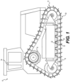
- FIG. 1 is a schematic view of an exemplary track type machine having one or more track links, according to aspects of the present disclosure.
- FIG. 2 is a perspective view of an exemplary track link isolated from the machine of FIG. 1 .
- FIGS. 3 A and 3 B are perspective views of the track link of FIG. 2 illustrating a sealing method, according to aspects of the present disclosure.
- FIG. 4 is a flowchart illustrating a method of producing a track link of FIGS. 1 and 2 .
- FIG. 1 illustrates a track type machine 10 according to the present disclosure.
- Machine 10 may embody any machine that is driven, propelled, positioned, and/or maneuvered by operating “continuous” track type traction device.
- Such machines may include, for example, track type tractors, skid steers, dozers, excavators, backhoes, track loaders, front shovels, rope shovels, or any other type of track-maneuverable machine.
- Machine 10 may include a pair of track assemblies 12 (only one shown) on opposing sides of machine 10 and driven by a driving mechanism 14 , such as a machine engine or other power source (not shown) via at least one drive gear or sprocket 16 .
- Each track assembly 12 may form separate endless loops.
- a plurality of track shoes 18 may be coupled to an outer surface of track assembly 12 in order to aid in the engagement of the ground surface.
- Track assembly 12 may include a plurality of other components that form the continuous track, ground-engaging portion of the drive system of machine 10 .
- Track assembly 12 may be coupled to an undercarriage assembly 20 that includes, for example, sprocket 16 , at least one idler, a plurality of rollers, and any other component of an undercarriage assembly known in the art.
- Track assembly 12 may be a chain that includes multiple structurally similar link subassemblies, each of which may include a pair of track links.
- a pair of track links may include a track link 22 and a respectively paired track link (not shown in FIG. 2 , which is a side view) that is parallel and spaced opposite from track link 22 .
- adjacent track links 22 may be coupled together via a plurality of pin assemblies 24 .
- Each track link 22 may be engaged by teeth of sprocket 16 to drive track assembly 12 around undercarriage assembly 20 .
- machine 10 may include at least one sensing device 32 (illustrated by dashed lines in FIGS. 1 and 3 A ) and at least one communication device 34 .
- Sensing device 32 may be an electronic device configured to detect a parameter of track assembly 12 and transmit a signal indicative of the parameter to communication device 34 and/or to a remote device.
- sensing device 32 may be a wear sensor and may be configured to measure a parameter associated with an amount of wear experienced by a track link 22 .
- a “wear parameter” is a measurement or other characteristic of a monitored component or sensing device 32 that may indicate an amount of wear experienced by the monitored component (e.g., when compared to a previous measurement or other previous characteristic).
- Sensing device 32 may be mounted in a track link 22 (as shown in FIG. 3 A ) and configured to detect a wear parameter thereof. Sensing device 32 may be configured to detect a wear parameter associated with wear of at least one surface of a body of track link 22 .
- sensing device 32 may include a wear portion 33 positioned at a surface of track link 22 such that, as the surface wears away, the wear portion 33 of sensing device 32 also wears away.
- sensing device 32 may use a depth sensor that uses ultrasonic waves, sound waves, lasers, etc. to determine a distance from sensing device 32 to a surface of track link 22 .
- One or more track links 22 may include sensing device 32 , as detailed further below.
- FIG. 2 is a perspective view of an exemplary track link 22 , according to aspects of the present disclosure.
- track link 22 may include a link body 50 having an outer surface 52 that defines a perimeter of the link body 50 , and thus defines a shape of track link 22 .
- Track link 22 may include a height between 200-280 mm, a width between 80-200 mm, and a thickness between 50-150 mm. However, it is understood that track link 22 may include any size and/or shape, as desired.
- Track link 22 may include an outward-facing surface 64 and an inward-facing surface (not shown). Outward-facing surface 64 may face away from machine 10 and the inward-facing surface may face toward machine 10 when track assembly 12 is installed on machine 10 .
- Each track link 22 may include one or more apertures 54 , 56 configured to receive at least a portion of track pin assemblies 24 in a manner known in the art.
- track link 22 includes a first aperture 54 and a second aperture 56 at respective opposite ends and/or spaced apart along a longitudinal axis of each track link 22 . It is understood that track link 22 may include any number of apertures 54 , 56 for receiving respective track pin assemblies 24 .
- Each track link 22 may also include one or more shoe holes 58 (unseen in FIG. 2 due to angle of perspective view) in a mounting surface 60 of link body 50 .
- Shoe holes 58 may extend as through-holes into the link body 50 substantially along a vertical axis of track link 22 .
- Track shoes 18 may be attached to track link 22 on mounting surface 60 .
- fasteners e.g., threaded fasteners
- bolts not shown
- corresponding threaded fasteners such as nuts or the like, may be disposed on the ends of the bolts.
- Track link 22 also includes a cavity 62 formed in link body 50 (e.g., in a surface 64 of link body 50 ) and may be configured to receive sensing device 32 , as detailed further below.
- Cavity 62 may include a size and shape to receive and accommodate at least a portion of sensing device 32 .
- cavity 62 may include a generally rectangular or square shape and may include a height of about 31 mm, a width of about 36 mm, and a depth of about 32 mm. However, it is understood that cavity 62 may include any size and/or shape, as desired.
- Cavity 62 may receive a containment material to secure the sensing device 32 in cavity 62 , as detailed further below.
- a passage 66 may be connected to cavity 62 and may be configured to receive a wear portion of sensing device 32 .
- the passage 66 may extend from a surface 68 to cavity 62 such that the wear portion of sensing device 32 may wear away with surface 68 .
- surface 68 may be a wear surface and cavity 62 may be located adjacent surface 68 .
- a wear surface may be any surface of link body 50 in which material wears away during use of track assembly 12 .
- material of surface 68 may be worn away through contact with components of undercarriage assembly 20 (e.g., the rollers) and/or other external materials (e.g., the ground).
- sensing device 32 may detect an amount of material that has been worn away from surface 68 .
- surface 68 may be generally flat to facilitate interaction with the components, such as the rollers, of undercarriage assembly 20 .
- surface 68 may include an uneven, non-flat surface, such as one or more curved surfaces or the like.
- Track link 22 may include one or more surface features 70 on surface 64 of link body 50 .
- the surface features may include one or more fastener protrusions 72 , one or more indentations 74 , and/or a cavity protrusion 76 .
- a “protrusion” is a portion of track link 22 that is raised or proud with respect to surrounding surfaces (e.g., surface 64 ).
- the fastener protrusions 72 may extend from surface 64 and may be generally aligned with shoe holes 58 .
- the fastener protrusions may provide additional support or structural integrity of shoe holes 58 for the fasteners.
- the one or more indentations 74 may include at least one indentation 74 that is substantially parallel with the longitudinal axis of track link 22 .
- the indentation 74 may provide clearance of the track link 22 from components of undercarriage assembly 20 (e.g., clearance from flanges of the rollers when the track link 22 becomes worn).
- the indentation 74 may extend substantially along the longitudinal axis of track link 22 and at least a portion of cavity 62 may be formed through a portion of indentation 74 .
- the track link 22 of the present disclosure may provide cavity protrusion 76 having a flat surface 78 to provide an improved sealing surface while the containment material sets.
- Cavity protrusion 76 may extend from surface 64 and may substantially surround cavity 62 .
- cavity protrusion 76 may include additional material on track link 22 such that cavity 62 is formed through cavity protrusion 76 , as detailed further below.
- At least a portion of protrusion 76 may extend from at least a portion of indentation 74 such that protrusion 76 interrupts indentation 74 .
- At least a portion of protrusion 76 may also be located adjacent at least one fastener protrusion 72 .
- protrusion 76 may abut at least a portion of at least one fastener protrusion 72 . As shown in FIGS.
- protrusion 76 may extend from surface 64 at a greater height than the one or more fasteners protrusions 72 . However, it is understood that protrusion 76 may extend from surface 64 at any height as desired, such as a height equal to, or less than, a height of the one or more fastener protrusions 72 .
- Protrusion 76 may include a continuous and uniform height around an entirety of cavity 62 such that protrusion 76 forms a uniform and continuous edge of cavity 62 .
- protrusion 76 may include a thickness (e.g., a height from surface 64 ) of about 10 mm, a width of about 40 mm, and a length of about 40 mm.
- the height, or thickness, of protrusion 76 from surface 64 may be formed and defined by flat surface 78 .
- Flat surface 78 may provide a planar surface that interacts with a sealing device 80 such that a seal is formed while the containment material sets, as detailed below with respect to FIGS. 3 A and 3 B .
- flat surface 78 may form a plane that may be spaced from a plane formed by surface 64 .
- Flat surface 78 may be substantially normal to the edge surfaces (e.g., surface 68 ). However, it is understood that flat surface may be non-normal to the edge surfaces.
- Flat surface 78 may include a shape substantially similar to a shape of cavity 62 .
- the flat surface 78 may form a generally rectangular or square shape.
- flat surface 78 of cavity protrusion 76 may include any size and/or shape, as desired.
- Cavity 62 may extend into link body 50 from flat surface 78 of protrusion 76 .
- cavity 62 may include a blind hole such that cavity 62 extends into only a portion of link body 50 at a depth less than an entirety of the depth of link body 50 . It is understood that cavity 62 may extend into link body 50 at any depth as desired, including extending through an entirety of link body 50 (e.g., from flat surface 78 through another surface of link body 50 opposite flat surface 78 ) so as to form an aperture.
- track link 22 may be employed in any machine that includes a tracked undercarriage that includes links coupled together to form one or more tracks.
- Cavity protrusion 76 of track link 22 described herein may provide flat surface 78 for providing an improved sealing surface during containment of sensing device 32 .
- Cavity protrusion 76 may also provide additional material such that cavity 62 may include an adequate depth for receiving sensing device 32 and receiving the containment material.
- FIGS. 3 A and 3 B illustrates a sealing method for sealing cavity 62 while the containment material sets, or otherwise solidifies.
- FIG. 3 A illustrates placement of sensing device 32 in cavity 62 .
- Sensing device 32 may be placed in cavity 62 and secured by the containment material. For example, sensing device 32 may rest against a rear surface (e.g., opposite an open portion) of cavity 62 and/or may rest against another surface of cavity 62 . However, it is understood that sensing device 32 may be placed in cavity 62 so as to not contact any surface of cavity 62 and may be held in place by the containment material.
- the wear portion 33 of sensing device 32 may be inserted into passage 66 when sensing device 32 is placed in cavity 62 .
- the wear portion 33 may be located at surface 68 such that the wear portion 33 wears when surface 68 wears.
- containment material may be poured, injected, or otherwise placed in cavity 62 around sensing device 32 such that the containment material covers at least a portion of sensing device 32 .
- the containment material may include, for example, a potting epoxy that may be poured and/or injected into cavity 62 with sensing device 32 .
- sealing device 80 may be placed on flat surface 78 (as shown in FIG.
- the sealing device 80 may include a plunger device having a handle 82 extending between a first end and a second end, and a seal 84 located at the second end of the handle 82 .
- Seal 84 may include an elastomer or other like material known in the art.
- the seal 84 may include a shape generally corresponding to a shape of cavity 62 (e.g., generally rectangular and/or square). A size of seal 84 may be generally larger than cavity 62 . Thus, seal 84 may be placed on flat surface 78 such that seal 84 substantially covers cavity 62 . In some embodiments, a portion of seal 84 may be inserted into a portion of cavity 62 when seal 84 is placed on flat surface 78 . Seal 84 may also include an indentation 86 such that excess containment material may flow through indentation 86 when seal 84 is placed on flat surface 78 . Accordingly, a portion of the containment material may flow onto flat surface 78 and as the containment material sets, the containment material may recede back towards cavity 62 .
- Flat surface 78 may also provide ease of clean-up of the excess containment material that sets on the flat surface 78 .
- the sealing device 80 may include any sealing device known in the art that includes a seal 84 for being placed over cavity 62 to seal cavity 62 while the containment material sets.
- containment material may include any material having sufficient strength to hold sensing device 32 in place while also being capable of allowing signals to be transmitted there through (e.g., to allow sensing device 32 to communicate with communication device 34 .
- FIG. 4 is a flowchart illustrating a method 400 of producing a track link 22 having a flat surface 78 .
- a step 402 may include forming a general shape of link body 50 of the track link 22 .
- Forming the general shape link body 50 may include heating raw material (e.g., steel) and forming the general shape of the link body 50 having an approximate shape and size of the final link body 50 .
- a step 404 may include forming a final shape of the link body 50 .
- the final shape of link body 50 may be formed by forging.
- the formed link body 50 includes a protrusion 76 extending from a surface 64 of the link body 50 .
- the forging may include die forging that includes one or more dies and/or hammer-type machines.
- the forging may include open-die forging in which one die is used to shape the link body 50 , or may include closed-die forging in which two dies (e.g., a top die and a bottom die) are used to shape the link body 50 .
- the shape of the forging may be incorporated into the dies as a negative image such that the impact of the dies on the heated raw material forms the raw material into the forged shape of the link body 50 .
- the dies may include a shape that includes the shape of the protrusion 76 such that the protrusion 76 is formed by the forging of the link body 50 .
- the sensing device 32 may be placed in a single track link 22 (e.g., and/or in less than an entirety of the track links 22 ) of the track assembly 12 and the dies for forging the track links 22 having a sensing device 32 may be different than the dies for forging the track links 22 that do not have a sensing device 32 .
- the dies for forging track links 22 having a sensing device 32 may include the shape of the protrusion 76 , while the dies for forging track links 22 that do not have a sensing device 32 may not include the shape of the protrusion 76 .
- less material may be used in forging track links 22 that do not have a sensing device 32 .
- an entirety of the track links 22 of track assembly 12 may include protrusion 76 regardless of whether a respective track link 22 includes sensing device 32 .
- a step 406 may include forming a flat surface 78 on protrusion 76 .
- Forming the flat surface 78 may include forging the flat surface 78 as the link body 50 is forged (e.g., the dies may include a shape of the protrusion 76 and flat surface 78 ).
- Forming the flat surface 78 may also include machining the flat surface 78 on protrusion 76 after link body 50 has been forged. For example, material of protrusion 76 may be removed to form flat surface 78 .
- flat surface 78 may be formed by a combination of forging and machining.
- a step 408 may include forming a cavity 62 into the flat surface 78 of protrusion 76 .
- material of link body 50 at protrusion 76 may be removed to form cavity 62 by machining.
- Passage 66 may also be formed during the forming of cavity 62 .
- flat surface 78 may be formed after cavity 62 has been formed.
- cavity 62 may be formed and then flat surface 78 may be formed around cavity 62 on protrusion 76 .
Landscapes
- Engineering & Computer Science (AREA)
- Chemical & Material Sciences (AREA)
- Combustion & Propulsion (AREA)
- Transportation (AREA)
- Mechanical Engineering (AREA)
- A Measuring Device Byusing Mechanical Method (AREA)
- Devices For Conveying Motion By Means Of Endless Flexible Members (AREA)
- Measuring Fluid Pressure (AREA)
- Investigating Or Analyzing Materials By The Use Of Ultrasonic Waves (AREA)
Abstract
Description
Claims (20)
Priority Applications (8)
| Application Number | Priority Date | Filing Date | Title |
|---|---|---|---|
| US17/443,520 US11858566B2 (en) | 2021-07-27 | 2021-07-27 | Track link having sensor-receiving cavities |
| CN202280051124.5A CN118139777A (en) | 2021-07-27 | 2022-07-20 | Track link with sensor receiving cavity |
| PCT/US2022/037655 WO2023009356A1 (en) | 2021-07-27 | 2022-07-20 | Track link having sensor-receiving cavities |
| AU2022319625A AU2022319625A1 (en) | 2021-07-27 | 2022-07-20 | Track link having sensor-receiving cavities |
| CA3226070A CA3226070A1 (en) | 2021-07-27 | 2022-07-20 | Track link having sensor-receiving cavities |
| JP2024502442A JP2024526807A (en) | 2021-07-27 | 2022-07-20 | Track link having sensor receiving cavity |
| KR1020247005661A KR20240069713A (en) | 2021-07-27 | 2022-07-20 | Track link with sensor receiving cavity |
| DE112022002804.1T DE112022002804T5 (en) | 2021-07-27 | 2022-07-20 | CHAIN LINK WITH SENSOR RECEIVING CAVES |
Applications Claiming Priority (1)
| Application Number | Priority Date | Filing Date | Title |
|---|---|---|---|
| US17/443,520 US11858566B2 (en) | 2021-07-27 | 2021-07-27 | Track link having sensor-receiving cavities |
Publications (2)
| Publication Number | Publication Date |
|---|---|
| US20230032368A1 US20230032368A1 (en) | 2023-02-02 |
| US11858566B2 true US11858566B2 (en) | 2024-01-02 |
Family
ID=82838926
Family Applications (1)
| Application Number | Title | Priority Date | Filing Date |
|---|---|---|---|
| US17/443,520 Active 2042-04-12 US11858566B2 (en) | 2021-07-27 | 2021-07-27 | Track link having sensor-receiving cavities |
Country Status (8)
| Country | Link |
|---|---|
| US (1) | US11858566B2 (en) |
| JP (1) | JP2024526807A (en) |
| KR (1) | KR20240069713A (en) |
| CN (1) | CN118139777A (en) |
| AU (1) | AU2022319625A1 (en) |
| CA (1) | CA3226070A1 (en) |
| DE (1) | DE112022002804T5 (en) |
| WO (1) | WO2023009356A1 (en) |
Citations (13)
| Publication number | Priority date | Publication date | Assignee | Title |
|---|---|---|---|---|
| US2168053A (en) * | 1934-08-25 | 1939-08-01 | Caterpillar Tractor Co | Endless track mechanism |
| US5749635A (en) | 1995-03-08 | 1998-05-12 | Umbarger; Daryl | Reversible track link for an endless track |
| US20080179946A1 (en) | 2007-01-31 | 2008-07-31 | Caterpillar Inc. | Tapered master link design for tracked undercarriage |
| US20110163595A1 (en) | 2008-05-29 | 2011-07-07 | Rolic Invest S.A.R.L. | Snow groomer track and snow groomer featuring such a track |
| US20150066291A1 (en) * | 2014-11-12 | 2015-03-05 | Caterpillar Inc. | Wear monitoring system for undercarriage component |
| US20150337522A1 (en) | 2014-05-20 | 2015-11-26 | Caterpillar Inc. | System for Monitoring Machine Components of Track-Type Mobile Machines |
| US20160131544A1 (en) * | 2014-11-10 | 2016-05-12 | Caterpillar Inc. | Thrust bias detection system |
| US20160178483A1 (en) * | 2014-12-19 | 2016-06-23 | Caterpillar Inc. | Wear sensing device having a housing |
| US9475526B2 (en) | 2014-08-23 | 2016-10-25 | Caterpillar Inc. | Track link having a wear sensing device |
| US20180050385A1 (en) * | 2015-10-20 | 2018-02-22 | Komatsu Ltd. | Track link and method for manufacturing track link |
| US10401315B2 (en) | 2016-03-14 | 2019-09-03 | Caterpillar Inc. | Track pin communication system and method |
| US20200070906A1 (en) * | 2018-08-30 | 2020-03-05 | Camso Inc. | Systems and methods for monitoring vehicles |
| US20210088416A1 (en) * | 2019-09-19 | 2021-03-25 | Berco S.P.A. | Monitoring system for automatically estimating and monitoring the correct alignment of the tracks, particularly of the track chains, and relevant method |
-
2021
- 2021-07-27 US US17/443,520 patent/US11858566B2/en active Active
-
2022
- 2022-07-20 CA CA3226070A patent/CA3226070A1/en active Pending
- 2022-07-20 DE DE112022002804.1T patent/DE112022002804T5/en active Pending
- 2022-07-20 WO PCT/US2022/037655 patent/WO2023009356A1/en not_active Ceased
- 2022-07-20 KR KR1020247005661A patent/KR20240069713A/en active Pending
- 2022-07-20 CN CN202280051124.5A patent/CN118139777A/en active Pending
- 2022-07-20 AU AU2022319625A patent/AU2022319625A1/en active Pending
- 2022-07-20 JP JP2024502442A patent/JP2024526807A/en active Pending
Patent Citations (13)
| Publication number | Priority date | Publication date | Assignee | Title |
|---|---|---|---|---|
| US2168053A (en) * | 1934-08-25 | 1939-08-01 | Caterpillar Tractor Co | Endless track mechanism |
| US5749635A (en) | 1995-03-08 | 1998-05-12 | Umbarger; Daryl | Reversible track link for an endless track |
| US20080179946A1 (en) | 2007-01-31 | 2008-07-31 | Caterpillar Inc. | Tapered master link design for tracked undercarriage |
| US20110163595A1 (en) | 2008-05-29 | 2011-07-07 | Rolic Invest S.A.R.L. | Snow groomer track and snow groomer featuring such a track |
| US20150337522A1 (en) | 2014-05-20 | 2015-11-26 | Caterpillar Inc. | System for Monitoring Machine Components of Track-Type Mobile Machines |
| US9475526B2 (en) | 2014-08-23 | 2016-10-25 | Caterpillar Inc. | Track link having a wear sensing device |
| US20160131544A1 (en) * | 2014-11-10 | 2016-05-12 | Caterpillar Inc. | Thrust bias detection system |
| US20150066291A1 (en) * | 2014-11-12 | 2015-03-05 | Caterpillar Inc. | Wear monitoring system for undercarriage component |
| US20160178483A1 (en) * | 2014-12-19 | 2016-06-23 | Caterpillar Inc. | Wear sensing device having a housing |
| US20180050385A1 (en) * | 2015-10-20 | 2018-02-22 | Komatsu Ltd. | Track link and method for manufacturing track link |
| US10401315B2 (en) | 2016-03-14 | 2019-09-03 | Caterpillar Inc. | Track pin communication system and method |
| US20200070906A1 (en) * | 2018-08-30 | 2020-03-05 | Camso Inc. | Systems and methods for monitoring vehicles |
| US20210088416A1 (en) * | 2019-09-19 | 2021-03-25 | Berco S.P.A. | Monitoring system for automatically estimating and monitoring the correct alignment of the tracks, particularly of the track chains, and relevant method |
Also Published As
| Publication number | Publication date |
|---|---|
| WO2023009356A1 (en) | 2023-02-02 |
| JP2024526807A (en) | 2024-07-19 |
| AU2022319625A1 (en) | 2024-02-08 |
| KR20240069713A (en) | 2024-05-20 |
| CN118139777A (en) | 2024-06-04 |
| US20230032368A1 (en) | 2023-02-02 |
| DE112022002804T5 (en) | 2024-05-23 |
| CA3226070A1 (en) | 2023-02-02 |
Similar Documents
| Publication | Publication Date | Title |
|---|---|---|
| EP3152101B1 (en) | Track pad wear indicator | |
| EP3183164B1 (en) | Track link having a wear sensing device | |
| US9169623B2 (en) | Wear monitoring system for track type machine | |
| EP3237270B1 (en) | Reversible track link system | |
| EP0478701A4 (en) | Track laying work vehicle | |
| JP4828059B2 (en) | Elastic crawler | |
| WO2017039998A1 (en) | Undercarriage assembly and track links for assembly | |
| US11858566B2 (en) | Track link having sensor-receiving cavities | |
| US20030184157A1 (en) | Grouser assembly | |
| US20160137240A1 (en) | Track Pads and Track Assembly | |
| EP3814204B1 (en) | Track assembly for a machine | |
| US11104393B2 (en) | Attachable track shoe cover | |
| KR20140055406A (en) | Method for assembling caterpillar track | |
| CA2342452A1 (en) | Rubber pad and lock pin for iron crawler belt | |
| JP3011527B2 (en) | Link belt automatic assembly device | |
| US2761744A (en) | Self-laying vehicle track | |
| CA3035737C (en) | Slider for track assembly of machine | |
| JPS6226295Y2 (en) | ||
| JPH10218048A (en) | Crawler device | |
| JPS61257506A (en) | Vibration compactor |
Legal Events
| Date | Code | Title | Description |
|---|---|---|---|
| FEPP | Fee payment procedure |
Free format text: ENTITY STATUS SET TO UNDISCOUNTED (ORIGINAL EVENT CODE: BIG.); ENTITY STATUS OF PATENT OWNER: LARGE ENTITY |
|
| STPP | Information on status: patent application and granting procedure in general |
Free format text: DOCKETED NEW CASE - READY FOR EXAMINATION |
|
| AS | Assignment |
Owner name: CATERPILLAR INC., ILLINOIS Free format text: ASSIGNMENT OF ASSIGNORS INTEREST;ASSIGNORS:KALMES, DONALD J.;SHOEMAKER, WILLIAM P.;ZHANG, LI;SIGNING DATES FROM 20210720 TO 20211019;REEL/FRAME:058392/0160 Owner name: ASIATRAK (TIANJIN) LTD., CHINA Free format text: ASSIGNMENT OF ASSIGNORS INTEREST;ASSIGNOR:ZHOU, YAODONG;REEL/FRAME:058392/0483 Effective date: 20211208 |
|
| STPP | Information on status: patent application and granting procedure in general |
Free format text: NON FINAL ACTION MAILED |
|
| STPP | Information on status: patent application and granting procedure in general |
Free format text: RESPONSE TO NON-FINAL OFFICE ACTION ENTERED AND FORWARDED TO EXAMINER |
|
| STPP | Information on status: patent application and granting procedure in general |
Free format text: NOTICE OF ALLOWANCE MAILED -- APPLICATION RECEIVED IN OFFICE OF PUBLICATIONS |
|
| STPP | Information on status: patent application and granting procedure in general |
Free format text: PUBLICATIONS -- ISSUE FEE PAYMENT RECEIVED |
|
| STPP | Information on status: patent application and granting procedure in general |
Free format text: PUBLICATIONS -- ISSUE FEE PAYMENT VERIFIED |
|
| STCF | Information on status: patent grant |
Free format text: PATENTED CASE |