US11857779B2 - Implantable cardioverter-defibrillator (ICD) system including substernal pacing lead - Google Patents
Implantable cardioverter-defibrillator (ICD) system including substernal pacing lead Download PDFInfo
- Publication number
- US11857779B2 US11857779B2 US16/742,385 US202016742385A US11857779B2 US 11857779 B2 US11857779 B2 US 11857779B2 US 202016742385 A US202016742385 A US 202016742385A US 11857779 B2 US11857779 B2 US 11857779B2
- Authority
- US
- United States
- Prior art keywords
- icd
- lead
- pacing
- electrode
- electrodes
- Prior art date
- Legal status (The legal status is an assumption and is not a legal conclusion. Google has not performed a legal analysis and makes no representation as to the accuracy of the status listed.)
- Active, expires
Links
- 210000002216 heart Anatomy 0.000 claims abstract description 82
- 210000001562 sternum Anatomy 0.000 claims abstract description 51
- 230000000747 cardiac effect Effects 0.000 claims abstract description 32
- 210000001370 mediastinum Anatomy 0.000 claims abstract description 25
- 230000035939 shock Effects 0.000 claims abstract description 24
- 238000002560 therapeutic procedure Methods 0.000 claims description 108
- 230000000638 stimulation Effects 0.000 claims description 29
- 208000001871 Tachycardia Diseases 0.000 claims description 28
- 230000006794 tachycardia Effects 0.000 claims description 15
- 230000000694 effects Effects 0.000 claims description 12
- 210000002837 heart atrium Anatomy 0.000 claims description 9
- 210000003516 pericardium Anatomy 0.000 claims description 7
- 208000003663 ventricular fibrillation Diseases 0.000 claims description 7
- 230000036471 bradycardia Effects 0.000 claims description 5
- 208000006218 bradycardia Diseases 0.000 claims description 5
- 206010047302 ventricular tachycardia Diseases 0.000 claims description 5
- 238000009125 cardiac resynchronization therapy Methods 0.000 claims description 3
- 210000004903 cardiac system Anatomy 0.000 abstract description 21
- 238000013194 cardioversion Methods 0.000 abstract description 14
- 239000013598 vector Substances 0.000 description 50
- 238000002474 experimental method Methods 0.000 description 39
- 230000001154 acute effect Effects 0.000 description 31
- 238000004873 anchoring Methods 0.000 description 19
- 238000007920 subcutaneous administration Methods 0.000 description 19
- 230000007246 mechanism Effects 0.000 description 18
- 238000000034 method Methods 0.000 description 16
- 239000004020 conductor Substances 0.000 description 15
- 206010040560 shock Diseases 0.000 description 12
- 230000002861 ventricular Effects 0.000 description 12
- 208000033988 Device pacing issue Diseases 0.000 description 10
- 210000000038 chest Anatomy 0.000 description 10
- 210000002417 xiphoid bone Anatomy 0.000 description 10
- 238000010586 diagram Methods 0.000 description 8
- 230000002169 extracardiac Effects 0.000 description 8
- 230000015654 memory Effects 0.000 description 8
- 210000001519 tissue Anatomy 0.000 description 7
- 230000001746 atrial effect Effects 0.000 description 6
- 238000005259 measurement Methods 0.000 description 6
- 241001465754 Metazoa Species 0.000 description 5
- 230000008901 benefit Effects 0.000 description 5
- 230000006870 function Effects 0.000 description 5
- 206010034486 Pericarditis adhesive Diseases 0.000 description 4
- 206010049447 Tachyarrhythmia Diseases 0.000 description 4
- 230000002051 biphasic effect Effects 0.000 description 4
- 238000002594 fluoroscopy Methods 0.000 description 4
- 210000001664 manubrium Anatomy 0.000 description 4
- 239000000463 material Substances 0.000 description 4
- 206010049418 Sudden Cardiac Death Diseases 0.000 description 3
- 206010003119 arrhythmia Diseases 0.000 description 3
- 230000006793 arrhythmia Effects 0.000 description 3
- 238000004891 communication Methods 0.000 description 3
- 210000003205 muscle Anatomy 0.000 description 3
- 239000012811 non-conductive material Substances 0.000 description 3
- 239000004814 polyurethane Substances 0.000 description 3
- 229920002635 polyurethane Polymers 0.000 description 3
- 210000002027 skeletal muscle Anatomy 0.000 description 3
- 241000282887 Suidae Species 0.000 description 2
- 210000000988 bone and bone Anatomy 0.000 description 2
- 239000003990 capacitor Substances 0.000 description 2
- 210000002808 connective tissue Anatomy 0.000 description 2
- 238000010276 construction Methods 0.000 description 2
- 238000005265 energy consumption Methods 0.000 description 2
- 239000004811 fluoropolymer Substances 0.000 description 2
- 229920002313 fluoropolymer Polymers 0.000 description 2
- 239000007943 implant Substances 0.000 description 2
- 210000002751 lymph Anatomy 0.000 description 2
- 239000003550 marker Substances 0.000 description 2
- 239000000203 mixture Substances 0.000 description 2
- 229920000642 polymer Polymers 0.000 description 2
- 229920001296 polysiloxane Polymers 0.000 description 2
- 230000008569 process Effects 0.000 description 2
- 230000004213 regulation of atrial cardiomyocyte membrane depolarization Effects 0.000 description 2
- 230000034225 regulation of ventricular cardiomyocyte membrane depolarization Effects 0.000 description 2
- 230000004044 response Effects 0.000 description 2
- 210000000115 thoracic cavity Anatomy 0.000 description 2
- 210000005166 vasculature Anatomy 0.000 description 2
- 102000053723 Angiotensin-converting enzyme 2 Human genes 0.000 description 1
- 108090000975 Angiotensin-converting enzyme 2 Proteins 0.000 description 1
- 206010003658 Atrial Fibrillation Diseases 0.000 description 1
- 241000283690 Bos taurus Species 0.000 description 1
- 241000282465 Canis Species 0.000 description 1
- 241000283073 Equus caballus Species 0.000 description 1
- 241000282324 Felis Species 0.000 description 1
- 208000010496 Heart Arrest Diseases 0.000 description 1
- 241000288906 Primates Species 0.000 description 1
- RTAQQCXQSZGOHL-UHFFFAOYSA-N Titanium Chemical compound [Ti] RTAQQCXQSZGOHL-UHFFFAOYSA-N 0.000 description 1
- 241001433070 Xiphoides Species 0.000 description 1
- 230000005856 abnormality Effects 0.000 description 1
- 239000000853 adhesive Substances 0.000 description 1
- 230000001070 adhesive effect Effects 0.000 description 1
- 238000004458 analytical method Methods 0.000 description 1
- 210000003484 anatomy Anatomy 0.000 description 1
- 208000008784 apnea Diseases 0.000 description 1
- 238000003491 array Methods 0.000 description 1
- 230000009286 beneficial effect Effects 0.000 description 1
- 239000000227 bioadhesive Substances 0.000 description 1
- 230000005540 biological transmission Effects 0.000 description 1
- 230000017531 blood circulation Effects 0.000 description 1
- 206010061592 cardiac fibrillation Diseases 0.000 description 1
- 206010007625 cardiogenic shock Diseases 0.000 description 1
- 210000000845 cartilage Anatomy 0.000 description 1
- 238000006243 chemical reaction Methods 0.000 description 1
- 239000011248 coating agent Substances 0.000 description 1
- 238000000576 coating method Methods 0.000 description 1
- 230000008602 contraction Effects 0.000 description 1
- QTCANKDTWWSCMR-UHFFFAOYSA-N costic aldehyde Natural products C1CCC(=C)C2CC(C(=C)C=O)CCC21C QTCANKDTWWSCMR-UHFFFAOYSA-N 0.000 description 1
- 230000001419 dependent effect Effects 0.000 description 1
- 238000013461 design Methods 0.000 description 1
- 238000001514 detection method Methods 0.000 description 1
- 238000004070 electrodeposition Methods 0.000 description 1
- 210000002815 epigastric artery Anatomy 0.000 description 1
- 210000003195 fascia Anatomy 0.000 description 1
- 230000002600 fibrillogenic effect Effects 0.000 description 1
- 238000001914 filtration Methods 0.000 description 1
- 210000004907 gland Anatomy 0.000 description 1
- 210000005003 heart tissue Anatomy 0.000 description 1
- 238000003780 insertion Methods 0.000 description 1
- 230000037431 insertion Effects 0.000 description 1
- ISTFUJWTQAMRGA-UHFFFAOYSA-N iso-beta-costal Natural products C1C(C(=C)C=O)CCC2(C)CCCC(C)=C21 ISTFUJWTQAMRGA-UHFFFAOYSA-N 0.000 description 1
- 231100000518 lethal Toxicity 0.000 description 1
- 230000001665 lethal effect Effects 0.000 description 1
- 230000033001 locomotion Effects 0.000 description 1
- 230000003211 malignant effect Effects 0.000 description 1
- 210000001349 mammary artery Anatomy 0.000 description 1
- 238000012806 monitoring device Methods 0.000 description 1
- 208000010125 myocardial infarction Diseases 0.000 description 1
- 210000004165 myocardium Anatomy 0.000 description 1
- 210000005036 nerve Anatomy 0.000 description 1
- 230000003287 optical effect Effects 0.000 description 1
- BPUBBGLMJRNUCC-UHFFFAOYSA-N oxygen(2-);tantalum(5+) Chemical compound [O-2].[O-2].[O-2].[O-2].[O-2].[Ta+5].[Ta+5] BPUBBGLMJRNUCC-UHFFFAOYSA-N 0.000 description 1
- 238000012545 processing Methods 0.000 description 1
- 208000012802 recumbency Diseases 0.000 description 1
- 238000011160 research Methods 0.000 description 1
- 230000029058 respiratory gaseous exchange Effects 0.000 description 1
- 230000033764 rhythmic process Effects 0.000 description 1
- 210000005241 right ventricle Anatomy 0.000 description 1
- 238000002633 shock therapy Methods 0.000 description 1
- 238000011301 standard therapy Methods 0.000 description 1
- 230000003068 static effect Effects 0.000 description 1
- PBCFLUZVCVVTBY-UHFFFAOYSA-N tantalum pentoxide Inorganic materials O=[Ta](=O)O[Ta](=O)=O PBCFLUZVCVVTBY-UHFFFAOYSA-N 0.000 description 1
- 230000008467 tissue growth Effects 0.000 description 1
- 229910052719 titanium Inorganic materials 0.000 description 1
- 239000010936 titanium Substances 0.000 description 1
- 230000005641 tunneling Effects 0.000 description 1
- 230000002792 vascular Effects 0.000 description 1
- 210000003462 vein Anatomy 0.000 description 1
- 238000012795 verification Methods 0.000 description 1
Images


Classifications
-
- A—HUMAN NECESSITIES
- A61—MEDICAL OR VETERINARY SCIENCE; HYGIENE
- A61N—ELECTROTHERAPY; MAGNETOTHERAPY; RADIATION THERAPY; ULTRASOUND THERAPY
- A61N1/00—Electrotherapy; Circuits therefor
- A61N1/02—Details
- A61N1/04—Electrodes
- A61N1/05—Electrodes for implantation or insertion into the body, e.g. heart electrode
-
- A—HUMAN NECESSITIES
- A61—MEDICAL OR VETERINARY SCIENCE; HYGIENE
- A61N—ELECTROTHERAPY; MAGNETOTHERAPY; RADIATION THERAPY; ULTRASOUND THERAPY
- A61N1/00—Electrotherapy; Circuits therefor
- A61N1/18—Applying electric currents by contact electrodes
- A61N1/32—Applying electric currents by contact electrodes alternating or intermittent currents
- A61N1/38—Applying electric currents by contact electrodes alternating or intermittent currents for producing shock effects
- A61N1/39—Heart defibrillators
- A61N1/3956—Implantable devices for applying electric shocks to the heart, e.g. for cardioversion
- A61N1/3962—Implantable devices for applying electric shocks to the heart, e.g. for cardioversion in combination with another heart therapy
- A61N1/39622—Pacing therapy
Definitions
- the present application relates to methods and medical devices for providing an implantable cardiac defibrillation system including a substernal pacing lead.
- An ICD system includes an ICD, which is a battery powered electrical shock device, that may include an electrical housing electrode (sometimes referred to as a can electrode), that is coupled to one or more electrical lead wires placed within the heart. If an arrhythmia is sensed, the ICD may send a pulse via the electrical lead wires to shock the heart and restore its normal rhythm. Owing to the inherent surgical risks in attaching and replacing electrical leads directly within or on the heart, subcutaneous ICD systems have been devised to provide shocks to the heart without placing electrical lead wires within the heart or attaching electrical wires directly to the heart.
- Subcutaneous ICD systems have been devised to deliver shocks to the heart by the use of a defibrillation lead placed subcutaneously on the torso.
- the subcutaneous ICD systems may require an output of around 80 Joules (J) of energy to provide effective defibrillation therapy.
- J Joules
- subcutaneous ICDs may require larger batteries and more storage capacitors than transvenous ICDs.
- the subcutaneous ICDs are generally larger in size than transvenous ICDs. The large size of the subcutaneous ICD may compromise patient comfort, decrease system longevity and/or increase cost of the system.
- conventional subcutaneous ICD systems are incapable of delivering anti-tachycardia pacing (ATP) without extreme discomfort to the patient, which is a standard therapy in transvenous ICDs to terminate lethal tachyarrhythmias without providing a shock.
- ATP anti-tachycardia pacing
- a method comprises generating a defibrillation pulse with an implantable cardiac device implanted within a patient, delivering the defibrillation pulse via at least one electrode of a defibrillation lead coupled to the implantable cardiac device, generating one or more pacing pulses with the implantable cardiac device, and delivering the one or more pacing pulses via at least one electrode of a pacing lead coupled to the implantable cardiac device and implanted at least partially along a posterior side of a sternum of the patent.
- an implantable cardioverter-defibrillator (ICD) system comprising an ICD implanted subcutaneously in a patient, a first lead having a proximal portion coupled to the ICD and a distal portion having one or more electrodes configured to deliver electrical stimulation therapy to a heart of the patient, and a second lead that includes a proximal portion coupled to the ICD and a distal portion having one or more electrodes, the distal portion of the second lead being implanted at least partially along a posterior side of a sternum of the patient.
- the ICD is configured to sense electrical signals of the heart of the patient using the one or more electrodes of the second lead, detect a tachycardia using the sensed electrical signals, and provide electrical stimulation therapy to the patient using the one or more electrodes of the first lead.
- FIG. 1 B is a side view of the patient with the implantable cardiac system having a substernal pacing lead.
- FIG. 1 C is a transverse view of the patient with the implantable cardiac system having a substernal pacing lead.
- FIG. 2 is a functional block diagram of an example configuration of electronic components of an example implantable cardioverter-defibrillator (ICD).
- ICD implantable cardioverter-defibrillator
- FIG. 3 is a flow diagram illustrating example operation of an implantable cardiac system having a substernal pacing lead.
- FIG. 4 is a graph illustrating strength-duration curves showing the capture thresholds obtained at various pulse widths during a first acute study.
- FIG. 5 is a graph illustrating strength-duration curves showing the capture thresholds obtained at various pulse widths during a second acute study.
- FIG. 6 is a graph illustrating strength-duration curves of electrical data from a third acute experiment with the lead positioned under the sternum in a first location.
- FIG. 7 is a graph illustrating strength-duration curves of electrical data from the third acute experiment with the lead positioned under the sternum in a second location.
- FIG. 8 is a graph illustrating strength-duration curves of electrical data from a third acute experiment with the lead positioned under the sternum in a third location.
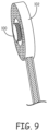
- FIG. 9 is a schematic diagram illustrating an example electrode of a pacing lead to be implanted in the substernal space.
- FIG. 10 A is a front view of a patient implanted with another example implantable cardiac system having a substernal defibrillation lead and pacing lead.
- FIG. 10 B is a transverse view of the patient with the implantable cardiac system of FIG. 10 A .
- FIGS. 1 A-C are conceptual diagrams of an implantable cardiac system 10 implanted within a patient 12 .
- FIG. 1 A is a front view of patient 12 implanted with implantable cardiac system 10 .
- FIG. 1 B is a side view of patient 12 with implantable cardiac system 10 .
- FIG. 1 C is a transverse view of patient 12 with implantable cardiac system 10 .
- Implantable cardiac system 10 includes an implantable medical device, in this example an ICD 14 , connected to a defibrillation lead 16 and a pacing lead 18 .
- ICD 14 is implanted subcutaneously on the left side of patient 12 above the ribcage.
- ICD 14 may, in some instances, be implanted between the left posterior axillary line and the left anterior axillary line of patient 12 .
- ICD 14 may, however, be implanted at other subcutaneous locations on patient 12 as described later.
- Defibrillation lead 16 includes a proximal end that includes a connector (not shown) configured to be connected to ICD 14 and a distal portion that includes electrodes 24 , 28 , and 30 .
- Defibrillation lead 16 extends subcutaneously above the ribcage from ICD 14 toward a center of the torso of patient 12 , e.g., toward xiphoid process 20 of patient 12 .
- defibrillation lead 16 bends or turns and extends superior subcutaneously above the ribcage and/or sternum, substantially parallel to sternum 22 .
- defibrillation lead 16 may be implanted at other locations, such as over sternum 22 , offset to the right of sternum 22 , angled lateral from sternum 22 at either the proximal or distal end, or the like.
- the therapy vector may, in one example, be viewed as a line that extends from a point on defibrillation electrode 24 , e.g., center of defibrillation electrode 24 , to a point on the housing electrode of ICD 14 , e.g., center of the housing electrode.
- the therapy vector between defibrillation electrode 24 and the housing electrode of ICD 14 is substantially across the right ventricle of heart 26 .
- defibrillation electrode 24 may be a flat ribbon electrode, paddle electrode, braided or woven electrode, mesh electrode, segmented electrode, directional electrode, patch electrode or other type of electrode besides an elongated coil electrode.
- defibrillation electrode 24 may be formed of a first segment and a second segment separated by a distance and having at least one sensing electrode located between the first and second defibrillation electrode segments.
- defibrillation lead 16 may include more than one defibrillation electrode.
- defibrillation lead 16 may include a second defibrillation electrode (e.g., second elongated coil electrode) near a proximal end of lead 16 or near a middle of lead 16 .
- Electrodes 28 and 30 may comprise ring electrodes, short coil electrodes, paddle electrodes, hemispherical electrodes, segmented electrodes, directional electrodes, or the like. Electrodes 28 and 30 of lead 16 may have substantially the same outer diameter as the lead body. In one example, electrodes 28 and 30 may have surface areas between 1.6-55 mm 2 . Electrodes 28 and 30 may, in some instances, have relatively the same surface area or different surface areas. Depending on the configuration of lead 16 , electrodes 28 and 30 may be spaced apart by the length of defibrillation electrode 24 plus some insulated length on each side of defibrillation electrode, e.g., approximately 2-16 cm.
- ICD 14 may obtain sensed electrical signals corresponding with electrical activity of heart 26 via a combination of sensing vectors that include combinations of electrodes 28 and/or 30 and the housing electrode of ICD 14 .
- ICD 14 may obtain electrical signals sensed using a sensing vector between electrodes 28 and 30 , obtain electrical signals sensed using a sensing vector between electrode 28 and the conductive housing electrode of ICD 14 , obtain electrical signals sensed using a sensing vector between electrode 30 and the conductive housing electrode of ICD 14 , or a combination thereof.
- ICD 14 may even obtain sensed electrical signals using a sensing vector that includes defibrillation electrode 24 .
- Pacing lead 18 is implanted within anterior mediastinum 36 such that electrodes 32 and 34 are located near the ventricle of heart 26 .
- the distal portion of pacing lead 18 may be implanted substantially within anterior mediastinum 36 such that electrodes 32 and 34 are located over a cardiac silhouette of the ventricle as observed via an anterior-posterior (AP) fluoroscopic view of heart 26 .
- pacing lead 18 may be implanted such that one or both of a unipolar pacing vector from electrode 32 to a housing electrode of ICD 14 and/or a unipolar pacing vector from electrode 34 to the housing electrode of ICD 14 are substantially across the ventricles of heart 26 .
- lead 16 may be implanted anywhere within the “substernal space” defined by the undersurface between the sternum and/or ribcage and the body cavity but not including the pericardium or other portion of heart 26 .
- the substernal space may alternatively be referred to by the terms “retrosternal space” or “mediastinum” or “infrasternal” as is known to those skilled in the art and includes the anterior mediastinum 36 .
- the sub sternal space may also include the anatomical region described in Baudoin, Y. P., et al., entitled “The superior epigastric artery does not pass through Larrey's space (trigonum sternocostale).” Surg. Radiol. Anat. 25.3-4 (2003): 259-62 as Larrey's space.
- the distal portion of lead 18 may be implanted in the region around the outer surface of heart 26 , but not attached to heart 26 .
- Pacing lead 18 includes an elongated lead body that contains one or more elongated electrical conductors (not illustrated) that extend within the lead body from the connector at the proximal lead end to electrodes 32 and 34 located along the distal portion of lead 18 .
- the elongated lead body may have a generally uniform shape along the length of the lead body.
- the elongated lead body may have a generally tubular or cylindrical shape along the length of the lead body.
- the elongated lead body may have a diameter of between 3 and 9 French (Fr) in some instances. However, lead bodies of less than 3 Fr and more than 9 Fr may also be utilized.
- the distal portion (or all of) the elongated lead body may have a flat, ribbon or paddle shape.
- the width across the flat portion of the flat, ribbon or paddle shape may be between 1 and 3.5 mm.
- the lead body of lead 18 may be formed from a non-conductive material, including silicone, polyurethane, fluoropolymers, mixtures thereof, and other appropriate materials, and shaped to form one or more lumens within which the one or more conductors extend.
- the techniques are not limited to such constructions.
- ICD 14 may generate and deliver pacing pulses to provide anti-tachycardia pacing (ATP), bradycardia pacing, post-shock pacing, or other pacing therapies or combination of pacing therapies via pacing vectors formed using electrodes 32 and/or 34 .
- the pacing therapy whether it be ATP, post-shock pacing, bradycardia pacing, or other pacing therapy may be painlessly provided in an ICD system without entering the vasculature or the pericardial space, and without being attached to the heart.
- pacing therapy provided by a subcutaneous ICD system if provided at all, is provided using pulse energies that may be uncomfortable for patient 12 .
- ICD 14 may deliver pacing pulses via pacing vector in which electrodes 32 and 34 together form the cathode (or anode) of the pacing vector and the housing electrode of ICD 14 functions as the anode (or cathode) of the pacing vector.
- ICD 14 may deliver pacing therapy via a pacing vector between electrode 32 (or electrode 34 ) and an electrode of defibrillation lead 16 , e.g., defibrillation electrode 24 or one of electrodes 28 or 30 .
- Pacing lead 18 may, in alternative embodiments, include more than two electrodes or only a single electrode. In instances in which pacing lead 18 includes more than two electrodes, ICD 14 may deliver pacing pulses and/or obtain sensed electrical signals of heart 26 via any of a number of combinations of the electrodes.
- lead 18 may be a quadripolar lead having four ring electrodes toward a distal end of lead 18 and ICD 14 may deliver pacing pulses and/or sense electrical signals via any of the combinations of electrodes or between any one of the electrodes and the housing electrode of ICD 14 .
- ICD 14 analyzes the sensed electrical signals obtained from one or more of the sensing vectors of pacing lead 18 and/or one or more of the sensing vectors of defibrillation lead 16 to detect tachycardia, such as ventricular tachycardia or ventricular fibrillation. ICD 14 may analyze the heart rate and/or morphology of the sensed electrical signals to monitor for tachyarrhythmia in accordance with any of a number of techniques known in the art. One example technique for detecting tachyarrhythmia is described in U.S. Pat. No.
- ICD 14 delivers one or more ATP therapies via the one or more pacing or therapy vectors of pacing lead 18 in response to detecting the tachycardia in an attempt to terminate the tachycardia without delivering a high voltage therapy, e.g., defibrillation shock or cardioversion shock. If the one or more ATP therapies are not successful or it is determined that ATP therapy is not desired, ICD 14 may deliver one or more cardioversion or defibrillation shocks via defibrillation electrode 24 of defibrillation lead 16 .
- ICD 14 may be configured to provide pacing therapy via a combination of therapy vectors that include combinations of electrodes 28 and/or 30 and the housing electrode of ICD 14 or via a therapy vector that includes one of electrodes 28 or 30 (or defibrillation electrode 24 ) and one of electrodes 32 or 34 of pacing lead 18 .
- ICD 14 may provide ATP and post-shock pacing using at least one electrode of defibrillation lead 16 .
- lead 18 may be only utilized for sensing.
- ICD 14 may provide ATP using a therapy vector using an electrode of pacing lead 18 and deliver post-shock therapy using a therapy vector including an electrode of lead 16 .
- the pacing lead may have one or more electrodes located over a cardiac silhouette of the atrium as observed via the AP fluoroscopic view of heart 26 and one or more electrodes located over a cardiac silhouette of the ventricle as observed via the AP fluoroscopic view of heart 26 .
- a pacing lead configured to deliver pacing pulses to only the atrium may, for example, have one or more electrodes located over a cardiac silhouette of the atrium as observed via the AP fluoroscopic view of heart 26 .
- two substernal pacing leads may be utilized with one being an atrial pacing lead implanted such that the electrodes are located over a cardiac silhouette of the atrium as observed via the AP fluoroscopic view of heart 26 and the other being a ventricle pacing lead being implanted such that the electrodes are located over a cardiac silhouette of the ventricle as observed via the AP fluoroscopic view of heart 26 .
- defibrillation lead 16 may include more than one defibrillation electrode and be placed further superior along sternum 22 such that a first therapy vector exists for the ventricle (e.g., via defibrillation electrode 24 ) and a second therapy vector exists for the atrium (e.g., via a second defibrillation electrode).
- defibrillation lead 16 may be placed further superior along sternum 22 such that a therapy vector between defibrillation electrode 24 and a housing electrode of ICD 14 is substantially across an atrium of heart 26 , such that extravascular ICD system 10 may be used to provide atrial therapies to treat atrial fibrillation.
- ICD 14 may include a housing that forms a hermetic seal that protects components of ICD 14 .
- the housing of ICD 14 may be formed of a conductive material, such as titanium.
- ICD 14 may also include a connector assembly (also referred to as a connector block or header) that includes electrical feedthroughs through which electrical connections are made between conductors within leads 16 and 18 and electronic components included within the housing.
- housing may house one or more processors, memories, transmitters, receivers, sensors, sensing circuitry, therapy circuitry, power sources and other appropriate components.
- the housing is configured to be implanted in a patient, such as patient 12 .
- lead 16 includes a lead body that contain one or more elongated electrical conductors (not illustrated) that extend through the lead body from the connector at a proximal lead end to the electrodes 24 , 28 , and 30 .
- the lead bodies of leads 16 and 18 may be formed from a non-conductive material, including silicone, polyurethane, fluoropolymers, mixtures thereof, and other appropriate materials, and shaped to form one or more lumens within which the one or more conductors extend.
- the respective conductors may electrically couple to circuitry, such as a therapy module or a sensing module, of ICD 14 via connections in connector assembly, including associated feedthroughs.
- the electrical conductors transmit therapy from a therapy module within ICD 14 to one or more of electrodes 24 , 28 , and 30 and transmit sensed electrical signals from one or more of electrodes 24 , 28 , and 30 to the sensing module within ICD 14 .
- the techniques are not limited to such constructions.
- the leads 16 and 18 may further include one or more anchoring mechanisms that are positioned along the length of the lead body.
- the anchoring mechanisms affix the lead 18 that is implanted in a substernal space in a fixed location to prevent dislodging of the lead 18 once it is implanted.
- the lead 18 may be anchored at one or more locations situated between the distal lead end positioned within the substernal space of patient 12 and a point along the length of the portion of the lead body at or near the insertion point of the lead body into the substernal space.
- the one or more anchoring mechanism(s) may either engage bone, fascia, muscle or other tissue of patient 12 or may simply be wedged therein to affix the lead under the sternum to prevent excessive motion or dislogment.
- various anchoring mechanisms described in this disclosure may additionally be utilized for delivery of a stimulation therapy as is known in the art.
- this disclosure describes anchoring mechanisms that are integrated into the lead body.
- a portion or segment of the lead body may be formed with materials that function to encase conductors and other elements internal to the lead while also anchoring the lead within the implant environment.
- anchoring mechanisms of the disclosure are described as discrete elements that may be formed in line with the lead body.
- the discrete components may be provided in a fixedly-secured relationship to the lead body.
- the anchoring mechanism may be detachedly coupled in a sliding relationship over the lead body.
- the anchoring mechanisms may include a passive anchoring mechanism, an active anchoring mechanism or a combination of both.
- the anchoring mechanism is coupled at a distal end of the lead body and may also function as an electrically active element.
- passive anchoring mechanisms include flanges, disks, pliant tines, flaps, porous structures such as a mesh-like element that facilitate tissue growth for engagement, bio-adhesive surfaces, and/or any other non-piercing elements.
- Examples of active anchoring mechanisms may include rigid tines, prongs, barbs, clips, screws, and/or other projecting elements that pierce and penetrate into tissue to anchor the lead.
- the lead may be provided with a side helix for engaging tissue.
- the various examples of the anchoring mechanisms may be deployable. As such, the anchoring mechanism assumes a first state during maneuvering of the lead (during which time the lead is disposed within a lumen of a delivery system or overtop a guidewire or stylet) to the desired implant location. Subsequently, the anchoring mechanism assumes a second state following the release of the lead from the delivery system into the substernal space to thereby anchor the distal end portion of the lead body relative to the adjacent tissue.
- the lead may be anchored through a suture that fixedly-secures the lead to the patient's musculature, tissue or bone at the xiphoid entry site.
- the suture may be sewn through pre-formed suture holes to the patient.
- ICD 14 , defibrillation lead 16 , and pacing lead 18 may be implanted at other locations.
- ICD 14 may be implanted in a subcutaneous pocket in the right pectoral region.
- defibrillation lead 16 may extend subcutaneously from the device toward the manubrium of the sternum and bend or turn and extend subcutaneously inferiorly from the manubrium of the sternum, substantially parallel with the sternum and pacing lead 18 may extend subcutaneously from the device toward the manubrium of the sternum to the desired location and bend or turn and extend inferior from the manubrium underneath/below sternum 22 to the desired location.
- implantable pulse generator 14 may be placed abdominally.
- system 10 is an ICD system that provides cardioversion/defibrillation and pacing therapy.
- these techniques may be applicable to other cardiac systems, including cardiac resynchronization therapy defibrillator (CRT-D) systems or other cardiac stimulation therapies, or combinations thereof.
- ICD 14 may be configured to provide electrical stimulation pulses to stimulate nerves, skeletal muscles, diaphragmatic muscles, e.g., for various neuro-cardiac applications and/or for apnea or respiration therapy.
- system 10 may not be limited to treatment of a human patient.
- system 10 may be implemented in non-human patients, e.g., primates, canines, equines, pigs, ovines, bovines, and felines. These other animals may undergo clinical or research therapies that may benefit from the subject matter of this disclosure.
- FIG. 2 is a functional block diagram of an example configuration of electronic components of an example ICD 14 .
- ICD 14 includes a control module 60 , sensing module 62 , therapy module 64 , communication module 68 , and memory 70 .
- the electronic components may receive power from a power source 66 , which may, for example, be a rechargeable or non-rechargeable battery.
- ICD 14 may include more or fewer electronic components.
- the described modules may be implemented together on a common hardware component or separately as discrete but interoperable hardware, firmware or software components. Depiction of different features as modules is intended to highlight different functional aspects and does not necessarily imply that such modules must be realized by separate hardware, firmware or software components. Rather, functionality associated with one or more modules may be performed by separate hardware, firmware or software components, or integrated within common or separate hardware, firmware or software components.
- Sensing module 62 is electrically coupled to some or all of electrodes 24 , 28 , 30 , 32 , and 34 via the conductors of leads 16 and 18 and one or more electrical feedthroughs, and is also electrically coupled to the housing electrode via conductors internal to the housing of ICD 14 . Sensing module 62 is configured to obtain signals sensed via one or more combinations of electrodes 24 , 28 , 30 , 32 , 34 , and the housing electrode of ICD 14 and process the obtained signals.
- sensing module 62 may be analog components, digital components or a combination thereof.
- Sensing module 62 may, for example, include one or more sense amplifiers, filters, rectifiers, threshold detectors, analog-to-digital converters (ADCs) or the like.
- Sensing module 62 may convert the sensed signals to digital form and provide the digital signals to control module 60 for processing or analysis.
- sensing module 62 may amplify signals from the sensing electrodes and convert the amplified signals to multi-bit digital signals by an ADC.
- Sensing module 62 may also compare processed signals to a threshold to detect the existence of atrial or ventricular depolarizations (e.g., P- or R-waves) and indicate the existence of the atrial depolarization (e.g., P-waves) or ventricular depolarizations (e.g., R-waves) to control module 60 .
- a threshold to detect the existence of atrial or ventricular depolarizations (e.g., P- or R-waves) and indicate the existence of the atrial depolarization (e.g., P-waves) or ventricular depolarizations (e.g., R-waves) to control module 60 .
- Control module 60 may process the signals from sensing module 62 to monitor electrical activity of heart 26 of patient 12 .
- Control module 60 may store signals obtained by sensing module 62 as well as any generated EGM waveforms, marker channel data or other data derived based on the sensed signals in memory 70 .
- Control module 60 also analyzes the EGM waveforms and/or marker channel data to detect cardiac events (e.g., tachycardia).
- cardiac events e.g., tachycardia
- control module 60 may control therapy module 64 to generate and deliver the desired therapy according to one or more therapy programs, which may be stored in memory 70 , to treat the cardiac event.
- the therapy may include, but is not limited to, defibrillation or cardioversion shock(s), ATP, post-shock pacing, bradycardia pacing, or the like.
- Therapy module 64 is configured to generate and deliver electrical stimulation therapy to heart 26 .
- Therapy module 64 may include one or more pulse generators, capacitors, and/or other components capable of generating and/or storing energy to deliver as pacing therapy, defibrillation therapy, cardioversion therapy, cardiac resynchronization therapy, other therapy or a combination of therapies.
- therapy module 64 may include a first set of components configured to provide pacing therapy and a second set of components configured to provide defibrillation therapy.
- the same set of components may be configurable to provide both pacing and defibrillation therapy.
- some of the defibrillation and pacing therapy components may be shared components while others are used solely for defibrillation or pacing.
- Therapy module 64 delivers the generated therapy to heart 26 via one or more combinations of electrodes 24 , 28 , 30 , 32 , 34 , and the housing electrode of ICD 14 .
- Control module 60 controls therapy module 64 to generate electrical stimulation therapy with the amplitudes, pulse widths, timing, frequencies, or electrode combinations specified by the selected therapy program.
- control module 60 controls therapy module 64 to generate and deliver pacing pulses with any of a number of amplitudes and pulse widths to capture heart 26 .
- the pacing thresholds of heart 26 when delivering pacing pulses from the anterior mediastinum using pacing lead 18 may depend upon a number of factors, including location, type, size, orientation, and/or spacing of electrodes 32 and 34 , location of ICD 14 relative to electrodes 32 and 34 , physical abnormalities of heart 26 (e.g., pericardial adhesions or myocardial infarctions), or other factor(s).
- therapy module 64 may generate and deliver pacing pluses having amplitudes of between 5 and 10 volts and pulse widths between approximately 3.0 milliseconds and 10.0 milliseconds. In another example, therapy module 64 may generate and deliver pacing pluses having pulse widths between approximately 2.0 milliseconds and 8.0 milliseconds. In a further example, therapy module 64 may generate and deliver pacing pluses having pulse widths between approximately 0.5 milliseconds and 20.0 milliseconds. In another example, therapy module 64 may generate and deliver pacing pluses having pulse widths between approximately 1.5 milliseconds and 20.0 milliseconds.
- therapy module 64 may generate pacing pulses having longer pulse durations than conventional transvenous pacing pulses to achieve lower energy consumption.
- therapy module 64 may be configured to generate and deliver pacing pulses having pulse widths or durations of greater than two (2) milliseconds.
- therapy module 64 may be configured to generate and deliver pacing pulses having pulse widths or durations of between greater than two (2) milliseconds and less than or equal to three (3) milliseconds.
- therapy module 64 may be configured to generate and deliver pacing pulses having pulse widths or durations of greater than or equal to three (3) milliseconds.
- therapy module 64 may be configured to generate and deliver pacing pulses having pulse widths or durations of greater than or equal to five (5) milliseconds. In another example, therapy module 64 may be configured to generate and deliver pacing pulses having pulse widths or durations of greater than or equal to ten (10) milliseconds. In a further example, therapy module 64 may be configured to generate and deliver pacing pulses having pulse widths between approximately 3-10 milliseconds. In a further example, therapy module 64 may be configured to generate and deliver pacing pulses having pulse widths or durations of greater than or equal to fifteen (15) milliseconds. In yet another example, therapy module 64 may be configured to generate and deliver pacing pulses having pulse widths or durations of greater than or equal to twenty (20) milliseconds.
- ICD 14 may be configured to deliver pacing pulses having pulse amplitudes less than or equal to twenty (20) volts, deliver pacing pulses having pulse amplitudes less than or equal to ten (10) volts, deliver pacing pulses having pulse amplitudes less than or equal to five (5) volts, deliver pacing pulses having pulse amplitudes less than or equal to two and one-half (2.5) volts, deliver pacing pulses having pulse amplitudes less than or equal to one (1) volt.
- the pacing pulse amplitudes may be greater than 20 volts.
- the lower amplitudes require longer pacing widths as illustrated in the experimental results. Reducing the amplitude of pacing pulses delivered by ICD 14 reduces the likelihood of extra-cardiac stimulation.
- control module 60 controls therapy module 64 to generate defibrillation or cardioversion shocks having any of a number of waveform properties, including leading-edge voltage, tilt, delivered energy, pulse phases, and the like.
- Therapy module 64 may, for instance, generate monophasic, biphasic or multiphasic waveforms. Additionally, therapy module 64 may generate defibrillation waveforms having different amounts of energy. For example, therapy module 64 may generate defibrillation waveforms that deliver a total of between approximately 60-80 Joules (J) of energy.
- Therapy module 64 may also generate defibrillation waveforms having different tilts.
- therapy module 64 may use a 65/65 tilt, a 50/50 tilt, or other combinations of tilt.
- the tilts on each phase of the biphasic or multiphasic waveforms may be the same in some instances, e.g., 65/65 tilt. However, in other instances, the tilts on each phase of the biphasic or multiphasic waveforms may be different, e.g., 65 tilt on the first phase and 55 tilt on the second phase.
- the example delivered energies, leading-edge voltages, phases, tilts, and the like are provided for example purposes only and should not be considered as limiting of the types of waveform properties that may be utilized to provide subcutaneous defibrillation via defibrillation electrode 24 .
- Communication module 68 includes any suitable hardware, firmware, software or any combination thereof for communicating with another device, such as a clinician programmer, a patient monitoring device, or the like.
- communication module 68 may include appropriate modulation, demodulation, frequency conversion, filtering, and amplifier components for transmission and reception of data with the aid of antenna 72 .
- Antenna 72 may be located within the connector block of ICD 14 or within housing ICD 14 .
- the various modules of ICD 14 may include any one or more processors, controllers, digital signal processors (DSPs), application specific integrated circuits (ASICs), field-programmable gate arrays (FPGAs), or equivalent discrete or integrated circuitry, including analog circuitry, digital circuitry, or logic circuitry.
- Memory 70 may include computer-readable instructions that, when executed by control module 60 or other component of ICD 14 , cause one or more components of ICD 14 to perform various functions attributed to those components in this disclosure.
- Memory 70 may include any volatile, non-volatile, magnetic, optical, or electrical media, such as a random access memory (RAM), read-only memory (ROM), non-volatile RAM (NVRAM), static non-volatile RAM (SRAM), electrically-erasable programmable ROM (EEPROM), flash memory, or any other non-transitory computer-readable storage media.
- RAM random access memory
- ROM read-only memory
- NVRAM non-volatile RAM
- SRAM static non-volatile RAM
- EEPROM electrically-erasable programmable ROM
- flash memory or any other non-transitory computer-readable storage media.
- FIG. 3 is a flow diagram illustrating example operation of an implantable cardiac system, such as implantable cardiac system 10 of FIGS. 1 A- 1 C .
- ICD 14 analyzes sensed electrical signals from one or more sensing vectors of pacing lead 18 and/or one or more sensing vectors of defibrillation lead 16 to detect tachycardia, such as ventricular tachycardia or ventricular fibrillation ( 90 ).
- the pacing pulses provided by ICD 14 may have longer pulse widths than conventional pacing pulses.
- ICD 14 may be configured to deliver pacing pulses having pulse widths of greater than two milliseconds. In other instances, ICD 14 may be configured to deliver pacing pulses having pulse widths of between three and ten milliseconds. Other ranges of pulse widths, as well as pacing amplitudes, rates, number of pulses, and the like and various combinations of characteristics are described in further detail herein.
- ICD 14 may be configured to only deliver ATP to particular types of tachyarrhythmias. ICD 14 may, for example, distinguish between VT and VF and only provide ATP in instances in which the tachycardia is VT. If the tachycardia is VF, the ICD 14 may be configured to not provide ATP and instead only deliver defibrillation therapy.
- ICD 14 determines whether additional sequences of ATP pacing pulses will be provided ( 98 ).
- ICD 14 may, for example, be configured to deliver ATP therapy that consists of two or more sequences of ATP pacing pulses.
- ICD 14 determines that additional sequences of ATP pacing pulses will be provided (“YES” branch of block 98 )
- ICD 14 delivers a second sequence of ATP pacing pulses via a therapy vector that includes at least one electrode of pacing lead 18 , which is implanted in the substernal space ( 92 ).
- the second sequence of pacing pulses may be the same as the first sequence.
- the second sequence of pacing pulses may be different than the first sequence.
- the ATP pulses of the first and second sequences of pulses may have one or more different characteristics including, but not limited to, different pacing amplitudes, pulse widths, rates, therapy vectors, and/or variation among pacing pulses.
- ICD 14 determines that no additional sequences of ATP pacing pulses will be provided (“NO” branch of block 98 ).
- ICD 14 delivers a defibrillation pulse via a therapy vector that includes defibrillation electrode 24 of defibrillation lead 16 ( 99 ).
- defibrillation lead 16 may, in some instances, be implanted subcutaneously between the skin and the sternum and/or ribcage. Alternatively, defibrillation lead 16 may be implanted at least partially in the substernal space or other extravascular location, as described with respect to FIGS. 10 A and 10 B . The amount of energy of the defibrillation pulse will depend on the location of the defibrillation electrode 24 as described in further detail herein.
- the substernal/retrosternal lead was placed and electrical data collected.
- the lead was moved intentionally many times across experiments to better understand the location best suited to capturing the heart at low pacing thresholds, with different locations and parameters tried until pacing capability was gained and lost.
- a range of thresholds based on location and pacing configuration was recorded. For this reason, the lowest threshold result for each acute experiment is reported, as are strength-duration curves showing the range of pacing values obtained from suitable pacing locations.
- a Medtronic Attain bipolar OTW 4194 lead was implanted substernally/retrosternally, and two active can emulators were positioned, one in the right dorsal lateral region (ACE1) and one on the right midaxillary (ACE2).
- the 4194 lead was placed directly below the sternum, in the mediastinum, with the lead tip and body running parallel to the length of the sternum.
- Various pacing configurations were tried and electrical data collected.
- threshold 0.8 volts, obtained when pacing from the tip of the substernal/retrosternal 4194 lead to ACE1 (10 ms pulse width and Frederick Heir instrument as the source of stimulation). It was possible to capture using a smaller pulse width, though threshold increased as the pulse width shortened (1.5V at 2 ms in this same configuration with a bp isolater, made by FHC product #74-65-7, referred to herein as “Frederick Heir Stimulator.” Many additional low thresholds (1-2 volts) were obtained with different pacing configurations and pulse durations.
- FIG. 4 illustrates a strength-duration curve showing the capture thresholds obtained at various pulse widths during the first acute study. Note that all configurations paced from either the tip or the ring of the substernally/retrosternally implanted 4194 lead ( ⁇ ) to one of the two active can emulators (+). In one instance, a large spade electrode (instead of a Model 4194 lead) was used as the substernal/retrosternal electrode, as noted in the legend of FIG. 4 .
- threshold values ranged from 0.8 volts to 5.0 volts, with threshold generally increasing as pulse width was shortened. In a few instances, the threshold at 1.5 ms pulse width was smaller than the threshold at 2.0 ms. It should be noted that the threshold value obtained at 1.5 ms was always recorded using the Medtronic 2290 analyzer as the stimulation source, whereas all other threshold measurements for the first acute experiment (at pulse widths of 2, 10, 15 and 20 ms) were obtained using a Frederick Heir instrument as the source of stimulation. Differences in these two instruments may account for the difference in threshold values at similar pulse widths (1.5 ms and 2 ms).
- a Model 4194 lead was placed under the sternum.
- An active can emulator was placed on the left midaxillary.
- the tip to ring section of the 4194 was positioned over the cardiac silhouette of the ventricle, as observed by fluoroscopy, and this position is notated “Position A” on the strength-duration graph illustrated in FIG. 5 .
- the lead eventually migrated a very short distance closer to the xiphoid process during stimulation (still under the sternum) to reach “Position B,” and additional electrical measurements were obtained successfully from this position as well.
- the smallest threshold observed in the second acute experiment was 7V, obtained when pacing from the substernal/retrosternal 4194 ring electrode ( ⁇ ) to an ACE (+) on the left midaxillary in the first lead position (5 ms, 15 ms and 20 ms pulse widths, Frederick Heir stimulator). Additionally, thresholds of 8 and 9 volts were obtained with the lead in the second anatomical position, both from 4194 tip to ACE (unipolar) and 4194 tip to ring (bipolar) configurations at multiple pulse widths. The two lines that appear to run off the chart were instances of no capture.
- a third and final acute experiment was conducted demonstrating the feasibility of substernal/retrosternal pacing.
- a 4194 lead was placed under the sternum.
- An active can emulator was placed on the left midaxillary.
- the substernal/retrosternal 4194 lead was intentionally positioned so that the lead tip was initially near the second rib, far above the cardiac silhouette of the ventricle. The lead tip was then pulled back (toward the xiphoid process) one rib space at a time, collecting electrical data at each position.
- low capture thresholds were obtained when the pacing electrodes were approximately positioned over the ventricular surface of the cardiac silhouette, as observed via fluoroscopy. When the lead tip was not over the ventricular surface of the cardiac silhouette, “no capture” was often the result.
- pacing was performed from either the tip or the ring of the substernal/retrosternal 4194 lead ( ⁇ ) to the ACE (+) on the left midaxillary.
- a subcutaneous ICD lead was also positioned in its subcutaneous arrangement (as illustrated and described in FIGS. 1 A-C ).
- the pacing configuration was from either the tip or the ring of the substernal/retrosternal 4194 lead ( ⁇ ) to either the ring or the coil of the subcutaneous ICD lead (+), so that the ICD lead and not the ACE was the indifferent electrode.
- the smallest threshold observed across the experiment was 0.8V, obtained when pacing from the substernal/retrosternal 4194 tip electrode ( ⁇ ) to an ACE (+) on the left midaxillary when the lead was positioned such that the lead tip electrode was approximately under the sixth rib (20 ms pulse width and Frederick Heir stimulator).
- Many additional low thresholds were obtained with different pacing configurations, shorter pulse durations and different lead positions, again demonstrating the feasibility of substernal/retrosternal pacing. Obvious extra-cardiac stimulation generally was not observed with lower threshold measurements (at longer pulse durations) but was observed at higher thresholds.
- the strength duration curves for lead positions 3-5 are presented in FIGS. 7 - 9 , with individual graphs for each location due to the breadth of electrical data collected. Measurements made with the 2290 analyzer as the source of stimulation are noted. Other electrical measurements were made with the Frederick Heir instrument as the stimulation source.
- FIG. 6 illustrates the strength-duration curve of electrical data from the third acute experiment when the 4194 lead tip was positioned under the sternum near the location of the 4 th rib.
- FIG. 7 illustrates the strength-duration curve of electrical data from the third acute experiment when the 4194 lead tip was positioned under the sternum near the location of the 5 th rib.
- the two lines that appear to run off the chart at 0.2 ms were instances of no capture.
- FIG. 7 demonstrates the position dependence of the substernal/retrosternal lead. Thresholds were higher overall in this anatomical location (the lead tip near the 5 th rib), though capture was still possible and in the 4194 ring ( ⁇ ) to ACE (+) configuration, moderately low (2 volts at 20 ms).
- FIG. 8 illustrates the strength-duration curve of electrical data from the third acute experiment when the 4194 lead tip was positioned under the sternum near the location of the 6 th rib.
- FIG. 8 shows the position dependence of the substernal/retrosternal electrode.
- pacing threshold is low. Low thresholds were very repeatable in this anatomical location, even at shorter pulse durations and in many different pacing configurations. Extra-cardiac stimulation generally was not apparent at low thresholds and longer pulse durations throughout this experiment.
- the ability to capture the heart at low pacing thresholds was dependent upon electrode position.
- the substernal/retrosternal pacing electrode provide the best outcomes when positioned approximately over the ventricular surface of the cardiac silhouette, which is easily observed via fluoroscopy and encompasses a reasonably large target area for lead placement.
- capture was achieved at three separate positions, with the lead tip at approximately ribs 4, 5 and 6, all of which were near the ventricular surface of the cardiac silhouette.
- Pacing thresholds increased with shorter pulse durations. In many instances, however, low pacing thresholds were obtained even at short pulse widths, especially when the substernal/retrosternal pacing electrode was positioned over the ventricular surface of the cardiac silhouette. In other instances, longer pulse durations (10-20 ms) were necessary to obtain capture or to achieve lower capture thresholds.
- electrodes of pacing lead 18 may be shaped, oriented, designed or otherwise configured to reduce extra-cardiac stimulation.
- FIG. 9 is a schematic diagram illustrating an example electrode configuration for pacing lead 18 .
- electrode 100 is attached to the underside of a pad 102 .
- Pad 102 may be constructed of a non-conductive material such as a polymer.
- Pacing lead 18 may be anchored to under the sternum in such a manner to direct or point electrode 100 toward heart 26 . In this manner, pacing pulses delivered by ICD 14 via the pacing lead are directed toward heart 26 and not outward toward skeletal muscle.
- the electrode illustrated in FIG. 9 may be incorporated within a lead, such as pacing lead 18 .
- pad 102 may also provide an anchoring mechanism such as an adhesive.
- FIG. 9 illustrates one example design of an electrode configured to reduce extra-cardiac stimulation by focusing or directing or pointing the stimulation energy toward heart 26 .
- electrodes 32 and 34 may be partially coated or masked with a polymer (e.g., polyurethane) or another coating material (e.g., tantalum pentoxide) on one side or in different regions so as to direct the pacing signal toward heart 26 and not outward toward skeletal muscle.
- a polymer e.g., polyurethane
- another coating material e.g., tantalum pentoxide
- FIGS. 10 A and 10 B are conceptual diagrams of patient 12 implanted with another example implantable cardiac system 110 .
- FIG. 10 A is a front view of patient 12 implanted with implantable cardiac system 110 .
- FIG. 10 B is a transverse view of patient 12 with implantable cardiac system 110 .
- Implantable cardiac system 110 conforms substantially to implantable cardiac system 10 of FIGS. 1 A- 1 C , but defibrillation lead 16 of system 110 is implanted at least partially in the substernal/retrosternal space. In this manner, both defibrillation lead 16 and pacing lead 18 are implanted within the substernal space. Like pacing lead 18 of FIGS. 1 A- 1 C , defibrillation lead 16 extends subcutaneously from ICD 14 toward xiphoid process 20 , and at a location near xiphoid process 20 bends or turns and extends superior in the substernal space. In one example, the distal portion of defibrillation lead 16 may be placed in anterior mediastinum 36 similar to lead 18 .
- ICD 14 may be configured to deliver both defibrillation therapy and pacing therapy to patient 12 substernally.
- defibrillation lead 16 and/or pacing lead 18 may be implanted elsewhere in the substernal space.
- ICD 14 may generate and deliver cardioversion or defibrillation shocks having energies of less than 60 Joules (J). In some instances, ICD 14 may generate and deliver cardioversion or defibrillation shocks having energies between 40-50 J. In other instances ICD 14 may generate and deliver cardioversion or defibrillation shocks having energies between 35-60 J. In still other instances, ICD 14 may generate and deliver cardioversion or defibrillation shocks having energies less than 35 J. As such, placing defibrillation lead 16 within the substernal space, e.g., with the distal portion substantially within anterior mediastinum 36 , may result in reduced energy consumption and, in turn, smaller devices and/or devices having increased longevity.
- J Joules
Abstract
Description
Claims (21)
Priority Applications (1)
| Application Number | Priority Date | Filing Date | Title |
|---|---|---|---|
| US16/742,385 US11857779B2 (en) | 2013-05-06 | 2020-01-14 | Implantable cardioverter-defibrillator (ICD) system including substernal pacing lead |
Applications Claiming Priority (4)
| Application Number | Priority Date | Filing Date | Title |
|---|---|---|---|
| US201361819984P | 2013-05-06 | 2013-05-06 | |
| US201361819866P | 2013-05-06 | 2013-05-06 | |
| US14/261,456 US10556117B2 (en) | 2013-05-06 | 2014-04-25 | Implantable cardioverter-defibrillator (ICD) system including substernal pacing lead |
| US16/742,385 US11857779B2 (en) | 2013-05-06 | 2020-01-14 | Implantable cardioverter-defibrillator (ICD) system including substernal pacing lead |
Related Parent Applications (1)
| Application Number | Title | Priority Date | Filing Date |
|---|---|---|---|
| US14/261,456 Division US10556117B2 (en) | 2013-05-06 | 2014-04-25 | Implantable cardioverter-defibrillator (ICD) system including substernal pacing lead |
Related Child Applications (1)
| Application Number | Title | Priority Date | Filing Date |
|---|---|---|---|
| US18/396,019 Continuation US20240123218A1 (en) | 2023-12-26 | Implantable cardioverter-defibrillator (icd) system including substernal pacing lead |
Publications (2)
| Publication Number | Publication Date |
|---|---|
| US20200147402A1 US20200147402A1 (en) | 2020-05-14 |
| US11857779B2 true US11857779B2 (en) | 2024-01-02 |
Family
ID=51841848
Family Applications (2)
| Application Number | Title | Priority Date | Filing Date |
|---|---|---|---|
| US14/261,456 Active 2036-11-30 US10556117B2 (en) | 2013-05-06 | 2014-04-25 | Implantable cardioverter-defibrillator (ICD) system including substernal pacing lead |
| US16/742,385 Active 2034-07-03 US11857779B2 (en) | 2013-05-06 | 2020-01-14 | Implantable cardioverter-defibrillator (ICD) system including substernal pacing lead |
Family Applications Before (1)
| Application Number | Title | Priority Date | Filing Date |
|---|---|---|---|
| US14/261,456 Active 2036-11-30 US10556117B2 (en) | 2013-05-06 | 2014-04-25 | Implantable cardioverter-defibrillator (ICD) system including substernal pacing lead |
Country Status (4)
| Country | Link |
|---|---|
| US (2) | US10556117B2 (en) |
| EP (1) | EP2994193B1 (en) |
| CN (1) | CN105307720B (en) |
| WO (1) | WO2014182603A1 (en) |
Families Citing this family (42)
| Publication number | Priority date | Publication date | Assignee | Title |
|---|---|---|---|---|
| US9717923B2 (en) | 2013-05-06 | 2017-08-01 | Medtronic, Inc. | Implantable medical device system having implantable cardioverter-defibrillator (ICD) system and substernal leadless pacing device |
| US10471267B2 (en) | 2013-05-06 | 2019-11-12 | Medtronic, Inc. | Implantable cardioverter-defibrillator (ICD) system including substernal lead |
| US10532203B2 (en) | 2013-05-06 | 2020-01-14 | Medtronic, Inc. | Substernal electrical stimulation system |
| US10556117B2 (en) | 2013-05-06 | 2020-02-11 | Medtronic, Inc. | Implantable cardioverter-defibrillator (ICD) system including substernal pacing lead |
| US10300286B2 (en) | 2013-09-27 | 2019-05-28 | Medtronic, Inc. | Tools and assemblies thereof for implantable medical devices |
| US9526522B2 (en) | 2013-09-27 | 2016-12-27 | Medtronic, Inc. | Interventional medical systems, tools, and assemblies |
| US10743960B2 (en) | 2014-09-04 | 2020-08-18 | AtaCor Medical, Inc. | Cardiac arrhythmia treatment devices and delivery |
| CA2959181A1 (en) | 2014-09-04 | 2016-03-10 | AtaCor Medical, Inc. | Delivery system for cardiac pacing |
| US9636505B2 (en) | 2014-11-24 | 2017-05-02 | AtaCor Medical, Inc. | Cardiac pacing sensing and control |
| US10328268B2 (en) | 2014-09-04 | 2019-06-25 | AtaCor Medical, Inc. | Cardiac pacing |
| US11097109B2 (en) | 2014-11-24 | 2021-08-24 | AtaCor Medical, Inc. | Cardiac pacing sensing and control |
| EP3229889B1 (en) | 2014-12-09 | 2022-01-26 | Medtronic, Inc. | Extravascular implantable electrical lead having undulating configuration |
| US10058695B2 (en) | 2014-12-18 | 2018-08-28 | Medtronic, Inc. | Collapsible extravascular lead |
| US9675261B2 (en) * | 2015-01-23 | 2017-06-13 | Medtronic, Inc. | Atrial arrhythmia episode detection in a cardiac medical device |
| US10188867B2 (en) * | 2015-01-23 | 2019-01-29 | Medtronic, Inc. | Method and apparatus for beat acquisition during template generation in a medical device having dual sensing vectors |
| US9962102B2 (en) | 2015-02-18 | 2018-05-08 | Medtronic, Inc. | Method and apparatus for atrial arrhythmia episode detection |
| US10792505B2 (en) | 2015-08-17 | 2020-10-06 | Cardiac Pacemakers, Inc. | Low energy conversion of ventricular tachycardia in a subcutaneous defibrillator |
| US10080891B2 (en) | 2015-12-03 | 2018-09-25 | Medtronic, Inc. | Extra-cardiovascular cardiac pacing system |
| US10143823B2 (en) | 2016-04-29 | 2018-12-04 | Medtronic, Inc. | Interventional medical systems and improved assemblies thereof and associated methods of use |
| US20170326355A1 (en) * | 2016-05-10 | 2017-11-16 | Cardiac Pacemakers, Inc. | Implantable medical device for vascular deployment |
| WO2018026922A1 (en) * | 2016-08-05 | 2018-02-08 | Cardiac Pacemakers, Inc. | Implantation of an active medical device using the internal thoracic vasculature |
| US10688308B2 (en) * | 2016-12-12 | 2020-06-23 | Sorin Crm Sas | System and method for extra cardiac defibrillation |
| US11524169B2 (en) * | 2017-02-06 | 2022-12-13 | Medtronic, Inc. | Charge balanced cardiac pacing from high voltage circuitry of an extra-cardiovascular implantable cardioverter defibrillator system |
| US10806932B2 (en) * | 2017-03-20 | 2020-10-20 | Cardiac Pacemakers, Inc. | Implantable medical device |
| US10391299B2 (en) | 2017-03-30 | 2019-08-27 | Medtronic, Inc. | Interventional medical systems for therapy delivery in extracardiovascular spaces and associated tools and methods |
| EP3459592A1 (en) * | 2017-09-20 | 2019-03-27 | Sorin CRM SAS | Implantable lead |
| US10471251B1 (en) | 2018-07-31 | 2019-11-12 | Manicka Institute Llc | Subcutaneous device for monitoring and/or providing therapies |
| US10576291B2 (en) | 2018-07-31 | 2020-03-03 | Manicka Institute Llc | Subcutaneous device |
| US11179571B2 (en) | 2018-07-31 | 2021-11-23 | Manicka Institute Llc | Subcutaneous device for monitoring and/or providing therapies |
| US10716511B2 (en) | 2018-07-31 | 2020-07-21 | Manicka Institute Llc | Subcutaneous device for monitoring and/or providing therapies |
| US11433233B2 (en) | 2020-11-25 | 2022-09-06 | Calyan Technologies, Inc. | Electrode contact for a subcutaneous device |
| US11717674B2 (en) | 2018-07-31 | 2023-08-08 | Manicka Institute Llc | Subcutaneous device for use with remote device |
| US11660444B2 (en) | 2018-07-31 | 2023-05-30 | Manicka Institute Llc | Resilient body component contact for a subcutaneous device |
| US10646721B2 (en) | 2018-07-31 | 2020-05-12 | Manicka Institute Llc | Injectable subcutaneous device |
| US11951319B2 (en) * | 2018-08-07 | 2024-04-09 | Pacesetter, Inc. | Systems and methods for applying anti-tachycardia pacing using subcutaneous implantable cardioverter-defibrillators |
| WO2020079213A1 (en) * | 2018-10-19 | 2020-04-23 | Biotronik Se & Co. Kg | Implantable electrode lead with active fixation |
| FR3088554A1 (en) * | 2018-11-21 | 2020-05-22 | Sorin Crm Sas | Implantable medical probe with strain relief device |
| EP3976167A1 (en) | 2019-05-29 | 2022-04-06 | Atacor Medical, Inc. | Implantable electrical leads and associated delivery systems |
| EP3760114B1 (en) * | 2019-07-05 | 2024-01-24 | Sorin CRM SAS | Subcutaneous implantable medical device for processing signals from a subcutaneous implantable medical device |
| EP3760277B1 (en) * | 2019-07-05 | 2022-09-21 | Sorin CRM SAS | Subcutaneous implantable cardiac defibrillation system |
| US11666771B2 (en) | 2020-05-29 | 2023-06-06 | AtaCor Medical, Inc. | Implantable electrical leads and associated delivery systems |
| US10987060B1 (en) | 2020-09-14 | 2021-04-27 | Calyan Technologies, Inc. | Clip design for a subcutaneous device |
Citations (219)
| Publication number | Priority date | Publication date | Assignee | Title |
|---|---|---|---|---|
| US3614954A (en) | 1970-02-09 | 1971-10-26 | Medtronic Inc | Electronic standby defibrillator |
| US3706313A (en) | 1971-02-04 | 1972-12-19 | Medical Research Lab | Trapezoidal waveshape defibrillator |
| US4030509A (en) | 1975-09-30 | 1977-06-21 | Mieczyslaw Mirowski | Implantable electrodes for accomplishing ventricular defibrillation and pacing and method of electrode implantation and utilization |
| US4146037A (en) | 1977-12-12 | 1979-03-27 | Cardiac Pacemakers, Inc. | Cardiac pacer electrode and lead insertion tool |
| US4270549A (en) | 1979-04-30 | 1981-06-02 | Mieczyslaw Mirowski | Method for implanting cardiac electrodes |
| US4280510A (en) | 1979-02-08 | 1981-07-28 | Medtronic, Inc. | Sutureless myocardial lead introducer |
| US4291707A (en) | 1979-04-30 | 1981-09-29 | Mieczyslaw Mirowski | Implantable cardiac defibrillating electrode |
| US4437475A (en) | 1981-08-28 | 1984-03-20 | Medtronic, Inc. | Transvenous cardiovascular integrated lead anchoring sleeve, protector, and permanent lead introducer stop gap |
| US4450527A (en) | 1982-06-29 | 1984-05-22 | Bomed Medical Mfg. Ltd. | Noninvasive continuous cardiac output monitor |
| US4512351A (en) | 1982-11-19 | 1985-04-23 | Cordis Corporation | Percutaneous lead introducing system and method |
| US4538624A (en) | 1982-12-08 | 1985-09-03 | Cordis Corporation | Method for lead introduction and fixation |
| US4693253A (en) | 1981-03-23 | 1987-09-15 | Medtronic, Inc. | Automatic implantable defibrillator and pacer |
| US4708145A (en) | 1982-06-01 | 1987-11-24 | Medtronic, Inc. | Sequential-pulse, multiple pathway defibrillation method |
| US4765341A (en) | 1981-06-22 | 1988-08-23 | Mieczyslaw Mirowski | Cardiac electrode with attachment fin |
| US4787389A (en) | 1987-07-16 | 1988-11-29 | Tnc Medical Devices Pte. Ltd. | Using an implantable antitachycardia defibrillator circuit |
| US4832687A (en) | 1987-12-31 | 1989-05-23 | Smith Iii Ray C | Subcutaneous tunneling instrument and method |
| US4865037A (en) | 1987-11-13 | 1989-09-12 | Thomas J. Fogarty | Method for implanting automatic implantable defibrillator |
| EP0347353A1 (en) | 1988-06-15 | 1989-12-20 | ATESYS, société anonyme | High performance defibrillator with several electrodes outside the heart |
| US4953551A (en) | 1987-01-14 | 1990-09-04 | Medtronic, Inc. | Method of defibrillating a heart |
| US5036854A (en) | 1990-02-15 | 1991-08-06 | Angeion Corporation | Lead insertion tool |
| US5099838A (en) | 1988-12-15 | 1992-03-31 | Medtronic, Inc. | Endocardial defibrillation electrode system |
| US5105810A (en) | 1990-07-24 | 1992-04-21 | Telectronics Pacing Systems, Inc. | Implantable automatic and haemodynamically responsive cardioverting/defibrillating pacemaker with means for minimizing bradycardia support pacing voltages |
| US5113869A (en) | 1990-08-21 | 1992-05-19 | Telectronics Pacing Systems, Inc. | Implantable ambulatory electrocardiogram monitor |
| US5125904A (en) | 1991-07-09 | 1992-06-30 | Lee Hongpyo H | Splittable hemostatic valve and sheath and the method for using the same |
| US5129392A (en) | 1990-12-20 | 1992-07-14 | Medtronic, Inc. | Apparatus for automatically inducing fibrillation |
| US5176135A (en) | 1989-09-06 | 1993-01-05 | Ventritex, Inc. | Implantable defibrillation electrode system |
| US5193540A (en) | 1991-12-18 | 1993-03-16 | Alfred E. Mann Foundation For Scientific Research | Structure and method of manufacture of an implantable microstimulator |
| US5193539A (en) | 1991-12-18 | 1993-03-16 | Alfred E. Mann Foundation For Scientific Research | Implantable microstimulator |
| US5203348A (en) | 1990-06-06 | 1993-04-20 | Cardiac Pacemakers, Inc. | Subcutaneous defibrillation electrodes |
| US5255691A (en) | 1991-11-13 | 1993-10-26 | Medtronic, Inc. | Percutaneous epidural lead introducing system and method |
| US5255692A (en) | 1992-09-04 | 1993-10-26 | Siemens Aktiengesellschaft | Subcostal patch electrode |
| US5261400A (en) | 1992-02-12 | 1993-11-16 | Medtronic, Inc. | Defibrillator employing transvenous and subcutaneous electrodes and method of use |
| US5273053A (en) | 1992-11-02 | 1993-12-28 | Medtronic, Inc. | Suture sleeve with lead locking device |
| US5292338A (en) | 1992-07-30 | 1994-03-08 | Medtronic, Inc. | Atrial defibrillator employing transvenous and subcutaneous electrodes and method of use |
| US5300106A (en) | 1991-06-07 | 1994-04-05 | Cardiac Pacemakers, Inc. | Insertion and tunneling tool for a subcutaneous wire patch electrode |
| US5312355A (en) | 1991-07-09 | 1994-05-17 | H L Medical Inventions, Inc. | Splittable hemostatic valve and sheath and the method for using the same |
| US5331966A (en) | 1991-04-05 | 1994-07-26 | Medtronic, Inc. | Subcutaneous multi-electrode sensing system, method and pacer |
| US5336252A (en) | 1992-06-22 | 1994-08-09 | Cohen Donald M | System and method for implanting cardiac electrical leads |
| US5366496A (en) | 1993-04-01 | 1994-11-22 | Cardiac Pacemakers, Inc. | Subcutaneous shunted coil electrode |
| US5376105A (en) | 1992-06-17 | 1994-12-27 | Siemens Aktiengesellschaft | Defibrillator/cardioverter |
| US5385574A (en) | 1990-04-25 | 1995-01-31 | Cardiac Pacemakers, Inc. | Implantable intravenous cardiac stimulation system with pulse generator housing serving as optional additional electrode |
| US5411539A (en) | 1993-08-31 | 1995-05-02 | Medtronic, Inc. | Active can emulator and method of use |
| US5423326A (en) | 1991-09-12 | 1995-06-13 | Drexel University | Apparatus and method for measuring cardiac output |
| US5439484A (en) | 1994-04-21 | 1995-08-08 | Medtronic, Inc. | Defibrillator employing transvenous and subcutaneous electrodes |
| US5441504A (en) | 1992-04-09 | 1995-08-15 | Medtronic, Inc. | Splittable lead introducer with mechanical opening valve |
| US5456699A (en) | 1993-12-08 | 1995-10-10 | Intermedics, Inc. | Cardiac stimulator lead insertion tool |
| US5468254A (en) | 1993-07-26 | 1995-11-21 | Cardiac Pacemakers, Inc. | Method and apparatus for defibrillation using a multiphasic truncated exponential waveform |
| US5476493A (en) | 1993-05-19 | 1995-12-19 | Pacesetter, Inc. | Implantable lead having self-locking suture sleeve |
| US5509924A (en) | 1994-04-12 | 1996-04-23 | Ventritex, Inc. | Epicardial stimulation electrode with energy directing capability |
| US5534022A (en) | 1994-11-22 | 1996-07-09 | Ventritex, Inc. | Lead having an integrated defibrillation/sensing electrode |
| US5534018A (en) | 1994-11-30 | 1996-07-09 | Medtronic, Inc. | Automatic lead recognition for implantable medical device |
| US5601607A (en) | 1992-03-19 | 1997-02-11 | Angeion Corporation | Implantable cardioverter defibrillator housing plated electrode |
| US5613953A (en) | 1996-04-26 | 1997-03-25 | Medtronic, Inc. | Sheath introducer with valve that splits |
| US5690648A (en) | 1994-01-28 | 1997-11-25 | Thomas J. Fogarty | Methods and apparatus for rolling a defibrillator electrode |
| US5721597A (en) | 1995-03-01 | 1998-02-24 | Fuji Xerox Co., Ltd. | Display element using a liquid crystal substance and image displaying method using the same |
| US5800465A (en) * | 1996-06-18 | 1998-09-01 | Medtronic, Inc. | System and method for multisite steering of cardiac stimuli |
| FR2773491A1 (en) | 1998-01-10 | 1999-07-16 | Biotronik Mess & Therapieg | SENSOR WITH INDIVIDUAL ELECTRODES, ESPECIALLY FOR IMPLANTABLE DEFIBRILLATORS |
| WO1999038568A1 (en) | 1998-01-30 | 1999-08-05 | University Of Alabama At Birmingham Research Foundation | Method and apparatus for the monitoring and treatment of spontaneous cardiac arrhythmias |
| US5944732A (en) | 1997-08-27 | 1999-08-31 | Medical Components, Inc. | Subcutaneous tunnelling device and methods of forming a subcutaneous tunnel |
| US5951518A (en) | 1997-10-31 | 1999-09-14 | Teleflex, Incorporated | Introducing device with flared sheath end |
| US5951593A (en) | 1997-08-29 | 1999-09-14 | Lu; Richard | Apparatus for preventing atrial fibrillation using precursors |
| US6032079A (en) | 1992-11-24 | 2000-02-29 | Cardiac Pacemakers, Inc. | Implantable conformal coil electrode with multiple conductive elements for cardioversion and defibrillation |
| US6040082A (en) | 1997-07-30 | 2000-03-21 | Medtronic, Inc. | Volumetrically efficient battery for implantable medical devices |
| US6059750A (en) | 1996-08-01 | 2000-05-09 | Thomas J. Fogarty | Minimally invasive direct cardiac massage device and method |
| US6091989A (en) | 1998-04-08 | 2000-07-18 | Swerdlow; Charles D. | Method and apparatus for reduction of pain from electric shock therapies |
| US6095987A (en) | 1996-04-17 | 2000-08-01 | Imagyn Medical Techonologies California, Inc. | Apparatus and methods of bioelectrical impedance analysis of blood flow |
| US6104957A (en) | 1998-08-21 | 2000-08-15 | Alo; Kenneth M. | Epidural nerve root stimulation with lead placement method |
| US6122552A (en) | 1999-03-03 | 2000-09-19 | Cardiac Pacemakers, Inc. | Insertion apparatus for left ventricular access lead |
| US6120431A (en) * | 1997-03-14 | 2000-09-19 | Allegheny-Singer Research Institute | Method for assisting stystolic and diastolic cardiac function |
| US6129431A (en) | 1996-12-30 | 2000-10-10 | Hansen, Jr.; Harold R. | Modular shelving system |
| US6159198A (en) | 1998-07-16 | 2000-12-12 | Medtronic, Inc. | Introducer system |
| WO2001023035A1 (en) | 1999-09-27 | 2001-04-05 | Theracardia, Inc. | Methods and apparatus for deploying cardiac electrodes and for electrical treatment |
| US6228052B1 (en) | 1996-02-29 | 2001-05-08 | Medtronic Inc. | Dilator for introducer system having injection port |
| US6324414B1 (en) | 1999-05-18 | 2001-11-27 | Depuy Orthopaedics, Inc. | Tunneling lead terminal having a disposal sheath |
| WO2002026315A1 (en) | 2000-09-26 | 2002-04-04 | Transneuronix, Inc. | Minimally invasive surgery placement of stimulation leads in mediastinal structures |
| US20020049476A1 (en) | 2000-09-18 | 2002-04-25 | Cameron Health, Inc. | Biphasic waveform anti-bradycardia pacing for a subcutaneous implantable cardioverter-defibrillator |
| WO2002041946A2 (en) | 2000-11-22 | 2002-05-30 | Medtronic, Inc. | Apparatus for detecting and treating ventricular arrhythmia |
| US6415187B1 (en) | 1998-02-10 | 2002-07-02 | Advanced Bionics Corporation | Implantable, expandable, multicontact electrodes and insertion needle for use therewith |
| US20020120294A1 (en) | 2001-02-26 | 2002-08-29 | Kroll Lori C. | Method of implanting a pacemaker |
| US6445954B1 (en) | 2000-04-04 | 2002-09-03 | Cardiac Pacemakers, Inc. | Pulse generator header lead introducer tool |
| US20030088278A1 (en) | 2000-09-18 | 2003-05-08 | Cameron Health, Inc. | Optional use of a lead for a unitary subcutaneous implantable cardioverter-defibrillator |
| US20030114908A1 (en) | 2001-12-19 | 2003-06-19 | Erhard Flach | Epicardial electrode lead, introducer for such a lead and set of instruments for electrode implantaion |
| US20040059348A1 (en) | 2002-09-23 | 2004-03-25 | Geske Jeff B. | Non-sheath based medical device delivery system |
| US6721597B1 (en) | 2000-09-18 | 2004-04-13 | Cameron Health, Inc. | Subcutaneous only implantable cardioverter defibrillator and optional pacer |
| US6730083B2 (en) | 2001-05-08 | 2004-05-04 | B. Braun Melsungen Ag | Puncture cannula |
| US6733500B2 (en) | 2000-03-31 | 2004-05-11 | Medtronic, Inc. | Method and system for delivering a medical electrical lead within a venous system |
| US20040102829A1 (en) | 2002-11-22 | 2004-05-27 | Bonner Matthew D. | Multiple bend catheter for delivering a lead to a heart |
| US6749574B2 (en) | 2000-03-17 | 2004-06-15 | Integra Lifesciences Inc. | Ventricular catheter with reduced size connector |
| US20040143284A1 (en) | 2003-01-17 | 2004-07-22 | Chin Albert K. | Subxiphoid procedures and apparatus for placement of cardiac defibrillator and pacer |
| US6770070B1 (en) | 2000-03-17 | 2004-08-03 | Rita Medical Systems, Inc. | Lung treatment apparatus and method |
| US6772014B2 (en) | 2000-12-04 | 2004-08-03 | The Spectranetics Corporation | Lead locking device and method |
| WO2004073506A2 (en) | 2003-02-18 | 2004-09-02 | Origin Medystems, Inc. | Subxiphoid procedures and apparatus for placement of cardiac defibrillator and pacer |
| US20040210293A1 (en) | 2000-09-18 | 2004-10-21 | Cameron Health, Inc. | Subcutaneous electrode for transthoracic conduction with insertion tool |
| US20040215308A1 (en) | 2000-09-18 | 2004-10-28 | Cameron Health, Inc. | Subcutaneous electrode with improved contact shape for transthoracic conduction |
| US20040215240A1 (en) | 2003-04-11 | 2004-10-28 | Lovett Eric G. | Reconfigurable subcutaneous cardiac device |
| US20040230279A1 (en) | 2003-04-11 | 2004-11-18 | Cates Adam W. | Subcutaneous lead with tined fixation |
| US20040230280A1 (en) | 2003-04-11 | 2004-11-18 | Cates Adam W. | Helical fixation elements for subcutaneous electrodes |
| US20040230282A1 (en) | 2003-04-11 | 2004-11-18 | Cates Adam W. | Acute and chronic fixation for subcutaneous electrodes |
| US20040230281A1 (en) | 2003-04-11 | 2004-11-18 | Ron Heil | Expandable fixation elements for subcutaneous electrodes |
| US20040236396A1 (en) | 1999-04-05 | 2004-11-25 | Coe Michael Sean | Lead locking device and method |
| US6836687B2 (en) | 2000-03-31 | 2004-12-28 | Medtronic, Inc. | Method and system for delivery of a medical electrical lead within a venous system |
| WO2005011809A2 (en) | 2003-07-28 | 2005-02-10 | Cameron Health, Inc. | Multiple electrode vectors for implantable cardiac treatment devices |
| US6856835B2 (en) | 2000-09-18 | 2005-02-15 | Cameron Health, Inc. | Biphasic waveform for anti-tachycardia pacing for a subcutaneous implantable cardioverter-defibrillator |
| US20050049663A1 (en) | 2003-08-29 | 2005-03-03 | Harris Charmaine K. | Percutaneous flat lead introducer |
| US6868291B1 (en) | 1998-03-10 | 2005-03-15 | Medtronic, Inc. | Arrangement for implanting an endocardial cardiac lead |
| US6866044B2 (en) | 2000-09-18 | 2005-03-15 | Cameron Health, Inc. | Method of insertion and implantation of implantable cardioverter-defibrillator canisters |
| US6887229B1 (en) | 2000-11-07 | 2005-05-03 | Pressure Products Medical Supplies Inc. | Method and apparatus for insertion of elongate instruments within a body cavity |
| US6890295B2 (en) | 2002-10-31 | 2005-05-10 | Medtronic, Inc. | Anatomical space access tools and methods |
| EP1541191A1 (en) | 2002-08-05 | 2005-06-15 | Japan as represented by president of National Cardiovascular Center | Micro integrated cardiac pacemaker and distributed cardiac pacing system |
| US20050131505A1 (en) | 2003-12-10 | 2005-06-16 | Japan General Medical Institute Co., Ltd. | Lead insertion support device |
| US20050277990A1 (en) | 2000-09-18 | 2005-12-15 | Cameron Health, Inc. | Current waveforms for anti-tachycardia pacing for a subcutaneous implantable cardioverter-defibrillator |
| US20050288758A1 (en) | 2003-08-08 | 2005-12-29 | Jones Timothy S | Methods and apparatuses for implanting and removing an electrical stimulation lead |
| US6999819B2 (en) | 2001-08-31 | 2006-02-14 | Medtronic, Inc. | Implantable medical electrical stimulation lead fixation method and apparatus |
| US20060041295A1 (en) | 2004-08-17 | 2006-02-23 | Osypka Thomas P | Positive fixation percutaneous epidural neurostimulation lead |
| US7033326B1 (en) | 2000-12-29 | 2006-04-25 | Advanced Bionics Corporation | Systems and methods of implanting a lead for brain stimulation |
| US7050851B2 (en) | 2001-06-29 | 2006-05-23 | Medtronic, Inc. | Implantable cardioverter/defibrillator with housing electrode and lead detection and switching circuitry |
| WO2006060705A1 (en) | 2004-12-03 | 2006-06-08 | Medtronic, Inc. | Subcutaneous implantable cardioverter/defibrillator |
| US20060122676A1 (en) | 2004-12-06 | 2006-06-08 | Cameron Health, Inc. | Apparatus and method for subcutaneous electrode insertion |
| US20060136004A1 (en) | 2004-12-21 | 2006-06-22 | Ebr Systems, Inc. | Leadless tissue stimulation systems and methods |
| US7069083B2 (en) | 2002-12-13 | 2006-06-27 | Advanced Neuromodulation Systems, Inc. | System and method for electrical stimulation of the intervertebral disc |
| US20060161205A1 (en) | 2005-01-18 | 2006-07-20 | Mitrani Paul D | Method and apparatus for arrhythmia detection in a medical device |
| US7096064B2 (en) | 2001-08-28 | 2006-08-22 | Medtronic, Inc. | Implantable medical device for treating cardiac mechanical dysfunction by electrical stimulation |
| US7117039B2 (en) | 2001-12-31 | 2006-10-03 | Cardiac Pacemakers, Inc. | Methods of using a telescoping guide catheter with peel-away outer sheath |
| US20060247753A1 (en) | 2005-04-29 | 2006-11-02 | Wenger William K | Subcutaneous lead fixation mechanisms |
| US20060253181A1 (en) | 2005-05-05 | 2006-11-09 | Alfred E. Mann Foundation For Scientific Research | Lead insertion tool |
| US20060265018A1 (en) | 2005-05-18 | 2006-11-23 | Cardiac Pacemakers, Inc. | Modular antitachyarrhythmia therapy system |
| US20070023947A1 (en) | 2005-07-28 | 2007-02-01 | Matthias Ludwig | Method of producing a foamed part and foaming tool for applying such method |
| US20070049975A1 (en) | 2005-09-01 | 2007-03-01 | Cates Adam W | Active can with dedicated defibrillation and sensing electrodes |
| US7195637B2 (en) | 2000-04-18 | 2007-03-27 | Impulse Dynamics N.V. | Method and device for inserting leads into coronary veins |
| US20070088394A1 (en) | 2005-10-14 | 2007-04-19 | Jacobson Peter M | Leadless cardiac pacemaker system for usage in combination with an implantable cardioverter-defibrillator |
| US20070100409A1 (en) | 2002-11-15 | 2007-05-03 | Seth Worley | Method for accessing the coronary microcirculation and pericardial space |
| US7218970B2 (en) | 2003-06-20 | 2007-05-15 | Cardiac Pacemakers, Inc. | System for medical lead tunneling |
| US7225034B2 (en) | 2003-06-19 | 2007-05-29 | Medtronic, Inc. | Medical lead adaptor |
| US7229450B1 (en) | 2003-02-11 | 2007-06-12 | Pacesetter, Inc. | Kink resistant introducer with mapping capabilities |
| US20070179388A1 (en) | 2006-01-30 | 2007-08-02 | Vincent Larik | Methods and systems of implanting a medical implant for improved signal detection |
| US20070208402A1 (en) | 2006-03-06 | 2007-09-06 | Helland John R | Medical lead with tissue-protecting tip structure |
| US7272448B1 (en) | 2005-05-24 | 2007-09-18 | Pacesetter, Inc. | Medical lead for placement in the pericardial sac |
| US20070249992A1 (en) | 2000-08-24 | 2007-10-25 | Bardy Gust H | Subcutaneous implantation instrument with dissecting tool and method of construction |
| US7316667B2 (en) | 2003-03-06 | 2008-01-08 | Cardiac Pacemakers, Inc. | Lead insertion tool for hemostatic introducer system |
| US7322960B2 (en) | 2003-03-26 | 2008-01-29 | Terumo Kabushiki Kaisha | Catheter with puncture sensor |
| US20080046056A1 (en) | 2006-08-01 | 2008-02-21 | Cameron Health, Inc. | Electrode insertion tools, lead assemblies, kits and methods for placement of cardiac device electrodes |
| US7369899B2 (en) | 2005-02-22 | 2008-05-06 | Boston Scientific Neuromodulation Corporation | Minimally invasive systems for locating an optimal location for deep brain stimulation |
| US7389134B1 (en) | 2005-02-07 | 2008-06-17 | Pacesetter, Inc. | Trans-septal intra-cardiac lead system |
| US20080269716A1 (en) | 2007-04-25 | 2008-10-30 | Medtronic, Inc. | Medical device implantation |
| US7539542B1 (en) | 2003-01-09 | 2009-05-26 | Boston Scientific Neuromodulation Corporation | Lead connector, lead adapter, and lead insertion apparatus |
| US20090157091A1 (en) | 2006-04-04 | 2009-06-18 | Ams Research Corporation | Apparatus for Implanting Neural Stimulation Leads |
| US20090222021A1 (en) | 2008-02-29 | 2009-09-03 | Raymond Jeh-Yuan Chang | Apparatus and Associated Method for Facilitating Implantation of Leads of a Cardiac Pacemaker |
| US20090259283A1 (en) | 2008-04-09 | 2009-10-15 | Brandt Michael S | Sheathed lead for pacing or defibrillation |
| US20090264780A1 (en) | 2008-04-16 | 2009-10-22 | Medtronic, Inc. | Delivery catheter including side port and electrodes |
| US20090270962A1 (en) | 2008-04-25 | 2009-10-29 | Medtronic, Inc. | Passive fixation medical electrical lead |
| US7627375B2 (en) | 2000-09-18 | 2009-12-01 | Cameron Health, Inc. | Implantable cardiac stimulus methods |
| US20100016935A1 (en) | 2006-10-25 | 2010-01-21 | Hans Strandberg | Medical implantable lead |
| US20100030228A1 (en) | 2008-07-31 | 2010-02-04 | Medtronic, Inc. | Medical device system and apparatus for guiding the placement of a subcutaneous device |
| US20100030227A1 (en) | 2008-07-31 | 2010-02-04 | Medtronic, Inc. | Medical lead implantation |
| US20100042108A1 (en) | 2008-07-30 | 2010-02-18 | Olympus Corporation | Method of cardiac surgery, and defibrillation electrode, defibrillator, and endoscope apparatus for the same |
| US20100056858A1 (en) | 2008-09-02 | 2010-03-04 | Mokelke Eric A | Pacing system for use during cardiac catheterization or surgery |
| US7684864B2 (en) | 2005-04-28 | 2010-03-23 | Medtronic, Inc. | Subcutaneous cardioverter-defibrillator |
| US20100094252A1 (en) | 2008-10-14 | 2010-04-15 | Medtronic, Inc. | Subcutaneous delivery tool |
| WO2010047893A1 (en) | 2008-10-23 | 2010-04-29 | Cardiac Pacemakers, Inc. | Systems and methods to detect implantable medical device configuration changes affecting mri conditional safety |
| US20100113963A1 (en) | 2008-10-31 | 2010-05-06 | Smits Karel F A A | Impedance guided tunneling tool |
| US20100125194A1 (en) | 2008-11-20 | 2010-05-20 | Medtronic, Inc. | Subcutaneous lead guidance |
| US20100152747A1 (en) | 2007-06-04 | 2010-06-17 | Koninklijke Philips Electronics N.V. | Insertion system and lead for treatment of a target tissue region |
| US20100152798A1 (en) | 2008-12-12 | 2010-06-17 | Rick Sanghera | Electrode Spacing in a Subcutaneous Implantable Cardiac Stimulus Device |
| US7761150B2 (en) | 2006-03-29 | 2010-07-20 | Medtronic, Inc. | Method and apparatus for detecting arrhythmias in a medical device |
| US7765014B2 (en) | 2005-08-16 | 2010-07-27 | Medtronic, Inc. | Apparatus and methods for delivering transvenous leads |
| US20100211064A1 (en) | 2007-03-22 | 2010-08-19 | University Of Virginia Patent Foundation | Electrode Catheter for Ablation Purposes and Related Method Thereof |
| US7801622B2 (en) | 2006-03-30 | 2010-09-21 | Medtronic, Inc. | Medical electrical lead and delivery system |
| US20100241185A1 (en) | 2007-11-09 | 2010-09-23 | University Of Virginia Patent Foundation | Steerable epicardial pacing catheter system placed via the subxiphoid process |
| US7837671B2 (en) | 2005-11-23 | 2010-11-23 | Medtronic, Inc. | Slittable and peelable sheaths and methods for making and using them |
| US20100305428A1 (en) | 2009-05-29 | 2010-12-02 | Medtronic, Inc. | Ultrasonic guidance of subcutaneous tunneling |
| US7846088B2 (en) | 2004-02-12 | 2010-12-07 | Medtronic, Inc. | Instruments and methods for accessing an anatomic space |
| US7850610B2 (en) | 2004-06-28 | 2010-12-14 | Medtronic, Inc. | Electrode location mapping system and method |
| US20100318098A1 (en) | 2006-04-04 | 2010-12-16 | Lund Robert E | Systems and Methods for Implanting Medical Devices |
| US20110009933A1 (en) | 2009-07-09 | 2011-01-13 | Boston Scientific Neuromodulation Corporation | Piggy-back percutaneous lead insertion kit |
| US7890191B2 (en) | 2007-02-28 | 2011-02-15 | Medtronic, Inc. | Implantable medical device system with fixation member |
| US7908015B2 (en) | 2008-07-31 | 2011-03-15 | Medtronic, Inc. | Subcutaneously implantable lead including distal fixation mechanism |
| US20110077708A1 (en) | 2009-09-28 | 2011-03-31 | Alan Ostroff | MRI Compatible Leadless Cardiac Pacemaker |
| US7920915B2 (en) | 2005-11-16 | 2011-04-05 | Boston Scientific Neuromodulation Corporation | Implantable stimulator |
| US7930028B2 (en) | 2006-10-20 | 2011-04-19 | Biotronik Crm Patent Ag | Implantable cardiac device with a shock lead |
| US7930040B1 (en) | 2003-05-06 | 2011-04-19 | Greatbatch Ltd. | Rotatable lead introducer |
| US7983765B1 (en) | 2005-08-19 | 2011-07-19 | Pacesetter, Inc. | Left chamber pressure sensor lead delivery system |
| US20110224681A1 (en) | 2010-03-15 | 2011-09-15 | Boston Scientific Neuromodulation Corporation | System and method for making and using a splitable lead introducer for an implantable electrical stimulation system |
| US20110224680A1 (en) | 2010-03-10 | 2011-09-15 | Boston Scientific Neuromodulation Corporation | System and method for making and using a lead introducer for an implantable electrical stimulation system |
| US20110257660A1 (en) | 2003-08-08 | 2011-10-20 | Jones Timothy S | Apparatus for implanting an electrical stimulation lead |
| US8060207B2 (en) | 2003-12-22 | 2011-11-15 | Boston Scientific Scimed, Inc. | Method of intravascularly delivering stimulation leads into direct contact with tissue |
| US8066702B2 (en) | 2005-01-11 | 2011-11-29 | Rittman Iii William J | Combination electrical stimulating and infusion medical device and method |
| US8090451B2 (en) | 2006-03-30 | 2012-01-03 | Medtronic Inc. | Transvenous active fixation lead system |
| US20120016377A1 (en) | 2010-07-15 | 2012-01-19 | Greatbatch Ltd. | Tunneling tool for implantable leads |
| US20120029335A1 (en) | 2010-07-29 | 2012-02-02 | Cameron Health, Inc. | Subcutaneous Leads and Methods of Implant and Explant |
| US8155755B2 (en) | 2005-08-29 | 2012-04-10 | Dignity Health | Disposable sheath for telementry leads of a monitoring device |
| US20120089153A1 (en) | 2009-03-31 | 2012-04-12 | Inspire Medical Systems, Inc. | Percutaneous access for systems and methods of treating sleep apnea |
| US8165696B2 (en) | 2005-02-25 | 2012-04-24 | Boston Scientific Neuromodulation Corporation | Multiple-pronged implantable stimulator and methods of making and using such a stimulator |
| US20120097174A1 (en) | 2009-07-07 | 2012-04-26 | The Trustees Of Columbia University In The City Of | Coronary Sinus Cannula With Left Ventricle Lead And Pressure Tent |
| US20120123496A1 (en) | 2010-11-12 | 2012-05-17 | Medtronic, Inc. | Connectivity detection and type identification of an implanted lead for an implantable medical device |
| US20120209286A1 (en) | 2009-01-16 | 2012-08-16 | Autonomic Technologies, Inc. | Surgical guide and method for guiding a therapy delivery device into the pterygopalatine fossa |
| US20120209285A1 (en) | 2011-02-16 | 2012-08-16 | Boston Scientific Neuromodulation Corporation | Systems and methods for implanting paddle lead assemblies of electrical stimulation systems |
| US20120209283A1 (en) | 2008-12-08 | 2012-08-16 | Hui Zhu | Needle and lead and methods of use |
| US20120220849A1 (en) | 2008-01-30 | 2012-08-30 | Greatbatch Ltd. | Minimally Invasive Physiologic Parameter Recorder and Introducer System |
| US8260436B2 (en) | 2003-10-31 | 2012-09-04 | Medtronic, Inc. | Implantable stimulation lead with fixation mechanism |
| US8280527B2 (en) | 2007-03-26 | 2012-10-02 | St. Jude Medical Ab | Suture sleeve and a method for implanting one or two leads into a vein |
| US20120316613A1 (en) | 2011-06-09 | 2012-12-13 | Cameron Health, Inc. | Antitachycardia Pacing Pulse from a Subcutaneous Defibrillator |
| US8340779B2 (en) | 2003-08-29 | 2012-12-25 | Medtronic, Inc. | Percutaneous flat lead introducer |
| CN102858403A (en) | 2010-04-30 | 2013-01-02 | 美敦力公司 | Medical electrical lead with an energy dissipating structure |
| US20130041345A1 (en) | 2011-07-11 | 2013-02-14 | Christopher Brian Kilcoin | Sternal locators and associated systems and methods |
| US8394079B2 (en) | 2010-07-30 | 2013-03-12 | Medtronic, Inc. | Medical delivery systems and apparatus |
| US20130103049A1 (en) | 2011-10-25 | 2013-04-25 | Medtronic, Inc. | Methods, Tools, and Assemblies for Implantation of Medical Leads Having Distal Tip Anchors |
| US8442620B2 (en) | 2008-10-01 | 2013-05-14 | Pacesetter, Inc. | Implantable lead/electrode delivery measurement and feedback system |
| US8452421B2 (en) | 2009-07-08 | 2013-05-28 | Advanced Bionics, Llc | Lead insertion tools |
| US8478424B2 (en) | 2009-02-23 | 2013-07-02 | Medtronic, Inc. | Medical lead having coaxial connector |
| US8478426B2 (en) | 2010-07-29 | 2013-07-02 | Boston Scientific Neuromodulation Corporation | Systems and methods for making and using electrical stimulation systems having multi-lead-element lead bodies |
| US20130238067A1 (en) | 2012-03-06 | 2013-09-12 | Medtronic, Inc. | Self-Tunneling Lead |
| US8686052B2 (en) | 2007-03-30 | 2014-04-01 | Nitto Denko Corporation | Targeting agent for cancer cell or cancer-associated fibroblast |
| US20140330327A1 (en) | 2013-05-06 | 2014-11-06 | Medtronic, Inc. | Implantable cardioverter-defibrillator (icd) system including substernal lead |
| US20140330331A1 (en) | 2013-05-06 | 2014-11-06 | Medtronic, Inc. | Substernal leadless electrical stimulation system |
| US20140330325A1 (en) | 2013-05-06 | 2014-11-06 | Medtronic, Inc. | Implantable cardioverter-defibrillator (icd) system including substernal pacing lead |
| US20140330326A1 (en) | 2013-05-06 | 2014-11-06 | Medtronic, Inc. | Implantable medical device system having implantable cardioverter-defibrillator (icd) system and substernal leadless pacing device |
| US8886311B2 (en) | 2012-01-27 | 2014-11-11 | Medtronic, Inc. | Techniques for mitigating motion artifacts from implantable physiological sensors |
| US10668702B2 (en) | 2015-10-27 | 2020-06-02 | Samsung Electronics Co., Ltd. | Conductive films and electronic devices including the same |
| US10688270B2 (en) | 2010-06-22 | 2020-06-23 | Fisher & Paykel Healthcare Limited | Components for medical circuits |
Family Cites Families (1)
| Publication number | Priority date | Publication date | Assignee | Title |
|---|---|---|---|---|
| US20060026501A1 (en) * | 2004-07-28 | 2006-02-02 | Unilever Home & Personal Care Usa, Division Of Conopco, Inc. | Method of Collecting data from one or multiple respondents using spreadsheet based tool with programmed wizard utility deployed by direct activation |
-
2014
- 2014-04-25 US US14/261,456 patent/US10556117B2/en active Active
- 2014-05-05 EP EP14729540.6A patent/EP2994193B1/en active Active
- 2014-05-05 CN CN201480035082.1A patent/CN105307720B/en active Active
- 2014-05-05 WO PCT/US2014/036760 patent/WO2014182603A1/en active Application Filing
-
2020
- 2020-01-14 US US16/742,385 patent/US11857779B2/en active Active
Patent Citations (260)
| Publication number | Priority date | Publication date | Assignee | Title |
|---|---|---|---|---|
| US3614954A (en) | 1970-02-09 | 1971-10-26 | Medtronic Inc | Electronic standby defibrillator |
| US3706313A (en) | 1971-02-04 | 1972-12-19 | Medical Research Lab | Trapezoidal waveshape defibrillator |
| US4030509A (en) | 1975-09-30 | 1977-06-21 | Mieczyslaw Mirowski | Implantable electrodes for accomplishing ventricular defibrillation and pacing and method of electrode implantation and utilization |
| US4146037A (en) | 1977-12-12 | 1979-03-27 | Cardiac Pacemakers, Inc. | Cardiac pacer electrode and lead insertion tool |
| US4280510A (en) | 1979-02-08 | 1981-07-28 | Medtronic, Inc. | Sutureless myocardial lead introducer |
| US4270549A (en) | 1979-04-30 | 1981-06-02 | Mieczyslaw Mirowski | Method for implanting cardiac electrodes |
| US4291707A (en) | 1979-04-30 | 1981-09-29 | Mieczyslaw Mirowski | Implantable cardiac defibrillating electrode |
| US4693253A (en) | 1981-03-23 | 1987-09-15 | Medtronic, Inc. | Automatic implantable defibrillator and pacer |
| US4765341A (en) | 1981-06-22 | 1988-08-23 | Mieczyslaw Mirowski | Cardiac electrode with attachment fin |
| US4437475A (en) | 1981-08-28 | 1984-03-20 | Medtronic, Inc. | Transvenous cardiovascular integrated lead anchoring sleeve, protector, and permanent lead introducer stop gap |
| US4708145A (en) | 1982-06-01 | 1987-11-24 | Medtronic, Inc. | Sequential-pulse, multiple pathway defibrillation method |
| US4450527A (en) | 1982-06-29 | 1984-05-22 | Bomed Medical Mfg. Ltd. | Noninvasive continuous cardiac output monitor |
| US4512351A (en) | 1982-11-19 | 1985-04-23 | Cordis Corporation | Percutaneous lead introducing system and method |
| US4538624A (en) | 1982-12-08 | 1985-09-03 | Cordis Corporation | Method for lead introduction and fixation |
| US4953551A (en) | 1987-01-14 | 1990-09-04 | Medtronic, Inc. | Method of defibrillating a heart |
| US4787389A (en) | 1987-07-16 | 1988-11-29 | Tnc Medical Devices Pte. Ltd. | Using an implantable antitachycardia defibrillator circuit |
| US4865037A (en) | 1987-11-13 | 1989-09-12 | Thomas J. Fogarty | Method for implanting automatic implantable defibrillator |
| US4832687A (en) | 1987-12-31 | 1989-05-23 | Smith Iii Ray C | Subcutaneous tunneling instrument and method |
| EP0347353A1 (en) | 1988-06-15 | 1989-12-20 | ATESYS, société anonyme | High performance defibrillator with several electrodes outside the heart |
| US5099838A (en) | 1988-12-15 | 1992-03-31 | Medtronic, Inc. | Endocardial defibrillation electrode system |
| US5176135A (en) | 1989-09-06 | 1993-01-05 | Ventritex, Inc. | Implantable defibrillation electrode system |
| US5036854A (en) | 1990-02-15 | 1991-08-06 | Angeion Corporation | Lead insertion tool |
| US5385574A (en) | 1990-04-25 | 1995-01-31 | Cardiac Pacemakers, Inc. | Implantable intravenous cardiac stimulation system with pulse generator housing serving as optional additional electrode |
| US5342407A (en) | 1990-06-06 | 1994-08-30 | Cardiac Pacemakers, Inc. | Body implantable defibrillation system |
| US5203348A (en) | 1990-06-06 | 1993-04-20 | Cardiac Pacemakers, Inc. | Subcutaneous defibrillation electrodes |
| US5603732A (en) | 1990-06-06 | 1997-02-18 | Cardiac Pacemakers, Inc. | Subcutaneous defibrillation electrodes |
| US5105810A (en) | 1990-07-24 | 1992-04-21 | Telectronics Pacing Systems, Inc. | Implantable automatic and haemodynamically responsive cardioverting/defibrillating pacemaker with means for minimizing bradycardia support pacing voltages |
| US5113869A (en) | 1990-08-21 | 1992-05-19 | Telectronics Pacing Systems, Inc. | Implantable ambulatory electrocardiogram monitor |
| US5129392A (en) | 1990-12-20 | 1992-07-14 | Medtronic, Inc. | Apparatus for automatically inducing fibrillation |
| US5331966A (en) | 1991-04-05 | 1994-07-26 | Medtronic, Inc. | Subcutaneous multi-electrode sensing system, method and pacer |
| US5300106A (en) | 1991-06-07 | 1994-04-05 | Cardiac Pacemakers, Inc. | Insertion and tunneling tool for a subcutaneous wire patch electrode |
| US5125904A (en) | 1991-07-09 | 1992-06-30 | Lee Hongpyo H | Splittable hemostatic valve and sheath and the method for using the same |
| US5125904B1 (en) | 1991-07-09 | 1996-11-19 | Hl Medical Inventions Inc | Splittable hemostatic valve sheath and the method for using the same |
| US5312355A (en) | 1991-07-09 | 1994-05-17 | H L Medical Inventions, Inc. | Splittable hemostatic valve and sheath and the method for using the same |
| US5423326A (en) | 1991-09-12 | 1995-06-13 | Drexel University | Apparatus and method for measuring cardiac output |
| US5255691A (en) | 1991-11-13 | 1993-10-26 | Medtronic, Inc. | Percutaneous epidural lead introducing system and method |
| US5193540A (en) | 1991-12-18 | 1993-03-16 | Alfred E. Mann Foundation For Scientific Research | Structure and method of manufacture of an implantable microstimulator |
| US5193539A (en) | 1991-12-18 | 1993-03-16 | Alfred E. Mann Foundation For Scientific Research | Implantable microstimulator |
| US5261400A (en) | 1992-02-12 | 1993-11-16 | Medtronic, Inc. | Defibrillator employing transvenous and subcutaneous electrodes and method of use |
| US5601607A (en) | 1992-03-19 | 1997-02-11 | Angeion Corporation | Implantable cardioverter defibrillator housing plated electrode |
| US5441504A (en) | 1992-04-09 | 1995-08-15 | Medtronic, Inc. | Splittable lead introducer with mechanical opening valve |
| US5376105A (en) | 1992-06-17 | 1994-12-27 | Siemens Aktiengesellschaft | Defibrillator/cardioverter |
| US5336252A (en) | 1992-06-22 | 1994-08-09 | Cohen Donald M | System and method for implanting cardiac electrical leads |
| US5292338A (en) | 1992-07-30 | 1994-03-08 | Medtronic, Inc. | Atrial defibrillator employing transvenous and subcutaneous electrodes and method of use |
| US5255692A (en) | 1992-09-04 | 1993-10-26 | Siemens Aktiengesellschaft | Subcostal patch electrode |
| US5273053A (en) | 1992-11-02 | 1993-12-28 | Medtronic, Inc. | Suture sleeve with lead locking device |
| US6032079A (en) | 1992-11-24 | 2000-02-29 | Cardiac Pacemakers, Inc. | Implantable conformal coil electrode with multiple conductive elements for cardioversion and defibrillation |
| US5366496A (en) | 1993-04-01 | 1994-11-22 | Cardiac Pacemakers, Inc. | Subcutaneous shunted coil electrode |
| US5476493A (en) | 1993-05-19 | 1995-12-19 | Pacesetter, Inc. | Implantable lead having self-locking suture sleeve |
| US5468254A (en) | 1993-07-26 | 1995-11-21 | Cardiac Pacemakers, Inc. | Method and apparatus for defibrillation using a multiphasic truncated exponential waveform |
| US5411539A (en) | 1993-08-31 | 1995-05-02 | Medtronic, Inc. | Active can emulator and method of use |
| US5456699A (en) | 1993-12-08 | 1995-10-10 | Intermedics, Inc. | Cardiac stimulator lead insertion tool |
| US5690648A (en) | 1994-01-28 | 1997-11-25 | Thomas J. Fogarty | Methods and apparatus for rolling a defibrillator electrode |
| US5509924A (en) | 1994-04-12 | 1996-04-23 | Ventritex, Inc. | Epicardial stimulation electrode with energy directing capability |
| US5439484A (en) | 1994-04-21 | 1995-08-08 | Medtronic, Inc. | Defibrillator employing transvenous and subcutaneous electrodes |
| US5534022A (en) | 1994-11-22 | 1996-07-09 | Ventritex, Inc. | Lead having an integrated defibrillation/sensing electrode |
| US5534018A (en) | 1994-11-30 | 1996-07-09 | Medtronic, Inc. | Automatic lead recognition for implantable medical device |
| US5721597A (en) | 1995-03-01 | 1998-02-24 | Fuji Xerox Co., Ltd. | Display element using a liquid crystal substance and image displaying method using the same |
| US6228052B1 (en) | 1996-02-29 | 2001-05-08 | Medtronic Inc. | Dilator for introducer system having injection port |
| US6095987A (en) | 1996-04-17 | 2000-08-01 | Imagyn Medical Techonologies California, Inc. | Apparatus and methods of bioelectrical impedance analysis of blood flow |
| US5613953A (en) | 1996-04-26 | 1997-03-25 | Medtronic, Inc. | Sheath introducer with valve that splits |
| US5800465A (en) * | 1996-06-18 | 1998-09-01 | Medtronic, Inc. | System and method for multisite steering of cardiac stimuli |
| US6059750A (en) | 1996-08-01 | 2000-05-09 | Thomas J. Fogarty | Minimally invasive direct cardiac massage device and method |
| US6129431A (en) | 1996-12-30 | 2000-10-10 | Hansen, Jr.; Harold R. | Modular shelving system |
| US6120431A (en) * | 1997-03-14 | 2000-09-19 | Allegheny-Singer Research Institute | Method for assisting stystolic and diastolic cardiac function |
| US6040082A (en) | 1997-07-30 | 2000-03-21 | Medtronic, Inc. | Volumetrically efficient battery for implantable medical devices |
| US5944732A (en) | 1997-08-27 | 1999-08-31 | Medical Components, Inc. | Subcutaneous tunnelling device and methods of forming a subcutaneous tunnel |
| US5951593A (en) | 1997-08-29 | 1999-09-14 | Lu; Richard | Apparatus for preventing atrial fibrillation using precursors |
| US5951518A (en) | 1997-10-31 | 1999-09-14 | Teleflex, Incorporated | Introducing device with flared sheath end |
| FR2773491A1 (en) | 1998-01-10 | 1999-07-16 | Biotronik Mess & Therapieg | SENSOR WITH INDIVIDUAL ELECTRODES, ESPECIALLY FOR IMPLANTABLE DEFIBRILLATORS |
| WO1999038568A1 (en) | 1998-01-30 | 1999-08-05 | University Of Alabama At Birmingham Research Foundation | Method and apparatus for the monitoring and treatment of spontaneous cardiac arrhythmias |
| US6415187B1 (en) | 1998-02-10 | 2002-07-02 | Advanced Bionics Corporation | Implantable, expandable, multicontact electrodes and insertion needle for use therewith |
| US6868291B1 (en) | 1998-03-10 | 2005-03-15 | Medtronic, Inc. | Arrangement for implanting an endocardial cardiac lead |
| US6091989A (en) | 1998-04-08 | 2000-07-18 | Swerdlow; Charles D. | Method and apparatus for reduction of pain from electric shock therapies |
| US6159198A (en) | 1998-07-16 | 2000-12-12 | Medtronic, Inc. | Introducer system |
| US6544247B1 (en) | 1998-07-16 | 2003-04-08 | Medtronic, Inc. | Introducer system |
| US6104957A (en) | 1998-08-21 | 2000-08-15 | Alo; Kenneth M. | Epidural nerve root stimulation with lead placement method |
| US6122552A (en) | 1999-03-03 | 2000-09-19 | Cardiac Pacemakers, Inc. | Insertion apparatus for left ventricular access lead |
| US20040236396A1 (en) | 1999-04-05 | 2004-11-25 | Coe Michael Sean | Lead locking device and method |
| US6324414B1 (en) | 1999-05-18 | 2001-11-27 | Depuy Orthopaedics, Inc. | Tunneling lead terminal having a disposal sheath |
| WO2001023035A1 (en) | 1999-09-27 | 2001-04-05 | Theracardia, Inc. | Methods and apparatus for deploying cardiac electrodes and for electrical treatment |
| US6770070B1 (en) | 2000-03-17 | 2004-08-03 | Rita Medical Systems, Inc. | Lung treatment apparatus and method |
| US6749574B2 (en) | 2000-03-17 | 2004-06-15 | Integra Lifesciences Inc. | Ventricular catheter with reduced size connector |
| US6836687B2 (en) | 2000-03-31 | 2004-12-28 | Medtronic, Inc. | Method and system for delivery of a medical electrical lead within a venous system |
| US6733500B2 (en) | 2000-03-31 | 2004-05-11 | Medtronic, Inc. | Method and system for delivering a medical electrical lead within a venous system |
| US6445954B1 (en) | 2000-04-04 | 2002-09-03 | Cardiac Pacemakers, Inc. | Pulse generator header lead introducer tool |
| US7195637B2 (en) | 2000-04-18 | 2007-03-27 | Impulse Dynamics N.V. | Method and device for inserting leads into coronary veins |
| US20100217298A1 (en) | 2000-08-24 | 2010-08-26 | Bardy Gust H | Subcutaneous Implantation Instrument With A Scissored Dissecting Tool Assembly And Method Of Construction |
| US20070249992A1 (en) | 2000-08-24 | 2007-10-25 | Bardy Gust H | Subcutaneous implantation instrument with dissecting tool and method of construction |
| US8435208B2 (en) | 2000-08-24 | 2013-05-07 | Cardiac Science Corporation | Subcutaneous implantation instrument with a scissored dissecting tool assembly and method of construction |
| US20100217301A1 (en) | 2000-08-24 | 2010-08-26 | Bardy Gust H | Method For Implanting A Non-Liquid Object |
| US7736330B2 (en) | 2000-08-24 | 2010-06-15 | Bardy Gust H | Subcutaneous implantation instrument with dissecting tool and method of construction |
| US20100249696A1 (en) | 2000-08-24 | 2010-09-30 | Bardy Gust H | Straight cutting tip for a full large bore subcutaneous implantation instrument |
| US6856835B2 (en) | 2000-09-18 | 2005-02-15 | Cameron Health, Inc. | Biphasic waveform for anti-tachycardia pacing for a subcutaneous implantable cardioverter-defibrillator |
| US6866044B2 (en) | 2000-09-18 | 2005-03-15 | Cameron Health, Inc. | Method of insertion and implantation of implantable cardioverter-defibrillator canisters |
| US7627375B2 (en) | 2000-09-18 | 2009-12-01 | Cameron Health, Inc. | Implantable cardiac stimulus methods |
| US20040210293A1 (en) | 2000-09-18 | 2004-10-21 | Cameron Health, Inc. | Subcutaneous electrode for transthoracic conduction with insertion tool |
| US20040215308A1 (en) | 2000-09-18 | 2004-10-28 | Cameron Health, Inc. | Subcutaneous electrode with improved contact shape for transthoracic conduction |
| US20050277990A1 (en) | 2000-09-18 | 2005-12-15 | Cameron Health, Inc. | Current waveforms for anti-tachycardia pacing for a subcutaneous implantable cardioverter-defibrillator |
| US20020049476A1 (en) | 2000-09-18 | 2002-04-25 | Cameron Health, Inc. | Biphasic waveform anti-bradycardia pacing for a subcutaneous implantable cardioverter-defibrillator |
| US20030088278A1 (en) | 2000-09-18 | 2003-05-08 | Cameron Health, Inc. | Optional use of a lead for a unitary subcutaneous implantable cardioverter-defibrillator |
| US6721597B1 (en) | 2000-09-18 | 2004-04-13 | Cameron Health, Inc. | Subcutaneous only implantable cardioverter defibrillator and optional pacer |
| WO2002026315A1 (en) | 2000-09-26 | 2002-04-04 | Transneuronix, Inc. | Minimally invasive surgery placement of stimulation leads in mediastinal structures |
| US6887229B1 (en) | 2000-11-07 | 2005-05-03 | Pressure Products Medical Supplies Inc. | Method and apparatus for insertion of elongate instruments within a body cavity |
| WO2002041946A2 (en) | 2000-11-22 | 2002-05-30 | Medtronic, Inc. | Apparatus for detecting and treating ventricular arrhythmia |
| US6772014B2 (en) | 2000-12-04 | 2004-08-03 | The Spectranetics Corporation | Lead locking device and method |
| US7450997B1 (en) | 2000-12-29 | 2008-11-11 | Boston Scientific Neuromodulation Corporation | Method of implanting a lead for brain stimulation |
| US7033326B1 (en) | 2000-12-29 | 2006-04-25 | Advanced Bionics Corporation | Systems and methods of implanting a lead for brain stimulation |
| US20020120294A1 (en) | 2001-02-26 | 2002-08-29 | Kroll Lori C. | Method of implanting a pacemaker |
| US6730083B2 (en) | 2001-05-08 | 2004-05-04 | B. Braun Melsungen Ag | Puncture cannula |
| US7050851B2 (en) | 2001-06-29 | 2006-05-23 | Medtronic, Inc. | Implantable cardioverter/defibrillator with housing electrode and lead detection and switching circuitry |
| US7096064B2 (en) | 2001-08-28 | 2006-08-22 | Medtronic, Inc. | Implantable medical device for treating cardiac mechanical dysfunction by electrical stimulation |
| US6999819B2 (en) | 2001-08-31 | 2006-02-14 | Medtronic, Inc. | Implantable medical electrical stimulation lead fixation method and apparatus |
| US7392085B2 (en) | 2001-11-21 | 2008-06-24 | Cameron Health, Inc. | Multiple electrode vectors for implantable cardiac treatment devices |
| US20030114908A1 (en) | 2001-12-19 | 2003-06-19 | Erhard Flach | Epicardial electrode lead, introducer for such a lead and set of instruments for electrode implantaion |
| US7117039B2 (en) | 2001-12-31 | 2006-10-03 | Cardiac Pacemakers, Inc. | Methods of using a telescoping guide catheter with peel-away outer sheath |
| EP1541191A1 (en) | 2002-08-05 | 2005-06-15 | Japan as represented by president of National Cardiovascular Center | Micro integrated cardiac pacemaker and distributed cardiac pacing system |
| US20040059348A1 (en) | 2002-09-23 | 2004-03-25 | Geske Jeff B. | Non-sheath based medical device delivery system |
| US6890295B2 (en) | 2002-10-31 | 2005-05-10 | Medtronic, Inc. | Anatomical space access tools and methods |
| US20070100409A1 (en) | 2002-11-15 | 2007-05-03 | Seth Worley | Method for accessing the coronary microcirculation and pericardial space |
| US20040102829A1 (en) | 2002-11-22 | 2004-05-27 | Bonner Matthew D. | Multiple bend catheter for delivering a lead to a heart |
| US7069083B2 (en) | 2002-12-13 | 2006-06-27 | Advanced Neuromodulation Systems, Inc. | System and method for electrical stimulation of the intervertebral disc |
| US8355786B2 (en) | 2003-01-09 | 2013-01-15 | Boston Scientific Neuromodulation Corporation | Lead connector, lead adapter, and lead insertion apparatus |
| US7539542B1 (en) | 2003-01-09 | 2009-05-26 | Boston Scientific Neuromodulation Corporation | Lead connector, lead adapter, and lead insertion apparatus |
| US20040143284A1 (en) | 2003-01-17 | 2004-07-22 | Chin Albert K. | Subxiphoid procedures and apparatus for placement of cardiac defibrillator and pacer |
| US20060116746A1 (en) | 2003-01-17 | 2006-06-01 | Chin Albert K | Cardiac electrode attachment procedure |
| US7288096B2 (en) | 2003-01-17 | 2007-10-30 | Origin Medsystems, Inc. | Apparatus for placement of cardiac defibrillator and pacer |
| US7229450B1 (en) | 2003-02-11 | 2007-06-12 | Pacesetter, Inc. | Kink resistant introducer with mapping capabilities |
| WO2004073506A2 (en) | 2003-02-18 | 2004-09-02 | Origin Medystems, Inc. | Subxiphoid procedures and apparatus for placement of cardiac defibrillator and pacer |
| US7316667B2 (en) | 2003-03-06 | 2008-01-08 | Cardiac Pacemakers, Inc. | Lead insertion tool for hemostatic introducer system |
| US7322960B2 (en) | 2003-03-26 | 2008-01-29 | Terumo Kabushiki Kaisha | Catheter with puncture sensor |
| US20040215240A1 (en) | 2003-04-11 | 2004-10-28 | Lovett Eric G. | Reconfigurable subcutaneous cardiac device |
| US20040230279A1 (en) | 2003-04-11 | 2004-11-18 | Cates Adam W. | Subcutaneous lead with tined fixation |
| US20040230281A1 (en) | 2003-04-11 | 2004-11-18 | Ron Heil | Expandable fixation elements for subcutaneous electrodes |
| US20040230282A1 (en) | 2003-04-11 | 2004-11-18 | Cates Adam W. | Acute and chronic fixation for subcutaneous electrodes |
| US20040230280A1 (en) | 2003-04-11 | 2004-11-18 | Cates Adam W. | Helical fixation elements for subcutaneous electrodes |
| US7499758B2 (en) | 2003-04-11 | 2009-03-03 | Cardiac Pacemakers, Inc. | Helical fixation elements for subcutaneous electrodes |
| US7930040B1 (en) | 2003-05-06 | 2011-04-19 | Greatbatch Ltd. | Rotatable lead introducer |
| US7225034B2 (en) | 2003-06-19 | 2007-05-29 | Medtronic, Inc. | Medical lead adaptor |
| US8065020B2 (en) | 2003-06-20 | 2011-11-22 | Cardiac Pacemakers, Inc. | System for medical lead tunneling |
| US7218970B2 (en) | 2003-06-20 | 2007-05-15 | Cardiac Pacemakers, Inc. | System for medical lead tunneling |
| WO2005011809A2 (en) | 2003-07-28 | 2005-02-10 | Cameron Health, Inc. | Multiple electrode vectors for implantable cardiac treatment devices |
| JP2007500549A (en) | 2003-07-28 | 2007-01-18 | キャメロン ヘルス、 インコーポレイテッド | Multi-electrode vector for implantable cardiac therapy device |
| CN1859870A (en) | 2003-07-28 | 2006-11-08 | 卡梅伦保健公司 | Multiple electrode vectors for implantable cardiac treatment devices |
| US20110257660A1 (en) | 2003-08-08 | 2011-10-20 | Jones Timothy S | Apparatus for implanting an electrical stimulation lead |
| US20050288758A1 (en) | 2003-08-08 | 2005-12-29 | Jones Timothy S | Methods and apparatuses for implanting and removing an electrical stimulation lead |
| US8340779B2 (en) | 2003-08-29 | 2012-12-25 | Medtronic, Inc. | Percutaneous flat lead introducer |
| US8386052B2 (en) | 2003-08-29 | 2013-02-26 | Medtronic, Inc. | Percutaneous flat lead introducer |
| US20130158564A1 (en) | 2003-08-29 | 2013-06-20 | Medtronic, Inc. | Percutaneous flat lead introducer |
| US20050049663A1 (en) | 2003-08-29 | 2005-03-03 | Harris Charmaine K. | Percutaneous flat lead introducer |
| US8260436B2 (en) | 2003-10-31 | 2012-09-04 | Medtronic, Inc. | Implantable stimulation lead with fixation mechanism |
| US20050131505A1 (en) | 2003-12-10 | 2005-06-16 | Japan General Medical Institute Co., Ltd. | Lead insertion support device |
| US8060207B2 (en) | 2003-12-22 | 2011-11-15 | Boston Scientific Scimed, Inc. | Method of intravascularly delivering stimulation leads into direct contact with tissue |
| US7846088B2 (en) | 2004-02-12 | 2010-12-07 | Medtronic, Inc. | Instruments and methods for accessing an anatomic space |
| US7850610B2 (en) | 2004-06-28 | 2010-12-14 | Medtronic, Inc. | Electrode location mapping system and method |
| US20060041295A1 (en) | 2004-08-17 | 2006-02-23 | Osypka Thomas P | Positive fixation percutaneous epidural neurostimulation lead |
| US7496408B2 (en) | 2004-12-03 | 2009-02-24 | Medtronic, Inc. | Electrodes array for a pacemaker |
| WO2006060705A1 (en) | 2004-12-03 | 2006-06-08 | Medtronic, Inc. | Subcutaneous implantable cardioverter/defibrillator |
| US20060122676A1 (en) | 2004-12-06 | 2006-06-08 | Cameron Health, Inc. | Apparatus and method for subcutaneous electrode insertion |
| US20100137879A1 (en) | 2004-12-06 | 2010-06-03 | Cameron Health, Inc. | Apparatus and Method for Subcutaneous Electrode Insertion |
| US7655014B2 (en) | 2004-12-06 | 2010-02-02 | Cameron Health, Inc. | Apparatus and method for subcutaneous electrode insertion |
| US20120191106A1 (en) | 2004-12-06 | 2012-07-26 | Michael Ko | Apparatus and Method for Subcutaneous Electrode Insertion |
| US8157813B2 (en) | 2004-12-06 | 2012-04-17 | Cameron Health, Inc. | Apparatus and method for subcutaneous electrode insertion |
| US20060136004A1 (en) | 2004-12-21 | 2006-06-22 | Ebr Systems, Inc. | Leadless tissue stimulation systems and methods |
| US8066702B2 (en) | 2005-01-11 | 2011-11-29 | Rittman Iii William J | Combination electrical stimulating and infusion medical device and method |
| US20060161205A1 (en) | 2005-01-18 | 2006-07-20 | Mitrani Paul D | Method and apparatus for arrhythmia detection in a medical device |
| US7389134B1 (en) | 2005-02-07 | 2008-06-17 | Pacesetter, Inc. | Trans-septal intra-cardiac lead system |
| US7369899B2 (en) | 2005-02-22 | 2008-05-06 | Boston Scientific Neuromodulation Corporation | Minimally invasive systems for locating an optimal location for deep brain stimulation |
| US20080243219A1 (en) | 2005-02-22 | 2008-10-02 | Boston Scientific Neuromodulation Corporation | Minimally invasive systems for locating an optimal location for deep brain stimulation |
| US8165696B2 (en) | 2005-02-25 | 2012-04-24 | Boston Scientific Neuromodulation Corporation | Multiple-pronged implantable stimulator and methods of making and using such a stimulator |
| US7684864B2 (en) | 2005-04-28 | 2010-03-23 | Medtronic, Inc. | Subcutaneous cardioverter-defibrillator |
| US20060247753A1 (en) | 2005-04-29 | 2006-11-02 | Wenger William K | Subcutaneous lead fixation mechanisms |
| US20060253181A1 (en) | 2005-05-05 | 2006-11-09 | Alfred E. Mann Foundation For Scientific Research | Lead insertion tool |
| US20060265018A1 (en) | 2005-05-18 | 2006-11-23 | Cardiac Pacemakers, Inc. | Modular antitachyarrhythmia therapy system |
| US7272448B1 (en) | 2005-05-24 | 2007-09-18 | Pacesetter, Inc. | Medical lead for placement in the pericardial sac |
| US20070023947A1 (en) | 2005-07-28 | 2007-02-01 | Matthias Ludwig | Method of producing a foamed part and foaming tool for applying such method |
| US7765014B2 (en) | 2005-08-16 | 2010-07-27 | Medtronic, Inc. | Apparatus and methods for delivering transvenous leads |
| US7983765B1 (en) | 2005-08-19 | 2011-07-19 | Pacesetter, Inc. | Left chamber pressure sensor lead delivery system |
| US8155755B2 (en) | 2005-08-29 | 2012-04-10 | Dignity Health | Disposable sheath for telementry leads of a monitoring device |
| US20070049975A1 (en) | 2005-09-01 | 2007-03-01 | Cates Adam W | Active can with dedicated defibrillation and sensing electrodes |
| US20070088394A1 (en) | 2005-10-14 | 2007-04-19 | Jacobson Peter M | Leadless cardiac pacemaker system for usage in combination with an implantable cardioverter-defibrillator |
| US7920915B2 (en) | 2005-11-16 | 2011-04-05 | Boston Scientific Neuromodulation Corporation | Implantable stimulator |
| US7837671B2 (en) | 2005-11-23 | 2010-11-23 | Medtronic, Inc. | Slittable and peelable sheaths and methods for making and using them |
| US20070179388A1 (en) | 2006-01-30 | 2007-08-02 | Vincent Larik | Methods and systems of implanting a medical implant for improved signal detection |
| US20070208402A1 (en) | 2006-03-06 | 2007-09-06 | Helland John R | Medical lead with tissue-protecting tip structure |
| US7761150B2 (en) | 2006-03-29 | 2010-07-20 | Medtronic, Inc. | Method and apparatus for detecting arrhythmias in a medical device |
| US20120078266A1 (en) | 2006-03-30 | 2012-03-29 | Medtronic, Inc. | Transvenous active fixation lead system |
| US7801622B2 (en) | 2006-03-30 | 2010-09-21 | Medtronic, Inc. | Medical electrical lead and delivery system |
| US8090451B2 (en) | 2006-03-30 | 2012-01-03 | Medtronic Inc. | Transvenous active fixation lead system |
| US20090157091A1 (en) | 2006-04-04 | 2009-06-18 | Ams Research Corporation | Apparatus for Implanting Neural Stimulation Leads |
| US20100318098A1 (en) | 2006-04-04 | 2010-12-16 | Lund Robert E | Systems and Methods for Implanting Medical Devices |
| US20080046056A1 (en) | 2006-08-01 | 2008-02-21 | Cameron Health, Inc. | Electrode insertion tools, lead assemblies, kits and methods for placement of cardiac device electrodes |
| US7930028B2 (en) | 2006-10-20 | 2011-04-19 | Biotronik Crm Patent Ag | Implantable cardiac device with a shock lead |
| US20100016935A1 (en) | 2006-10-25 | 2010-01-21 | Hans Strandberg | Medical implantable lead |
| US7890191B2 (en) | 2007-02-28 | 2011-02-15 | Medtronic, Inc. | Implantable medical device system with fixation member |
| US20110125163A1 (en) | 2007-02-28 | 2011-05-26 | Medtronic, Inc. | Implantable medical device system with fixation member |
| US20100211064A1 (en) | 2007-03-22 | 2010-08-19 | University Of Virginia Patent Foundation | Electrode Catheter for Ablation Purposes and Related Method Thereof |
| US8280527B2 (en) | 2007-03-26 | 2012-10-02 | St. Jude Medical Ab | Suture sleeve and a method for implanting one or two leads into a vein |
| US8686052B2 (en) | 2007-03-30 | 2014-04-01 | Nitto Denko Corporation | Targeting agent for cancer cell or cancer-associated fibroblast |
| US20080269716A1 (en) | 2007-04-25 | 2008-10-30 | Medtronic, Inc. | Medical device implantation |
| US20100152747A1 (en) | 2007-06-04 | 2010-06-17 | Koninklijke Philips Electronics N.V. | Insertion system and lead for treatment of a target tissue region |
| US20100241185A1 (en) | 2007-11-09 | 2010-09-23 | University Of Virginia Patent Foundation | Steerable epicardial pacing catheter system placed via the subxiphoid process |
| US20120220849A1 (en) | 2008-01-30 | 2012-08-30 | Greatbatch Ltd. | Minimally Invasive Physiologic Parameter Recorder and Introducer System |
| US20090222021A1 (en) | 2008-02-29 | 2009-09-03 | Raymond Jeh-Yuan Chang | Apparatus and Associated Method for Facilitating Implantation of Leads of a Cardiac Pacemaker |
| US20090259283A1 (en) | 2008-04-09 | 2009-10-15 | Brandt Michael S | Sheathed lead for pacing or defibrillation |
| US20090264780A1 (en) | 2008-04-16 | 2009-10-22 | Medtronic, Inc. | Delivery catheter including side port and electrodes |
| US20090270962A1 (en) | 2008-04-25 | 2009-10-29 | Medtronic, Inc. | Passive fixation medical electrical lead |
| US8594809B2 (en) | 2008-04-25 | 2013-11-26 | Medtronic, Inc. | Passive fixation medical electrical lead |
| US20100042108A1 (en) | 2008-07-30 | 2010-02-18 | Olympus Corporation | Method of cardiac surgery, and defibrillation electrode, defibrillator, and endoscope apparatus for the same |
| US7908015B2 (en) | 2008-07-31 | 2011-03-15 | Medtronic, Inc. | Subcutaneously implantable lead including distal fixation mechanism |
| US20100030228A1 (en) | 2008-07-31 | 2010-02-04 | Medtronic, Inc. | Medical device system and apparatus for guiding the placement of a subcutaneous device |
| US20100030227A1 (en) | 2008-07-31 | 2010-02-04 | Medtronic, Inc. | Medical lead implantation |
| US20100056858A1 (en) | 2008-09-02 | 2010-03-04 | Mokelke Eric A | Pacing system for use during cardiac catheterization or surgery |
| US8442620B2 (en) | 2008-10-01 | 2013-05-14 | Pacesetter, Inc. | Implantable lead/electrode delivery measurement and feedback system |
| US20100094252A1 (en) | 2008-10-14 | 2010-04-15 | Medtronic, Inc. | Subcutaneous delivery tool |
| WO2010047893A1 (en) | 2008-10-23 | 2010-04-29 | Cardiac Pacemakers, Inc. | Systems and methods to detect implantable medical device configuration changes affecting mri conditional safety |
| US20100113963A1 (en) | 2008-10-31 | 2010-05-06 | Smits Karel F A A | Impedance guided tunneling tool |
| US20100125194A1 (en) | 2008-11-20 | 2010-05-20 | Medtronic, Inc. | Subcutaneous lead guidance |
| US20120209283A1 (en) | 2008-12-08 | 2012-08-16 | Hui Zhu | Needle and lead and methods of use |
| US20100152798A1 (en) | 2008-12-12 | 2010-06-17 | Rick Sanghera | Electrode Spacing in a Subcutaneous Implantable Cardiac Stimulus Device |
| US20120209286A1 (en) | 2009-01-16 | 2012-08-16 | Autonomic Technologies, Inc. | Surgical guide and method for guiding a therapy delivery device into the pterygopalatine fossa |
| US8478424B2 (en) | 2009-02-23 | 2013-07-02 | Medtronic, Inc. | Medical lead having coaxial connector |
| US20120089153A1 (en) | 2009-03-31 | 2012-04-12 | Inspire Medical Systems, Inc. | Percutaneous access for systems and methods of treating sleep apnea |
| US20100305428A1 (en) | 2009-05-29 | 2010-12-02 | Medtronic, Inc. | Ultrasonic guidance of subcutaneous tunneling |
| US20120097174A1 (en) | 2009-07-07 | 2012-04-26 | The Trustees Of Columbia University In The City Of | Coronary Sinus Cannula With Left Ventricle Lead And Pressure Tent |
| US8452421B2 (en) | 2009-07-08 | 2013-05-28 | Advanced Bionics, Llc | Lead insertion tools |
| US20110009933A1 (en) | 2009-07-09 | 2011-01-13 | Boston Scientific Neuromodulation Corporation | Piggy-back percutaneous lead insertion kit |
| US20110077708A1 (en) | 2009-09-28 | 2011-03-31 | Alan Ostroff | MRI Compatible Leadless Cardiac Pacemaker |
| US20110224680A1 (en) | 2010-03-10 | 2011-09-15 | Boston Scientific Neuromodulation Corporation | System and method for making and using a lead introducer for an implantable electrical stimulation system |
| US20110224681A1 (en) | 2010-03-15 | 2011-09-15 | Boston Scientific Neuromodulation Corporation | System and method for making and using a splitable lead introducer for an implantable electrical stimulation system |
| CN102858403A (en) | 2010-04-30 | 2013-01-02 | 美敦力公司 | Medical electrical lead with an energy dissipating structure |
| US9126031B2 (en) | 2010-04-30 | 2015-09-08 | Medtronic, Inc. | Medical electrical lead with conductive sleeve head |
| US10688270B2 (en) | 2010-06-22 | 2020-06-23 | Fisher & Paykel Healthcare Limited | Components for medical circuits |
| US20120016377A1 (en) | 2010-07-15 | 2012-01-19 | Greatbatch Ltd. | Tunneling tool for implantable leads |
| US20120029335A1 (en) | 2010-07-29 | 2012-02-02 | Cameron Health, Inc. | Subcutaneous Leads and Methods of Implant and Explant |
| US8478426B2 (en) | 2010-07-29 | 2013-07-02 | Boston Scientific Neuromodulation Corporation | Systems and methods for making and using electrical stimulation systems having multi-lead-element lead bodies |
| US8394079B2 (en) | 2010-07-30 | 2013-03-12 | Medtronic, Inc. | Medical delivery systems and apparatus |
| US20120123496A1 (en) | 2010-11-12 | 2012-05-17 | Medtronic, Inc. | Connectivity detection and type identification of an implanted lead for an implantable medical device |
| US20120209285A1 (en) | 2011-02-16 | 2012-08-16 | Boston Scientific Neuromodulation Corporation | Systems and methods for implanting paddle lead assemblies of electrical stimulation systems |
| US20120316613A1 (en) | 2011-06-09 | 2012-12-13 | Cameron Health, Inc. | Antitachycardia Pacing Pulse from a Subcutaneous Defibrillator |
| US20130041345A1 (en) | 2011-07-11 | 2013-02-14 | Christopher Brian Kilcoin | Sternal locators and associated systems and methods |
| US20130103049A1 (en) | 2011-10-25 | 2013-04-25 | Medtronic, Inc. | Methods, Tools, and Assemblies for Implantation of Medical Leads Having Distal Tip Anchors |
| US8886311B2 (en) | 2012-01-27 | 2014-11-11 | Medtronic, Inc. | Techniques for mitigating motion artifacts from implantable physiological sensors |
| US20130238067A1 (en) | 2012-03-06 | 2013-09-12 | Medtronic, Inc. | Self-Tunneling Lead |
| US10525272B2 (en) | 2013-05-06 | 2020-01-07 | Medtronic, Inc. | Implantable medical device system having implantable cardioverter-defibrillator (ICD) system and substernal leadless pacing device |
| US10532203B2 (en) | 2013-05-06 | 2020-01-14 | Medtronic, Inc. | Substernal electrical stimulation system |
| US20140330329A1 (en) | 2013-05-06 | 2014-11-06 | Medtronic, Inc. | Substernal electrical stimulation system |
| US20140330327A1 (en) | 2013-05-06 | 2014-11-06 | Medtronic, Inc. | Implantable cardioverter-defibrillator (icd) system including substernal lead |
| US9717923B2 (en) | 2013-05-06 | 2017-08-01 | Medtronic, Inc. | Implantable medical device system having implantable cardioverter-defibrillator (ICD) system and substernal leadless pacing device |
| US10471267B2 (en) | 2013-05-06 | 2019-11-12 | Medtronic, Inc. | Implantable cardioverter-defibrillator (ICD) system including substernal lead |
| US20140330331A1 (en) | 2013-05-06 | 2014-11-06 | Medtronic, Inc. | Substernal leadless electrical stimulation system |
| US20140330326A1 (en) | 2013-05-06 | 2014-11-06 | Medtronic, Inc. | Implantable medical device system having implantable cardioverter-defibrillator (icd) system and substernal leadless pacing device |
| US10556117B2 (en) | 2013-05-06 | 2020-02-11 | Medtronic, Inc. | Implantable cardioverter-defibrillator (ICD) system including substernal pacing lead |
| US20200069952A1 (en) | 2013-05-06 | 2020-03-05 | Medtronic, Inc. | Implantable cardioverter-defibrillator (icd) system including substernal lead |
| US20200129755A1 (en) | 2013-05-06 | 2020-04-30 | Medtronic, Inc. | Substernal electrical stimulation system |
| US20220249855A1 (en) | 2013-05-06 | 2022-08-11 | Medtronic, Inc. | Implantable cardioverter-defibrillator (icd) system including substernal lead |
| US20140330325A1 (en) | 2013-05-06 | 2014-11-06 | Medtronic, Inc. | Implantable cardioverter-defibrillator (icd) system including substernal pacing lead |
| US20200289816A1 (en) | 2013-05-06 | 2020-09-17 | Medtronic, Inc. | Substernal leadless electrical stimulation system |
| US20220249835A1 (en) | 2013-05-06 | 2022-08-11 | Medtronic, Inc. | Substernal electrical stimulation system |
| US10668702B2 (en) | 2015-10-27 | 2020-06-02 | Samsung Electronics Co., Ltd. | Conductive films and electronic devices including the same |
Non-Patent Citations (94)
| Title |
|---|
| (PCT/US2014/036760) PCT Notification of Transmittal of the International Search Report and the Written Opinion of the International Searching Authority, dated Jul. 29, 2014, 11 pages. |
| "Emblem S-ICD, Emblem MRI S-ICD," Boston Scientific, REF 4209, A219, Manual 359481-001, Nov. 2015, 72 pp. |
| "Pharmacological and Electrical Cardioversion of AF," Europace Supplements, vol. 2, Jan. 2001, 1 pp. |
| "SQ-RX Pulse Generator, A Component of the S-ICD System," User's Manual, Model 1010, Cameron Health, Inc., Dec. 2, 2008, 46 pp. |
| "St. Jude Medical Announces Filing of PMA Supplement for Ventritex Angstrom MD and Contour MD ICD's," St. Jude Medical, Inc., Jun. 5, 1998, 1 pp. |
| Alexander et al., "Implications of Implantable Cardioverter Defribrillator Therapy in Congenital Heart Disease and Pediatrics," Journal of Cardiovascular Electrophysiology, vol. 15, No. 1, Jan. 2004, 5 pages. |
| Avogadros Lab Supply Inc., Catalog; Scoopula with Beech Wood Handle, can be found on-line at http://www. avogadro-lab-supply.com/search.php, accessed Oct. 6, 2013, 1 page. |
| Baddour et al., Update on Cardiovascular Implantable Electronic Device Infections and their Management—A Scientific Statement from the American Heart Association, Circulation available at http://circ.ahajournals.org, Jan. 26, 2010, 23 pages. |
| Bardy et al., "A Simplified, Single-Lead Unipolar Transvenous Cardioversion-Defibrillation System," Circulation, vol. 8, No. 2, Aug. 1993, 5 pp. |
| Bardy et al., "An Entirely Subcutaneous Implantable Cardioverter-Defibrillator," The New England Journal of Medicine, May 2010, 9 pp. |
| Baudoin et al., "The Superior Epigastric Artery Does Not Pass Through Larrey's Space (Trigonum Sternocostale)" Surgical Radial Anal (2003), 25: 259-262. |
| Bauersfeld et al., "Initial Experience with Implantable Cardioverter Defibrillator Systems Using Epicardial and Pleural Electrodes in Pediatric Patients," The Annals of Thoracic Surgery, 2007, vol. 84, 3 pages. |
| Berul et al., "Minimally Invasive Cardioverter Defibrillator Implantation for Children: An Animal Model and Pediatric Case Report," Journal of Pacing and Clinical Electrophysiology, Dec. 2001, vol. 24, No. 12, 6 pages. |
| Bielefeld et al., "Thoracoscopic Placement of Implantable Cardioverter-Defibrillator Patch Leads in Sheep", Circulation; Nov. 1993, vol. 88, No. 5, Part 2; 5 pages. |
| Bocker et al., "Treatment with implantable defibrillators in childhood," Herzschr Elektrophys, accepted Nov. 11, 1999, 4 pp. |
| Bolling et al., "Automatic Internal Cardioverter Defibrillator: A Bridge to Heart Transplantation", Heart Lung Transplantation, Abstract Only, Jul.-Aug. 1991, 1 page. |
| Boston Scientific, "Dr. Lucas Boersma Shares Insight into the S-ICD Effortless 3-year Analysis," retrieved from http://www.bostonscientific.com/en-EU/products/defibrillators/s-icd-emblem/clinical-data.html on Nov. 24, 2016, 3 pp. |
| Cigna et al., "A New Technique for Substernal Colon Transposition with A Breast Dissector: Report of 39 Cases", Journal of Plastic, Reconstructive and Aesthetic Surgery, 2006:59, 4 pages. |
| Copper, et al., "Implantable Cardioverter Defibrillator Lead Complications and Laser Extraction in Children and Young Adults with Congenital Heart Disease: Implications for Implantation and Management," Journal of Cardiovascular Electrophysiology, vol. 14, No. 4, Apr. 2003, 7 pages. |
| Corrected Notice of Allowability from U.S. Appl. No. 16/885,837, dated May 4, 2022, 2 pp. |
| Damiano, "Implantation of Cardioverter Defibrillators in the Post-Sternotomy Patient", The Annals of Thoracic Surgery, 1992; 53: pp. 978-983. |
| Ely et al., "Thoracoscopic Implantation of the Implantable Cardioverter Defibrillator"; Minimally Invasive Techniques; (Can be found on the World-Wide Web at http://chestioumal.chestpubs.org on May 6; 2013); dated Jan. 1993; 2 pages. |
| Erickson, MD., "Non-thoracotomy ICD Implantation in Pediatric and Adult Congenital Heart Disease Patients," Oct. 2015, 44 slides. |
| Falk et al., "External Cardiac Pacing Using Low Impedance Electrodes Suitable for Defibrillation: A Comparative Blinded Study," Journal of American College of Cardiology, vol. 22, No. 5, Nov. 1, 1993,5 pages. |
| First Office Action and Search Report, and translation thereof, from counterpart Chinese Application No. 201480025657.1, dated Oct. 8, 2016, 24 pp. |
| First Office Action and Search Report, and translation thereof, from counterpart Chinese Application No. 201480035082.1, dated Sep. 27, 2016, 29 pp. |
| Fischbach et al., "Use a Single Coil Transvenous Electrode with an Abdominally Placed Implantable Cardioverter Defibrillator in Children," Place, vol. 23, May 2000, 5 pp. |
| Frame et al., "Long-Term Stability of Defibrillation Thresholds with Intrapericardial Defibrillator Patches", Pacing and Clinical Electrophysiology, Jan. 1993, Part II, vol. 16, 6 pages. |
| Ganapathy et al., ""Implantable Device to Monitor Cardiac Activity with Sternal Wires,"" Pace, vol. 37, Dec. 2014, 11 pages. |
| Gradaus et al., "Nonthoracotomy Implantable Cardioverter Defibrillator Placement in Children: Use of Subcutaneous Array Leads and Abdominally Placed Implantable Cardioverter Defibrillators in Children," Journal of Cardiovascular Electrophysiology, vol. 12, No. 3, Mar. 2001, 5 pp. |
| Guenther et al., ""Substernal Lead Implantation: A Novel Option to Manage OFT Failure in S-ICD patients,"" Clinical Research Cardiology, Published On-line Oct. 2, 2014, 3 pages. |
| Haffajee et al., "A Multicenter, Randomized Trial Comparing an Active Can Implantable Defibrillator with a Passive Can System" Pace, vol. 20, Jan. 1997, Part II, 5 pp. |
| Harman et al., "Differences in the Pathological Changes in Dogs' Hearts After Defibrillation with Extrapericardial Paddles and Implanted Defibrillator Electrodes", Journal of Pacing and Clinical Electrophysiology, Feb. 1991; vol. 14; Part 2; 5 pages. |
| Haydin et al., "Subxiphoid Approach to Epicardial Implantation of Implantable Cardioverter Defibrillators in Children", PACE, vol. 36, Aug. 2013, 5 pages. |
| Hoffmann et al., "experience with pectoral versus abdominal implantation of a small defibrillator," European Heart Journal, vol. 19, Jul. 1998, 14 pp. |
| Hsia et al., "Novel Minimally Invasive, Intrapericardial Implantable Cardioverter Defibrillator Coil System: A Useful Approach to Arrhythmia Therapy in Children," The Annals of Thoracic Surgery, 2009, vol. 87, 6 pages. |
| Juchem et al., "Successful use of transvenous coil electrodes as single element subcutaneous array leads," published online Jan. 14, 2009, 4 pp. |
| Karwande et al., "Bilateral Anterior Thoracotomy for Automatic Implantable Cardioverter Defibrillator Placement in Patients with Previous Sternotomy"; The Annals of Thoracic Surgery; Oct. 1992; 54(4); 3 pages. |
| Kriebel et al., "Implantation of an ‘extracardiac’ internal cardioverter defibrillator in a 6-month-old infant," Zeitschrift fur Kardiologie, Jan. 18, 2005, 4 pp. |
| Kuschyk et al., "A Multcenter Study of Shock Pathways for Subcutaneous Implantable Defibrillators," Journal of Cardiovascular Electrophysiology, vol. 25, No. 1, Jan. 2014, 7 pp. |
| Laudon, M. K., "Pulse Output", Chapter 11 of Design of Pacemakers, Published by the Institute of Electrical and Electronics Engineers, Inc., New York,(1995), 30 pages. |
| Lawrie et al., "Right Mini-Thoracotomy: An Adjunct to Left Subcostal Automatic Implantable Cardioverter Defibrillator Implantation", The Annals of Thoracic Surgery; 1989; 47; 4 pages. |
| Lemmer, "Defibrillator Patch Constriction, Letter to the Editor", The Annals of Thoracic Surgery, 1996, 1 page. |
| Medtronic, Inc. 6996SQ Subcutaneous, Unipolar Lead with Defibrillation Coil Electrode, Technical Manual, 22 pages. |
| Medtronic, Inc. 6996T Tunneling Tool, Technical Manual, 12 pages. |
| Mitchell et al., "Experience with an Implantable Tiered Therapy Device Incorporating Antitachycardia Pacing and Cardioverter/Defibrillator Therapy", Thoracic and Cardiovascular Surgery, Abstract Only, Mar. 1993, 1 page. |
| Molina et al, "An Epicardial Subxiphoid Implantable Defibrillator Lead: Superior Effectiveness After Failure of Standard Implants", From the Department of Surgery, Division of Cardiovascular and Thoracic Surgery and the Department of Medicine, Cardiac Arrhythmia Center, University of Minnesota Medical School, Minneapolis, Minnesota, Pace, vol. 27, Nov. 2004, 7 pages. |
| Notice of Allowance from U.S. Appl. No. 16/678,365, dated Feb. 23, 2022, 2 pp. |
| Notice of Allowance from U.S. Appl. No. 16/678,365, dated Jan. 26, 2022, 5 pp. |
| Notice of Allowance from U.S. Appl. No. 16/725,458, dated Jan. 28, 2022, 5 pp. |
| Notice of Allowance from U.S. Appl. No. 16/885,837, dated Apr. 12, 2022, 5 pp. |
| Notice of Allowance from U.S. Appl. No. 16/885,837, dated May 13, 2022, 5 pp. |
| Obadia et al., "Thoracoscopic Approach to Implantable Cardioverter Defibrillator Patch Electrode Implantation", Pacing and Clinical Electrophysiology; Jun. 1996; vol. 19; 6 pages. |
| Obadia, et al., "New Approach for Implantation of Automatic Defibrillators Using Videothoracoscopy", Journal Ann Cardiel Angeiol (Paris); Sep. 1994; 43 (7) Abstract Only, 1 page. |
| Office Action from U.S. Appl. No. 16/678,365, dated Jun. 25, 2021, 6 pp. |
| Office Action from U.S. Appl. No. 16/725,458, dated Jun. 25, 2021, 6 pp. |
| Office Action from U.S. Appl. No. 16/885,837, dated Dec. 24, 2021, 7 pp. |
| Office Action, in the Chinese language, from Chinese Application No. 201480025740.9, dated Sep. 27, 2016, 9 pp. |
| Olson et al., "Onset and Stability for Ventricular Tachyarrhythmia Detection in an Implantable Pacer-Cardioverter-Defibrillator," IEEE, 1987, 4 pp. (Applicant points out, in accordance with MPEP 609.04(a), that the year of publication, 1987, is sufficiently earlier than the effective U.S. filing date, so that the particular month of publication is not in issue.). |
| Park et al., "Use of an Implantable Cardioverter Defibrillator in an Eight-Moth-Old Infant with Ventricular Fibrillation Arising from a Myocardial Fibroma," Pace, vol. 22, Jan. 1999, Part I, 2 pp. |
| Pebax Product Brochure, 14 pages and can be found on-line at http://www.pebax.com/export/sites/pebax/.content/ medias/downloads/literature/pebax-product-range-brochure. pdf, 14 pages. |
| Piccione, et al., "Erosion of Extrapericardial Implantable Cardioverter Defibrillator Patch Through the Gastric Fundus with Fistulous Tract Information", Cardiology in Review; 2006; 14, e21-e23 pages. |
| Preliminary Amendment from U.S. Appl. No. 16/725,458, dated Mar. 25, 2020, 7 pp. |
| Prosecution History from U.S. Appl. No. 14/261,456, dated Apr. 25, 2014 through Dec. 12, 2019, 220 pp. |
| Prosecution History from U.S. Appl. No. 14/261,460, dated Apr. 25, 2014 through May 11, 2017, 61 pp. |
| Prosecution History from U.S. Appl. No. 14/261,470, dated Apr. 25, 2014 through Oct. 3, 2019, 219 pp. |
| Prosecution History from U.S. Appl. No. 14/261,479, dated Apr. 25, 2014 through Dec. 12, 2019, 199 pp. |
| Prosecution History from U.S. Appl. No. 14/261,488, dated Apr. 25, 2014 through Jan. 27, 2020, 300 pp. |
| Prosecution History from U.S. Appl. No. 15/661,365, dated Jul. 27, 2017 through Dec. 9, 2019, 139 pp. |
| Prosecution History from U.S. Appl. No. 16/678,365, dated Nov. 8, 2019 through Jan. 10, 2020, 32 pp. |
| Prosecution History from U.S. Appl. No. 16/885,837, dated Jun. 17, 2020 through Nov. 15, 2022, 32 pp. |
| Prosecution History of Opposition from European Patent No. 1318856, dated Apr. 15, 2015 through Apr. 10, 2017, 312 pp. |
| Quigley et al., "Migration of an Automatic Implantable Cardioverter-Defibrillator Patch Causing Massive Hemothorax", Journal Texas Heart Institute, Nov. 1, 1996; vol. 23, 4 pages. |
| Response to Office Action dated Dec. 24, 2021, from U.S. Appl. No. 16/885,837, filed Mar. 24, 2022, 3 pp. |
| Response to Office Action dated Jun. 25, 2021, from U.S. Appl. No. 16/678,365, filed Sep. 27, 2021, 9 pp. |
| Response to Office Action dated Jun. 25, 2021, from U.S. Appl. No. 16/725,458, filed Sep. 27, 2021, 14 pp. |
| Schuder et al., "Experimental Ventricular Defibrillation with an Automatic and Completely Implanted System," Trans. Amer. Soc. Artif. Int. Organs, vol. XVI, 1970, (Applicant points out, in accordance with MPEP 609.04(a), that the year of publication, 1970, is sufficiently earlier than the effective U.S. filing date, so that the particular month of publication is not in issue.). |
| Schuder et al., "Ventricular Defibrillation in the Dog Using Implanted and Partially Implanted Electrode Systems," The American Journal of Cardiology, vol. 33, Feb. 1974, 5 pp. |
| Schuder, "The Role of an Engineering Oriented Medical Research Group in Developing Improved Methods ad Devices for Achieving Ventricular Defibrillation The University of Missouri Experience," Pace, vol. 16, Jan. 1993, 30 pp. |
| Sgoifo et al., "Electrode Positioning for Reliable Telemetry ECG Recordings During Social Stress in Unrestrained Rats," Physiology and Behaviors, vol. 60, issue 6, Dec. 1996, pp. 1397-1401. |
| Shapira, et al., "A Simplified Method for Implantation of Automatic Cardioverter Defibrillator in Patients with Previous Cardiac Surgery", Pacing and Clinical Electrophysiology, January Part I, 1993, vol. 16; 6 pages. |
| Steinke et al., "Subepicardial Infarction, Myocardial Impression, and Ventricular Penetration by Sutureless Electrode and Leads", Chest; 70: 1, Jul. 1976, 2 pages. |
| Thogersen et al., "Implantable Cardioverter Defibrillator in a 4-Month-Old Infant with Cardiac Arrest Associated with a Vascular Heart Tumor," accepted Jan. 8, 2001, Pace, vol. 24, Nov. 2001, 2 pp. |
| Thompson-Nauman et al., "Implantable Cardioverter-Defibrillator (ICD) System Including Substernal Lead," JP Patent Application No. 2016-512987, Japanese Office Action dated Feb. 2, 2018, 4 pages. |
| Thompson-Nauman et al., "Implantable Cardioverter-Defibrillator (ICD) System Including Substernal Packing Lead," Notice of Third Office Action, Chinese Patent Application No. 201480035082.1, Dispatched Jan. 2, 2018, 22 pages. |
| Thompson-Nauman et al., "Implantable Cardioverter-Deflibrillator (ICD) System Including Substernal Lead," Notice of Third Of Office Action, Chinese Patent Application No. 201480025740.9, Dispatched Jan. 2, 2018, 19 pages. |
| Thompson-Nauman et al., Implantable Cardioverter-Defibrillator (ICD) System Including Substernal Pacing Lead, Notice of Third Office Action, Chinese Patent Application No. 201480025657.1, Dispatched Jan. 2, 2018, 20 pages. |
| Tung et al., ""Initial Experience of Minimal Invasive Extra Cardiac Placement Of High Voltage Defibrillator Leads, "" Canadian Cardiovascular Congress 2007, Oct. 2007, vol. 23, Supplement SC, Abstract 0697, http://www.pulsus.com/ccc2007/abs/0697.htm, 2 pages. |
| Tung et al., "Minimal Invasive Extra Cardiac Placement of High Voltage Defibrillator Leads", Poster 3; S200 Abstract, P0-3-4; St. Paul Hospital, Vancouver, British Columbia, Canada, 1 page. |
| Tung, et al. "Invention Disclosure Form for Hybrid Endovascular and Extravascular Implantable Cardioverter-Defibrillator System," Mar. 2006, 10 pages. |
| U.S. Appl. No. 16/725,458, filed Dec. 23, 2019 by Thompson-Nauman et al. |
| U.S. Appl. No. 17/930,994, filed Sep. 9, 2022, naming inventors Thompson-Nauman et al. |
| Vyhmeister et al., "Simple Approach for Extrapericardial Placement of Defibrillator Patches Via Median Sternotomy", The Annals of Thoracic Surgery; 1994; 57:4 pages. |
| Weiss et al., Safety and Efficacy of a Totally Subcutaneous Implantable-Cardioverter Defibrillator, Arrhythmia/Electrophysiology, Jun. 28, 2013, 11 pp. |
Also Published As
| Publication number | Publication date |
|---|---|
| WO2014182603A1 (en) | 2014-11-13 |
| EP2994193B1 (en) | 2019-03-27 |
| US10556117B2 (en) | 2020-02-11 |
| EP2994193A1 (en) | 2016-03-16 |
| CN105307720B (en) | 2018-07-17 |
| CN105307720A (en) | 2016-02-03 |
| US20140330325A1 (en) | 2014-11-06 |
| US20200147402A1 (en) | 2020-05-14 |
Similar Documents
| Publication | Publication Date | Title |
|---|---|---|
| US11857779B2 (en) | Implantable cardioverter-defibrillator (ICD) system including substernal pacing lead | |
| US11344737B2 (en) | Implantable cardioverter-defibrillator (ICD) system including substernal lead | |
| US11344720B2 (en) | Substernal electrical stimulation system | |
| US10525272B2 (en) | Implantable medical device system having implantable cardioverter-defibrillator (ICD) system and substernal leadless pacing device | |
| US11534603B2 (en) | Implantable extravascular electrical stimulation lead having improved sensing and pacing capability | |
| US20240123218A1 (en) | Implantable cardioverter-defibrillator (icd) system including substernal pacing lead |
Legal Events
| Date | Code | Title | Description |
|---|---|---|---|
| AS | Assignment |
Owner name: MEDTRONIC, INC., MINNESOTA Free format text: ASSIGNMENT OF ASSIGNORS INTEREST;ASSIGNORS:THOMPSON-NAUMAN, AMY E.;CHRISTIE, MELISSA G.T.;DEGROOT, PAUL J.;AND OTHERS;REEL/FRAME:051511/0063 Effective date: 20140424 |
|
| FEPP | Fee payment procedure |
Free format text: ENTITY STATUS SET TO UNDISCOUNTED (ORIGINAL EVENT CODE: BIG.); ENTITY STATUS OF PATENT OWNER: LARGE ENTITY |
|
| STPP | Information on status: patent application and granting procedure in general |
Free format text: DOCKETED NEW CASE - READY FOR EXAMINATION |
|
| STPP | Information on status: patent application and granting procedure in general |
Free format text: NON FINAL ACTION MAILED |
|
| STPP | Information on status: patent application and granting procedure in general |
Free format text: RESPONSE TO NON-FINAL OFFICE ACTION ENTERED AND FORWARDED TO EXAMINER |
|
| STPP | Information on status: patent application and granting procedure in general |
Free format text: FINAL REJECTION MAILED |
|
| STPP | Information on status: patent application and granting procedure in general |
Free format text: RESPONSE AFTER FINAL ACTION FORWARDED TO EXAMINER |
|
| STPP | Information on status: patent application and granting procedure in general |
Free format text: ADVISORY ACTION MAILED |
|
| STPP | Information on status: patent application and granting procedure in general |
Free format text: DOCKETED NEW CASE - READY FOR EXAMINATION |
|
| STPP | Information on status: patent application and granting procedure in general |
Free format text: NON FINAL ACTION MAILED |
|
| STPP | Information on status: patent application and granting procedure in general |
Free format text: RESPONSE TO NON-FINAL OFFICE ACTION ENTERED AND FORWARDED TO EXAMINER |
|
| STPP | Information on status: patent application and granting procedure in general |
Free format text: FINAL REJECTION MAILED |
|
| STPP | Information on status: patent application and granting procedure in general |
Free format text: AWAITING TC RESP., ISSUE FEE NOT PAID |
|
| STPP | Information on status: patent application and granting procedure in general |
Free format text: NOTICE OF ALLOWANCE MAILED -- APPLICATION RECEIVED IN OFFICE OF PUBLICATIONS |
|
| STPP | Information on status: patent application and granting procedure in general |
Free format text: PUBLICATIONS -- ISSUE FEE PAYMENT VERIFIED |
|
| STCF | Information on status: patent grant |
Free format text: PATENTED CASE |