US11857274B2 - Medical instrument with fiducial markers - Google Patents
Medical instrument with fiducial markers Download PDFInfo
- Publication number
- US11857274B2 US11857274B2 US17/395,233 US202117395233A US11857274B2 US 11857274 B2 US11857274 B2 US 11857274B2 US 202117395233 A US202117395233 A US 202117395233A US 11857274 B2 US11857274 B2 US 11857274B2
- Authority
- US
- United States
- Prior art keywords
- code
- tubular body
- terminal portion
- main tubular
- fiducial marker
- Prior art date
- Legal status (The legal status is an assumption and is not a legal conclusion. Google has not performed a legal analysis and makes no representation as to the accuracy of the status listed.)
- Active
Links
- 239000003550 marker Substances 0.000 claims description 30
- 239000000463 material Substances 0.000 claims description 8
- 230000015572 biosynthetic process Effects 0.000 claims description 4
- 230000000007 visual effect Effects 0.000 claims description 3
- 238000010586 diagram Methods 0.000 description 15
- 210000003484 anatomy Anatomy 0.000 description 4
- 230000003190 augmentative effect Effects 0.000 description 2
- 230000008901 benefit Effects 0.000 description 2
- 230000002452 interceptive effect Effects 0.000 description 2
- 238000013507 mapping Methods 0.000 description 2
- 238000000034 method Methods 0.000 description 2
- 238000012986 modification Methods 0.000 description 2
- 230000004048 modification Effects 0.000 description 2
- 230000009466 transformation Effects 0.000 description 2
- 238000000844 transformation Methods 0.000 description 2
- 238000012800 visualization Methods 0.000 description 2
- 239000004677 Nylon Substances 0.000 description 1
- 230000009471 action Effects 0.000 description 1
- XAGFODPZIPBFFR-UHFFFAOYSA-N aluminium Chemical compound [Al] XAGFODPZIPBFFR-UHFFFAOYSA-N 0.000 description 1
- 229910052782 aluminium Inorganic materials 0.000 description 1
- 230000002950 deficient Effects 0.000 description 1
- 230000003993 interaction Effects 0.000 description 1
- 238000005259 measurement Methods 0.000 description 1
- 239000000203 mixture Substances 0.000 description 1
- 229920001778 nylon Polymers 0.000 description 1
- 239000004033 plastic Substances 0.000 description 1
- 239000010935 stainless steel Substances 0.000 description 1
- 229910001220 stainless steel Inorganic materials 0.000 description 1
- 238000004659 sterilization and disinfection Methods 0.000 description 1
Images


Classifications
-
- A—HUMAN NECESSITIES
- A61—MEDICAL OR VETERINARY SCIENCE; HYGIENE
- A61B—DIAGNOSIS; SURGERY; IDENTIFICATION
- A61B34/00—Computer-aided surgery; Manipulators or robots specially adapted for use in surgery
- A61B34/20—Surgical navigation systems; Devices for tracking or guiding surgical instruments, e.g. for frameless stereotaxis
-
- A—HUMAN NECESSITIES
- A61—MEDICAL OR VETERINARY SCIENCE; HYGIENE
- A61B—DIAGNOSIS; SURGERY; IDENTIFICATION
- A61B34/00—Computer-aided surgery; Manipulators or robots specially adapted for use in surgery
- A61B34/10—Computer-aided planning, simulation or modelling of surgical operations
-
- A—HUMAN NECESSITIES
- A61—MEDICAL OR VETERINARY SCIENCE; HYGIENE
- A61B—DIAGNOSIS; SURGERY; IDENTIFICATION
- A61B90/00—Instruments, implements or accessories specially adapted for surgery or diagnosis and not covered by any of the groups A61B1/00 - A61B50/00, e.g. for luxation treatment or for protecting wound edges
- A61B90/39—Markers, e.g. radio-opaque or breast lesions markers
-
- G—PHYSICS
- G06—COMPUTING; CALCULATING OR COUNTING
- G06F—ELECTRIC DIGITAL DATA PROCESSING
- G06F3/00—Input arrangements for transferring data to be processed into a form capable of being handled by the computer; Output arrangements for transferring data from processing unit to output unit, e.g. interface arrangements
- G06F3/01—Input arrangements or combined input and output arrangements for interaction between user and computer
- G06F3/011—Arrangements for interaction with the human body, e.g. for user immersion in virtual reality
- G06F3/014—Hand-worn input/output arrangements, e.g. data gloves
-
- G—PHYSICS
- G06—COMPUTING; CALCULATING OR COUNTING
- G06T—IMAGE DATA PROCESSING OR GENERATION, IN GENERAL
- G06T7/00—Image analysis
- G06T7/20—Analysis of motion
- G06T7/246—Analysis of motion using feature-based methods, e.g. the tracking of corners or segments
-
- A—HUMAN NECESSITIES
- A61—MEDICAL OR VETERINARY SCIENCE; HYGIENE
- A61B—DIAGNOSIS; SURGERY; IDENTIFICATION
- A61B34/00—Computer-aided surgery; Manipulators or robots specially adapted for use in surgery
- A61B34/10—Computer-aided planning, simulation or modelling of surgical operations
- A61B2034/101—Computer-aided simulation of surgical operations
- A61B2034/105—Modelling of the patient, e.g. for ligaments or bones
-
- A—HUMAN NECESSITIES
- A61—MEDICAL OR VETERINARY SCIENCE; HYGIENE
- A61B—DIAGNOSIS; SURGERY; IDENTIFICATION
- A61B34/00—Computer-aided surgery; Manipulators or robots specially adapted for use in surgery
- A61B34/10—Computer-aided planning, simulation or modelling of surgical operations
- A61B2034/107—Visualisation of planned trajectories or target regions
-
- A—HUMAN NECESSITIES
- A61—MEDICAL OR VETERINARY SCIENCE; HYGIENE
- A61B—DIAGNOSIS; SURGERY; IDENTIFICATION
- A61B34/00—Computer-aided surgery; Manipulators or robots specially adapted for use in surgery
- A61B34/20—Surgical navigation systems; Devices for tracking or guiding surgical instruments, e.g. for frameless stereotaxis
- A61B2034/2046—Tracking techniques
- A61B2034/2065—Tracking using image or pattern recognition
-
- A—HUMAN NECESSITIES
- A61—MEDICAL OR VETERINARY SCIENCE; HYGIENE
- A61B—DIAGNOSIS; SURGERY; IDENTIFICATION
- A61B34/00—Computer-aided surgery; Manipulators or robots specially adapted for use in surgery
- A61B34/20—Surgical navigation systems; Devices for tracking or guiding surgical instruments, e.g. for frameless stereotaxis
- A61B2034/2068—Surgical navigation systems; Devices for tracking or guiding surgical instruments, e.g. for frameless stereotaxis using pointers, e.g. pointers having reference marks for determining coordinates of body points
-
- A—HUMAN NECESSITIES
- A61—MEDICAL OR VETERINARY SCIENCE; HYGIENE
- A61B—DIAGNOSIS; SURGERY; IDENTIFICATION
- A61B90/00—Instruments, implements or accessories specially adapted for surgery or diagnosis and not covered by any of the groups A61B1/00 - A61B50/00, e.g. for luxation treatment or for protecting wound edges
- A61B90/36—Image-producing devices or illumination devices not otherwise provided for
- A61B2090/364—Correlation of different images or relation of image positions in respect to the body
- A61B2090/365—Correlation of different images or relation of image positions in respect to the body augmented reality, i.e. correlating a live optical image with another image
-
- A—HUMAN NECESSITIES
- A61—MEDICAL OR VETERINARY SCIENCE; HYGIENE
- A61B—DIAGNOSIS; SURGERY; IDENTIFICATION
- A61B90/00—Instruments, implements or accessories specially adapted for surgery or diagnosis and not covered by any of the groups A61B1/00 - A61B50/00, e.g. for luxation treatment or for protecting wound edges
- A61B90/39—Markers, e.g. radio-opaque or breast lesions markers
- A61B2090/3983—Reference marker arrangements for use with image guided surgery
-
- A—HUMAN NECESSITIES
- A61—MEDICAL OR VETERINARY SCIENCE; HYGIENE
- A61B—DIAGNOSIS; SURGERY; IDENTIFICATION
- A61B90/00—Instruments, implements or accessories specially adapted for surgery or diagnosis and not covered by any of the groups A61B1/00 - A61B50/00, e.g. for luxation treatment or for protecting wound edges
- A61B90/50—Supports for surgical instruments, e.g. articulated arms
- A61B2090/502—Headgear, e.g. helmet, spectacles
-
- A—HUMAN NECESSITIES
- A61—MEDICAL OR VETERINARY SCIENCE; HYGIENE
- A61B—DIAGNOSIS; SURGERY; IDENTIFICATION
- A61B90/00—Instruments, implements or accessories specially adapted for surgery or diagnosis and not covered by any of the groups A61B1/00 - A61B50/00, e.g. for luxation treatment or for protecting wound edges
- A61B90/90—Identification means for patients or instruments, e.g. tags
- A61B90/94—Identification means for patients or instruments, e.g. tags coded with symbols, e.g. text
-
- G—PHYSICS
- G06—COMPUTING; CALCULATING OR COUNTING
- G06F—ELECTRIC DIGITAL DATA PROCESSING
- G06F3/00—Input arrangements for transferring data to be processed into a form capable of being handled by the computer; Output arrangements for transferring data from processing unit to output unit, e.g. interface arrangements
- G06F3/01—Input arrangements or combined input and output arrangements for interaction between user and computer
- G06F3/011—Arrangements for interaction with the human body, e.g. for user immersion in virtual reality
-
- G—PHYSICS
- G06—COMPUTING; CALCULATING OR COUNTING
- G06T—IMAGE DATA PROCESSING OR GENERATION, IN GENERAL
- G06T2207/00—Indexing scheme for image analysis or image enhancement
- G06T2207/30—Subject of image; Context of image processing
- G06T2207/30204—Marker
Definitions
- Surgical planning and surgical navigation are necessary for every medical procedure.
- a surgeon and their team must have a plan for a case before entering an operating room, not just as a matter of good practice but to minimize malpractice liabilities and to enhance patient outcomes.
- Surgical planning is often conducted based on medical images including DICOM scans (MRI, CT, etc.), requiring the surgeon to flip through numerous views/slices, and utilizing this information to imagine a 3D model of the patient so that the procedure may be planned. Accordingly, in such a scenario, the best course of action is often a surgeon's judgment call based on the data that they are provided.
- the physical instrument includes a main tubular body with a first terminal portion and a second terminal portion. It is understood that various embodiments may have multiple terminal portions, such as more than two terminal portions.
- the physical instrument further comprises a code platform proximate to the first terminal portion of the main tubular body.
- the code platform includes a plurality of different codes.
- the physical instrument also includes at least one of: (i) a flat tip at the second terminal portion and (ii) a passage internal to the main tubular body and extending from the first terminal portion to the second terminal portion. It is understood that, in some embodiments, a physical instrument may be a medical surgical instrument. It is further understood that, instead of a flat tip, some embodiments may have a tip that is of a rounded shape, such as a half-sphere.
- One or more fiducial markers (or codes) disposed on the code platform may be composed of a non-reflective material that absorbs light (i.e. visible light).
- the one or more fiducial markers may be composed of a material(s) that provides each fiducial marker with a visual contrast against the visual appearance of at least a portion the of the physical instrument.
- various embodiments of the physical instrument may be tracked by a visible light camera, thereby alleviating a requirement of utilizing a infrared tracking system typically found in conventional systems.
- the various embodiments of the physical instrument may be utilized in conjunction with an augmented reality (AR) display system.
- AR augmented reality
- the AR display system may one or more embodiments of a Registration Engine as described in U.S. patent application Ser. No. 17/148,522 filed on Jan. 13, 2021.
- the physical instrument may be an anatomical landmark registration localizer (hereinafter “localizer”).
- the localizer includes a plurality of fiducial markers that can be tracked via an AR display system.
- an end-user wearing an AR display headset may manipulate the localizer by hand while the AR display system integrates a visualization of the localizer within an interactive AR environment displayed and viewed via the AR display headset.
- the end-user may place the tip of the localizer at one or more locations of an anatomical region of an individual's physical body, whereby each respective location may be a landmark the end-user desires to be registered by the AR display system.
- the AR display system determines a physical position and orientation of the localizer with respect to a fixed reference position of a three-dimensional (3D) unified coordinate system.
- the AR display system Upon receipt of the indication from the end-user that the flat tip is in contact with a desired landmark, the AR display system captures the coordinates of one or more fiducial markers disposed on the physical instrument. The AR display system further calculates one or more spatial transformations and executes position mapping based on the fiducial marker coordinates in order to calculate coordinates that represent a position of the desired landmarks on the individual's body within the 3D unified coordinate system.
- the physical instrument may be a sheath.
- a trajectory for a surgical instrument or tool may be planned via the AR display system.
- the AR display system may generate and render a trajectory line for display by the AR display headset.
- the trajectory may be based on a target point and an entry point, whereby both the target point and the entry may both correspond to different 3D medical model data concurrently displayed by the AR display system.
- the target point may correspond to 3D medical model data that represents an internal anatomical region and the entry point may correspond to 3D medical model data for an outer anatomical region, such as a particular location on a skin surface.
- the AR display system may generate and render an AR display of the trajectory via the AR display headset.
- An end-user wearing the AR display headset may manipulate the sheath by hand while the AR display system integrates a visualization of both the rendered trajectory and the sheath within an interactive AR environment displayed and viewed via the AR display headset.
- the AR display system determines a physical position and orientation of the sheath with respect to a fixed reference position of a three-dimensional (3D) unified coordinate system.
- the target and entry points for a trajectory are based on coordinates selected with the localizer whereby each of the target and entry point is a difference coordinate in the 3D unified coordinate system.
- the AR display system captures coordinates of one or more fiducial markers disposed on the sheath.
- the AR display system further calculates one or more spatial transformations and executes position mapping based on the fiducial marker coordinates in order to calculate and verify whether a portion of the sheath has a current physical orientation that is in alignment with the respective coordinates that occur along the rendered trajectory.
- the AR display system may capture coordinates of the one or more fiducial markers to determine whether a physical orientation of a main tubular body of the sheath is aligned with the rendered trajectory.
- the main tubular body further includes an internal passage through which a physical surgical instrument or tool may be inserted into and through the main tubular body such that the physical surgical instrument or tool exits the main tubular body along the rendered trajectory.
- the code platform of the physical instrument may include a plurality of codes. Each respective code may be disposed on a top surface of the code platform and be composed of a non-reflective material that absorbs light.
- the code platform may include a first hamming code and a second hamming code. The first hamming code may be different than the second hamming code. An error tolerance exists between the first and the second hamming codes.
- the first hamming code is situated within a first fiducial marker region of the code platform and the second hamming code is situated within a second fiducial marker region of the code platform.
- FIG. 1 is a diagram illustrating a type of perspective view of an exemplary embodiment.
- FIG. 2 is a diagram illustrating a type of perspective view of an exemplary embodiment.
- FIG. 3 is a diagram illustrating a type of perspective view of an exemplary embodiment.
- FIG. 4 is a diagram illustrating a type of perspective view of an exemplary embodiment.
- FIG. 5 is a diagram illustrating a type of perspective view of an exemplary embodiment.
- FIG. 6 is a diagram illustrating a type of perspective view of an exemplary embodiment.
- FIG. 7 is a diagram illustrating a type of perspective view of an exemplary embodiment.
- FIG. 8 is a diagram illustrating a type of perspective view of an exemplary embodiment.
- FIG. 9 is a diagram illustrating a type of perspective view of an exemplary embodiment.
- FIG. 10 is a diagram illustrating a type of perspective view of an exemplary embodiment.
- FIG. 11 is a diagram illustrating a type of perspective view of an exemplary embodiment.
- FIG. 12 is a diagram illustrating a type of perspective view of an exemplary embodiment.
- FIG. 13 is a diagram illustrating a type of perspective view of an exemplary embodiment.
- FIG. 14 is a diagram illustrating a type of perspective view of an exemplary embodiment.
- FIG. 15 is a diagram illustrating a type of perspective view of an exemplary embodiment.
- an embodiment of a localizer may have a main tubular body 100 and a code platform 102 .
- the code platform 102 may include one or more codes 104 , 106 .
- the codes 104 , 106 may be different hamming codes.
- a padding 108 may further be disposed on the code platform 102 .
- the padding 108 may border one or more edges of each of the codes 104 , 106 on the code platform 102 .
- the one or more codes 104 , 106 may be composed of a non-reflective material that absorbs light.
- the physical instrument may be tracked by a visible light camera, thereby alleviate the requirement of utilizing an infrared tracking system typically found in conventional systems.
- the physical instrument may be composed of a plastic nylon material, stainless steel or aluminum.
- the physical instrument may be a medical instrument with a composition that includes a sterilized material, such as a material sterilized via gamma-sterilization or auto-clave.
- the code platform 102 may have a top surface 114 .
- the top surface 114 may include a first fiducial marker region 116 and a second fiducial marker region 118 .
- the first and second fiducial marker regions 116 , 118 may be the one or more codes 104 , 106 —respectively.
- a portion of the code platform 102 that includes the first fiducial marker region 116 may be disposed on the localizer such that region 116 is parallel to the main tubular body 100 .
- the main tubular body 100 may have a first terminal portion 110 and a second terminal portion 112 .
- the code platform 102 may be connected to the first terminal portion 110 .
- the second fiducial marker region 118 may be angled towards the first terminal portion 110 such that a degree amount 150 that is greater than 180 exists between the respective fiducial marker regions 116 , 118 .
- the tubular body 100 may have one or more measurement markings representing distance from the tip.
- a bottom surface 120 of the code platform 102 may be connected to the first terminal portion 110 .
- the second terminal portion 112 may include a tapered tubular segment 122 .
- the tapered tubular segment 122 may further include a flat tip 124 of the main tubular body 100 .
- the main tubular body 100 may include a tubular segment 126 and one or more tapered tubular segments 122 , 122 - 1 , 122 - 2 . It is understood that all of the tapered tubular segments 122 , 122 - 1 , 122 - 2 illustrated in FIG. 5 may be interpreted as each being a respective part of a single tapered tubular segment that is adjacent to the tubular segment 126 .
- the tapered tubular segment 122 may have a first segment portion with a first diameter that is larger than a second diameter at a second segment portion, whereby the second diameter is substantially similar to a diameter of the flat tip 124 .
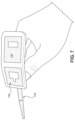
- FIGS. 6 - 7 each illustrate a hand position for holding an embodiment of the localizer.
- an embodiment of the localizer may include a main tubular body 200 .
- the main tubular body 200 may have a first terminal portion 210 and a second terminal portion 212 .
- the second terminal portion 212 may and in a flat tip 224 .
- a code platform 202 may be proximate to the first terminal portion 210 .
- the code platform 202 may have a top surface that includes one or more codes 204 , 206 and a padding 208 that surrounds and borders the respective edges of the codes 204 , 206 .
- the one or more codes 204 , 206 may be angled away from the main tubular body 200 .
- each code 204 , 206 may be a respective fiducial marker region disposed on the top surface 214 of the code platform 202 .
- the code platform 202 may be shaped according to a “V” formation such that a central portion of the code platform 202 is attached to the first terminal portion 210 and a degree amount 250 that is less than 180° exists between the fiducial marker regions on the top surface 214 .
- the degree amount 250 may be larger than 180°, to result in an “upside down V” formation.
- the code platform 202 may have a bottom surface 220 that is attached to the first terminal portion 210 .
- FIGS. 10 - 11 each illustrate a hand position for holding an embodiment of the localizer.
- FIG. 10 provides a perspective view directly above the top surface 214 of the code platform 202 resulting from the hand position for holding the localizer.
- FIG. 11 provides a perspective side view of the localizer resulting from the hand position for holding the localizer.
- an embodiment of a sheath may include a main tubular body 300 .
- the main tubular body 300 may include a first terminal portion 310 and a second terminal portion 312 .
- An arm 350 may extend perpendicularly away from the main tubular body 300 .
- the arm 350 may be attached to the main tubular body 300 proximate to the first terminal portion 310 .
- the arm 350 may be connected to a code platform 302 .
- the code platform 302 may have a top surface 314 upon which one or more codes 304 , 306 are disposed.
- the top surface 314 may have a padding 308 that surrounds the respective codes 304 , 306 and borders the respective codes 304 , 306 .
- the one or more codes 304 , 306 may be angled downwards and towards the direction of the second terminal portion 312 .
- the main tubular body 300 may include a first opening of internal passage 360 that extends from an edge of the first terminal portion 310 to an edge of the second terminal portion 312 .
- a second opening of the internal passage 360 - 1 may be included at the edge of the second terminal portion 312 .
- a degree amount 370 less than 180° exists between a first portion of the bottom surface 320 and a second portion of the bottom surface 320 .
- the degree amount 250 may be larger than 180°, whereby the code platform 302 comprises a “V” formation.
- the arm 350 connects the code platform 302 to the main tubular body 300 .
- An internal passage extends throughout and within the main tubular body 300 .
- the internal passage is accessible via openings 360 , 360 - 1 at terminal portions of the main tubular body 300 .
- the main tubular body 300 further includes a tapered tubular segment 322 and a tubular segment 326 .
- the tapered tubular segment 322 includes the flat tip 324 .
- a first diameter 328 of the tapered tubular segment 322 may be equal to a diameter of a portion of the first tubular segment 326 .
- a second diameter 330 of the tapered tubular segment 322 may be a diameter of the flat tip itself 324 .
- a particular passage opening 360 - 1 may be accessible at the flat tip 324 .
- FIG. 15 provides a perspective side view of a hand position for holding the sheath.
Landscapes
- Engineering & Computer Science (AREA)
- Health & Medical Sciences (AREA)
- Surgery (AREA)
- Life Sciences & Earth Sciences (AREA)
- Public Health (AREA)
- Veterinary Medicine (AREA)
- Biomedical Technology (AREA)
- Heart & Thoracic Surgery (AREA)
- Medical Informatics (AREA)
- Molecular Biology (AREA)
- Animal Behavior & Ethology (AREA)
- General Health & Medical Sciences (AREA)
- Nuclear Medicine, Radiotherapy & Molecular Imaging (AREA)
- Theoretical Computer Science (AREA)
- General Engineering & Computer Science (AREA)
- Robotics (AREA)
- Physics & Mathematics (AREA)
- General Physics & Mathematics (AREA)
- Human Computer Interaction (AREA)
- Multimedia (AREA)
- Computer Vision & Pattern Recognition (AREA)
- Oral & Maxillofacial Surgery (AREA)
- Pathology (AREA)
- Surgical Instruments (AREA)
Abstract
Description
Claims (14)
Priority Applications (8)
| Application Number | Priority Date | Filing Date | Title |
|---|---|---|---|
| US17/395,233 US11857274B2 (en) | 2021-01-13 | 2021-08-05 | Medical instrument with fiducial markers |
| US17/489,693 US11931114B2 (en) | 2021-03-05 | 2021-09-29 | Virtual interaction with instruments in augmented reality |
| US17/502,037 US11429247B1 (en) | 2021-03-05 | 2021-10-14 | Interactions with slices of medical data in augmented reality |
| US17/709,397 US11657247B2 (en) | 2021-08-05 | 2022-03-30 | Adhesive fiducial markers for medical augmented reality |
| US17/871,885 US11744652B2 (en) | 2021-01-13 | 2022-07-22 | Visualization of predicted dosage |
| US17/961,423 US11992934B2 (en) | 2021-01-13 | 2022-10-06 | Stereo video in augmented reality |
| US18/583,328 US20240189044A1 (en) | 2021-03-05 | 2024-02-21 | Virtual interaction with instruments in augmented reality |
| US18/672,316 US20240308086A1 (en) | 2021-01-13 | 2024-05-23 | Stereo video in augmented reality |
Applications Claiming Priority (2)
| Application Number | Priority Date | Filing Date | Title |
|---|---|---|---|
| US17/148,522 US11172996B1 (en) | 2021-01-13 | 2021-01-13 | Instrument-based registration and alignment for augmented reality environments |
| US17/395,233 US11857274B2 (en) | 2021-01-13 | 2021-08-05 | Medical instrument with fiducial markers |
Related Parent Applications (3)
| Application Number | Title | Priority Date | Filing Date |
|---|---|---|---|
| US17/148,522 Continuation-In-Part US11172996B1 (en) | 2021-01-13 | 2021-01-13 | Instrument-based registration and alignment for augmented reality environments |
| US17/194,191 Continuation-In-Part US11307653B1 (en) | 2021-01-13 | 2021-03-05 | User input and interface design in augmented reality for use in surgical settings |
| US17/502,030 Continuation-In-Part US20220218420A1 (en) | 2021-01-13 | 2021-10-14 | Instrument-based registration and alignment for augmented reality environments |
Related Child Applications (7)
| Application Number | Title | Priority Date | Filing Date |
|---|---|---|---|
| US17/194,191 Continuation-In-Part US11307653B1 (en) | 2021-01-13 | 2021-03-05 | User input and interface design in augmented reality for use in surgical settings |
| US17/502,037 Continuation-In-Part US11429247B1 (en) | 2021-03-05 | 2021-10-14 | Interactions with slices of medical data in augmented reality |
| US17/502,030 Continuation-In-Part US20220218420A1 (en) | 2021-01-13 | 2021-10-14 | Instrument-based registration and alignment for augmented reality environments |
| US17/709,397 Continuation-In-Part US11657247B2 (en) | 2021-08-05 | 2022-03-30 | Adhesive fiducial markers for medical augmented reality |
| US17/723,437 Continuation-In-Part US11656690B2 (en) | 2021-01-13 | 2022-04-18 | User input and virtual touch pad in augmented reality for use in surgical settings |
| US17/871,885 Continuation-In-Part US11744652B2 (en) | 2021-01-13 | 2022-07-22 | Visualization of predicted dosage |
| US17/961,423 Continuation-In-Part US11992934B2 (en) | 2021-01-13 | 2022-10-06 | Stereo video in augmented reality |
Publications (2)
| Publication Number | Publication Date |
|---|---|
| US20220218419A1 US20220218419A1 (en) | 2022-07-14 |
| US11857274B2 true US11857274B2 (en) | 2024-01-02 |
Family
ID=82322477
Family Applications (1)
| Application Number | Title | Priority Date | Filing Date |
|---|---|---|---|
| US17/395,233 Active US11857274B2 (en) | 2021-01-13 | 2021-08-05 | Medical instrument with fiducial markers |
Country Status (1)
| Country | Link |
|---|---|
| US (1) | US11857274B2 (en) |
Citations (11)
| Publication number | Priority date | Publication date | Assignee | Title |
|---|---|---|---|---|
| US20080228064A1 (en) | 2005-10-17 | 2008-09-18 | Koninklijke Philips Electronics N. V. | Marker Tracking for Interventional Magnetic Resonance |
| US7427272B2 (en) * | 2003-07-15 | 2008-09-23 | Orthosoft Inc. | Method for locating the mechanical axis of a femur |
| US20100002921A1 (en) | 2008-07-07 | 2010-01-07 | Matthias Fenchel | Medical image acquisition apparatus and operating method therefor |
| US20140171787A1 (en) * | 2012-12-07 | 2014-06-19 | The Methodist Hospital | Surgical procedure management systems and methods |
| US20150265367A1 (en) * | 2014-03-19 | 2015-09-24 | Ulrich Gruhler | Automatic registration of the penetration depth and the rotational orientation of an invasive instrument |
| US20180193097A1 (en) | 2017-01-11 | 2018-07-12 | Stewart David MCLACHLIN | Patient reference device |
| US20180253856A1 (en) | 2017-03-01 | 2018-09-06 | Microsoft Technology Licensing, Llc | Multi-Spectrum Illumination-and-Sensor Module for Head Tracking, Gesture Recognition and Spatial Mapping |
| US20190090955A1 (en) * | 2016-03-01 | 2019-03-28 | Mirus Llc | Systems and methods for position and orientation tracking of anatomy and surgical instruments |
| US20200005486A1 (en) | 2018-07-02 | 2020-01-02 | Microsoft Technology Licensing, Llc | Device pose estimation using 3d line clouds |
| US20200352655A1 (en) | 2019-05-06 | 2020-11-12 | ARUS Inc. | Methods, devices, and systems for augmented reality guidance of medical devices into soft tissue |
| US20210378756A1 (en) * | 2020-06-09 | 2021-12-09 | Globus Medical, Inc. | Surgical object tracking in visible light via fiducial seeding and synthetic image registration |
-
2021
- 2021-08-05 US US17/395,233 patent/US11857274B2/en active Active
Patent Citations (11)
| Publication number | Priority date | Publication date | Assignee | Title |
|---|---|---|---|---|
| US7427272B2 (en) * | 2003-07-15 | 2008-09-23 | Orthosoft Inc. | Method for locating the mechanical axis of a femur |
| US20080228064A1 (en) | 2005-10-17 | 2008-09-18 | Koninklijke Philips Electronics N. V. | Marker Tracking for Interventional Magnetic Resonance |
| US20100002921A1 (en) | 2008-07-07 | 2010-01-07 | Matthias Fenchel | Medical image acquisition apparatus and operating method therefor |
| US20140171787A1 (en) * | 2012-12-07 | 2014-06-19 | The Methodist Hospital | Surgical procedure management systems and methods |
| US20150265367A1 (en) * | 2014-03-19 | 2015-09-24 | Ulrich Gruhler | Automatic registration of the penetration depth and the rotational orientation of an invasive instrument |
| US20190090955A1 (en) * | 2016-03-01 | 2019-03-28 | Mirus Llc | Systems and methods for position and orientation tracking of anatomy and surgical instruments |
| US20180193097A1 (en) | 2017-01-11 | 2018-07-12 | Stewart David MCLACHLIN | Patient reference device |
| US20180253856A1 (en) | 2017-03-01 | 2018-09-06 | Microsoft Technology Licensing, Llc | Multi-Spectrum Illumination-and-Sensor Module for Head Tracking, Gesture Recognition and Spatial Mapping |
| US20200005486A1 (en) | 2018-07-02 | 2020-01-02 | Microsoft Technology Licensing, Llc | Device pose estimation using 3d line clouds |
| US20200352655A1 (en) | 2019-05-06 | 2020-11-12 | ARUS Inc. | Methods, devices, and systems for augmented reality guidance of medical devices into soft tissue |
| US20210378756A1 (en) * | 2020-06-09 | 2021-12-09 | Globus Medical, Inc. | Surgical object tracking in visible light via fiducial seeding and synthetic image registration |
Also Published As
| Publication number | Publication date |
|---|---|
| US20220218419A1 (en) | 2022-07-14 |
Similar Documents
| Publication | Publication Date | Title |
|---|---|---|
| US11717376B2 (en) | System and method for dynamic validation, correction of registration misalignment for surgical navigation between the real and virtual images | |
| US11269401B2 (en) | System and method for holographic image-guided non-vascular percutaneous procedures | |
| US9248000B2 (en) | System for and method of visualizing an interior of body | |
| US20210259785A1 (en) | System and method for mapping navigation space to patient space in a medical procedure | |
| US5836954A (en) | Apparatus and method for photogrammetric surgical localization | |
| US10166078B2 (en) | System and method for mapping navigation space to patient space in a medical procedure | |
| WO2019217795A4 (en) | Live 3d holographic guidance and navigation for performing interventional procedures | |
| CN111970986A (en) | System and method for performing intraoperative guidance | |
| US20060036162A1 (en) | Method and apparatus for guiding a medical instrument to a subsurface target site in a patient | |
| WO2012149548A2 (en) | System and method for tracking and navigation | |
| US11857274B2 (en) | Medical instrument with fiducial markers | |
| Colchester et al. | Craniotomy simulation and guidance using a stereo video based tracking system (VISLAN) | |
| US11657247B2 (en) | Adhesive fiducial markers for medical augmented reality | |
| US11389250B2 (en) | Position detection system by fiber Bragg grating based optical sensors in surgical fields | |
| CN115486937A (en) | 2D image surgical positioning navigation system and method |
Legal Events
| Date | Code | Title | Description |
|---|---|---|---|
| AS | Assignment |
Owner name: MEDIVIS, INC., NEW YORK Free format text: ASSIGNMENT OF ASSIGNORS INTEREST;ASSIGNORS:QIAN, LONG;MORLEY, CHRISTOPHER;CHOUDHRY, OSAMAH;SIGNING DATES FROM 20210108 TO 20210111;REEL/FRAME:057097/0305 |
|
| FEPP | Fee payment procedure |
Free format text: ENTITY STATUS SET TO UNDISCOUNTED (ORIGINAL EVENT CODE: BIG.); ENTITY STATUS OF PATENT OWNER: SMALL ENTITY |
|
| FEPP | Fee payment procedure |
Free format text: ENTITY STATUS SET TO SMALL (ORIGINAL EVENT CODE: SMAL); ENTITY STATUS OF PATENT OWNER: SMALL ENTITY |
|
| STPP | Information on status: patent application and granting procedure in general |
Free format text: RESPONSE TO NON-FINAL OFFICE ACTION ENTERED AND FORWARDED TO EXAMINER |
|
| STPP | Information on status: patent application and granting procedure in general |
Free format text: FINAL REJECTION MAILED |
|
| STPP | Information on status: patent application and granting procedure in general |
Free format text: DOCKETED NEW CASE - READY FOR EXAMINATION |
|
| STPP | Information on status: patent application and granting procedure in general |
Free format text: NON FINAL ACTION MAILED |
|
| STPP | Information on status: patent application and granting procedure in general |
Free format text: RESPONSE TO NON-FINAL OFFICE ACTION ENTERED AND FORWARDED TO EXAMINER |
|
| STPP | Information on status: patent application and granting procedure in general |
Free format text: NOTICE OF ALLOWANCE MAILED -- APPLICATION RECEIVED IN OFFICE OF PUBLICATIONS |
|
| STPP | Information on status: patent application and granting procedure in general |
Free format text: PUBLICATIONS -- ISSUE FEE PAYMENT RECEIVED |
|
| STPP | Information on status: patent application and granting procedure in general |
Free format text: PUBLICATIONS -- ISSUE FEE PAYMENT VERIFIED |
|
| STCF | Information on status: patent grant |
Free format text: PATENTED CASE |