US11856844B2 - Organic electroluminescence device and amine compound for organic electroluminescence device - Google Patents
Organic electroluminescence device and amine compound for organic electroluminescence device Download PDFInfo
- Publication number
- US11856844B2 US11856844B2 US17/080,732 US202017080732A US11856844B2 US 11856844 B2 US11856844 B2 US 11856844B2 US 202017080732 A US202017080732 A US 202017080732A US 11856844 B2 US11856844 B2 US 11856844B2
- Authority
- US
- United States
- Prior art keywords
- group
- formula
- substituted
- ring
- carbon atoms
- Prior art date
- Legal status (The legal status is an assumption and is not a legal conclusion. Google has not performed a legal analysis and makes no representation as to the accuracy of the status listed.)
- Active, expires
Links
- -1 amine compound Chemical class 0.000 title claims abstract description 160
- 238000005401 electroluminescence Methods 0.000 title claims abstract description 65
- 125000004432 carbon atom Chemical group C* 0.000 claims abstract description 70
- 125000003118 aryl group Chemical group 0.000 claims abstract description 51
- 125000001072 heteroaryl group Chemical group 0.000 claims abstract description 40
- 125000003983 fluorenyl group Chemical group C1(=CC=CC=2C3=CC=CC=C3CC12)* 0.000 claims abstract description 36
- 229910052805 deuterium Inorganic materials 0.000 claims abstract description 35
- YZCKVEUIGOORGS-OUBTZVSYSA-N Deuterium Chemical group [2H] YZCKVEUIGOORGS-OUBTZVSYSA-N 0.000 claims abstract description 28
- 125000003277 amino group Chemical group 0.000 claims abstract description 21
- 239000012044 organic layer Substances 0.000 claims abstract description 21
- 239000010410 layer Substances 0.000 claims description 138
- 150000001875 compounds Chemical class 0.000 claims description 75
- 230000005525 hole transport Effects 0.000 claims description 55
- 238000002347 injection Methods 0.000 claims description 30
- 239000007924 injection Substances 0.000 claims description 30
- 125000001997 phenyl group Chemical group [H]C1=C([H])C([H])=C(*)C([H])=C1[H] 0.000 claims description 18
- 125000000217 alkyl group Chemical group 0.000 claims description 17
- 125000005843 halogen group Chemical group 0.000 claims description 13
- 125000004435 hydrogen atom Chemical group [H]* 0.000 claims description 13
- 125000006267 biphenyl group Chemical group 0.000 claims description 12
- 125000001624 naphthyl group Chemical group 0.000 claims description 10
- 125000000732 arylene group Chemical group 0.000 claims description 7
- 150000001975 deuterium Chemical group 0.000 claims description 7
- 125000005549 heteroarylene group Chemical group 0.000 claims description 7
- 229910052760 oxygen Inorganic materials 0.000 claims description 7
- 229910052717 sulfur Inorganic materials 0.000 claims description 7
- IYYZUPMFVPLQIF-ALWQSETLSA-N dibenzothiophene Chemical group C1=CC=CC=2[34S]C3=C(C=21)C=CC=C3 IYYZUPMFVPLQIF-ALWQSETLSA-N 0.000 claims description 6
- TXCDCPKCNAJMEE-UHFFFAOYSA-N dibenzofuran Chemical group C1=CC=C2C3=CC=CC=C3OC2=C1 TXCDCPKCNAJMEE-UHFFFAOYSA-N 0.000 claims description 5
- 125000000609 carbazolyl group Chemical group C1(=CC=CC=2C3=CC=CC=C3NC12)* 0.000 claims description 3
- 239000000463 material Substances 0.000 description 44
- 238000000034 method Methods 0.000 description 29
- 230000000052 comparative effect Effects 0.000 description 22
- 230000015572 biosynthetic process Effects 0.000 description 14
- 125000001424 substituent group Chemical group 0.000 description 14
- 238000003786 synthesis reaction Methods 0.000 description 14
- 125000000623 heterocyclic group Chemical group 0.000 description 13
- 239000002356 single layer Substances 0.000 description 12
- 239000002019 doping agent Substances 0.000 description 11
- 230000000903 blocking effect Effects 0.000 description 10
- 238000010189 synthetic method Methods 0.000 description 10
- 150000002430 hydrocarbons Chemical group 0.000 description 9
- 229910052751 metal Inorganic materials 0.000 description 9
- 239000002184 metal Substances 0.000 description 9
- OKTJSMMVPCPJKN-UHFFFAOYSA-N Carbon Chemical compound [C] OKTJSMMVPCPJKN-UHFFFAOYSA-N 0.000 description 8
- 239000007983 Tris buffer Substances 0.000 description 8
- 229910052799 carbon Inorganic materials 0.000 description 8
- WYURNTSHIVDZCO-UHFFFAOYSA-N Tetrahydrofuran Chemical group C1CCOC1 WYURNTSHIVDZCO-UHFFFAOYSA-N 0.000 description 7
- XLOMVQKBTHCTTD-UHFFFAOYSA-N Zinc monoxide Chemical compound [Zn]=O XLOMVQKBTHCTTD-UHFFFAOYSA-N 0.000 description 7
- 239000000872 buffer Substances 0.000 description 7
- 239000000203 mixture Substances 0.000 description 7
- BASFCYQUMIYNBI-UHFFFAOYSA-N platinum Chemical compound [Pt] BASFCYQUMIYNBI-UHFFFAOYSA-N 0.000 description 7
- BCFCTTHZFYZOHT-ONEGZZNKSA-N (e)-1-bromo-2-ethoxyethene Chemical compound CCO\C=C\Br BCFCTTHZFYZOHT-ONEGZZNKSA-N 0.000 description 6
- RTZKZFJDLAIYFH-UHFFFAOYSA-N Diethyl ether Chemical compound CCOCC RTZKZFJDLAIYFH-UHFFFAOYSA-N 0.000 description 6
- KDLHZDBZIXYQEI-UHFFFAOYSA-N Palladium Chemical compound [Pd] KDLHZDBZIXYQEI-UHFFFAOYSA-N 0.000 description 6
- 229910052782 aluminium Inorganic materials 0.000 description 6
- 238000004519 manufacturing process Methods 0.000 description 6
- 229920000767 polyaniline Polymers 0.000 description 6
- 125000003367 polycyclic group Chemical group 0.000 description 6
- XNLBCXGRQWUJLU-GSNKEKJESA-N C1(=C(C(=C(C2=C(C(=C(C(=C12)[2H])[2H])[2H])[2H])[2H])[2H])C(=O)Cl)[2H] Chemical compound C1(=C(C(=C(C2=C(C(=C(C(=C12)[2H])[2H])[2H])[2H])[2H])[2H])C(=O)Cl)[2H] XNLBCXGRQWUJLU-GSNKEKJESA-N 0.000 description 5
- 239000011575 calcium Substances 0.000 description 5
- DMBHHRLKUKUOEG-UHFFFAOYSA-N diphenylamine Chemical group C=1C=CC=CC=1NC1=CC=CC=C1 DMBHHRLKUKUOEG-UHFFFAOYSA-N 0.000 description 5
- 125000005842 heteroatom Chemical group 0.000 description 5
- 229910052741 iridium Inorganic materials 0.000 description 5
- 239000011777 magnesium Substances 0.000 description 5
- 229910044991 metal oxide Inorganic materials 0.000 description 5
- 150000004706 metal oxides Chemical class 0.000 description 5
- 229910052757 nitrogen Inorganic materials 0.000 description 5
- 239000010936 titanium Substances 0.000 description 5
- TVIVIEFSHFOWTE-UHFFFAOYSA-K tri(quinolin-8-yloxy)alumane Chemical compound [Al+3].C1=CN=C2C([O-])=CC=CC2=C1.C1=CN=C2C([O-])=CC=CC2=C1.C1=CN=C2C([O-])=CC=CC2=C1 TVIVIEFSHFOWTE-UHFFFAOYSA-K 0.000 description 5
- XLYOFNOQVPJJNP-UHFFFAOYSA-N water Chemical compound O XLYOFNOQVPJJNP-UHFFFAOYSA-N 0.000 description 5
- AWXGSYPUMWKTBR-UHFFFAOYSA-N 4-carbazol-9-yl-n,n-bis(4-carbazol-9-ylphenyl)aniline Chemical compound C12=CC=CC=C2C2=CC=CC=C2N1C1=CC=C(N(C=2C=CC(=CC=2)N2C3=CC=CC=C3C3=CC=CC=C32)C=2C=CC(=CC=2)N2C3=CC=CC=C3C3=CC=CC=C32)C=C1 AWXGSYPUMWKTBR-UHFFFAOYSA-N 0.000 description 4
- VFUDMQLBKNMONU-UHFFFAOYSA-N 9-[4-(4-carbazol-9-ylphenyl)phenyl]carbazole Chemical group C12=CC=CC=C2C2=CC=CC=C2N1C1=CC=C(C=2C=CC(=CC=2)N2C3=CC=CC=C3C3=CC=CC=C32)C=C1 VFUDMQLBKNMONU-UHFFFAOYSA-N 0.000 description 4
- JQUCWIWWWKZNCS-LESHARBVSA-N C(C1=CC=CC=C1)(=O)NC=1SC[C@H]2[C@@](N1)(CO[C@H](C2)C)C=2SC=C(N2)NC(=O)C2=NC=C(C=C2)OC(F)F Chemical compound C(C1=CC=CC=C1)(=O)NC=1SC[C@H]2[C@@](N1)(CO[C@H](C2)C)C=2SC=C(N2)NC(=O)C2=NC=C(C=C2)OC(F)F JQUCWIWWWKZNCS-LESHARBVSA-N 0.000 description 4
- PXHVJJICTQNCMI-UHFFFAOYSA-N Nickel Chemical compound [Ni] PXHVJJICTQNCMI-UHFFFAOYSA-N 0.000 description 4
- XAGFODPZIPBFFR-UHFFFAOYSA-N aluminium Chemical compound [Al] XAGFODPZIPBFFR-UHFFFAOYSA-N 0.000 description 4
- 150000001716 carbazoles Chemical group 0.000 description 4
- 150000004696 coordination complex Chemical class 0.000 description 4
- GOXNHPQCCUVWRO-UHFFFAOYSA-N dibenzothiophen-4-ylboronic acid Chemical compound C12=CC=CC=C2SC2=C1C=CC=C2B(O)O GOXNHPQCCUVWRO-UHFFFAOYSA-N 0.000 description 4
- NIHNNTQXNPWCJQ-UHFFFAOYSA-N fluorene Chemical compound C1=CC=C2CC3=CC=CC=C3C2=C1 NIHNNTQXNPWCJQ-UHFFFAOYSA-N 0.000 description 4
- 239000010931 gold Substances 0.000 description 4
- GKOZUEZYRPOHIO-UHFFFAOYSA-N iridium atom Chemical compound [Ir] GKOZUEZYRPOHIO-UHFFFAOYSA-N 0.000 description 4
- 229910052749 magnesium Inorganic materials 0.000 description 4
- 125000002950 monocyclic group Chemical group 0.000 description 4
- 229910052709 silver Inorganic materials 0.000 description 4
- DFRAKBCRUYUFNT-UHFFFAOYSA-N 3,8-dicyclohexyl-2,4,7,9-tetrahydro-[1,3]oxazino[5,6-h][1,3]benzoxazine Chemical compound C1CCCCC1N1CC(C=CC2=C3OCN(C2)C2CCCCC2)=C3OC1 DFRAKBCRUYUFNT-UHFFFAOYSA-N 0.000 description 3
- VIZUPBYFLORCRA-UHFFFAOYSA-N 9,10-dinaphthalen-2-ylanthracene Chemical compound C12=CC=CC=C2C(C2=CC3=CC=CC=C3C=C2)=C(C=CC=C2)C2=C1C1=CC=C(C=CC=C2)C2=C1 VIZUPBYFLORCRA-UHFFFAOYSA-N 0.000 description 3
- UHOVQNZJYSORNB-UHFFFAOYSA-N Benzene Chemical compound C1=CC=CC=C1 UHOVQNZJYSORNB-UHFFFAOYSA-N 0.000 description 3
- KFZMGEQAYNKOFK-UHFFFAOYSA-N Isopropanol Chemical compound CC(C)O KFZMGEQAYNKOFK-UHFFFAOYSA-N 0.000 description 3
- CSNNHWWHGAXBCP-UHFFFAOYSA-L Magnesium sulfate Chemical compound [Mg+2].[O-][S+2]([O-])([O-])[O-] CSNNHWWHGAXBCP-UHFFFAOYSA-L 0.000 description 3
- YXFVVABEGXRONW-UHFFFAOYSA-N Toluene Chemical compound CC1=CC=CC=C1 YXFVVABEGXRONW-UHFFFAOYSA-N 0.000 description 3
- 125000001931 aliphatic group Chemical group 0.000 description 3
- 125000003342 alkenyl group Chemical group 0.000 description 3
- 125000003282 alkyl amino group Chemical group 0.000 description 3
- 125000002490 anilino group Chemical group [H]N(*)C1=C([H])C([H])=C([H])C([H])=C1[H] 0.000 description 3
- 150000001454 anthracenes Chemical class 0.000 description 3
- XRWSZZJLZRKHHD-WVWIJVSJSA-N asunaprevir Chemical compound O=C([C@@H]1C[C@H](CN1C(=O)[C@@H](NC(=O)OC(C)(C)C)C(C)(C)C)OC1=NC=C(C2=CC=C(Cl)C=C21)OC)N[C@]1(C(=O)NS(=O)(=O)C2CC2)C[C@H]1C=C XRWSZZJLZRKHHD-WVWIJVSJSA-N 0.000 description 3
- 125000004429 atom Chemical group 0.000 description 3
- 238000006243 chemical reaction Methods 0.000 description 3
- 239000011651 chromium Substances 0.000 description 3
- 238000004440 column chromatography Methods 0.000 description 3
- 229940125961 compound 24 Drugs 0.000 description 3
- 239000010949 copper Substances 0.000 description 3
- 238000011156 evaluation Methods 0.000 description 3
- 125000000524 functional group Chemical group 0.000 description 3
- 239000011521 glass Substances 0.000 description 3
- 239000002346 layers by function Substances 0.000 description 3
- 238000012986 modification Methods 0.000 description 3
- 230000004048 modification Effects 0.000 description 3
- IBHBKWKFFTZAHE-UHFFFAOYSA-N n-[4-[4-(n-naphthalen-1-ylanilino)phenyl]phenyl]-n-phenylnaphthalen-1-amine Chemical compound C1=CC=CC=C1N(C=1C2=CC=CC=C2C=CC=1)C1=CC=C(C=2C=CC(=CC=2)N(C=2C=CC=CC=2)C=2C3=CC=CC=C3C=CC=2)C=C1 IBHBKWKFFTZAHE-UHFFFAOYSA-N 0.000 description 3
- 125000004433 nitrogen atom Chemical group N* 0.000 description 3
- 150000002902 organometallic compounds Chemical class 0.000 description 3
- 125000002080 perylenyl group Chemical group C1(=CC=C2C=CC=C3C4=CC=CC5=CC=CC(C1=C23)=C45)* 0.000 description 3
- CSHWQDPOILHKBI-UHFFFAOYSA-N peryrene Natural products C1=CC(C2=CC=CC=3C2=C2C=CC=3)=C3C2=CC=CC3=C1 CSHWQDPOILHKBI-UHFFFAOYSA-N 0.000 description 3
- 229910052697 platinum Inorganic materials 0.000 description 3
- 229920003227 poly(N-vinyl carbazole) Polymers 0.000 description 3
- 150000003839 salts Chemical class 0.000 description 3
- 239000000243 solution Substances 0.000 description 3
- 239000000758 substrate Substances 0.000 description 3
- 229910052719 titanium Inorganic materials 0.000 description 3
- ODHXBMXNKOYIBV-UHFFFAOYSA-N triphenylamine Chemical compound C1=CC=CC=C1N(C=1C=CC=CC=1)C1=CC=CC=C1 ODHXBMXNKOYIBV-UHFFFAOYSA-N 0.000 description 3
- 238000001771 vacuum deposition Methods 0.000 description 3
- 125000000391 vinyl group Chemical group [H]C([*])=C([H])[H] 0.000 description 3
- 239000011787 zinc oxide Substances 0.000 description 3
- POILWHVDKZOXJZ-ARJAWSKDSA-M (z)-4-oxopent-2-en-2-olate Chemical compound C\C([O-])=C\C(C)=O POILWHVDKZOXJZ-ARJAWSKDSA-M 0.000 description 2
- NGQSLSMAEVWNPU-YTEMWHBBSA-N 1,2-bis[(e)-2-phenylethenyl]benzene Chemical compound C=1C=CC=CC=1/C=C/C1=CC=CC=C1\C=C\C1=CC=CC=C1 NGQSLSMAEVWNPU-YTEMWHBBSA-N 0.000 description 2
- ATTVYRDSOVWELU-UHFFFAOYSA-N 1-diphenylphosphoryl-2-(2-diphenylphosphorylphenoxy)benzene Chemical compound C=1C=CC=CC=1P(C=1C(=CC=CC=1)OC=1C(=CC=CC=1)P(=O)(C=1C=CC=CC=1)C=1C=CC=CC=1)(=O)C1=CC=CC=C1 ATTVYRDSOVWELU-UHFFFAOYSA-N 0.000 description 2
- IYZMXHQDXZKNCY-UHFFFAOYSA-N 1-n,1-n-diphenyl-4-n,4-n-bis[4-(n-phenylanilino)phenyl]benzene-1,4-diamine Chemical compound C1=CC=CC=C1N(C=1C=CC(=CC=1)N(C=1C=CC(=CC=1)N(C=1C=CC=CC=1)C=1C=CC=CC=1)C=1C=CC(=CC=1)N(C=1C=CC=CC=1)C=1C=CC=CC=1)C1=CC=CC=C1 IYZMXHQDXZKNCY-UHFFFAOYSA-N 0.000 description 2
- 238000005160 1H NMR spectroscopy Methods 0.000 description 2
- VFMUXPQZKOKPOF-UHFFFAOYSA-N 2,3,7,8,12,13,17,18-octaethyl-21,23-dihydroporphyrin platinum Chemical compound [Pt].CCc1c(CC)c2cc3[nH]c(cc4nc(cc5[nH]c(cc1n2)c(CC)c5CC)c(CC)c4CC)c(CC)c3CC VFMUXPQZKOKPOF-UHFFFAOYSA-N 0.000 description 2
- AIAJGVRFXREWPK-UHFFFAOYSA-N 2,8-bis(diphenylphosphoryl)dibenzofuran Chemical compound C=1C=CC=CC=1P(C=1C=C2C3=CC(=CC=C3OC2=CC=1)P(=O)(C=1C=CC=CC=1)C=1C=CC=CC=1)(=O)C1=CC=CC=C1 AIAJGVRFXREWPK-UHFFFAOYSA-N 0.000 description 2
- STTGYIUESPWXOW-UHFFFAOYSA-N 2,9-dimethyl-4,7-diphenyl-1,10-phenanthroline Chemical compound C=12C=CC3=C(C=4C=CC=CC=4)C=C(C)N=C3C2=NC(C)=CC=1C1=CC=CC=C1 STTGYIUESPWXOW-UHFFFAOYSA-N 0.000 description 2
- GEQBRULPNIVQPP-UHFFFAOYSA-N 2-[3,5-bis(1-phenylbenzimidazol-2-yl)phenyl]-1-phenylbenzimidazole Chemical compound C1=CC=CC=C1N1C2=CC=CC=C2N=C1C1=CC(C=2N(C3=CC=CC=C3N=2)C=2C=CC=CC=2)=CC(C=2N(C3=CC=CC=C3N=2)C=2C=CC=CC=2)=C1 GEQBRULPNIVQPP-UHFFFAOYSA-N 0.000 description 2
- IXHWGNYCZPISET-UHFFFAOYSA-N 2-[4-(dicyanomethylidene)-2,3,5,6-tetrafluorocyclohexa-2,5-dien-1-ylidene]propanedinitrile Chemical compound FC1=C(F)C(=C(C#N)C#N)C(F)=C(F)C1=C(C#N)C#N IXHWGNYCZPISET-UHFFFAOYSA-N 0.000 description 2
- HNWFFTUWRIGBNM-UHFFFAOYSA-N 2-methyl-9,10-dinaphthalen-2-ylanthracene Chemical compound C1=CC=CC2=CC(C3=C4C=CC=CC4=C(C=4C=C5C=CC=CC5=CC=4)C4=CC=C(C=C43)C)=CC=C21 HNWFFTUWRIGBNM-UHFFFAOYSA-N 0.000 description 2
- OBAJPWYDYFEBTF-UHFFFAOYSA-N 2-tert-butyl-9,10-dinaphthalen-2-ylanthracene Chemical compound C1=CC=CC2=CC(C3=C4C=CC=CC4=C(C=4C=C5C=CC=CC5=CC=4)C4=CC=C(C=C43)C(C)(C)C)=CC=C21 OBAJPWYDYFEBTF-UHFFFAOYSA-N 0.000 description 2
- ZVFQEOPUXVPSLB-UHFFFAOYSA-N 3-(4-tert-butylphenyl)-4-phenyl-5-(4-phenylphenyl)-1,2,4-triazole Chemical compound C1=CC(C(C)(C)C)=CC=C1C(N1C=2C=CC=CC=2)=NN=C1C1=CC=C(C=2C=CC=CC=2)C=C1 ZVFQEOPUXVPSLB-UHFFFAOYSA-N 0.000 description 2
- DHDHJYNTEFLIHY-UHFFFAOYSA-N 4,7-diphenyl-1,10-phenanthroline Chemical compound C1=CC=CC=C1C1=CC=NC2=C1C=CC1=C(C=3C=CC=CC=3)C=CN=C21 DHDHJYNTEFLIHY-UHFFFAOYSA-N 0.000 description 2
- OSQXTXTYKAEHQV-WXUKJITCSA-N 4-methyl-n-[4-[(e)-2-[4-[4-[(e)-2-[4-(4-methyl-n-(4-methylphenyl)anilino)phenyl]ethenyl]phenyl]phenyl]ethenyl]phenyl]-n-(4-methylphenyl)aniline Chemical compound C1=CC(C)=CC=C1N(C=1C=CC(\C=C\C=2C=CC(=CC=2)C=2C=CC(\C=C\C=3C=CC(=CC=3)N(C=3C=CC(C)=CC=3)C=3C=CC(C)=CC=3)=CC=2)=CC=1)C1=CC=C(C)C=C1 OSQXTXTYKAEHQV-WXUKJITCSA-N 0.000 description 2
- ZOKIJILZFXPFTO-UHFFFAOYSA-N 4-methyl-n-[4-[1-[4-(4-methyl-n-(4-methylphenyl)anilino)phenyl]cyclohexyl]phenyl]-n-(4-methylphenyl)aniline Chemical compound C1=CC(C)=CC=C1N(C=1C=CC(=CC=1)C1(CCCCC1)C=1C=CC(=CC=1)N(C=1C=CC(C)=CC=1)C=1C=CC(C)=CC=1)C1=CC=C(C)C=C1 ZOKIJILZFXPFTO-UHFFFAOYSA-N 0.000 description 2
- DIVZFUBWFAOMCW-UHFFFAOYSA-N 4-n-(3-methylphenyl)-1-n,1-n-bis[4-(n-(3-methylphenyl)anilino)phenyl]-4-n-phenylbenzene-1,4-diamine Chemical compound CC1=CC=CC(N(C=2C=CC=CC=2)C=2C=CC(=CC=2)N(C=2C=CC(=CC=2)N(C=2C=CC=CC=2)C=2C=C(C)C=CC=2)C=2C=CC(=CC=2)N(C=2C=CC=CC=2)C=2C=C(C)C=CC=2)=C1 DIVZFUBWFAOMCW-UHFFFAOYSA-N 0.000 description 2
- AOQKGYRILLEVJV-UHFFFAOYSA-N 4-naphthalen-1-yl-3,5-diphenyl-1,2,4-triazole Chemical compound C1=CC=CC=C1C(N1C=2C3=CC=CC=C3C=CC=2)=NN=C1C1=CC=CC=C1 AOQKGYRILLEVJV-UHFFFAOYSA-N 0.000 description 2
- MZYDBGLUVPLRKR-UHFFFAOYSA-N 9-(3-carbazol-9-ylphenyl)carbazole Chemical compound C12=CC=CC=C2C2=CC=CC=C2N1C1=CC(N2C3=CC=CC=C3C3=CC=CC=C32)=CC=C1 MZYDBGLUVPLRKR-UHFFFAOYSA-N 0.000 description 2
- LTUJKAYZIMMJEP-UHFFFAOYSA-N 9-[4-(4-carbazol-9-yl-2-methylphenyl)-3-methylphenyl]carbazole Chemical group C12=CC=CC=C2C2=CC=CC=C2N1C1=CC=C(C=2C(=CC(=CC=2)N2C3=CC=CC=C3C3=CC=CC=C32)C)C(C)=C1 LTUJKAYZIMMJEP-UHFFFAOYSA-N 0.000 description 2
- UJOBWOGCFQCDNV-UHFFFAOYSA-N 9H-carbazole Chemical group C1=CC=C2C3=CC=CC=C3NC2=C1 UJOBWOGCFQCDNV-UHFFFAOYSA-N 0.000 description 2
- IJGRMHOSHXDMSA-UHFFFAOYSA-N Atomic nitrogen Chemical compound N#N IJGRMHOSHXDMSA-UHFFFAOYSA-N 0.000 description 2
- ZOXJGFHDIHLPTG-UHFFFAOYSA-N Boron Chemical group [B] ZOXJGFHDIHLPTG-UHFFFAOYSA-N 0.000 description 2
- SCJNYBYSTCRPAO-LXBQGUBHSA-N CN(C)C\C=C\C(=O)NC1=CC=C(N=C1)C(=O)N[C@@]1(C)CCC[C@H](C1)NC1=NC(C2=CNC3=CC=CC=C23)=C(Cl)C=N1 Chemical compound CN(C)C\C=C\C(=O)NC1=CC=C(N=C1)C(=O)N[C@@]1(C)CCC[C@H](C1)NC1=NC(C2=CNC3=CC=CC=C23)=C(Cl)C=N1 SCJNYBYSTCRPAO-LXBQGUBHSA-N 0.000 description 2
- 229910052693 Europium Inorganic materials 0.000 description 2
- 101000837344 Homo sapiens T-cell leukemia translocation-altered gene protein Proteins 0.000 description 2
- 229910052779 Neodymium Inorganic materials 0.000 description 2
- CTQNGGLPUBDAKN-UHFFFAOYSA-N O-Xylene Chemical compound CC1=CC=CC=C1C CTQNGGLPUBDAKN-UHFFFAOYSA-N 0.000 description 2
- 229920001609 Poly(3,4-ethylenedioxythiophene) Polymers 0.000 description 2
- FAPWRFPIFSIZLT-UHFFFAOYSA-M Sodium chloride Chemical compound [Na+].[Cl-] FAPWRFPIFSIZLT-UHFFFAOYSA-M 0.000 description 2
- 102100028692 T-cell leukemia translocation-altered gene protein Human genes 0.000 description 2
- 101150088517 TCTA gene Proteins 0.000 description 2
- RTAQQCXQSZGOHL-UHFFFAOYSA-N Titanium Chemical compound [Ti] RTAQQCXQSZGOHL-UHFFFAOYSA-N 0.000 description 2
- DGEZNRSVGBDHLK-UHFFFAOYSA-N [1,10]phenanthroline Chemical compound C1=CN=C2C3=NC=CC=C3C=CC2=C1 DGEZNRSVGBDHLK-UHFFFAOYSA-N 0.000 description 2
- CUJRVFIICFDLGR-UHFFFAOYSA-N acetylacetonate Chemical compound CC(=O)[CH-]C(C)=O CUJRVFIICFDLGR-UHFFFAOYSA-N 0.000 description 2
- 150000001338 aliphatic hydrocarbons Chemical group 0.000 description 2
- 150000001412 amines Chemical class 0.000 description 2
- MWPLVEDNUUSJAV-UHFFFAOYSA-N anthracene Chemical compound C1=CC=CC2=CC3=CC=CC=C3C=C21 MWPLVEDNUUSJAV-UHFFFAOYSA-N 0.000 description 2
- 125000006615 aromatic heterocyclic group Chemical group 0.000 description 2
- 150000004945 aromatic hydrocarbons Chemical group 0.000 description 2
- 125000005264 aryl amine group Chemical group 0.000 description 2
- JDOBIJWMPMUWNO-UHFFFAOYSA-N bis(4-carbazol-9-ylphenyl)-diphenylsilane Chemical compound C1=CC=CC=C1[Si](C=1C=CC(=CC=1)N1C2=CC=CC=C2C2=CC=CC=C21)(C=1C=CC(=CC=1)N1C2=CC=CC=C2C2=CC=CC=C21)C1=CC=CC=C1 JDOBIJWMPMUWNO-UHFFFAOYSA-N 0.000 description 2
- UFVXQDWNSAGPHN-UHFFFAOYSA-K bis[(2-methylquinolin-8-yl)oxy]-(4-phenylphenoxy)alumane Chemical compound [Al+3].C1=CC=C([O-])C2=NC(C)=CC=C21.C1=CC=C([O-])C2=NC(C)=CC=C21.C1=CC([O-])=CC=C1C1=CC=CC=C1 UFVXQDWNSAGPHN-UHFFFAOYSA-K 0.000 description 2
- 229910052804 chromium Inorganic materials 0.000 description 2
- 229910052802 copper Inorganic materials 0.000 description 2
- 125000004093 cyano group Chemical group *C#N 0.000 description 2
- ZXHUJRZYLRVVNP-UHFFFAOYSA-N dibenzofuran-4-ylboronic acid Chemical compound C12=CC=CC=C2OC2=C1C=CC=C2B(O)O ZXHUJRZYLRVVNP-UHFFFAOYSA-N 0.000 description 2
- 125000002147 dimethylamino group Chemical group [H]C([H])([H])N(*)C([H])([H])[H] 0.000 description 2
- ZUOUZKKEUPVFJK-UHFFFAOYSA-N diphenyl Chemical compound C1=CC=CC=C1C1=CC=CC=C1 ZUOUZKKEUPVFJK-UHFFFAOYSA-N 0.000 description 2
- 125000001495 ethyl group Chemical group [H]C([H])([H])C([H])([H])* 0.000 description 2
- OGPBJKLSAFTDLK-UHFFFAOYSA-N europium atom Chemical compound [Eu] OGPBJKLSAFTDLK-UHFFFAOYSA-N 0.000 description 2
- 150000002220 fluorenes Chemical group 0.000 description 2
- PCHJSUWPFVWCPO-UHFFFAOYSA-N gold Chemical compound [Au] PCHJSUWPFVWCPO-UHFFFAOYSA-N 0.000 description 2
- 229910052737 gold Inorganic materials 0.000 description 2
- 238000007641 inkjet printing Methods 0.000 description 2
- UEEXRMUCXBPYOV-UHFFFAOYSA-N iridium;2-phenylpyridine Chemical compound [Ir].C1=CC=CC=C1C1=CC=CC=N1.C1=CC=CC=C1C1=CC=CC=N1.C1=CC=CC=C1C1=CC=CC=N1 UEEXRMUCXBPYOV-UHFFFAOYSA-N 0.000 description 2
- 238000007648 laser printing Methods 0.000 description 2
- 229910001507 metal halide Inorganic materials 0.000 description 2
- 150000005309 metal halides Chemical class 0.000 description 2
- 125000002496 methyl group Chemical group [H]C([H])([H])* 0.000 description 2
- 125000000250 methylamino group Chemical group [H]N(*)C([H])([H])[H] 0.000 description 2
- 229910052750 molybdenum Inorganic materials 0.000 description 2
- YPJRZWDWVBNDIW-MBALSZOMSA-N n,n-diphenyl-4-[(e)-2-[4-[4-[(e)-2-[4-(n-phenylanilino)phenyl]ethenyl]phenyl]phenyl]ethenyl]aniline Chemical group C=1C=C(N(C=2C=CC=CC=2)C=2C=CC=CC=2)C=CC=1/C=C/C(C=C1)=CC=C1C(C=C1)=CC=C1\C=C\C(C=C1)=CC=C1N(C=1C=CC=CC=1)C1=CC=CC=C1 YPJRZWDWVBNDIW-MBALSZOMSA-N 0.000 description 2
- 125000005184 naphthylamino group Chemical group C1(=CC=CC2=CC=CC=C12)N* 0.000 description 2
- 229910052759 nickel Inorganic materials 0.000 description 2
- 125000001715 oxadiazolyl group Chemical group 0.000 description 2
- 229910052763 palladium Inorganic materials 0.000 description 2
- 229920000553 poly(phenylenevinylene) Polymers 0.000 description 2
- 229920002098 polyfluorene Polymers 0.000 description 2
- 229920000642 polymer Polymers 0.000 description 2
- BWHMMNNQKKPAPP-UHFFFAOYSA-L potassium carbonate Chemical compound [K+].[K+].[O-]C([O-])=O BWHMMNNQKKPAPP-UHFFFAOYSA-L 0.000 description 2
- BBEAQIROQSPTKN-UHFFFAOYSA-N pyrene Chemical compound C1=CC=C2C=CC3=CC=CC4=CC=C1C2=C43 BBEAQIROQSPTKN-UHFFFAOYSA-N 0.000 description 2
- 150000003220 pyrenes Chemical class 0.000 description 2
- 150000004059 quinone derivatives Chemical class 0.000 description 2
- 229930195734 saturated hydrocarbon Natural products 0.000 description 2
- 239000011669 selenium Substances 0.000 description 2
- 125000003808 silyl group Chemical group [H][Si]([H])([H])[*] 0.000 description 2
- MFRIHAYPQRLWNB-UHFFFAOYSA-N sodium tert-butoxide Chemical compound [Na+].CC(C)(C)[O-] MFRIHAYPQRLWNB-UHFFFAOYSA-N 0.000 description 2
- 238000001228 spectrum Methods 0.000 description 2
- 238000004528 spin coating Methods 0.000 description 2
- 125000003003 spiro group Chemical group 0.000 description 2
- 125000005504 styryl group Chemical group 0.000 description 2
- PCCVSPMFGIFTHU-UHFFFAOYSA-N tetracyanoquinodimethane Chemical compound N#CC(C#N)=C1C=CC(=C(C#N)C#N)C=C1 PCCVSPMFGIFTHU-UHFFFAOYSA-N 0.000 description 2
- 238000001931 thermography Methods 0.000 description 2
- 125000000335 thiazolyl group Chemical group 0.000 description 2
- 125000001425 triazolyl group Chemical group 0.000 description 2
- DETFWTCLAIIJRZ-UHFFFAOYSA-N triphenyl-(4-triphenylsilylphenyl)silane Chemical compound C1=CC=CC=C1[Si](C=1C=CC(=CC=1)[Si](C=1C=CC=CC=1)(C=1C=CC=CC=1)C=1C=CC=CC=1)(C=1C=CC=CC=1)C1=CC=CC=C1 DETFWTCLAIIJRZ-UHFFFAOYSA-N 0.000 description 2
- RHRNTAKUNQTOEN-UHFFFAOYSA-N (9-phenylcarbazol-1-yl)boronic acid Chemical compound C1=2C(B(O)O)=CC=CC=2C2=CC=CC=C2N1C1=CC=CC=C1 RHRNTAKUNQTOEN-UHFFFAOYSA-N 0.000 description 1
- MIOPJNTWMNEORI-GMSGAONNSA-N (S)-camphorsulfonic acid Chemical compound C1C[C@@]2(CS(O)(=O)=O)C(=O)C[C@@H]1C2(C)C MIOPJNTWMNEORI-GMSGAONNSA-N 0.000 description 1
- DPGQSDLGKGLNHC-UHFFFAOYSA-N 1,1-diethylcyclopentane Chemical compound CCC1(CC)CCCC1 DPGQSDLGKGLNHC-UHFFFAOYSA-N 0.000 description 1
- YJTKZCDBKVTVBY-UHFFFAOYSA-N 1,3-Diphenylbenzene Chemical group C1=CC=CC=C1C1=CC=CC(C=2C=CC=CC=2)=C1 YJTKZCDBKVTVBY-UHFFFAOYSA-N 0.000 description 1
- RYHBNJHYFVUHQT-UHFFFAOYSA-N 1,4-Dioxane Chemical group C1COCCO1 RYHBNJHYFVUHQT-UHFFFAOYSA-N 0.000 description 1
- HSYRZFKOZZOCNA-UHFFFAOYSA-N 1,4-dibromo-2-(3-bromophenyl)benzene Chemical group BrC1=CC=CC(C=2C(=CC=C(Br)C=2)Br)=C1 HSYRZFKOZZOCNA-UHFFFAOYSA-N 0.000 description 1
- IJJYNFWMKNYNEW-UHFFFAOYSA-N 1-(4-pyren-1-ylphenyl)pyrene Chemical compound C1=CC(C=2C=CC(=CC=2)C=2C3=CC=C4C=CC=C5C=CC(C3=C54)=CC=2)=C2C=CC3=CC=CC4=CC=C1C2=C43 IJJYNFWMKNYNEW-UHFFFAOYSA-N 0.000 description 1
- QNZTUODKOQEMNY-UHFFFAOYSA-N 1-bromo-2-(3-bromophenyl)benzene Chemical group BrC1=CC=CC(C=2C(=CC=CC=2)Br)=C1 QNZTUODKOQEMNY-UHFFFAOYSA-N 0.000 description 1
- 125000004973 1-butenyl group Chemical group C(=CCC)* 0.000 description 1
- JXKQGMUHBKZPCD-UHFFFAOYSA-N 1-n,1-n,4-n,4-n-tetraphenylpyrene-1,4-diamine Chemical compound C1=CC=CC=C1N(C=1C2=CC=C3C=CC=C4C=C(C(C2=C43)=CC=1)N(C=1C=CC=CC=1)C=1C=CC=CC=1)C1=CC=CC=C1 JXKQGMUHBKZPCD-UHFFFAOYSA-N 0.000 description 1
- SPDPTFAJSFKAMT-UHFFFAOYSA-N 1-n-[4-[4-(n-[4-(3-methyl-n-(3-methylphenyl)anilino)phenyl]anilino)phenyl]phenyl]-4-n,4-n-bis(3-methylphenyl)-1-n-phenylbenzene-1,4-diamine Chemical compound CC1=CC=CC(N(C=2C=CC(=CC=2)N(C=2C=CC=CC=2)C=2C=CC(=CC=2)C=2C=CC(=CC=2)N(C=2C=CC=CC=2)C=2C=CC(=CC=2)N(C=2C=C(C)C=CC=2)C=2C=C(C)C=CC=2)C=2C=C(C)C=CC=2)=C1 SPDPTFAJSFKAMT-UHFFFAOYSA-N 0.000 description 1
- 125000006023 1-pentenyl group Chemical group 0.000 description 1
- VBQVHWHWZOUENI-UHFFFAOYSA-N 1-phenyl-2H-quinoline Chemical compound C1C=CC2=CC=CC=C2N1C1=CC=CC=C1 VBQVHWHWZOUENI-UHFFFAOYSA-N 0.000 description 1
- LPCWDYWZIWDTCV-UHFFFAOYSA-N 1-phenylisoquinoline Chemical compound C1=CC=CC=C1C1=NC=CC2=CC=CC=C12 LPCWDYWZIWDTCV-UHFFFAOYSA-N 0.000 description 1
- VSIKJPJINIDELZ-UHFFFAOYSA-N 2,2,4,4,6,6,8,8-octakis-phenyl-1,3,5,7,2,4,6,8-tetraoxatetrasilocane Chemical compound O1[Si](C=2C=CC=CC=2)(C=2C=CC=CC=2)O[Si](C=2C=CC=CC=2)(C=2C=CC=CC=2)O[Si](C=2C=CC=CC=2)(C=2C=CC=CC=2)O[Si]1(C=1C=CC=CC=1)C1=CC=CC=C1 VSIKJPJINIDELZ-UHFFFAOYSA-N 0.000 description 1
- VCYDUTCMKSROID-UHFFFAOYSA-N 2,2,4,4,6,6-hexakis-phenyl-1,3,5,2,4,6-trioxatrisilinane Chemical compound O1[Si](C=2C=CC=CC=2)(C=2C=CC=CC=2)O[Si](C=2C=CC=CC=2)(C=2C=CC=CC=2)O[Si]1(C=1C=CC=CC=1)C1=CC=CC=C1 VCYDUTCMKSROID-UHFFFAOYSA-N 0.000 description 1
- FUGJJMVGGAWCAU-UHFFFAOYSA-N 2,2,4,4,6,6-hexakis-phenyl-1,3,5-triaza-2$l^{5},4$l^{5},6$l^{5}-triphosphacyclohexa-1,3,5-triene Chemical compound C1=CC=CC=C1P1(C=2C=CC=CC=2)=NP(C=2C=CC=CC=2)(C=2C=CC=CC=2)=NP(C=2C=CC=CC=2)(C=2C=CC=CC=2)=N1 FUGJJMVGGAWCAU-UHFFFAOYSA-N 0.000 description 1
- BFTIPCRZWILUIY-UHFFFAOYSA-N 2,5,8,11-tetratert-butylperylene Chemical group CC(C)(C)C1=CC(C2=CC(C(C)(C)C)=CC=3C2=C2C=C(C=3)C(C)(C)C)=C3C2=CC(C(C)(C)C)=CC3=C1 BFTIPCRZWILUIY-UHFFFAOYSA-N 0.000 description 1
- 125000006176 2-ethylbutyl group Chemical group [H]C([H])([H])C([H])([H])C([H])(C([H])([H])*)C([H])([H])C([H])([H])[H] 0.000 description 1
- CINYXYWQPZSTOT-UHFFFAOYSA-N 3-[3-[3,5-bis(3-pyridin-3-ylphenyl)phenyl]phenyl]pyridine Chemical compound C1=CN=CC(C=2C=C(C=CC=2)C=2C=C(C=C(C=2)C=2C=C(C=CC=2)C=2C=NC=CC=2)C=2C=C(C=CC=2)C=2C=NC=CC=2)=C1 CINYXYWQPZSTOT-UHFFFAOYSA-N 0.000 description 1
- WCXKTQVEKDHQIY-UHFFFAOYSA-N 3-[3-[3-(3,5-dipyridin-3-ylphenyl)phenyl]-5-pyridin-3-ylphenyl]pyridine Chemical compound C1=CN=CC(C=2C=C(C=C(C=2)C=2C=NC=CC=2)C=2C=C(C=CC=2)C=2C=C(C=C(C=2)C=2C=NC=CC=2)C=2C=NC=CC=2)=C1 WCXKTQVEKDHQIY-UHFFFAOYSA-N 0.000 description 1
- OGGKVJMNFFSDEV-UHFFFAOYSA-N 3-methyl-n-[4-[4-(n-(3-methylphenyl)anilino)phenyl]phenyl]-n-phenylaniline Chemical compound CC1=CC=CC(N(C=2C=CC=CC=2)C=2C=CC(=CC=2)C=2C=CC(=CC=2)N(C=2C=CC=CC=2)C=2C=C(C)C=CC=2)=C1 OGGKVJMNFFSDEV-UHFFFAOYSA-N 0.000 description 1
- 125000005917 3-methylpentyl group Chemical group 0.000 description 1
- CATUKADCLPCACU-UHFFFAOYSA-N 4-(4-aminophenyl)-3-(4-phenylphenyl)aniline Chemical compound C1=CC(N)=CC=C1C1=CC=C(N)C=C1C1=CC=C(C=2C=CC=CC=2)C=C1 CATUKADCLPCACU-UHFFFAOYSA-N 0.000 description 1
- YLYPIBBGWLKELC-UHFFFAOYSA-N 4-(dicyanomethylene)-2-methyl-6-(4-(dimethylamino)styryl)-4H-pyran Chemical compound C1=CC(N(C)C)=CC=C1C=CC1=CC(=C(C#N)C#N)C=C(C)O1 YLYPIBBGWLKELC-UHFFFAOYSA-N 0.000 description 1
- 125000004920 4-methyl-2-pentyl group Chemical group CC(CC(C)*)C 0.000 description 1
- SKRQCHDXFSWTHN-UHFFFAOYSA-N 4-methyl-n-[4-[2-[4-[1-(4-methyl-n-(4-methylphenyl)anilino)-2-phenylethenyl]phenyl]ethenyl]phenyl]-n-(4-methylphenyl)aniline Chemical compound C1=CC(C)=CC=C1N(C=1C=CC(C)=CC=1)C(C=1C=CC(C=CC=2C=CC(=CC=2)N(C=2C=CC(C)=CC=2)C=2C=CC(C)=CC=2)=CC=1)=CC1=CC=CC=C1 SKRQCHDXFSWTHN-UHFFFAOYSA-N 0.000 description 1
- QYNTUCBQEHUHCS-UHFFFAOYSA-N 4-n-(3-methylphenyl)-1-n-[4-[4-(n-[4-(n-(3-methylphenyl)anilino)phenyl]anilino)phenyl]phenyl]-1-n,4-n-diphenylbenzene-1,4-diamine Chemical compound CC1=CC=CC(N(C=2C=CC=CC=2)C=2C=CC(=CC=2)N(C=2C=CC=CC=2)C=2C=CC(=CC=2)C=2C=CC(=CC=2)N(C=2C=CC=CC=2)C=2C=CC(=CC=2)N(C=2C=CC=CC=2)C=2C=C(C)C=CC=2)=C1 QYNTUCBQEHUHCS-UHFFFAOYSA-N 0.000 description 1
- ZCYVEMRRCGMTRW-UHFFFAOYSA-N 7553-56-2 Chemical group [I] ZCYVEMRRCGMTRW-UHFFFAOYSA-N 0.000 description 1
- GZSUIHUAFPHZSU-UHFFFAOYSA-N 9-ethyl-2,3-dihydro-1h-carbazol-4-one Chemical compound C12=CC=CC=C2N(CC)C2=C1C(=O)CCC2 GZSUIHUAFPHZSU-UHFFFAOYSA-N 0.000 description 1
- QXDWMAODKPOTKK-UHFFFAOYSA-N 9-methylanthracen-1-amine Chemical group C1=CC(N)=C2C(C)=C(C=CC=C3)C3=CC2=C1 QXDWMAODKPOTKK-UHFFFAOYSA-N 0.000 description 1
- VIJYEGDOKCKUOL-UHFFFAOYSA-N 9-phenylcarbazole Chemical compound C1=CC=CC=C1N1C2=CC=CC=C2C2=CC=CC=C21 VIJYEGDOKCKUOL-UHFFFAOYSA-N 0.000 description 1
- ROFVEXUMMXZLPA-UHFFFAOYSA-N Bipyridyl Chemical group N1=CC=CC=C1C1=CC=CC=N1 ROFVEXUMMXZLPA-UHFFFAOYSA-N 0.000 description 1
- WKBOTKDWSSQWDR-UHFFFAOYSA-N Bromine atom Chemical group [Br] WKBOTKDWSSQWDR-UHFFFAOYSA-N 0.000 description 1
- KESRRRLHHXXBRW-UHFFFAOYSA-N C1=CC=NC2=C3C(O)=CC=CC3=CC=C21 Chemical compound C1=CC=NC2=C3C(O)=CC=CC3=CC=C21 KESRRRLHHXXBRW-UHFFFAOYSA-N 0.000 description 1
- JAJGPKFWFRTJJK-UHFFFAOYSA-N C1C(=CC=CC1(c1cccnc1)c1nc(nc(n1)C1(CC(=CC=C1)c1ccccc1)c1cccnc1)C1(CC(=CC=C1)c1ccccc1)c1cccnc1)c1ccccc1 Chemical compound C1C(=CC=CC1(c1cccnc1)c1nc(nc(n1)C1(CC(=CC=C1)c1ccccc1)c1cccnc1)C1(CC(=CC=C1)c1ccccc1)c1cccnc1)c1ccccc1 JAJGPKFWFRTJJK-UHFFFAOYSA-N 0.000 description 1
- OYPRJOBELJOOCE-UHFFFAOYSA-N Calcium Chemical compound [Ca] OYPRJOBELJOOCE-UHFFFAOYSA-N 0.000 description 1
- 239000004215 Carbon black (E152) Substances 0.000 description 1
- VYZAMTAEIAYCRO-UHFFFAOYSA-N Chromium Chemical compound [Cr] VYZAMTAEIAYCRO-UHFFFAOYSA-N 0.000 description 1
- RYGMFSIKBFXOCR-UHFFFAOYSA-N Copper Chemical compound [Cu] RYGMFSIKBFXOCR-UHFFFAOYSA-N 0.000 description 1
- FUJCRWPEOMXPAD-UHFFFAOYSA-N Li2O Inorganic materials [Li+].[Li+].[O-2] FUJCRWPEOMXPAD-UHFFFAOYSA-N 0.000 description 1
- WHXSMMKQMYFTQS-UHFFFAOYSA-N Lithium Chemical compound [Li] WHXSMMKQMYFTQS-UHFFFAOYSA-N 0.000 description 1
- FYYHWMGAXLPEAU-UHFFFAOYSA-N Magnesium Chemical compound [Mg] FYYHWMGAXLPEAU-UHFFFAOYSA-N 0.000 description 1
- ZOKXTWBITQBERF-UHFFFAOYSA-N Molybdenum Chemical compound [Mo] ZOKXTWBITQBERF-UHFFFAOYSA-N 0.000 description 1
- CBENFWSGALASAD-UHFFFAOYSA-N Ozone Chemical compound [O-][O+]=O CBENFWSGALASAD-UHFFFAOYSA-N 0.000 description 1
- NFHFRUOZVGFOOS-UHFFFAOYSA-N Pd(PPh3)4 Substances [Pd].C1=CC=CC=C1P(C=1C=CC=CC=1)C1=CC=CC=C1.C1=CC=CC=C1P(C=1C=CC=CC=1)C1=CC=CC=C1.C1=CC=CC=C1P(C=1C=CC=CC=1)C1=CC=CC=C1.C1=CC=CC=C1P(C=1C=CC=CC=1)C1=CC=CC=C1 NFHFRUOZVGFOOS-UHFFFAOYSA-N 0.000 description 1
- YNPNZTXNASCQKK-UHFFFAOYSA-N Phenanthrene Natural products C1=CC=C2C3=CC=CC=C3C=CC2=C1 YNPNZTXNASCQKK-UHFFFAOYSA-N 0.000 description 1
- OAICVXFJPJFONN-UHFFFAOYSA-N Phosphorus Chemical compound [P] OAICVXFJPJFONN-UHFFFAOYSA-N 0.000 description 1
- BUGBHKTXTAQXES-UHFFFAOYSA-N Selenium Chemical compound [Se] BUGBHKTXTAQXES-UHFFFAOYSA-N 0.000 description 1
- XUIMIQQOPSSXEZ-UHFFFAOYSA-N Silicon Chemical compound [Si] XUIMIQQOPSSXEZ-UHFFFAOYSA-N 0.000 description 1
- BQCADISMDOOEFD-UHFFFAOYSA-N Silver Chemical compound [Ag] BQCADISMDOOEFD-UHFFFAOYSA-N 0.000 description 1
- NINIDFKCEFEMDL-UHFFFAOYSA-N Sulfur Chemical compound [S] NINIDFKCEFEMDL-UHFFFAOYSA-N 0.000 description 1
- 229910052771 Terbium Inorganic materials 0.000 description 1
- DHXVGJBLRPWPCS-UHFFFAOYSA-N Tetrahydropyran Chemical group C1CCOCC1 DHXVGJBLRPWPCS-UHFFFAOYSA-N 0.000 description 1
- YPWFISCTZQNZAU-UHFFFAOYSA-N Thiane Chemical group C1CCSCC1 YPWFISCTZQNZAU-UHFFFAOYSA-N 0.000 description 1
- 229910052775 Thulium Inorganic materials 0.000 description 1
- PJRJXFPRMUZBHQ-UHFFFAOYSA-N [Ir].C1C=CC2=CC=CC=C2N1C1=CC=CC=C1.C1C=CC2=CC=CC=C2N1C1=CC=CC=C1.C1C=CC2=CC=CC=C2N1C1=CC=CC=C1 Chemical compound [Ir].C1C=CC2=CC=CC=C2N1C1=CC=CC=C1.C1C=CC2=CC=CC=C2N1C1=CC=CC=C1.C1C=CC2=CC=CC=C2N1C1=CC=CC=C1 PJRJXFPRMUZBHQ-UHFFFAOYSA-N 0.000 description 1
- 150000001242 acetic acid derivatives Chemical class 0.000 description 1
- 150000004729 acetoacetic acid derivatives Chemical class 0.000 description 1
- 125000005595 acetylacetonate group Chemical group 0.000 description 1
- 125000005073 adamantyl group Chemical group C12(CC3CC(CC(C1)C3)C2)* 0.000 description 1
- 125000003545 alkoxy group Chemical group 0.000 description 1
- 125000002178 anthracenyl group Chemical group C1(=CC=CC2=CC3=CC=CC=C3C=C12)* 0.000 description 1
- 125000001769 aryl amino group Chemical group 0.000 description 1
- QVGXLLKOCUKJST-UHFFFAOYSA-N atomic oxygen Chemical compound [O] QVGXLLKOCUKJST-UHFFFAOYSA-N 0.000 description 1
- JPNZKPRONVOMLL-UHFFFAOYSA-N azane;octadecanoic acid Chemical class [NH4+].CCCCCCCCCCCCCCCCCC([O-])=O JPNZKPRONVOMLL-UHFFFAOYSA-N 0.000 description 1
- LPTWEDZIPSKWDG-UHFFFAOYSA-N benzenesulfonic acid;dodecane Chemical compound OS(=O)(=O)C1=CC=CC=C1.CCCCCCCCCCCC LPTWEDZIPSKWDG-UHFFFAOYSA-N 0.000 description 1
- 125000003785 benzimidazolyl group Chemical group N1=C(NC2=C1C=CC=C2)* 0.000 description 1
- ZYGHJZDHTFUPRJ-UHFFFAOYSA-N benzo-alpha-pyrone Natural products C1=CC=C2OC(=O)C=CC2=C1 ZYGHJZDHTFUPRJ-UHFFFAOYSA-N 0.000 description 1
- 125000000499 benzofuranyl group Chemical group O1C(=CC2=C1C=CC=C2)* 0.000 description 1
- 150000001558 benzoic acid derivatives Chemical class 0.000 description 1
- 125000001164 benzothiazolyl group Chemical group S1C(=NC2=C1C=CC=C2)* 0.000 description 1
- 125000004196 benzothienyl group Chemical group S1C(=CC2=C1C=CC=C2)* 0.000 description 1
- 125000004541 benzoxazolyl group Chemical group O1C(=NC2=C1C=CC=C2)* 0.000 description 1
- 229910052790 beryllium Inorganic materials 0.000 description 1
- ATBAMAFKBVZNFJ-UHFFFAOYSA-N beryllium atom Chemical compound [Be] ATBAMAFKBVZNFJ-UHFFFAOYSA-N 0.000 description 1
- 235000010290 biphenyl Nutrition 0.000 description 1
- 239000004305 biphenyl Substances 0.000 description 1
- 229910052796 boron Inorganic materials 0.000 description 1
- XZCJVWCMJYNSQO-UHFFFAOYSA-N butyl pbd Chemical compound C1=CC(C(C)(C)C)=CC=C1C1=NN=C(C=2C=CC(=CC=2)C=2C=CC=CC=2)O1 XZCJVWCMJYNSQO-UHFFFAOYSA-N 0.000 description 1
- 229910052791 calcium Inorganic materials 0.000 description 1
- 125000002915 carbonyl group Chemical group [*:2]C([*:1])=O 0.000 description 1
- 229910052801 chlorine Inorganic materials 0.000 description 1
- 125000001309 chloro group Chemical group Cl* 0.000 description 1
- 150000001846 chrysenes Chemical class 0.000 description 1
- 125000002676 chrysenyl group Chemical group C1(=CC=CC=2C3=CC=C4C=CC=CC4=C3C=CC12)* 0.000 description 1
- XCJYREBRNVKWGJ-UHFFFAOYSA-N copper(II) phthalocyanine Chemical compound [Cu+2].C12=CC=CC=C2C(N=C2[N-]C(C3=CC=CC=C32)=N2)=NC1=NC([C]1C=CC=CC1=1)=NC=1N=C1[C]3C=CC=CC3=C2[N-]1 XCJYREBRNVKWGJ-UHFFFAOYSA-N 0.000 description 1
- 235000001671 coumarin Nutrition 0.000 description 1
- 125000000332 coumarinyl group Chemical class O1C(=O)C(=CC2=CC=CC=C12)* 0.000 description 1
- 125000006165 cyclic alkyl group Chemical group 0.000 description 1
- 125000000113 cyclohexyl group Chemical group [H]C1([H])C([H])([H])C([H])([H])C([H])(*)C([H])([H])C1([H])[H] 0.000 description 1
- 125000000640 cyclooctyl group Chemical group [H]C1([H])C([H])([H])C([H])([H])C([H])([H])C([H])(*)C([H])([H])C([H])([H])C1([H])[H] 0.000 description 1
- 125000001511 cyclopentyl group Chemical group [H]C1([H])C([H])([H])C([H])([H])C([H])(*)C1([H])[H] 0.000 description 1
- 125000005509 dibenzothiophenyl group Chemical group 0.000 description 1
- XUCJHNOBJLKZNU-UHFFFAOYSA-M dilithium;hydroxide Chemical compound [Li+].[Li+].[OH-] XUCJHNOBJLKZNU-UHFFFAOYSA-M 0.000 description 1
- DKHNGUNXLDCATP-UHFFFAOYSA-N dipyrazino[2,3-f:2',3'-h]quinoxaline-2,3,6,7,10,11-hexacarbonitrile Chemical compound C12=NC(C#N)=C(C#N)N=C2C2=NC(C#N)=C(C#N)N=C2C2=C1N=C(C#N)C(C#N)=N2 DKHNGUNXLDCATP-UHFFFAOYSA-N 0.000 description 1
- 238000009826 distribution Methods 0.000 description 1
- 229940060296 dodecylbenzenesulfonic acid Drugs 0.000 description 1
- 150000002219 fluoranthenes Chemical class 0.000 description 1
- GVEPBJHOBDJJJI-UHFFFAOYSA-N fluoranthrene Natural products C1=CC(C2=CC=CC=C22)=C3C2=CC=CC3=C1 GVEPBJHOBDJJJI-UHFFFAOYSA-N 0.000 description 1
- 229910052731 fluorine Inorganic materials 0.000 description 1
- 125000001153 fluoro group Chemical group F* 0.000 description 1
- 125000002541 furyl group Chemical group 0.000 description 1
- 230000014509 gene expression Effects 0.000 description 1
- 229910052735 hafnium Inorganic materials 0.000 description 1
- VBJZVLUMGGDVMO-UHFFFAOYSA-N hafnium atom Chemical compound [Hf] VBJZVLUMGGDVMO-UHFFFAOYSA-N 0.000 description 1
- RBTKNAXYKSUFRK-UHFFFAOYSA-N heliogen blue Chemical compound [Cu].[N-]1C2=C(C=CC=C3)C3=C1N=C([N-]1)C3=CC=CC=C3C1=NC([N-]1)=C(C=CC=C3)C3=C1N=C([N-]1)C3=CC=CC=C3C1=N2 RBTKNAXYKSUFRK-UHFFFAOYSA-N 0.000 description 1
- 125000005241 heteroarylamino group Chemical group 0.000 description 1
- 229930195733 hydrocarbon Natural products 0.000 description 1
- 125000002883 imidazolyl group Chemical group 0.000 description 1
- AMGQUBHHOARCQH-UHFFFAOYSA-N indium;oxotin Chemical compound [In].[Sn]=O AMGQUBHHOARCQH-UHFFFAOYSA-N 0.000 description 1
- 125000001041 indolyl group Chemical group 0.000 description 1
- 229910052740 iodine Inorganic materials 0.000 description 1
- MILUBEOXRNEUHS-UHFFFAOYSA-N iridium(3+) Chemical compound [Ir+3] MILUBEOXRNEUHS-UHFFFAOYSA-N 0.000 description 1
- 125000000959 isobutyl group Chemical group [H]C([H])([H])C([H])(C([H])([H])[H])C([H])([H])* 0.000 description 1
- 125000001449 isopropyl group Chemical group [H]C([H])([H])C([H])(*)C([H])([H])[H] 0.000 description 1
- 125000002183 isoquinolinyl group Chemical group C1(=NC=CC2=CC=CC=C12)* 0.000 description 1
- 125000000842 isoxazolyl group Chemical group 0.000 description 1
- 229910052747 lanthanoid Inorganic materials 0.000 description 1
- 150000002602 lanthanoids Chemical class 0.000 description 1
- 229910052744 lithium Inorganic materials 0.000 description 1
- DLEDOFVPSDKWEF-UHFFFAOYSA-N lithium butane Chemical compound [Li+].CCC[CH2-] DLEDOFVPSDKWEF-UHFFFAOYSA-N 0.000 description 1
- IMKMFBIYHXBKRX-UHFFFAOYSA-M lithium;quinoline-2-carboxylate Chemical compound [Li+].C1=CC=CC2=NC(C(=O)[O-])=CC=C21 IMKMFBIYHXBKRX-UHFFFAOYSA-M 0.000 description 1
- 238000004020 luminiscence type Methods 0.000 description 1
- 238000005259 measurement Methods 0.000 description 1
- 229910001092 metal group alloy Inorganic materials 0.000 description 1
- 239000011733 molybdenum Substances 0.000 description 1
- 229910000476 molybdenum oxide Inorganic materials 0.000 description 1
- 125000002911 monocyclic heterocycle group Chemical group 0.000 description 1
- NRKQPQQULQMWBV-MBALSZOMSA-N n,n-diphenyl-4-[(e)-2-[6-[(e)-2-[4-(n-phenylanilino)phenyl]ethenyl]naphthalen-2-yl]ethenyl]aniline Chemical compound C=1C=C(N(C=2C=CC=CC=2)C=2C=CC=CC=2)C=CC=1/C=C/C(C=C1C=C2)=CC=C1C=C2\C=C\C(C=C1)=CC=C1N(C=1C=CC=CC=1)C1=CC=CC=C1 NRKQPQQULQMWBV-MBALSZOMSA-N 0.000 description 1
- MZRVEZGGRBJDDB-UHFFFAOYSA-N n-Butyllithium Substances [Li]CCCC MZRVEZGGRBJDDB-UHFFFAOYSA-N 0.000 description 1
- 125000004108 n-butyl group Chemical group [H]C([H])([H])C([H])([H])C([H])([H])C([H])([H])* 0.000 description 1
- 125000003136 n-heptyl group Chemical group [H]C([H])([H])C([H])([H])C([H])([H])C([H])([H])C([H])([H])C([H])([H])C([H])([H])* 0.000 description 1
- 125000001280 n-hexyl group Chemical group C(CCCCC)* 0.000 description 1
- 125000000740 n-pentyl group Chemical group [H]C([H])([H])C([H])([H])C([H])([H])C([H])([H])C([H])([H])* 0.000 description 1
- 125000004123 n-propyl group Chemical group [H]C([H])([H])C([H])([H])C([H])([H])* 0.000 description 1
- QEFYFXOXNSNQGX-UHFFFAOYSA-N neodymium atom Chemical compound [Nd] QEFYFXOXNSNQGX-UHFFFAOYSA-N 0.000 description 1
- 125000001971 neopentyl group Chemical group [H]C([*])([H])C(C([H])([H])[H])(C([H])([H])[H])C([H])([H])[H] 0.000 description 1
- 125000000449 nitro group Chemical group [O-][N+](*)=O 0.000 description 1
- 150000002894 organic compounds Chemical class 0.000 description 1
- 229910052762 osmium Inorganic materials 0.000 description 1
- SYQBFIAQOQZEGI-UHFFFAOYSA-N osmium atom Chemical compound [Os] SYQBFIAQOQZEGI-UHFFFAOYSA-N 0.000 description 1
- 125000002971 oxazolyl group Chemical group 0.000 description 1
- MPQXHAGKBWFSNV-UHFFFAOYSA-N oxidophosphanium Chemical group [PH3]=O MPQXHAGKBWFSNV-UHFFFAOYSA-N 0.000 description 1
- 125000000466 oxiranyl group Chemical group 0.000 description 1
- PQQKPALAQIIWST-UHFFFAOYSA-N oxomolybdenum Chemical class [Mo]=O PQQKPALAQIIWST-UHFFFAOYSA-N 0.000 description 1
- VVRQVWSVLMGPRN-UHFFFAOYSA-N oxotungsten Chemical class [W]=O VVRQVWSVLMGPRN-UHFFFAOYSA-N 0.000 description 1
- 125000001820 oxy group Chemical group [*:1]O[*:2] 0.000 description 1
- 239000001301 oxygen Substances 0.000 description 1
- 125000004625 phenanthrolinyl group Chemical group N1=C(C=CC2=CC=C3C=CC=NC3=C12)* 0.000 description 1
- 125000005561 phenanthryl group Chemical group 0.000 description 1
- 125000001484 phenothiazinyl group Chemical group C1(=CC=CC=2SC3=CC=CC=C3NC12)* 0.000 description 1
- 229910052698 phosphorus Inorganic materials 0.000 description 1
- 239000011574 phosphorus Substances 0.000 description 1
- 125000004592 phthalazinyl group Chemical group C1(=NN=CC2=CC=CC=C12)* 0.000 description 1
- 125000003386 piperidinyl group Chemical group 0.000 description 1
- 229920001643 poly(ether ketone) Polymers 0.000 description 1
- 229910000027 potassium carbonate Inorganic materials 0.000 description 1
- 125000002924 primary amino group Chemical group [H]N([H])* 0.000 description 1
- 125000003373 pyrazinyl group Chemical group 0.000 description 1
- 125000001725 pyrenyl group Chemical group 0.000 description 1
- 125000002098 pyridazinyl group Chemical group 0.000 description 1
- 125000004076 pyridyl group Chemical group 0.000 description 1
- 125000000714 pyrimidinyl group Chemical group 0.000 description 1
- 125000000719 pyrrolidinyl group Chemical group 0.000 description 1
- 125000000168 pyrrolyl group Chemical group 0.000 description 1
- 125000002294 quinazolinyl group Chemical group N1=C(N=CC2=CC=CC=C12)* 0.000 description 1
- 125000002943 quinolinyl group Chemical group N1=C(C=CC2=CC=CC=C12)* 0.000 description 1
- 125000001567 quinoxalinyl group Chemical group N1=C(C=NC2=CC=CC=C12)* 0.000 description 1
- 239000011369 resultant mixture Substances 0.000 description 1
- YYMBJDOZVAITBP-UHFFFAOYSA-N rubrene Chemical compound C1=CC=CC=C1C(C1=C(C=2C=CC=CC=2)C2=CC=CC=C2C(C=2C=CC=CC=2)=C11)=C(C=CC=C2)C2=C1C1=CC=CC=C1 YYMBJDOZVAITBP-UHFFFAOYSA-N 0.000 description 1
- 125000002914 sec-butyl group Chemical group [H]C([H])([H])C([H])([H])C([H])(*)C([H])([H])[H] 0.000 description 1
- VSZWPYCFIRKVQL-UHFFFAOYSA-N selanylidenegallium;selenium Chemical compound [Se].[Se]=[Ga].[Se]=[Ga] VSZWPYCFIRKVQL-UHFFFAOYSA-N 0.000 description 1
- 229910052711 selenium Inorganic materials 0.000 description 1
- 229910052710 silicon Inorganic materials 0.000 description 1
- 239000010703 silicon Substances 0.000 description 1
- 239000004332 silver Substances 0.000 description 1
- 239000010944 silver (metal) Substances 0.000 description 1
- 239000011780 sodium chloride Substances 0.000 description 1
- 125000003011 styrenyl group Chemical group [H]\C(*)=C(/[H])C1=C([H])C([H])=C([H])C([H])=C1[H] 0.000 description 1
- WSANLGASBHUYGD-UHFFFAOYSA-N sulfidophosphanium Chemical group S=[PH3] WSANLGASBHUYGD-UHFFFAOYSA-N 0.000 description 1
- 125000000475 sulfinyl group Chemical group [*:2]S([*:1])=O 0.000 description 1
- 125000000472 sulfonyl group Chemical group *S(*)(=O)=O 0.000 description 1
- 239000011593 sulfur Substances 0.000 description 1
- GZCRRIHWUXGPOV-UHFFFAOYSA-N terbium atom Chemical compound [Tb] GZCRRIHWUXGPOV-UHFFFAOYSA-N 0.000 description 1
- 125000000999 tert-butyl group Chemical group [H]C([H])([H])C(*)(C([H])([H])[H])C([H])([H])[H] 0.000 description 1
- 125000001973 tert-pentyl group Chemical group [H]C([H])([H])C([H])([H])C(*)(C([H])([H])[H])C([H])([H])[H] 0.000 description 1
- 150000003512 tertiary amines Chemical class 0.000 description 1
- RAOIDOHSFRTOEL-UHFFFAOYSA-N tetrahydrothiophene Chemical group C1CCSC1 RAOIDOHSFRTOEL-UHFFFAOYSA-N 0.000 description 1
- 125000001113 thiadiazolyl group Chemical group 0.000 description 1
- 125000001544 thienyl group Chemical group 0.000 description 1
- 125000001730 thiiranyl group Chemical group 0.000 description 1
- 125000004149 thio group Chemical group *S* 0.000 description 1
- FRNOGLGSGLTDKL-UHFFFAOYSA-N thulium atom Chemical compound [Tm] FRNOGLGSGLTDKL-UHFFFAOYSA-N 0.000 description 1
- 238000012546 transfer Methods 0.000 description 1
- 125000004306 triazinyl group Chemical group 0.000 description 1
- 150000001651 triphenylamine derivatives Chemical class 0.000 description 1
- 125000006617 triphenylamine group Chemical group 0.000 description 1
- 125000005580 triphenylene group Chemical group 0.000 description 1
- 125000003960 triphenylenyl group Chemical group C1(=CC=CC=2C3=CC=CC=C3C3=CC=CC=C3C12)* 0.000 description 1
- 229910001930 tungsten oxide Inorganic materials 0.000 description 1
- 229930195735 unsaturated hydrocarbon Natural products 0.000 description 1
- 229920002554 vinyl polymer Polymers 0.000 description 1
- YVTHLONGBIQYBO-UHFFFAOYSA-N zinc indium(3+) oxygen(2-) Chemical compound [O--].[Zn++].[In+3] YVTHLONGBIQYBO-UHFFFAOYSA-N 0.000 description 1
- TYHJXGDMRRJCRY-UHFFFAOYSA-N zinc indium(3+) oxygen(2-) tin(4+) Chemical compound [O-2].[Zn+2].[Sn+4].[In+3] TYHJXGDMRRJCRY-UHFFFAOYSA-N 0.000 description 1
Images


Classifications
-
- H—ELECTRICITY
- H10—SEMICONDUCTOR DEVICES; ELECTRIC SOLID-STATE DEVICES NOT OTHERWISE PROVIDED FOR
- H10K—ORGANIC ELECTRIC SOLID-STATE DEVICES
- H10K85/00—Organic materials used in the body or electrodes of devices covered by this subclass
- H10K85/60—Organic compounds having low molecular weight
- H10K85/631—Amine compounds having at least two aryl rest on at least one amine-nitrogen atom, e.g. triphenylamine
- H10K85/636—Amine compounds having at least two aryl rest on at least one amine-nitrogen atom, e.g. triphenylamine comprising heteroaromatic hydrocarbons as substituents on the nitrogen atom
-
- C—CHEMISTRY; METALLURGY
- C07—ORGANIC CHEMISTRY
- C07D—HETEROCYCLIC COMPOUNDS
- C07D209/00—Heterocyclic compounds containing five-membered rings, condensed with other rings, with one nitrogen atom as the only ring hetero atom
- C07D209/56—Ring systems containing three or more rings
- C07D209/80—[b, c]- or [b, d]-condensed
- C07D209/82—Carbazoles; Hydrogenated carbazoles
- C07D209/86—Carbazoles; Hydrogenated carbazoles with only hydrogen atoms, hydrocarbon or substituted hydrocarbon radicals, directly attached to carbon atoms of the ring system
-
- C—CHEMISTRY; METALLURGY
- C07—ORGANIC CHEMISTRY
- C07D—HETEROCYCLIC COMPOUNDS
- C07D307/00—Heterocyclic compounds containing five-membered rings having one oxygen atom as the only ring hetero atom
- C07D307/77—Heterocyclic compounds containing five-membered rings having one oxygen atom as the only ring hetero atom ortho- or peri-condensed with carbocyclic rings or ring systems
- C07D307/91—Dibenzofurans; Hydrogenated dibenzofurans
-
- C—CHEMISTRY; METALLURGY
- C07—ORGANIC CHEMISTRY
- C07D—HETEROCYCLIC COMPOUNDS
- C07D333/00—Heterocyclic compounds containing five-membered rings having one sulfur atom as the only ring hetero atom
- C07D333/50—Heterocyclic compounds containing five-membered rings having one sulfur atom as the only ring hetero atom condensed with carbocyclic rings or ring systems
- C07D333/76—Dibenzothiophenes
-
- H—ELECTRICITY
- H10—SEMICONDUCTOR DEVICES; ELECTRIC SOLID-STATE DEVICES NOT OTHERWISE PROVIDED FOR
- H10K—ORGANIC ELECTRIC SOLID-STATE DEVICES
- H10K50/00—Organic light-emitting devices
- H10K50/10—OLEDs or polymer light-emitting diodes [PLED]
- H10K50/11—OLEDs or polymer light-emitting diodes [PLED] characterised by the electroluminescent [EL] layers
- H10K50/12—OLEDs or polymer light-emitting diodes [PLED] characterised by the electroluminescent [EL] layers comprising dopants
-
- H—ELECTRICITY
- H10—SEMICONDUCTOR DEVICES; ELECTRIC SOLID-STATE DEVICES NOT OTHERWISE PROVIDED FOR
- H10K—ORGANIC ELECTRIC SOLID-STATE DEVICES
- H10K50/00—Organic light-emitting devices
- H10K50/10—OLEDs or polymer light-emitting diodes [PLED]
- H10K50/14—Carrier transporting layers
-
- H—ELECTRICITY
- H10—SEMICONDUCTOR DEVICES; ELECTRIC SOLID-STATE DEVICES NOT OTHERWISE PROVIDED FOR
- H10K—ORGANIC ELECTRIC SOLID-STATE DEVICES
- H10K85/00—Organic materials used in the body or electrodes of devices covered by this subclass
- H10K85/60—Organic compounds having low molecular weight
- H10K85/615—Polycyclic condensed aromatic hydrocarbons, e.g. anthracene
-
- H—ELECTRICITY
- H10—SEMICONDUCTOR DEVICES; ELECTRIC SOLID-STATE DEVICES NOT OTHERWISE PROVIDED FOR
- H10K—ORGANIC ELECTRIC SOLID-STATE DEVICES
- H10K85/00—Organic materials used in the body or electrodes of devices covered by this subclass
- H10K85/60—Organic compounds having low molecular weight
- H10K85/631—Amine compounds having at least two aryl rest on at least one amine-nitrogen atom, e.g. triphenylamine
- H10K85/633—Amine compounds having at least two aryl rest on at least one amine-nitrogen atom, e.g. triphenylamine comprising polycyclic condensed aromatic hydrocarbons as substituents on the nitrogen atom
-
- H—ELECTRICITY
- H10—SEMICONDUCTOR DEVICES; ELECTRIC SOLID-STATE DEVICES NOT OTHERWISE PROVIDED FOR
- H10K—ORGANIC ELECTRIC SOLID-STATE DEVICES
- H10K50/00—Organic light-emitting devices
- H10K50/10—OLEDs or polymer light-emitting diodes [PLED]
- H10K50/14—Carrier transporting layers
- H10K50/15—Hole transporting layers
-
- H—ELECTRICITY
- H10—SEMICONDUCTOR DEVICES; ELECTRIC SOLID-STATE DEVICES NOT OTHERWISE PROVIDED FOR
- H10K—ORGANIC ELECTRIC SOLID-STATE DEVICES
- H10K50/00—Organic light-emitting devices
- H10K50/10—OLEDs or polymer light-emitting diodes [PLED]
- H10K50/17—Carrier injection layers
-
- H—ELECTRICITY
- H10—SEMICONDUCTOR DEVICES; ELECTRIC SOLID-STATE DEVICES NOT OTHERWISE PROVIDED FOR
- H10K—ORGANIC ELECTRIC SOLID-STATE DEVICES
- H10K85/00—Organic materials used in the body or electrodes of devices covered by this subclass
- H10K85/60—Organic compounds having low molecular weight
- H10K85/649—Aromatic compounds comprising a hetero atom
- H10K85/657—Polycyclic condensed heteroaromatic hydrocarbons
- H10K85/6572—Polycyclic condensed heteroaromatic hydrocarbons comprising only nitrogen in the heteroaromatic polycondensed ring system, e.g. phenanthroline or carbazole
-
- H—ELECTRICITY
- H10—SEMICONDUCTOR DEVICES; ELECTRIC SOLID-STATE DEVICES NOT OTHERWISE PROVIDED FOR
- H10K—ORGANIC ELECTRIC SOLID-STATE DEVICES
- H10K85/00—Organic materials used in the body or electrodes of devices covered by this subclass
- H10K85/60—Organic compounds having low molecular weight
- H10K85/649—Aromatic compounds comprising a hetero atom
- H10K85/657—Polycyclic condensed heteroaromatic hydrocarbons
- H10K85/6574—Polycyclic condensed heteroaromatic hydrocarbons comprising only oxygen in the heteroaromatic polycondensed ring system, e.g. cumarine dyes
-
- H—ELECTRICITY
- H10—SEMICONDUCTOR DEVICES; ELECTRIC SOLID-STATE DEVICES NOT OTHERWISE PROVIDED FOR
- H10K—ORGANIC ELECTRIC SOLID-STATE DEVICES
- H10K85/00—Organic materials used in the body or electrodes of devices covered by this subclass
- H10K85/60—Organic compounds having low molecular weight
- H10K85/649—Aromatic compounds comprising a hetero atom
- H10K85/657—Polycyclic condensed heteroaromatic hydrocarbons
- H10K85/6576—Polycyclic condensed heteroaromatic hydrocarbons comprising only sulfur in the heteroaromatic polycondensed ring system, e.g. benzothiophene
Definitions
- One or more aspects of embodiments of the present disclosure relate to an organic electroluminescence device and an amine compound used therein.
- Organic electroluminescence displays are being actively developed as image display devices.
- An organic electroluminescence display is a so-called self-luminescent displays in which holes and electrons respectively injected from a first electrode and a second electrode recombine in an emission layer, and a luminescent material including an organic compound in the emission layer emits light to implement display.
- an organic electroluminescence device In the application of an organic electroluminescence device to a display device, there is a demand for an organic electroluminescence device having a low driving voltage, high luminous efficiency, and/or a long service life (life span), and materials capable of stably attaining such characteristics in an organic electroluminescence device are demanded.
- Amine compounds are being developed as hole transport region materials, and an amine compound providing high efficiency and/or a long service life to an organic electroluminescence device is demanded.
- One or more aspects of embodiments of the present disclosure are directed toward an organic electroluminescence device having an increased or improved luminous efficiency and/or service life (life span).
- One or more aspects of embodiments of the present disclosure are directed toward an amine compound that can provide increased or improved luminous efficiency and/or device service life (life span) when applied to a luminescence device.
- One or more example embodiments of the present disclosure provide an organic electroluminescence device including a first electrode, a second electrode facing the first electrode, and a plurality of organic layers disposed between the first electrode and the second electrode, wherein at least one organic layer of the plurality of organic layers includes an amine compound containing a fluorene group; an aryl group having 6 to 60 ring-forming carbon atoms, which is substituted to the fluorene group; a heteroaryl group having 2 to 60 ring-forming carbon atoms, which is substituted to the fluorene group; and at least one amine group, which is substituted to the fluorene group; wherein all the carbons of the aryl group are substituted with deuterium (e.g., the aryl group is a deuterated aryl group).
- the heteroaryl group may be a substituted or unsubstituted dibenzofuranyl group, a substituted or unsubstituted dibenzothiophene group, or a substituted or unsubstituted carbazole group.
- the amine compound may be represented by Formula 1:
- X may be O, S, or NAr 6 ;
- L 1 and L 2 may each independently be a direct linkage, a substituted or unsubstituted arylene group having 6 to 60 ring-forming carbon atoms, or a substituted or unsubstituted heteroarylene group having 2 to 60 ring-forming carbon atoms;
- m 3 may be
- R 11 to R 17 may each independently be a hydrogen atom, a deuterium atom, a halogen atom, a substituted or unsubstituted alkyl group having 1 to 20 carbon atoms, a substituted or unsubstituted aryl group having 6 to 60 ring-forming carbon atoms, or a substituted or unsubstituted heteroaryl group having 2 to 60 ring-forming carbon atoms, and/or may be bonded to an adjacent group to form a ring; o 1 to o 4 and o 6 may be each independently an integer of 0 to 5; o 5 may be an integer of 0 to 4; o 7 may be an integer of 0 to 7; and X, R 1 to R 4 , L 1 , L 2 , n 1 , n 2 , m 1 to m 4 , and Ar 1 may each independently be the same as defined in Formula 1.
- the amine compound represented by Formula 1 may be represented by Formula 3-1:
- X, Ar 1 to Ar 5 , R 1 to R 4 , n 1 , n 2 , and m 1 to m 4 may each independently be the same as defined in Formula 1.
- the amine compound represented by Formula 1 may be represented by at least one of Formula 4-1 or Formula 4-2:
- X, Ar 1 to Ar 5 , R 1 to R 4 , m 1 to m 4 may each independently be the same as defined in Formula 1.
- the amine compound represented by the Formula 1 may include at least one of the compounds represented by Compound Group 1:
- FIG. 1 is a schematic cross-sectional view illustrating an organic electroluminescence device according to an embodiment of the present disclosure
- FIG. 2 is a schematic cross-sectional view illustrating an organic
- FIG. 3 is a schematic cross-sectional view illustrating an organic electroluminescence device according to an embodiment of the present disclosure.
- FIG. 4 is a schematic cross-sectional view illustrating an organic electroluminescence device according to an embodiment of the present disclosure.
- a layer, a film, a region, or a plate when referred to as being “above” or “in a upper portion of” another layer, film, region, or plate, it can be not only directly on the layer, film, region, or plate, but intervening layers, films, regions, or plates may also be present.
- a layer, a film, a region, or a plate is referred to as being “under” or “in a lower portion of” another layer, film, region, or plate, it can be not only directly under the layer, film, region, or plate, but intervening layers, films, regions, or plates may also be present.
- a layer, a film, a region, or a plate when referred to as being ‘on’ another layer, film, region, or plate, it can be not only disposed on the layer, film, region, or plate, but also disposed under the layer, film, region, or plate.
- the term “and/or” includes any and all combinations of one or more of the associated listed items. Further, the use of “may” when describing embodiments of the present disclosure refers to “one or more embodiments of the present disclosure”.
- the term “substituted or unsubstituted” may refer to a state of being unsubstituted, or being substituted or with at least one substituent selected from the group consisting of a deuterium atom, a halogen atom, a cyano group, a nitro group, an amino group, a silyl group, an oxy group, a thio group, a sulfinyl group, a sulfonyl group, a carbonyl group, a boron group, a phosphine oxide group, a phosphine sulfide group, an alkyl group, an alkenyl group, an alkoxy group, a hydrocarbon ring group, an aryl group, and a heterocyclic group.
- a biphenyl group may be interpreted as a named aryl group, and/or as a phenyl group substituted with a phenyl group.
- the phrase “bonded to an adjacent group to form a ring” refers to a state of being bonded to an adjacent group to form a substituted or unsubstituted hydrocarbon ring, or a substituted or unsubstituted heterocycle.
- the hydrocarbon ring may be an aliphatic hydrocarbon ring or an aromatic hydrocarbon ring.
- the heterocycle may be an aliphatic heterocycle or an aromatic heterocycle.
- the hydrocarbon ring and the heterocycle may each independently be monocyclic or polycyclic.
- the rings formed by being bonded to each other may be connected to another ring to form a spiro structure.
- an adjacent group may refer to a substituent on the same atom or point, a substituent on an atom that is directly connected to the base atom or point, or a substituent sterically positioned (e.g., within intramolecular bonding distance) to the corresponding substituent.
- two methyl groups in 1,2-dimethylbenzene may be interpreted as “adjacent groups” to each other and two ethyl groups in 1,1-diethylcyclopentane may be interpreted as “adjacent groups” to each other.
- alkyl group may refer to a linear, branched or cyclic alkyl group.
- the number of carbons in the alkyl group may be 1 to 50, 1 to 30, 1 to 20, 1 to 10, or 1 to 6.
- Non-limiting examples of the alkyl group include a methyl group, ethyl group, n-propyl group, isopropyl group, n-butyl group, s-butyl group, t-butyl group, i-butyl group, 2-ethylbutyl group, 3,3-dimethylbutyl group, n-pentyl group, i-pentyl group, neopentyl group, t-pentyl group, cyclopentyl group, 1-methylpentyl group, 3-methylpentyl group, 2-ethylpentyl group, 4-methyl-2-pentyl group, n-hexyl group, 1-methylhexyl group, 2-ethyl group,
- hydrocarbon ring may refer to any functional group or substituent derived from an aliphatic hydrocarbon ring.
- the hydrocarbon ring group may be a saturated hydrocarbon ring group having 5 to 20 ring-forming carbon atoms.
- the alkenyl group may be linear or branched.
- the number of carbon atoms is not specifically limited, and may be 2 to 30, 2 to 20, or 2 to 10.
- Non-limiting examples of the alkenyl group include a vinyl group, a 1-butenyl group, a 1-pentenyl group, a 1,3-butadienyl aryl group, a styrenyl group, a styryl vinyl group, etc.
- the organic electroluminescence device 10 of an embodiment may include a compound of an embodiment, which will be described later, in the hole transfer region HTR disposed between the first electrode EL1 and the second electrode EL2.
- the organic electroluminescence device 10 of an embodiment may include a compound according to an embodiment not only in the hole transport region HTR but also in the emission layer EML or electron transport region ETR, which are among the plurality of functional layers disposed between the first electrode EL1 and the second electrode EL2, or in the capping layer CPL disposed on the second electrode EL2.
- the first electrode EL1 may include silver (Ag), magnesium (Mg), copper (Cu), aluminum (Al), platinum (Pt), palladium (Pd), gold (Au), nickel (Ni), neodymium (Nd), iridium (Ir), chromium (Cr), lithium (Li), calcium (Ca), LiF/Ca, LiF/Al, molybdenum (Mo), titanium (Ti), a compound thereof, or any mixture thereof (e.g., a mixture of Ag and Mg).
- the hole transport region HTR may be formed using any suitable method (such as a vacuum deposition method, a spin coating method, a cast method, a Langmuir-Blodgett (LB) method, an inkjet printing method, a laser printing method, and/or a laser induced thermal imaging (LITI) method).
- a vacuum deposition method such as a vacuum deposition method, a spin coating method, a cast method, a Langmuir-Blodgett (LB) method, an inkjet printing method, a laser printing method, and/or a laser induced thermal imaging (LITI) method.
- LB Langmuir-Blodgett
- LITI laser induced thermal imaging
- the amine compound of an embodiment contains (includes) a fluorene group, an aryl group having 6 to 60 ring-forming carbon atoms that is substituted to the fluorene group, a heteroaryl group having 2 to 60 ring-forming carbon atoms that is substituted to the fluorene group, and at least one amine group that is substituted to the fluorene group.
- the amine compound may have a structure in which the above-mentioned substituents are substituted to a core including the fluorene group.
- the amine compound may include an aryl group, a heteroaryl group, and at least one amine group as substituents of the fluorene group.
- the aryl group and the heteroaryl group may each be connected to the 9-position carbon of the fluorene group.
- the aryl group substituted at the 9-position carbon of the fluorene group may be an aryl group in which all the carbons of the aryl group are substituted with deuterium (e.g., may be a deuterated aryl group).
- the aryl group substituted at the 9-position carbon of the fluorene group may be a phenyl group that is substituted with deuterium, a naphthyl group that is substituted with deuterium, or a biphenyl group that is substituted with deuterium.
- the heteroaryl group substituted at the 9-position carbon of the fluorene group may be a dibenzoheterole group.
- the heteroaryl group substituted to the 9-position carbon of the fluorene group may be a fused polycyclic heteroaryl group in which three rings are fused.
- the heteroaryl group substituted at the 9-position carbon of the fluorene group may be a substituted or unsubstituted dibenzothiophene group, a substituted or unsubstituted dibenzofuran group, or a substituted or unsubstituted carbazole group.
- At least one amine group may be connected to at least one carbon among positions 1 through 8 of the fluorene group.
- the amine group may be a tertiary amine.
- the fluorene group may be connected to the nitrogen atom of the amine group, and the nitrogen atom may include two substituents that are each independently a substituted or unsubstituted aryl group having 6 to 60 ring-forming carbon atoms, or a substituted or unsubstituted heteroaryl group having 3 to 60 ring-forming carbon atoms.
- the amine group nitrogen atom substituents may each independently be an unsubstituted phenyl group, an unsubstituted biphenyl group, or an unsubstituted naphthyl group.
- An amine compound according to an embodiment may be represented Formula 1:
- X may be O, S, or NAr 6 .
- the heteroaryl group may be a substituted or unsubstituted dibenzofuran group, a substituted or unsubstituted dibenzothiophene group, or a substituted or unsubstituted carbazole group.
- n 1 and n 2 may each independently be 0 or 1, and at least one of n 1 or n 2 may be 1.
- the amine compound of an embodiment may include one or two substituted amine groups.
- Formula 1-1 to Formula 1-3 are embodiments of Formula 1 in which X is specified.
- Formula 1-1 to Formula 1-3 are formulae in which X is specified as O, S, and NAr 6 , respectively.
- Formula 1-1 includes a dibenzofuran group in the amine compound.
- Formula 1-2 includes a dibenzothiophene group in the amine compound.
- Formula 1-3 includes a carbazole group in the amine compound.
- L 1 , L 2 , R 1 to R 4 , m 1 to m 4 , Ar 1 to Ar 6 , n 1 and n 2 may each independently be the same as defined in Formula 1.
- the amine compound represented by Formula 1 may be represented by at least one of Formula 2-1 to Formula 2-5:
- Formula 2-1 to Formula 2-5 are embodiments of Formula 1 in which Ar 2 to Ar 5 are specified.
- Ar 2 to Ar 5 are each independently a phenyl group.
- Ar 2 to Ar 4 are each independently a phenyl group and Ar 5 is as a biphenyl group.
- Ar 5 is a biphenyl group in which the nitrogen atom of the amine is connected to the para-position and ortho-position, respectively, with respect to the single bond connecting the two phenyl groups of the biphenyl group.
- Ar 2 to Ar 4 are each independently a phenyl group, and Ar 5 is a naphthyl group.
- R 11 to R 17 may each independently be a hydrogen atom, a deuterium atom, a halogen atom, a substituted or unsubstituted alkyl group having 1 to 20 carbon atoms, a substituted or unsubstituted aryl group having 6 to 60 ring-forming carbon atoms, or a substituted or unsubstituted heteroaryl group having 2 to 60 ring-forming carbon atoms, and/or may be bonded to an adjacent group to form a ring.
- R 11 to R 17 may each be hydrogen atoms. However, embodiments are not limited thereto.
- o 1 to o 4 and o 6 may each independently be an integer of 0 to 5.
- o 5 may be an integer of 0 to 4.
- o 7 may be an integer of 0 to 7.
- o 1 to o 7 may be 0.
- embodiments are not limited thereto.
- X, R 1 to R 4 , L 1 , L 2 , n 1 , n 2 , m 1 to m 4 and Ar 1 may each independently be the same as defined in Formula 1.
- Formula 3-1 is a formula in which the amine groups are substituted to the fluorene group at specified positions.
- the two amine groups may be respectively connected to the 3-position carbon and 6-position carbons.
- embodiments are not limited thereto.
- X, Ar 1 to Ar 5 , R 1 to R 4 , n 1 , n 2 , and m 1 to m 4 may each independently be the same as defined in Formula 1.
- the amine compound represented by Formula 1 may be represented by at least one of Formula 4-1 and Formula 4-2:
- the amine compound represented by Formula 1 may include at least one of the compounds represented by Compound Group 1:
- the hole transport region HTR may include an amine compound represented by Formula 1.
- the hole transport layer HTL and/or the hole injection layer HIL may include the amine compound represented by Formula 1 as a material.
- embodiments are not limited thereto.
- the hole injection layer HIL may include, for example, a phthalocyanine compound (such as copper phthalocyanine); N,N′-diphenyl-N,N′-bis-[4-(phenyl-m-tolyl-amino)-phenyl]-biphenyl-4,4′-diamine (DNTPD), 4,4′,4′′-[tris(3-methylphenyl)phenylamino]triphenylamine] (m-MTDATA), 4,4′,4′′-tris(N,N-diphenylamino)triphenylamine (TDATA), 4,4′,4′′-tris ⁇ N,-(2-naphthyl)-N-phenylamino)-triphenylamine (2-TNATA), poly(3,4-ethylene dioxythiophene)/poly(4-styrenesulfonate) (PEDOT/PSS), polyaniline/dodecylbenzenesulfonic acid (P
- the emission layer EML may include anthracene derivatives, pyrene derivatives, fluoranthene derivatives, chrysene derivatives, dihydrobenzanthracene derivatives, and/or triphenylene derivatives.
- the emission layer EML may include anthracene derivatives and/or pyrene derivatives.
- R 31 to R 40 may each independently be a hydrogen atom, a deuterium atom, a halogen atom, a substituted or unsubstituted silyl group, a substituted or unsubstituted alkyl group having 1 to 10 carbon atoms, a substituted or unsubstituted aryl group having 6 to 30 ring-forming carbon atoms, or a substituted or unsubstituted heteroaryl group having 2 to 30 ring-forming carbon atoms, or may be bonded to an adjacent group to form a ring.
- R 31 to R 40 may be bonded to an adjacent group to form a saturated hydrocarbon ring or an unsaturated hydrocarbon ring.
- the emission layer EML may further include, for example, a fluorescent material (such as tris(dibenzoylmethanato)phenanthroline europium (PBD:Eu(DBM) 3 (Phen)) and/or perylene).
- a fluorescent material such as tris(dibenzoylmethanato)phenanthroline europium (PBD:Eu(DBM) 3 (Phen)
- PBD:Eu(DBM) 3 (Phen) tris(dibenzoylmethanato)phenanthroline europium
- perylene such as tris(dibenzoylmethanato)phenanthroline europium (PBD:Eu(DBM) 3 (Phen)
- the emission layer EML may further include, for example, a fluorescent material including any one selected from the group consisting of spiro-DPVBi, spiro-6P, distyryl-benzene (DSB), distyryl-arylene (DSA), polyfluorene (PFO)-based polymer, and poly(p-phenylene vinylene) (PPV)-based polymer.
- a dopant included in the emission layer EML may be selected from a metal complex or organometallic compound (such as (4,6-F2ppy) 2 Irpic), perylene and derivatives thereof, etc.
- the electron transport region ETR is provided on the emission layer EML.
- the electron transport region ETR may include at least one of a hole blocking layer HBL, an electron transport layer ETL, or an electron injection layer EIL, but embodiments are not limited thereto.
- the thickness of the electron transport layers ETL may be about 100 ⁇ to about 1,000 ⁇ , for example, about 150 ⁇ to about 500 ⁇ . When the thickness of the electron transport layers ETL satisfies the above-described range, satisfactory electron transport characteristics may be obtained without a substantial increase in driving voltage.
- the electron transport region ETR may include a hole blocking layer HBL as described above.
- the hole blocking layer HBL may include, for example, at least one of 2,9-dimethyl-4,7-diphenyl-1,10-phenanthroline (BCP) or 4,7-diphenyl-1,10-phenanthroline (Bphen), but is not limited thereto.
- the second electrode EL2 When the second electrode EL2 is a transflective electrode or a reflective electrode, the second electrode EL2 may include Ag, Mg, Cu, Al, Pt, Pd, Au, Ni, Nd, Ir, Cr, L 1 , Ca, LiF/Ca, LiF/Al, Mo, Ti, a compound thereof, or a mixture thereof (for example, a mixture of Ag and Mg).
- the first electrode EL1 may have a multilayer structure including a reflective layer or a transflective layer formed of the above-described materials, and a transparent conductive layer formed of ITO, IZO, ZnO, ITZO, etc.
- a capping layer CPL may be further disposed on the second electrode EL2 of the organic electroluminescence device 10 according to an embodiment.
- the capping layer CPL may include, for example, ⁇ -NPD, NPB, TPD, m-MTDATA, Alq 3 , CuPc, N4,N4, N4′,N4′-tetra (biphenyl-4-yl) biphenyl-4,4′-diamine (TPD15), 4,4′,4′′-tris (carbazol sol-9-yl) triphenylamine (TCTA), etc.
- An amine compound according to an embodiment of the present disclosure may be synthesized, for example, as follows. However, a synthetic method of the amine compound according to an embodiment of the present disclosure is not limited thereto.
- Compound 24 was obtained by performing substantially the same method as the synthetic method of Compound 4, except that 2-naphthoyl-d 7 chloride (1.97 g) was used instead of benzoyl-d 5 chloride (4.98 g, yield: 77%).
- Compound 64 was obtained by performing substantially the same method as the synthetic method of Compound 4, except that dibenzo[b,d]furan-4-ylboronic acid (2.12 g) was used instead of dibenzo[b,d]thiophen-4-ylboronic acid (4.06 g, yield: 70%).
- Compound 84 was obtained by performing substantially the same method as the synthetic method of Compound 64, except that 2-naphthoyl-d 7 chloride (1.97 g) was used instead of benzoyl-d 5 chloride (4.23 g, yield: 67%).
- Compound 124 was obtained by performing substantially the same method as the synthetic method of Compound 4, except that (9-phenyl-9H-carbazol-1-yl)boronic acid (2.87 g) was used instead of dibenzo[b,d]thiophen-4-ylboronic acid (4.25 g, yield: 65%).
- Compound 144 was obtained by performing substantially the same method as the synthetic method of Compound 124, except that 2-naphthoyl-d 7 chloride (1.97 g) was used instead of benzoyl-d 5 chloride (4.31 g, yield: 61%).
- Compound 184 was obtained by performing substantially the same method as the synthetic method of Compound 4, except that 2,5,3′-tribromo-1,1′-biphenyl (3.12 g) was used instead of 2,3′-dibromo-1,1′-biphenyl; and diphenylamine, Pd 2 (dba) 3 , P(t-Bu) 3 , and NaOtBu were used two times more (5.04 g, yield: 66%).
- Compound 204 was obtained by performing substantially the same method as the synthetic method of Compound 184, except that 2-naphthoyl-d 7 chloride (1.97 g) was used instead of benzoyl-d 5 chloride (5.79 g, yield: 71%).
- Compound 244 was obtained by performing substantially the same method as the synthetic method of Compound 184, except that dibenzo[b,d]furan-4-ylboronic acid (2.12 g) was used instead of dibenzo[b,d]thiophen-4-ylboronic acid (5.29 g, yield: 69%).
- Compound 204 was obtained by performing substantially the same method as the synthetic method of Compound 184, except that 2-naphthoyl-d 7 chloride (1.97 g) was used instead of benzoyl-d 5 chloride (6.16 g, yield: 77%).
- organic electroluminescence devices including the amine compound of an embodiment in a hole transport region were evaluated as follows. The method for manufacturing the organic electroluminescence device for the evaluation of the device is described below.
- Comparative Examples 1 to 4 are the organic electroluminescence devices manufactured by using each of Comparative Example Compounds C1, C2, C3, and C4 as a hole transport region material.
- an ITO glass substrate of about 15 ⁇ /cm 2 (about 1,200 ⁇ ) made by Corning Co. was cut to a size of 50 mm ⁇ 50 mm ⁇ 0.7 mm, cleansed by ultrasonic waves in isopropyl alcohol and pure water for about 5 minutes, and then cleansed by ultraviolet irradiation for about 30 minutes and exposure to ozone.
- the ITO glass substrate was installed on a vacuum deposition apparatus.
- 2-TNATA was deposited in vacuum to a thickness of about 600 ⁇ to form a hole injection layer
- the Example Compound or Comparative Compound was deposited in vacuum to a thickness of about 300 ⁇ to form a hole transport layer.
- Alq 3 was deposited on the emission layer to form an electron transport layer having a thickness of about 300 ⁇
- LiF which is an alkaline metal halide
- Al was deposited on the electron transport layer to form an electron injection layer having a thickness of about 10 ⁇ .
- Al was deposited in vacuum to a thickness of about 3,000 ⁇ to form an LiF/Al cathode electrode, thereby manufacturing an organic electroluminescence device.
- the materials of each layer used in the manufacture of the organic electroluminescence devices are as follows.
- the characteristics of the manufactured organic electroluminescence devices were evaluated using a brightness distribution measurement device.
- the driving voltage, brightness, efficiency, luminous wavelength, and service life (T 80 , unit: time) of the organic electroluminescence devices according to the Examples and Comparative Examples were measured.
- the driving voltage (V), current efficiency (cd/A) at a current density of 50 mA/cm 2 , and brightness (cd/m 2 ) of each of the manufactured organic electroluminescence devices are shown in Table 2.
- the half service life (which is the time taken to reduce the brightness to 50% with respect to a brightness of 5,000 nit) is also shown in Table 2.
- the half service life was measured by continuous driving at a current density of 100 mA/cm 2 .
- the brightness spectrum of each of the Examples and Comparative Examples was measured with a spectroradiometer.
- a luminous peak, (e.g., the maximum luminous wavelength) was determined from the measured brightness spectrum.
- Examples each including the amine compound containing a fluorene group, an deuterated aryl group substituted to the fluorene group, a heteroaryl group substituted to the fluorene group, and at least one amine group substituted to the fluorene group
- Comparative Examples 1 to 4 emit light in a blue wavelength region, but have low luminous efficiency and service life characteristics compared to the Examples. In addition, Comparative Examples 1 to 4 show higher driving voltages than the Examples.
- the amine compound of an embodiment includes an aryl group substituted to the fluorene group, where all the carbons of the aryl group are substituted with deuterium, and thus provides excellent service life characteristics when applied to a device, compared to Comparative Example Compounds that do not include the aryl group substituted with deuterium.
- the amine compound of an embodiment may include a fused polycyclic compound (such as a fluorene group, a dibenzofuran group, a dibenzothiophene group, and/or a carbazole group) to thus improve heat resistance and durability against a high temperature environment.
- the organic electroluminescence device including the amine compound of an embodiment is capable of achieving high efficiency, high brightness, low driving voltage, and a long service life due to having a stable structure in which heat resistance and durability are improved.
- the organic electroluminescence device of an embodiment may have high efficiency and increased service life characteristics.
- the amine compound of an embodiment may be applied to an emission layer of the organic electroluminescence device to contribute to efficiency and a long service life of the organic electroluminescence device.
- any numerical range recited herein is intended to include all sub-ranges of the same numerical precision subsumed within the recited range.
- a range of “1.0 to 10.0” is intended to include all subranges between (and including) the recited minimum value of 1.0 and the recited maximum value of 10.0, that is, having a minimum value equal to or greater than 1.0 and a maximum value equal to or less than 10.0, such as, for example, 2.4 to 7.6.
- Any maximum numerical limitation recited herein is intended to include all lower numerical limitations subsumed therein and any minimum numerical limitation recited in this specification is intended to include all higher numerical limitations subsumed therein. Accordingly, Applicant reserves the right to amend this specification, including the claims, to expressly recite any sub-range subsumed within the ranges expressly recited herein.
Landscapes
- Chemical & Material Sciences (AREA)
- Organic Chemistry (AREA)
- Physics & Mathematics (AREA)
- Spectroscopy & Molecular Physics (AREA)
- Engineering & Computer Science (AREA)
- Materials Engineering (AREA)
- Optics & Photonics (AREA)
- Electroluminescent Light Sources (AREA)
Abstract
Description


1-1. Synthesis of Intermediate Compound 4-1


| TABLE 1 | ||
| Compound | ||
| number | 1H NMR | MS/FAB |
| Compound 4 | 8.45 (d, 1H), 8.35 (d, 1H), 7.93-7.90 (dd, 2H), | 597.23 |
| 7.62-7.49 (m, 6H), 7.38 (dd, 1H), 7.28-7.24 | ||
| (m, 6H), 7.08-7.00 (m, 7H) | ||
| Compound 24 | 8.45 (d, 1H), 8.35 (d, 1H), 7.93-7.90 (dd, 2H), | 649.26 |
| 7.62-7.49 (m, 6H), 7.38 (dd, 1H), 7.28-7.24 | ||
| (m, 6H), 7.08-7.00 (m, 7H) | ||
| Compound 64 | 7.98 (d, 1H), 7.90-7.88 (d, 2H), 7.62 (s, 1H), | 581.26 |
| 7.55-7.50 (m, 3H), 7.38-7.24 (m, 9H), 7.09-7.00 | ||
| (m, 8H) | ||
| Compound 84 | 7.98 (d, 1H), 7.90-7.88 (d, 2H), 7.62 (s, 1H), | 633.28 |
| 7.55-7.50 (m, 3H), 7.38-7.24 (m, 9H), 7.09-7.00 | ||
| (m, 8H) | ||
| Compound 124 | 8.45 (d, 1H), 8.19 (d, 1H) 7.90 (d, 1H), 7.62-7.50 | 656.30 |
| (m, 10H), 7.38 (dd, 1H), 7.28-7.20 (m, 7H), | ||
| 7.08-6.98 (m, 8H) | ||
| Compound 144 | 8.45 (d, 1H), 8.19 (d, 1H) 7.90 (d, 1H), 7.62-7.50 | 708.33 |
| (m, 10H), 7.38 (dd, 1H), 7.28-7.20 (m, 7H), | ||
| 7.08-6.98 (m, 8H) | ||
| Compound 184 | 8.45 (d, 1H), 8.35 (d, 1H), 7.93 (s, 1H), 7.62-7.49 | 764.31 |
| (m, 7H), 7.28-7.24 (m, 9H), 7.08-7.00 (m, 14H) | ||
| Compound 204 | 8.45 (d, 1H), 8.35 (d, 1H), 7.93 (s, 1H), 7.62-7.49 | 816.34 |
| (m, 7H), 7.28-7.24 (m, 9H), 7.08-7.00 (m, 14H) | ||
| Compound 244 | 7.98 (d, 1H), 7.88 (d, 1H), 7.62 (s, 2H), 7.51 | 748.33 |
| (m, 3H), 7.39-7.24 (m, 11H), 7.09-7.00 (m, 15H) | ||
| Compound 264 | 7.98 (d, 1H), 7.88 (d, 1H), 7.62 (s, 2H), 7.51 | 800.36 |
| (m, 3H), 7.39-7.24 (m, 11H), 7.09-7.00 (m, 15H) | ||
(Manufacture and Evaluation of Organic Electroluminescence Device Including Amine Compound)


Comparative Example Compounds


Manufacture of Organic Electroluminescence Device

Evaluation of Organic Electroluminescence Device Characteristics
| TABLE 2 | |||||||
| Half service | |||||||
| Device | Hole | Drive | Current | life | |||
| manufactured | transport | voltage | density | Brightness | Efficiency | Luminous | (hr @ 100 |
| examples | material | (V) | (mA/cm2) | (cd/m2) | (cd/A) | color | mA/cm2) |
| Comparative | Comparative | 4.71 | 50 | 3145 | 6.29 | Blue | 320 |
| Example 1 | Example 1 | ||||||
| Comparative | Comparative | 4.63 | 50 | 3150 | 6.30 | Blue | 342 |
| Example 2 | Example 2 | ||||||
| Comparative | Comparative | 4.86 | 50 | 3270 | 6.54 | Blue | 351 |
| Example 3 | Example 3 | ||||||
| Comparative | Comparative | 4.82 | 50 | 3105 | 6.21 | Blue | 333 |
| Example 4 | Example 4 | ||||||
| Example 1 | Compound | 4.35 | 50 | 3705 | 7.41 | Blue | 375 |
| 4 | |||||||
| Example 2 | Compound | 4.15 | 50 | 3480 | 6.96 | Blue | 374 |
| 24 | |||||||
| Example 3 | Compound | 4.36 | 50 | 3740 | 7.48 | Blue | 381 |
| 64 | |||||||
| Example 4 | Compound | 4.24 | 50 | 3520 | 7.04 | Blue | 388 |
| 84 | |||||||
| Example 5 | Compound | 4.15 | 50 | 3640 | 7.28 | Blue | 369 |
| 124 | |||||||
| Example 6 | Compound | 4.13 | 50 | 3900 | 7.80 | Blue | 394 |
| 144 | |||||||
| Example 7 | Compound | 4.00 | 50 | 3610 | 7.22 | Blue | 379 |
| 184 | |||||||
| Example 8 | Compound | 4.21 | 50 | 3430 | 6.86 | Blue | 398 |
| 204 | |||||||
| Example 9 | Compound | 4.36 | 50 | 3455 | 6.91 | Blue | 378 |
| 244 | |||||||
| Example 10 | Compound | 4.45 | 50 | 3280 | 6.56 | Blue | 380 |
| 264 | |||||||
Claims (20)


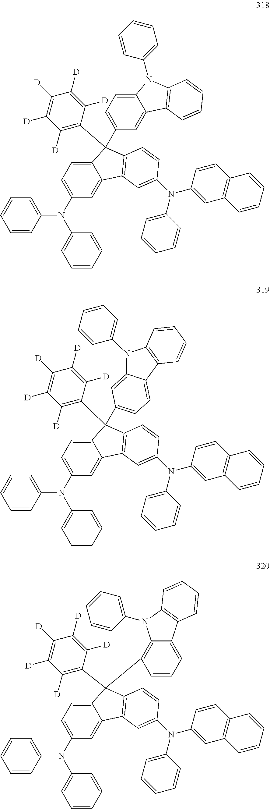


Priority Applications (1)
| Application Number | Priority Date | Filing Date | Title |
|---|---|---|---|
| US18/496,738 US20240090323A1 (en) | 2019-11-21 | 2023-10-27 | Organic electroluminescence device and amine compound for organic electroluminescence device |
Applications Claiming Priority (2)
| Application Number | Priority Date | Filing Date | Title |
|---|---|---|---|
| KR10-2019-0150292 | 2019-11-21 | ||
| KR1020190150292A KR20210062766A (en) | 2019-11-21 | 2019-11-21 | Organic electroluminescence device and amine compound for organic electroluminescence device |
Related Child Applications (1)
| Application Number | Title | Priority Date | Filing Date |
|---|---|---|---|
| US18/496,738 Continuation US20240090323A1 (en) | 2019-11-21 | 2023-10-27 | Organic electroluminescence device and amine compound for organic electroluminescence device |
Publications (2)
| Publication Number | Publication Date |
|---|---|
| US20210159420A1 US20210159420A1 (en) | 2021-05-27 |
| US11856844B2 true US11856844B2 (en) | 2023-12-26 |
Family
ID=75975084
Family Applications (2)
| Application Number | Title | Priority Date | Filing Date |
|---|---|---|---|
| US17/080,732 Active 2042-04-14 US11856844B2 (en) | 2019-11-21 | 2020-10-26 | Organic electroluminescence device and amine compound for organic electroluminescence device |
| US18/496,738 Pending US20240090323A1 (en) | 2019-11-21 | 2023-10-27 | Organic electroluminescence device and amine compound for organic electroluminescence device |
Family Applications After (1)
| Application Number | Title | Priority Date | Filing Date |
|---|---|---|---|
| US18/496,738 Pending US20240090323A1 (en) | 2019-11-21 | 2023-10-27 | Organic electroluminescence device and amine compound for organic electroluminescence device |
Country Status (2)
| Country | Link |
|---|---|
| US (2) | US11856844B2 (en) |
| KR (1) | KR20210062766A (en) |
Families Citing this family (1)
| Publication number | Priority date | Publication date | Assignee | Title |
|---|---|---|---|---|
| CN116790134A (en) * | 2023-06-21 | 2023-09-22 | 复旦大学 | Near infrared small molecule dye and preparation method and application thereof |
Citations (6)
| Publication number | Priority date | Publication date | Assignee | Title |
|---|---|---|---|---|
| US20110147717A1 (en) * | 2009-12-21 | 2011-06-23 | E. I. Du Pont De Nemours And Company | Deuterated compounds for luminescent applications |
| US20160293843A1 (en) * | 2015-03-31 | 2016-10-06 | Samsung Display Co., Ltd. | Material for an organic electroluminescent device and organic electroluminescent device using the same |
| US20180114906A1 (en) * | 2016-10-25 | 2018-04-26 | Samsung Display Co., Ltd. | Amine compound and organic electroluminescence device including the same |
| KR101994448B1 (en) | 2016-12-28 | 2019-06-28 | 주식회사 엘지화학 | Novel hetero-cyclic compound and organic light emitting device comprising the same |
| WO2020073605A1 (en) * | 2018-10-11 | 2020-04-16 | 上海升翕光电科技有限公司 | Organic luminescent compound, preparation method therefor and organic electroluminescent device containing same |
| US20230025656A1 (en) * | 2021-06-11 | 2023-01-26 | Changchun Hyperions Technology Co.,Ltd. | Triarylamine derivative and organic electroluminescent device thereof |
-
2019
- 2019-11-21 KR KR1020190150292A patent/KR20210062766A/en not_active Application Discontinuation
-
2020
- 2020-10-26 US US17/080,732 patent/US11856844B2/en active Active
-
2023
- 2023-10-27 US US18/496,738 patent/US20240090323A1/en active Pending
Patent Citations (7)
| Publication number | Priority date | Publication date | Assignee | Title |
|---|---|---|---|---|
| US20110147717A1 (en) * | 2009-12-21 | 2011-06-23 | E. I. Du Pont De Nemours And Company | Deuterated compounds for luminescent applications |
| US20160293843A1 (en) * | 2015-03-31 | 2016-10-06 | Samsung Display Co., Ltd. | Material for an organic electroluminescent device and organic electroluminescent device using the same |
| KR20160118123A (en) | 2015-03-31 | 2016-10-11 | 삼성디스플레이 주식회사 | Material for organic electroluminescent device and organic electroluminescent device using the same |
| US20180114906A1 (en) * | 2016-10-25 | 2018-04-26 | Samsung Display Co., Ltd. | Amine compound and organic electroluminescence device including the same |
| KR101994448B1 (en) | 2016-12-28 | 2019-06-28 | 주식회사 엘지화학 | Novel hetero-cyclic compound and organic light emitting device comprising the same |
| WO2020073605A1 (en) * | 2018-10-11 | 2020-04-16 | 上海升翕光电科技有限公司 | Organic luminescent compound, preparation method therefor and organic electroluminescent device containing same |
| US20230025656A1 (en) * | 2021-06-11 | 2023-01-26 | Changchun Hyperions Technology Co.,Ltd. | Triarylamine derivative and organic electroluminescent device thereof |
Also Published As
| Publication number | Publication date |
|---|---|
| US20240090323A1 (en) | 2024-03-14 |
| US20210159420A1 (en) | 2021-05-27 |
| KR20210062766A (en) | 2021-06-01 |
Similar Documents
| Publication | Publication Date | Title |
|---|---|---|
| US11793068B2 (en) | Amine compound and organic electroluminescence device including the same | |
| US20220416174A1 (en) | Organic electroluminescence device and polycyclic compound for organic electroluminescence device | |
| US11101442B2 (en) | Organic electroluminescence device and amine compound for organic electroluminescence device | |
| US20210119135A1 (en) | Luminescence device and amine compound for luminescence device | |
| US11581493B2 (en) | Organic electroluminescence device and condensed polycyclic compound for organic electroluminescence device | |
| US11825744B2 (en) | Organic electroluminescence device and condensed cyclic compound for organic electroluminescence device | |
| US11980091B2 (en) | Organic electroluminescence device and compound for organic electroluminescence device | |
| US11871651B2 (en) | Organic electroluminescence device and polycyclic compound for organic electroluminescence device | |
| US20210273174A1 (en) | Organic electroluminescence device and polycyclic compound for organic electroluminescence device | |
| US20210126197A1 (en) | Organic electroluminescence device and amine compound for organic electroluminescence device | |
| US20240090323A1 (en) | Organic electroluminescence device and amine compound for organic electroluminescence device | |
| US12089489B2 (en) | Organic electroluminescence device and diamine compound for organic electroluminescence device | |
| US20230010262A1 (en) | Organic electroluminescence device and amine compound for organic electroluminescence device | |
| US11785837B2 (en) | Organic electroluminescence device and polycyclic compound for organic electroluminescence device | |
| US11849633B2 (en) | Organic electroluminescence device and monoamine compound for organic electroluminescence device | |
| US12069941B2 (en) | Organic electroluminescence device and polycyclic compound for organic electroluminescence device | |
| US11985893B2 (en) | Organic electroluminescence device and aromatic compound for organic electroluminescence device | |
| US20210210696A1 (en) | Organic electroluminescence device and nitrogen-containing compound for organic electroluminescence device | |
| US12052915B2 (en) | Organic electroluminescence device and polycyclic compound for organic electroluminescence device | |
| US20210126199A1 (en) | Organic electroluminescence device and polycyclic compound for same | |
| US20210126195A1 (en) | Organic electroluminescence device and polycyclic compound for organic electroluminescence device | |
| US11737356B2 (en) | Organic electroluminescence device and amine compound for organic electroluminescence device | |
| US12035552B2 (en) | Organic electroluminescence device and amine compound for organic electroluminescence device | |
| US11770973B2 (en) | Organic electroluminescence device and amine compound for organic electroluminescence device | |
| US11980088B2 (en) | Organic electroluminescence device and amine compound for organic electroluminescence device |
Legal Events
| Date | Code | Title | Description |
|---|---|---|---|
| AS | Assignment |
Owner name: SAMSUNG DISPLAY CO., LTD., KOREA, REPUBLIC OF Free format text: ASSIGNMENT OF ASSIGNORS INTEREST;ASSIGNORS:KIM, DONGJUN;KIM, MINJI;JEONG, EUNJAE;AND OTHERS;REEL/FRAME:054170/0455 Effective date: 20201020 |
|
| FEPP | Fee payment procedure |
Free format text: ENTITY STATUS SET TO UNDISCOUNTED (ORIGINAL EVENT CODE: BIG.); ENTITY STATUS OF PATENT OWNER: LARGE ENTITY |
|
| STPP | Information on status: patent application and granting procedure in general |
Free format text: APPLICATION DISPATCHED FROM PREEXAM, NOT YET DOCKETED |
|
| STPP | Information on status: patent application and granting procedure in general |
Free format text: DOCKETED NEW CASE - READY FOR EXAMINATION |
|
| STPP | Information on status: patent application and granting procedure in general |
Free format text: NON FINAL ACTION MAILED |
|
| STPP | Information on status: patent application and granting procedure in general |
Free format text: NOTICE OF ALLOWANCE MAILED -- APPLICATION RECEIVED IN OFFICE OF PUBLICATIONS |
|
| STPP | Information on status: patent application and granting procedure in general |
Free format text: PUBLICATIONS -- ISSUE FEE PAYMENT VERIFIED |
|
| STCF | Information on status: patent grant |
Free format text: PATENTED CASE |