US11846281B2 - Two-way pump selectable valve and bypass waste channel - Google Patents
Two-way pump selectable valve and bypass waste channel Download PDFInfo
- Publication number
- US11846281B2 US11846281B2 US16/949,740 US202016949740A US11846281B2 US 11846281 B2 US11846281 B2 US 11846281B2 US 202016949740 A US202016949740 A US 202016949740A US 11846281 B2 US11846281 B2 US 11846281B2
- Authority
- US
- United States
- Prior art keywords
- port
- chamber
- selectable
- cartridge
- valve
- Prior art date
- Legal status (The legal status is an assumption and is not a legal conclusion. Google has not performed a legal analysis and makes no representation as to the accuracy of the status listed.)
- Active, expires
Links
- 239000002699 waste material Substances 0.000 title claims abstract description 50
- 238000012163 sequencing technique Methods 0.000 claims description 55
- 239000012530 fluid Substances 0.000 claims description 34
- 239000012528 membrane Substances 0.000 claims description 13
- 150000003839 salts Chemical class 0.000 claims description 13
- 239000007853 buffer solution Substances 0.000 claims description 11
- 238000004140 cleaning Methods 0.000 claims description 7
- 238000004891 communication Methods 0.000 claims description 6
- 239000000243 solution Substances 0.000 claims description 6
- 239000000463 material Substances 0.000 abstract description 52
- 238000000018 DNA microarray Methods 0.000 description 83
- 239000002773 nucleotide Substances 0.000 description 32
- 125000003729 nucleotide group Chemical group 0.000 description 32
- 238000000034 method Methods 0.000 description 25
- 239000000203 mixture Substances 0.000 description 24
- 239000003153 chemical reaction reagent Substances 0.000 description 22
- 239000012071 phase Substances 0.000 description 21
- 239000007789 gas Substances 0.000 description 20
- 239000003570 air Substances 0.000 description 19
- DIOQZVSQGTUSAI-UHFFFAOYSA-N decane Chemical compound CCCCCCCCCC DIOQZVSQGTUSAI-UHFFFAOYSA-N 0.000 description 18
- 230000008569 process Effects 0.000 description 18
- 239000000523 sample Substances 0.000 description 18
- 238000010586 diagram Methods 0.000 description 16
- 239000007788 liquid Substances 0.000 description 14
- 238000005259 measurement Methods 0.000 description 14
- 102000039446 nucleic acids Human genes 0.000 description 13
- 108020004707 nucleic acids Proteins 0.000 description 13
- 150000007523 nucleic acids Chemical class 0.000 description 13
- 238000004166 bioassay Methods 0.000 description 12
- 239000011148 porous material Substances 0.000 description 12
- 239000000232 Lipid Bilayer Substances 0.000 description 9
- 150000002632 lipids Chemical class 0.000 description 9
- LFQSCWFLJHTTHZ-UHFFFAOYSA-N Ethanol Chemical compound CCO LFQSCWFLJHTTHZ-UHFFFAOYSA-N 0.000 description 8
- 230000015572 biosynthetic process Effects 0.000 description 8
- WCUXLLCKKVVCTQ-UHFFFAOYSA-M Potassium chloride Chemical compound [Cl-].[K+] WCUXLLCKKVVCTQ-UHFFFAOYSA-M 0.000 description 7
- 239000000872 buffer Substances 0.000 description 7
- 239000000126 substance Substances 0.000 description 7
- 230000006870 function Effects 0.000 description 6
- 239000012472 biological sample Substances 0.000 description 5
- 238000001816 cooling Methods 0.000 description 4
- 239000003792 electrolyte Substances 0.000 description 4
- 239000007787 solid Substances 0.000 description 4
- 239000004094 surface-active agent Substances 0.000 description 4
- 238000001712 DNA sequencing Methods 0.000 description 3
- 238000004458 analytical method Methods 0.000 description 3
- 238000010438 heat treatment Methods 0.000 description 3
- 230000003287 optical effect Effects 0.000 description 3
- 235000011164 potassium chloride Nutrition 0.000 description 3
- 239000001103 potassium chloride Substances 0.000 description 3
- 238000005086 pumping Methods 0.000 description 3
- 239000002250 absorbent Substances 0.000 description 2
- 230000002745 absorbent Effects 0.000 description 2
- 239000012080 ambient air Substances 0.000 description 2
- 238000003556 assay Methods 0.000 description 2
- 238000004590 computer program Methods 0.000 description 2
- 150000002500 ions Chemical class 0.000 description 2
- 229910052751 metal Inorganic materials 0.000 description 2
- 239000002184 metal Substances 0.000 description 2
- SCVFZCLFOSHCOH-UHFFFAOYSA-M potassium acetate Chemical compound [K+].CC([O-])=O SCVFZCLFOSHCOH-UHFFFAOYSA-M 0.000 description 2
- 230000037452 priming Effects 0.000 description 2
- 239000010409 thin film Substances 0.000 description 2
- 102000016928 DNA-directed DNA polymerase Human genes 0.000 description 1
- 108010014303 DNA-directed DNA polymerase Proteins 0.000 description 1
- 102000004190 Enzymes Human genes 0.000 description 1
- 108090000790 Enzymes Proteins 0.000 description 1
- 230000009471 action Effects 0.000 description 1
- 239000012491 analyte Substances 0.000 description 1
- 239000008346 aqueous phase Substances 0.000 description 1
- 230000000712 assembly Effects 0.000 description 1
- 238000000429 assembly Methods 0.000 description 1
- 238000006243 chemical reaction Methods 0.000 description 1
- 239000011248 coating agent Substances 0.000 description 1
- 238000000576 coating method Methods 0.000 description 1
- 239000004020 conductor Substances 0.000 description 1
- 238000013461 design Methods 0.000 description 1
- 238000006073 displacement reaction Methods 0.000 description 1
- 230000005684 electric field Effects 0.000 description 1
- 238000004520 electroporation Methods 0.000 description 1
- 238000007654 immersion Methods 0.000 description 1
- 238000010348 incorporation Methods 0.000 description 1
- 238000009413 insulation Methods 0.000 description 1
- 238000006317 isomerization reaction Methods 0.000 description 1
- 230000007246 mechanism Effects 0.000 description 1
- 238000012986 modification Methods 0.000 description 1
- 230000004048 modification Effects 0.000 description 1
- 238000012856 packing Methods 0.000 description 1
- 229920000642 polymer Polymers 0.000 description 1
- 235000011056 potassium acetate Nutrition 0.000 description 1
- 238000012545 processing Methods 0.000 description 1
- 102000004169 proteins and genes Human genes 0.000 description 1
- 108090000623 proteins and genes Proteins 0.000 description 1
- 239000003507 refrigerant Substances 0.000 description 1
- 239000004065 semiconductor Substances 0.000 description 1
- UYCAUPASBSROMS-AWQJXPNKSA-M sodium;2,2,2-trifluoroacetate Chemical compound [Na+].[O-][13C](=O)[13C](F)(F)F UYCAUPASBSROMS-AWQJXPNKSA-M 0.000 description 1
- 238000003786 synthesis reaction Methods 0.000 description 1
- 239000004557 technical material Substances 0.000 description 1
- 238000005382 thermal cycling Methods 0.000 description 1
Images


Classifications
-
- F—MECHANICAL ENGINEERING; LIGHTING; HEATING; WEAPONS; BLASTING
- F04—POSITIVE - DISPLACEMENT MACHINES FOR LIQUIDS; PUMPS FOR LIQUIDS OR ELASTIC FLUIDS
- F04B—POSITIVE-DISPLACEMENT MACHINES FOR LIQUIDS; PUMPS
- F04B53/00—Component parts, details or accessories not provided for in, or of interest apart from, groups F04B1/00 - F04B23/00 or F04B39/00 - F04B47/00
- F04B53/10—Valves; Arrangement of valves
-
- B—PERFORMING OPERATIONS; TRANSPORTING
- B01—PHYSICAL OR CHEMICAL PROCESSES OR APPARATUS IN GENERAL
- B01L—CHEMICAL OR PHYSICAL LABORATORY APPARATUS FOR GENERAL USE
- B01L3/00—Containers or dishes for laboratory use, e.g. laboratory glassware; Droppers
- B01L3/50—Containers for the purpose of retaining a material to be analysed, e.g. test tubes
- B01L3/502—Containers for the purpose of retaining a material to be analysed, e.g. test tubes with fluid transport, e.g. in multi-compartment structures
- B01L3/5027—Containers for the purpose of retaining a material to be analysed, e.g. test tubes with fluid transport, e.g. in multi-compartment structures by integrated microfluidic structures, i.e. dimensions of channels and chambers are such that surface tension forces are important, e.g. lab-on-a-chip
- B01L3/502715—Containers for the purpose of retaining a material to be analysed, e.g. test tubes with fluid transport, e.g. in multi-compartment structures by integrated microfluidic structures, i.e. dimensions of channels and chambers are such that surface tension forces are important, e.g. lab-on-a-chip characterised by interfacing components, e.g. fluidic, electrical, optical or mechanical interfaces
-
- B—PERFORMING OPERATIONS; TRANSPORTING
- B01—PHYSICAL OR CHEMICAL PROCESSES OR APPARATUS IN GENERAL
- B01L—CHEMICAL OR PHYSICAL LABORATORY APPARATUS FOR GENERAL USE
- B01L3/00—Containers or dishes for laboratory use, e.g. laboratory glassware; Droppers
- B01L3/50—Containers for the purpose of retaining a material to be analysed, e.g. test tubes
- B01L3/502—Containers for the purpose of retaining a material to be analysed, e.g. test tubes with fluid transport, e.g. in multi-compartment structures
- B01L3/5027—Containers for the purpose of retaining a material to be analysed, e.g. test tubes with fluid transport, e.g. in multi-compartment structures by integrated microfluidic structures, i.e. dimensions of channels and chambers are such that surface tension forces are important, e.g. lab-on-a-chip
- B01L3/502738—Containers for the purpose of retaining a material to be analysed, e.g. test tubes with fluid transport, e.g. in multi-compartment structures by integrated microfluidic structures, i.e. dimensions of channels and chambers are such that surface tension forces are important, e.g. lab-on-a-chip characterised by integrated valves
-
- F—MECHANICAL ENGINEERING; LIGHTING; HEATING; WEAPONS; BLASTING
- F16—ENGINEERING ELEMENTS AND UNITS; GENERAL MEASURES FOR PRODUCING AND MAINTAINING EFFECTIVE FUNCTIONING OF MACHINES OR INSTALLATIONS; THERMAL INSULATION IN GENERAL
- F16K—VALVES; TAPS; COCKS; ACTUATING-FLOATS; DEVICES FOR VENTING OR AERATING
- F16K27/00—Construction of housing; Use of materials therefor
- F16K27/003—Housing formed from a plurality of the same valve elements
-
- B—PERFORMING OPERATIONS; TRANSPORTING
- B01—PHYSICAL OR CHEMICAL PROCESSES OR APPARATUS IN GENERAL
- B01L—CHEMICAL OR PHYSICAL LABORATORY APPARATUS FOR GENERAL USE
- B01L2200/00—Solutions for specific problems relating to chemical or physical laboratory apparatus
- B01L2200/02—Adapting objects or devices to another
- B01L2200/026—Fluid interfacing between devices or objects, e.g. connectors, inlet details
- B01L2200/027—Fluid interfacing between devices or objects, e.g. connectors, inlet details for microfluidic devices
-
- B—PERFORMING OPERATIONS; TRANSPORTING
- B01—PHYSICAL OR CHEMICAL PROCESSES OR APPARATUS IN GENERAL
- B01L—CHEMICAL OR PHYSICAL LABORATORY APPARATUS FOR GENERAL USE
- B01L2200/00—Solutions for specific problems relating to chemical or physical laboratory apparatus
- B01L2200/06—Fluid handling related problems
- B01L2200/0647—Handling flowable solids, e.g. microscopic beads, cells, particles
- B01L2200/0663—Stretching or orienting elongated molecules or particles
-
- B—PERFORMING OPERATIONS; TRANSPORTING
- B01—PHYSICAL OR CHEMICAL PROCESSES OR APPARATUS IN GENERAL
- B01L—CHEMICAL OR PHYSICAL LABORATORY APPARATUS FOR GENERAL USE
- B01L2300/00—Additional constructional details
- B01L2300/06—Auxiliary integrated devices, integrated components
- B01L2300/0627—Sensor or part of a sensor is integrated
-
- B—PERFORMING OPERATIONS; TRANSPORTING
- B01—PHYSICAL OR CHEMICAL PROCESSES OR APPARATUS IN GENERAL
- B01L—CHEMICAL OR PHYSICAL LABORATORY APPARATUS FOR GENERAL USE
- B01L2300/00—Additional constructional details
- B01L2300/08—Geometry, shape and general structure
- B01L2300/0861—Configuration of multiple channels and/or chambers in a single devices
- B01L2300/0867—Multiple inlets and one sample wells, e.g. mixing, dilution
-
- B—PERFORMING OPERATIONS; TRANSPORTING
- B01—PHYSICAL OR CHEMICAL PROCESSES OR APPARATUS IN GENERAL
- B01L—CHEMICAL OR PHYSICAL LABORATORY APPARATUS FOR GENERAL USE
- B01L2400/00—Moving or stopping fluids
- B01L2400/06—Valves, specific forms thereof
- B01L2400/0633—Valves, specific forms thereof with moving parts
- B01L2400/0644—Valves, specific forms thereof with moving parts rotary valves
-
- G—PHYSICS
- G01—MEASURING; TESTING
- G01N—INVESTIGATING OR ANALYSING MATERIALS BY DETERMINING THEIR CHEMICAL OR PHYSICAL PROPERTIES
- G01N33/00—Investigating or analysing materials by specific methods not covered by groups G01N1/00 - G01N31/00
- G01N33/48—Biological material, e.g. blood, urine; Haemocytometers
- G01N33/483—Physical analysis of biological material
- G01N33/487—Physical analysis of biological material of liquid biological material
- G01N33/48707—Physical analysis of biological material of liquid biological material by electrical means
- G01N33/48721—Investigating individual macromolecules, e.g. by translocation through nanopores
Definitions
- biotechnologists to begin packing traditionally bulky sensing tools into smaller and smaller form factors, onto so-called biochips.
- Often utilizing a biochip requires liquid, gas, or other substances to be deposited and removed in a controlled sequence on or near the biochip.
- various reagents and biological samples are flowed over the biochip in a controlled sequence to prepare the biochip, perform a measurement using the biochip, and clean the biochip for a next measurement.
- Manually performing this sequence is slow, error prone, and cost ineffective.
- the transitioning from one measurement sample to a next measurement sample has been typically inefficient due to the steps involved in cleaning, resetting, refilling, and replacing various components. It would be desirable to develop items and techniques that are more efficient, robust, and cost-effective.
- FIG. 1 illustrates an embodiment of a cell 100 in a nanopore-based sequencing chip.
- FIG. 2 illustrates an embodiment of a cell 200 performing nucleotide sequencing with the Nano-SBS technique.
- FIG. 3 illustrates an embodiment of a cell about to perform nucleotide sequencing with pre-loaded tags.
- FIG. 4 illustrates an embodiment of a process 400 for nucleic acid sequencing with pre-loaded tags.
- FIG. 5 is a schematic diagram illustrating an embodiment of at least a portion of a biological sensor system.
- FIG. 6 is a schematic diagram illustrating another embodiment of at least a portion of a biological sensor cartridge system.
- FIGS. 7 A- 7 C are schematic diagrams illustrating another embodiment of at least a portion of a biological sensor cartridge system.
- FIG. 8 A is a diagram illustrating an embodiment of a cartridge.
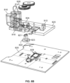
- FIG. 8 B is a diagram illustrating an embodiment of at least a portion of internal components of a cartridge.
- FIG. 8 C is a diagram illustrating an embodiment of a cartridge and an instrument system that engages the cartridge.
- FIG. 9 is a diagram illustrating another embodiment of at least a portion of internal components of a cartridge.
- FIG. 10 is a schematic diagram illustrating an embodiment of a linear valve.
- FIG. 11 is a flowchart illustrating an embodiment of a process for flowing different types of materials (e.g., liquids or gases) through the cells of a nanopore-based sequencing biochip during different phases of the biochip operation.
- materials e.g., liquids or gases
- the invention can be implemented in numerous ways, including as a process; an apparatus; a system; a composition of matter; a computer program product embodied on a computer readable storage medium; and/or a processor, such as a processor configured to execute instructions stored on and/or provided by a memory coupled to the processor.
- these implementations, or any other form that the invention may take, may be referred to as techniques.
- the order of the steps of disclosed processes may be altered within the scope of the invention.
- a component such as a processor or a memory described as being configured to perform a task may be implemented as a general component that is temporarily configured to perform the task at a given time or a specific component that is manufactured to perform the task.
- the term ‘processor’ refers to one or more devices, circuits, and/or processing cores configured to process data, such as computer program instructions.
- Nanopore membrane devices having pore sizes on the order of one nanometer in internal diameter have shown promise in rapid nucleotide sequencing.
- a voltage potential is applied across a nanopore immersed in a conducting fluid, a small ion current attributed to the conduction of ions across the nanopore can be observed.
- the size of the current is sensitive to the pore size.
- a nanopore-based sequencing chip may be used for DNA sequencing.
- a nanopore-based sequencing chip incorporates a large number of sensor cells configured as an array. For example, an array of one million cells may include 1000 rows by 1000 columns of cells.
- FIG. 1 illustrates an embodiment of a cell 100 in a nanopore-based sequencing chip.
- a membrane 102 is formed over the surface of the cell.
- membrane 102 is a lipid bilayer.
- the bulk electrolyte 114 containing protein nanopore transmembrane molecular complexes (PNTMC) and the analyte of interest is placed directly onto the surface of the cell.
- a single PNTMC 104 is inserted into membrane 102 by electroporation.
- the individual membranes in the array are neither chemically nor electrically connected to each other.
- each cell in the array is an independent sequencing machine, producing data unique to the single polymer molecule associated with the PNTMC.
- PNTMC 104 operates on the analytes and modulates the ionic current through the otherwise impermeable bilayer.
- analog measurement circuitry 112 is connected to a metal electrode 110 covered by a thin film of electrolyte 108 .
- the thin film of electrolyte 108 is isolated from the bulk electrolyte 114 by the ion-impermeable membrane 102 .
- PNTMC 104 crosses membrane 102 and provides the only path for ionic current to flow from the bulk liquid to working electrode 110 .
- the cell also includes a counter electrode (CE) 116 , which is an electrochemical potential sensor.
- CE counter electrode
- the cell also includes a reference electrode 117 .
- a nanopore array enables parallel sequencing using the single molecule nanopore-based sequencing by synthesis (Nano-SBS) technique.
- FIG. 2 illustrates an embodiment of a cell 200 performing nucleotide sequencing with the Nano-SBS technique.
- a template 202 to be sequenced and a primer are introduced to cell 200 .
- four differently tagged nucleotides 208 are added to the bulk aqueous phase.
- the tail of the tag is positioned in the barrel of nanopore 206 .
- the tag held in the barrel of nanopore 206 generates a unique ionic blockade signal 210 , thereby electronically identifying the added base due to the tags' distinct chemical structures.
- FIG. 3 illustrates an embodiment of a cell about to perform nucleotide sequencing with pre-loaded tags.
- a nanopore 301 is formed in a membrane 302 .
- An enzyme 303 e.g., a polymerase, such as a DNA polymerase
- polymerase 303 is covalently attached to nanopore 301 .
- Polymerase 303 is associated with a nucleic acid molecule 304 to be sequenced.
- the nucleic acid molecule 304 is circular.
- nucleic acid molecule 304 is linear.
- a nucleic acid primer 305 is hybridized to a portion of nucleic acid molecule 304 .
- Polymerase 303 catalyzes the incorporation of nucleotides 306 onto primer 305 using single stranded nucleic acid molecule 304 as a template.
- Nucleotides 306 comprise tag species (“tags”) 307 .
- FIG. 4 illustrates an embodiment of a process 400 for nucleic acid sequencing with pre-loaded tags.
- a tagged nucleotide (one of four different types: A, T, G, or C) is not associated with the polymerase.
- a tagged nucleotide is associated with the polymerase.
- the polymerase is in close proximity to the nanopore. The tag is pulled into the nanopore by an electrical field generated by a voltage applied across the membrane and/or the nanopore.
- Some of the associated tagged nucleotides are not base paired with the nucleic acid molecule. These non-paired nucleotides typically are rejected by the polymerase within a time scale that is shorter than the time scale for which correctly paired nucleotides remain associated with the polymerase. Since the non-paired nucleotides are only transiently associated with the polymerase, process 400 as shown in FIG. 4 typically does not proceed beyond stage B.
- the conductance of the nanopore is ⁇ 300 pico Siemens (300 pS).
- the conductance of the nanopore is about 60 pS, 80 pS, 100 pS, or 120 pS corresponding to one of the four types of tagged nucleotides.
- the polymerase undergoes an isomerization and a transphosphorylation reaction to incorporate the nucleotide into the growing nucleic acid molecule and release the tag molecule.
- a unique conductance signal e.g., see signal 210 in FIG. 2
- the released tag passes through the nanopore.
- tagged nucleotides that are not incorporated into the growing nucleic acid molecule will also pass through the nanopore, as seen in stage F of FIG. 4 .
- the unincorporated nucleotide can be detected by the nanopore in some instances, but the method provides a means for distinguishing between an incorporated nucleotide and an unincorporated nucleotide based at least in part on the time for which the nucleotide is detected in the nanopore.
- Tags bound to unincorporated nucleotides pass through the nanopore quickly and are detected for a short period of time (e.g., less than 10 ms), while tags bound to incorporated nucleotides are loaded into the nanopore and detected for a long period of time (e.g., at least 10 ms).
- a fluid/gas delivery system for a sensor chip is disclosed.
- a biological assay (e.g., nucleotide/nucleic acid sequencing) chip requires fluids and/or gases to be provided on the sensor chip, and a delivery system provides at least a portion of the materials required to perform the assay.
- a plurality of selectable ports are arranged on a first assembly. Each selectable port is in communication with a separate channel.
- each of the separate channels are connected to a different reagent, liquid, gas, waste container, etc. where material could be delivered/pushed or drawn/pulled.
- One of the separate channels may be connected to a biochip and material could be delivered/pushed or drawn/pulled to/from the biochip using this separate channel.
- a second assembly is movable in relation to the first assembly and the second assembly has a channel that is mechanically connectable to different ones of the plurality of ports on the first assembly by motion of the second assembly relative to the first assembly.
- a mechanical interface is configured to engage an actuator so that relative motion of the first assembly and the second assembly is affected by the actuator.
- the second assembly includes a selection port that can be moved by an actuator/motor to be connected to any one of the plurality of selectable ports that are arranged on the first assembly.
- the selection port may be connected to only one port of the plurality of selectable ports of the first assembly at one time and the other selectable ports of the first assembly that are not connected to the selection port are sealed closed (e.g., sealed by the second assembly).
- the selection port of the second assembly is connected to a pump and a chamber/channel that are utilized to deliver/push and/or draw/pull materials to/from the selected port of the plurality of selectable ports of the first assembly.
- any of the plurality of selectable ports can be selected to be connected to a two-way pump port.
- a pump is configured to either draw or deliver fluid/gas from/to the two-way pump port.
- a chamber is connected to a first chamber port that is included in the plurality of selectable ports.
- the first chamber port can be selected to connect to the two-way pump port.
- the chamber is also connected to a second chamber port.
- the chamber includes a biochip and the first chamber port at least allows a reagent to enter the chamber and the second chamber port at least allows the reagent to exit the chamber after passing through the biochip in the chamber.
- a waste port is included in the plurality of ports.
- a selection may be made to flow material to be discarded either through the second chamber port or to the waste port without passing through the second chamber port.
- a selection may be made to flow material to be discarded either through the second chamber port or to the waste port without passing through the second chamber port.
- materials that ideally should not flow entirely through the chamber/biochip in an assay process may be discarded via the selectable waste port rather than a chamber port.
- FIG. 5 is a schematic diagram illustrating an embodiment of at least a portion of a biological sensor system.
- the biological sensor system is a nanopore-based nucleotide sequencing system.
- the sensor system includes cartridge 502 .
- Cartridge 502 engages with an instrument system, interfaces with the instrument system, and functions together with the instrument system to perform a biological assay (e.g., nanopore-based nucleotide sequencing).
- a biological assay e.g., nanopore-based nucleotide sequencing
- one or more of the components shown to be not included in cartridge 502 may be included on the instrument system.
- Cartridge 502 is removable from the instrument system and another cartridge may be engaged with the instrument system. By utilizing a removable cartridge, the components of the cartridge may be replaced quickly and easily on the instrument system without the need to clean and reuse the components of the cartridge. For example, the cartridge may be replaced for each different biological sample to be assayed by the instrument system.
- Cartridge 502 includes biochip 504 , radial valve 506 , container 508 , container 510 and container 512 .
- Each of containers 508 , 510 and 512 may hold a liquid, a reagent, a gas, a solid (e.g., suspended in liquid) and any other substance to be utilized in performing a biological measurement.
- container 508 holds a lipid and decane mix
- container 510 holds a sample and pore/polymerase mix
- container 512 holds a StartMix.
- Container 510 and container 512 are sensitive to temperature changes and thermal block 514 is thermally coupled to containers 510 and 512 .
- thermal block 514 provides thermal cooling to contents of container 510 and container 512 .
- thermal block 514 provides thermal heating and/or cooling to raise, lower, and/or maintain a temperature of contents of container 510 and container 512 .
- thermal block 514 is not a part of cartridge 502 and is a part of the instrument system.
- Biochip 504 may be the nanopore-based sequencing chip described elsewhere in the specification. Biochip 504 is electrically connected/interfaced with the instrument system and electrical measurement data is read from biochip 504 and exported out of the biochip 504 to the instrument system for storage/analysis.
- cartridge 502 includes a circuit board that provides electrical contact interfaces between biochip 504 and the instrument system. Biochip 504 is thermally coupled to the instrument system via a thermoelectric cooler (TEC)/heat sink assembly 516 .
- TEC thermoelectric cooler
- the TEC/Heat sink assembly 516 allows the temperature of the biochip 504 to be controlled.
- the biochip and its fluid contents can be held at a constant temperature (e.g., warm or cold) and/or exposed to varying temperatures in a controlled manner (e.g., thermal cycling).
- Radial valve 506 mechanically engages actuator/motor 518 of the instrument system.
- Actuator/motor 518 is separate from cartridge 502 .
- Motor 518 actuates a movable assembly of radial valve 506 to select a desired port of radial valve 506 .
- motor 518 engages a movable assembly of radial valve 506 directly or indirectly via one or more gears, worm screws, or friction engagements (e.g., friction wheel).
- Radial valve 506 includes central port 520 and selectable ports 521 - 526 that are arranged coaxially in a rotary configuration. Radial valve 506 may be rotated via actuator/motor 518 to select one of selectable ports 521 - 526 as the active/open port. The other not selected ports of selectable ports 521 - 526 may or may not be automatically sealed/closed when the selected port is selected. Materials may be passed between central port 520 and the selected port. For example, a fluid/gas passage channel is created between central port 520 and the selected port. Central port 520 is connected to interface 528 via a channel (e.g., tube). Interface port 528 is an interface of cartridge 502 where materials may enter/exit cartridge 502 .
- a channel e.g., tube
- interfaces of the cartridge include a needle septum, a flap valve or a ball displacement valve.
- Central port 520 is connected to pump 530 via interface 528 .
- Pump 530 includes a syringe pump that may draw or push content into or out of pump chamber 532 .
- Pump 530 includes a secondary radial value 534 .
- chamber 532 is a fluidic channel such as tubing.
- Pump 530 is a two-way pump that can deliver/push and draw/pull materials in to/out of pump chamber 532 .
- Radial valve 534 may be configured to connect pump chamber 532 to any of selectable ports A-F as shown in FIG. 5 . Radial valve 534 may be rotated via an actuator/motor to select one of selectable ports A-F as the selected active/open port. The other not selected ports of selectable ports A-F are automatically sealed/closed when the selected port is selected. Liquid/gas may be passed between pump chamber 532 and the selected port of valve 534 . Port A is connected to a salt buffer solution. Port B is connected to a surfactant solution. Port C is connected to ethanol. Port D is connected to central port 520 via interface 528 .
- pump 530 when port D is selected on radial valve 534 , pump 530 is able to deliver/push any material in pump chamber 532 to a selected port of radial valve 506 and pump 530 is able to pull any material from the selected port of radial valve 506 into chamber 532 .
- Port E is connected to a waste container where content in chamber 532 can be discarded.
- Port F is connected to an air vent.
- ambient air can be drawn into chamber 532 when port F is selected on radial valve 534 .
- valve 506 may include additional ports for additional reagents and central port 520 is connected to pump chamber 532 without another intervening radial valve.
- a biological assay is performed using biochip 504 .
- a reagent to be pushed into chip 504 may be placed in chamber 532 by selecting one of selectable ports A-C on valve 534 connected to a desired reagent, pumping content of the selected port into chamber 532 , then selecting port D on valve 534 and selecting port 521 on valve 506 , and pushing the content of chamber 532 to chip 504 .
- a reagent to be pushed into chip 504 may be placed in chamber 532 by selecting port D on valve 534 and selecting one of selectable ports 522 - 524 on valve 506 connected to the desired reagent, pumping content of the selected port into pump chamber 532 , then selecting port 521 on valve 506 and pushing the content of chamber 532 to chip 504 .
- a reagent to be pushed into chip 504 may be drawn out of chambers 508 , 510 or 512 by selecting the corresponding port 524 , 523 or 522 , and selecting port D on valve 534 .
- a reagent is drawn into fluid channel 527 , but not past fluid interface 528 which keeps the reagent within the cartridge and does not contaminate surfaces outside of the cartridge (e.g. pump chamber 532 ).
- Port 521 can then be selected on valve 506 , and the reagent can be pushed into the chip 504 .
- Interface 536 is an interface of cartridge 502 where waste materials to be discarded may exit cartridge 502 . Material in the chamber of chip 504 may be pushed out of the chamber and into waste container 538 via chamber exit port 535 and interface 536 .
- port 521 is selected on valve 506 and pump 530 pulls material out of the chamber of chip 504 .
- port 526 is selected and the material to be discarded in pump chamber 532 is pushed out into waste container 538 via an alternative channel path that does not enter the chamber of chip 504 and does not include chamber port 535 yet still exits via interface port 536 .
- Other materials pumped from other sources by pump 530 to be discarded may also be pushed into waste container 538 bypassing chip 504 via the alternative channel path.
- waste container 538 examples include a vented container, an expandable container, a one-way valve container, and an absorbent material filled container (e.g., to prevent flow back onto chip 504 ). In an alternative embodiment, waste container 538 is included in cartridge 502 .
- FIG. 5 is merely an example and has been simplified to illustrate the embodiment clearly.
- the radial valves shown in FIG. 5 may include any number of selectable ports. Additional components not shown in FIG. 5 may also exist.
- FIG. 6 is a schematic diagram illustrating another embodiment of at least a portion of a biological sensor cartridge system.
- the biological sensor cartridge system is a nanopore-based nucleotide sequencing system.
- the sensor system includes cartridge 602 .
- Cartridge 602 engages with an instrument system, interfaces with the instrument system, and functions together with the instrument system to perform a biological assay (e.g., nanopore-based nucleotide sequencing).
- a biological assay e.g., nanopore-based nucleotide sequencing
- one or more of the components shown to be not included in cartridge 602 may be included on the instrument system.
- Cartridge 602 is removable from the instrument system and another cartridge may be engaged with the instrument system. By utilizing a removable cartridge, the components of the cartridge may be replaced quickly and easily on the instrument system without the need to clean and reuse the components of the cartridge. For example, the cartridge may be replaced for each different biological sample to be assayed by the instrument system.
- Cartridge 602 includes biochip 604 in a chamber, radial valve 606 , and containers 608 , 610 , 612 , 640 , 642 , and 644 .
- Each of containers 608 , 610 , 612 , 640 , 642 and 644 may hold a liquid, a reagent, a gas, a solid (e.g., suspended in liquid), and any other substance to be utilized in performing a biological measurement.
- container 608 holds a lipid and decane mix
- container 610 holds a sample and pore/polymerase mix
- container 612 holds a StartMix
- container 640 holds ethanol
- container 642 holds a surfactant solution
- container 644 holds a salt buffer solution.
- container 610 and container 612 are sensitive to temperature changes and a thermal block provides thermal heating and/or cooling to raise, lower, and/or maintain a temperature of contents of container 610 and container 612 .
- Biochip 604 may be the nanopore-based sequencing chip described elsewhere in the specification. Biochip 604 is electrically connected/interfaced with the instrument system and electrical measurement data is read from biochip 604 and exported out of the biochip 604 to the instrument system for storage/analysis.
- cartridge 602 includes a circuit board that provides an electrical contact interface between biochip 604 and the instrument system. Biochip 604 is thermally coupled to the instrument system via TEC/heat sink assembly 616 . TEC/heat sink assembly 616 allows thermal energy of biochip 604 to be dissipated via assembly 616 .
- Radial valve 606 mechanically engages actuator/motor 618 of the instrument system.
- Actuator/motor 618 is separate from cartridge 602 .
- Motor 618 actuates a movable assembly of radial valve 606 to select a desired port of radial valve 606 .
- motor 618 engages a movable assembly of radial valve 606 directly or indirectly via one or more gears, worm screws, or friction engagements (e.g., friction wheel).
- Radial valve 606 includes central port 620 and selectable ports 621 - 628 that are arranged coaxially in a rotary configuration. Radial valve 606 may be rotated via actuator/motor 618 to select one of selectable ports 621 - 628 as the active/open port. The other not selected ports of selectable ports 621 - 628 are automatically sealed/closed when the selected port is selected. Selectable port 628 is connected to an air vent. For example, ambient air can be drawn into chamber 632 when port 628 is selected on radial valve 606 . Materials may be passed between central port 620 and the selected port. For example, a fluid/gas passage channel is created between central port 620 and the selected port. Central port 620 is connected to pump chamber 632 .
- the pump chamber is located external to cartridge 602 and central port 620 is connected to the external pump chamber via an interface port of cartridge 602 connected to central port 620 via a channel (e.g., tube).
- Pump chamber 632 is a part of a two-way syringe pump that may draw or push content into or out of pump chamber 632 .
- pump chamber 632 is a fluidic channel such as tubing.
- a piston of pump chamber 632 mechanically engages a moveable assembly of actuator/motor 630 of the instrument system directly or indirectly via one or more gears, worm screws, or friction engagements.
- the push/pull action of the syringe pump is controlled by actuating actuator/motor 630 .
- Materials may be passed between pump chamber 632 and the selected port of valve 606 . For example, material may be pushed into chamber 632 from a selected port of valve 606 and material in chamber 632 may be pushed out of chamber 632 to a selected port of valve 606 .
- a biological assay is performed using biochip 604 .
- a reagent to be delivered/pushed into chip 604 may be placed in chamber 632 by selecting one of selectable ports 622 - 628 on valve 606 connected to a desired reagent/gas, pumping content of the selected port into pump chamber 632 , then selecting port selecting port 621 on valve 606 and pushing the content of pump chamber 632 to chip 604 .
- a material flowed on chip 604 needs to be discarded as a next material is flowed across chip 604 to exit the chamber of 604 .
- Material in the chamber of chip 604 may be pushed out of the chamber via chamber port 651 and into waste container 638 .
- port 621 is selected on valve 606 and material on the chip is pumped into pump chamber 632 , then pushed out into waste container 638 via bypass channel path 654 that does not enter the chamber of chip 604 .
- Three-way valve 650 may be switched to either connect port 621 with only the chamber of chip 604 or with only bypass channel 654 , as appropriate.
- the chamber of chip 604 is always connected to port 621 (e.g., without three-way valve 650 ) and a bypass selectable port on radial valve 606 (e.g., alternative embodiment shown as selectable port 660 ) is always connected to bypass channel 654 to allow a connection between pump chamber 632 and waste container 638 without passing through the chamber of chip 604 when the bypass selectable port is selected.
- waste container 638 examples include a vented container, an expandable container, a one-way valve container, and an absorbent material filled container.
- Two-way valve 652 may be configured to switch between allowing or not allowing flow between its connected channels. By opening valve 652 , material in the chamber of chip 604 may be directly pushed out into waste container 638 . By closing valve 652 , backflow on to chip 604 may be prevented when pushing waste into container 638 via bypass channel 654 or when waste content leaks out of waste container 638 . The ability to close valve 652 may also enable the pump to pressurize the fluid or gas on chip 604 . In some embodiments, valve 652 is optional. In an alternative embodiment, valve 652 is a one-way valve.
- linear valve 700 is included in cartridge 502 of FIG. 5 . In some embodiments, linear valve 700 is included in cartridge 602 or FIG. 6 .
- FIGS. 7 A- 7 C are schematic diagrams illustrating another embodiment of at least a portion of a biological sensor cartridge system.
- the biological sensor cartridge system is a nanopore-based nucleotide sequencing system.
- the sensor system includes cartridge 702 .
- Cartridge 702 engages with an instrument system, interfaces with the instrument system, and functions together with the instrument system to perform a biological assay (e.g., nanopore-based nucleotide sequencing).
- the bottom side of cartridge 702 may expose electrical contacts that allow electrical connection between one or more electrical components of cartridge 702 and the instrument system to be engaged with cartridge 702 .
- the electrical contacts of the cartridge electrically interfaces with the instrument system via electrical connector 755 .
- Cartridge 702 is removable from the instrument system and another cartridge may be engaged with the instrument system. By utilizing a removable cartridge, the components of the cartridge may be replaced quickly and easily on the instrument system without the need to clean and reuse the components of the cartridge. For example, the cartridge may be replaced for each different biological sample to be assayed by the instrument system.
- Cartridge 702 includes biochip 704 , radial valve 706 , and containers 708 , 710 , 712 and 740 that are vented.
- containers 708 , 710 , 712 and 740 may hold a liquid, a reagent, a gas, a solid (e.g., suspended in liquid), and any other substance to be utilized in performing a biological measurement.
- container 708 holds a lipid and decane mix
- container 710 holds a sample and pore/polymerase mix
- container 712 holds a StartMix
- container 740 is a reserved spare container.
- At least container 710 and container 712 are sensitive to temperature changes and TEC/heat sink assembly 742 provides thermal heating and/or cooling to raise, lower, and/or maintain a temperature of contents of container 710 and container 712 .
- Containers 708 , 710 , 712 and 740 are each connected to a different selectable port of radial valve 706 .
- the channel paths connecting each container to a corresponding selectable port includes a pipette input that can be utilized to deliver material to the corresponding container and/or selectable port.
- Biochip 704 may be the nanopore-based sequencing chip described elsewhere in the specification. Biochip 704 is electrically connected/interfaced with the instrument system via electrical connector 755 and electrical measurement data is read from biochip 704 and exported out of the biochip 704 to the instrument system for storage/analysis. Biochip 704 is thermally coupled to the instrument system via TEC/heat sink assembly 716 . TEC/heat sink 716 allows thermal energy of biochip 704 to be dissipated via assembly 716 .
- Radial valve 706 mechanically engages actuator/motor 718 of the instrument system.
- Actuator/motor 718 is separate from cartridge 702 .
- Motor 718 actuates a movable assembly of radial valve 706 to select one or more desired port of radial valve 706 .
- motor 718 engages a movable assembly of radial valve 706 directly or indirectly via one or more gears, worm screws, or friction engagements (e.g., friction wheel).
- Radial valve 706 includes central port 720 and can be placed in any one of shown selectable positions 1 - 8 that are arranged coaxially in a rotary configuration. Radial valve 706 is rotated via actuator/motor 718 to select one of selectable positions 1 - 8 . Positions 3 - 6 each correspond to a different selectable port that can be selected as the connected active/open port. The other not selected ports are automatically sealed/closed when the selected port is selected. Using positions 1 and 2 on radial valve 706 , a direct connection between outlet port 735 of the chamber of chip 704 and port 736 connected to a waste container is controlled in addition to controlling a separate direct connection between central port 720 and the inlet port of the chamber of chip 704 .
- a more efficient cartridge design may be achieved due to the multiple functions being performed by the selectable valve.
- a single selectable valve such as valve 706 may be utilized to perform the functions of both radial valve 606 and valve 652 of FIG. 6 .
- the exact position of radial valve 706 is determined using optical encoder 760 .
- optical encoder 760 converts the detected pattern corresponding to a specific position of the moveable assembly to an electrical signal/code that can be utilized to determine the specific position.
- a known “home” position of the radial valve is identified and an open loop control is utilized to rotate the radial valve a controlled amount (e.g., specified number of degrees).
- Channel 722 of radial valve 706 connects central port 720 to the selectable port (e.g., channel 722 has multiple selection ports as shown by circles on channel 722 ).
- channel 722 When a moveable assembly of valve 706 is rotated, channel 722 is physically rotated together. In addition to channel 722 , channel 724 is also moved when the moveable assembly of valve 706 is rotated. However, channel 724 is not directly connected to central port 720 .
- FIG. 7 A shows radial valve 706 in position “1.”
- central port 720 is connected to a selectable port that is connected to the inlet port (e.g., two-way port) of the chamber of chip 704 , allowing materials to be passed between central port 720 and the chamber of chip 704 .
- channel 724 does not connect any ports in position “1.”
- chamber outlet port 735 of the chamber of chip 704 is sealed and not connected to port 736 of the waste container. This may allow chip 704 and contents of the chamber to be pressurized.
- FIG. 7 B shows radial valve 706 in position “2.” In this position, channel 722 still connects central port 720 with the selectable port that is connected to the inlet port of the chamber of chip 704 , allowing materials to be passed between central port 720 and the chamber of chip 704 . However, channel 724 now connects chamber outlet port 735 of the chamber of chip 704 with port 736 of the waste container, allowing waste to flow from the chip chamber to the waste container.
- FIG. 7 C shows radial valve 706 in position “3.” In this position, channel 722 connects central port 720 with the selectable port that is connected to an air vent. Channel 724 does not connect any ports in position “3.”
- Central port 720 is connected to interface 728 via a channel (e.g., tube).
- Interface port 728 is an interface of cartridge 702 where materials may enter/exit cartridge 702 .
- a needle septum is utilized as the interface port.
- Central port 720 is connected to pump 730 via interface 728 .
- Pump 730 includes a syringe pump that may draw or push content into or out of pump chamber 732 .
- Pump 730 includes a secondary radial value.
- chamber 732 is a fluidic channel such as tubing.
- Pump 730 is a two-way pump that can deliver/push and draw/pull materials in to/out of pump chamber 732 .
- pump 730 functions in a similar manner as pump 530 of FIG. 5 .
- Position “8” of radial valve 706 corresponds to a selection of a bypass waste selectable port that allows a connection between central port 720 and a waste container without passing through the chamber of chip 704 when the bypass waste selectable port is
- FIG. 8 A is a diagram illustrating an embodiment of a cartridge.
- cartridge 802 is cartridge 502 of FIG. 5 .
- cartridge 802 shows at least a portion of features of cartridge 602 of FIG. 6 and/or cartridge 702 of FIG. 7 .
- electrical contacts 804 allow electrical connection between one or more electrical components of cartridge 802 and an instrument system to be engaged with cartridge 802 .
- electrical data e.g., electrical measurement/reading data
- electrical contacts 804 are contacts of a circuit board included in cartridge 802 and the circuit board is electrically connected to a biochip.
- Thermal chip interface 806 provides a thermal interface where a heat sink (e.g., heat sink 516 of FIG. 5 or heat sink 616 of FIG. 6 ) can be thermally coupled to a biochip included in cartridge 802 .
- a heat sink e.g., heat sink 516 of FIG. 5 or heat sink 616 of FIG. 6
- the heat sink allows thermal energy of the biochip to be dissipated via the heat sink.
- the heat sink may be a part of the instrument system that receives cartridge 802 .
- Cartridge 802 includes interface port 808 and interface port 810 .
- interface port 808 is interface port 528 of FIG. 5 .
- interface port 808 is connected to a central port of a radial valve (e.g., connected port 520 of FIG. 5 or port 620 of FIG.
- interface port 810 is interface port 536 of FIG. 5 .
- interface port 810 is a waste port.
- Drive engagement port 812 is configured to engage with an actuator/motor to operate a selectable valve. For example, a selection of a selected valve among a plurality of selectable valves is performed by mechanically actuating an engagement mechanism (e.g., gear) exposed in motor drive engagement port 812 .
- motor drive engagement port 812 is utilized to select a selectable port of a radial valve (e.g., radial valve 506 of FIG. 5 or valve 606 of FIG. 6 ).
- motor drive engagement port 812 is utilized to select a selectable port of a linear valve (e.g., linear valve 700 of FIG. 7 ).
- Cartridge 802 includes thermally controlled containers 814 and 816 .
- Container 818 is not to be thermally controlled.
- Containers 814 , 816 , and 818 may hold a liquid, a reagent, a gas, a solid (e.g., suspended in liquid), and any other substance to be utilized in performing a biological measurement.
- container 814 holds a StartMix
- container 816 holds a sample and pore/polymerase mix
- container 818 holds a lipid and decane mix.
- Contents of containers 814 , 816 , and 818 are connected to selectable ports of a selectable valve via separate channels and the contents of the containers may be drawn for use during a biological assay via the corresponding selectable valve.
- Containers 814 and 816 may be thermal-controlled using a thermal block (e.g., thermally controlled using refrigerant, ice, Freon, thermal-electric, etc.) that surrounds at least a portion of containers 814 and 816 to reduce and/or maintain a temperature of its contents (e.g., via thermal conduction through walls of containers 814 and 816 ).
- a thermal block e.g., thermally controlled using refrigerant, ice, Freon, thermal-electric, etc.
- a thermal conductive material probe (e.g., metal rod) is placed within container 814 and/or container 816 and the probe is thermal-controlled (e.g., immersion cooled/heated via an external cool/heat source thermally coupled to the probe (e.g., probe extends through cap of the container such that the probe is partly immersed in contents of the container and partly exposed outside the container where the external thermal source may be coupled)).
- thermal-controlled e.g., immersion cooled/heated via an external cool/heat source thermally coupled to the probe (e.g., probe extends through cap of the container such that the probe is partly immersed in contents of the container and partly exposed outside the container where the external thermal source may be coupled
- FIG. 8 B is a diagram illustrating an embodiment of at least a portion of internal components of a cartridge. In some embodiments, one or more components shown in FIG. 8 B are included cartridge 502 of FIG. 5 , cartridge 702 of FIG. 7 and/or cartridge 602 of FIG. 6 .
- the cartridge includes circuit board 820 .
- Circuit board 820 is electrically coupled to biochip 828 .
- biochip 828 is biochip 504 of FIG. 5 and/or biochip 604 of FIG. 6 .
- the bottom side of circuit board 820 includes electrical contacts 804 shown in FIG. 8 A .
- the cartridge of FIG. 8 B includes a radial valve.
- the radial valve comprises a port selector assembly 822 .
- Selectable ports 824 are arranged coaxially in a rotary configuration on body assembly 825 that remains stationary while selector assembly 822 is rotated to select one of selectable ports 824 as the selected connected port.
- port selector assembly 822 may be rotated using an external actuator/motor to select one of selectable ports 824 as a selected port that will be connected via a channel on selector assembly 822 to central port 821 .
- Central port 821 is connected to interface port 808 where a two-way pump may be coupled.
- selector assembly 822 By rotating selector assembly 822 to a specific location on assembly 825 where connector port 823 becomes aligned with a desired one of selectable ports 824 , a channel between the selected port and central port 821 is established while the other not selected ports of selectable ports 824 become sealed by selector assembly 822 .
- selector assembly 822 includes a mechanical interface (e.g., gear) that is included in or mechanically coupled to gears 826 .
- Selector component 822 is rotated using gears 826 that are mechanically engaged with an actuator via engagement port 812 shown in FIG. 8 A .
- FIG. 8 C is a diagram illustrating an embodiment of a cartridge and an instrument system that engages the cartridge.
- cartridge 802 is cartridge 502 of FIG. 5 .
- cartridge 802 shows at least a portion of features of cartridge 602 of FIG. 6 and/or cartridge 702 of FIG. 7 .
- Cartridge 802 may be pushed down and received by instrument 830 to engage cartridge 802 with instrument 830 .
- Cartridge 802 may be removed from instrument 830 after use and another cartridge may be engaged with instrument 830 for a different sample.
- instrument 830 is at least a portion of a system utilized to perform a biological assay (e.g., nucleotide sequencing).
- Instrument 830 includes male connectors 832 that can be coupled with electrical contacts 804 shown in FIG. 8 A . Electrical connections between a biochip included in cartridge 802 and one or more electrical components of instrument 830 are established via male connectors 832 .
- Instrument 830 includes heat sink 834 . Heat sink 834 can be thermally coupled to a biochip via thermal interface 806 of FIG. 8 A .
- heat sink 834 examples include heat sink 516 of FIG. 5 and heat sink 616 of FIG. 6 .
- Thermal block 836 e.g., cold block of instrument 830 is configured to surround at least a portion of containers 814 and 816 and provide a thermal source to thermally control (e.g., cool/heat) the contents of containers 814 and 816 .
- Thermal block 836 is surrounded by thermal insulation 838 to maintain thermal energy of thermal block 836 .
- cartridge 802 and instrument 830 are mechanically clamped together using one or more clamps.
- FIG. 9 is a diagram illustrating another embodiment of at least a portion of internal components of a cartridge.
- the cartridge components shown in FIG. 9 are included in cartridge 702 of FIG. 7 .
- one or more of the cartridge components shown in FIG. 9 are included in cartridges 502 and/or 602 of FIGS. 5 and 6 .
- the cartridge includes circuit board 920 .
- Circuit board 920 is electrically coupled to biochip 928 .
- biochip 928 is biochip 504 of FIG. 5 , biochip 604 of FIG. 6 and/or biochip 704 of FIG. 7 .
- the cartridge of FIG. 9 includes a radial valve.
- the radial valve comprises port selector assembly 922 . Selectable ports are engaged on both sides of port selector assembly 922 .
- Port selector assembly 922 selector seals and connects ports on both the top (e.g., going to the reagents via upper seal plate assembly 924 ) and bottom (e.g., going to the chip via lower seal plate assembly 926 ) of assembly 922 .
- Port selector assembly 922 is positioned on top of chip 928 and is oriented such that an inlet of the chamber of the chip is positioned along an inner ring of ports on lower seal plate assembly 926 and the outlet of the chamber of the chip is positioned along an outer ring of ports on lower seal plate assembly 926 .
- selector assembly 922 By rotating selector assembly 922 to specific locations on assemblies 924 and 926 where connector ports on selector assembly 922 becomes aligned with desired connector port(s) on upper seal plate assembly 924 and lower seal plate assembly 926 , one or more desired channel connections are created while other connector ports may be sealed. For example, in one position, both inlet and outlet ports of the chamber of the chip are open, allowing fluid flow through the chip.
- port selector assembly 922 includes channels 722 and 724 of FIG. 7 .
- Manifold plate assembly 928 includes containers/reservoirs, a waste container and/or channels.
- Selector assembly 922 includes a mechanical interface (e.g., gear) that is included in or mechanically coupled to drive gears of an actuator/motor.
- Upper seal plate assembly 924 and lower seal plate assembly 926 remain stationary while selector assembly 922 is rotated to a desired position.
- FIG. 10 is a schematic diagram illustrating an embodiment of a linear valve.
- linear valve 1000 may be utilized in its place.
- Selector assembly 1002 moves along track 1012 to select one of selectable ports 1006 - 1011 to be connected to central port 1004 .
- a motor moves selector 1002 along track 1012 to one of a plurality of specific locations on a stationary assembly that each correspond to one of selectable ports 1006 - 1011 .
- an opening connected to the specific selectable port is able to be connected to central port 1004 when selector 1002 is moved to the specific location corresponding to the specific selectable port.
- selector 1002 is at a location of track 1012 corresponding to selectable port 1008 .
- selector assembly 1002 may be moved to the position outlined as 1020 to select port 1010 .
- the motor may be a part of an instrument while linear valve 1000 is a part of a separate removable cartridge that engages with the instrument.
- Selector assembly 1002 may be moved by the motor directly or indirectly via one or more gears, worm screws, pistons, friction engagements, or belts.
- selectable ports 1006 - 1011 When one of selectable ports 1006 - 1011 is selected by selector 1002 as the active/open port (e.g., selector 1002 is moved to a location on track 1012 corresponding to the selected port), other not selected ports of selectable ports 1006 - 1011 are automatically sealed/closed when the selected port is selected.
- Materials may be passed between central port 1004 and the selected port. For example, a fluid/gas passage channel is created between central port 1004 and the selected port.
- Central port 1004 may be connected to a syringe pump (e.g., connected to pump 530 of FIG. 5 , pump 730 of FIG. 7 or to pump of chamber 632 of FIG. 6 ).
- Each of selectable ports 1006 - 1011 may be connected to different reagents, gasses, vents, waste containers, cleaning solutions, biological samples, channels, etc. via separate corresponding channels.
- materials/components utilized in performing a biological assay are connected to the selectable ports.
- the number of ports and/or the shape of the linear valve shown in FIG. 10 is merely an example. Any number of ports and selectable valve shapes may exist in various embodiments.
- FIG. 11 is a flowchart illustrating an embodiment of a process for flowing different types of materials (e.g., liquids or gases) through the cells of a nanopore-based sequencing biochip during different phases of the biochip operation.
- the nanopore-based sequencing biochip operates in different phases, including an initialization and calibration phase (phase 1102 ), a membrane formation phase (phase 1104 ), a nanopore formation phase (phase 1106 ), a sequencing phase (phase 1108 ), and a cleaning and reset phase (phase 1110 ).
- the biochip of FIG. 11 includes cell 100 of FIG. 1 .
- the biochip of FIG. 11 is biochip 504 of FIG. 5 .
- the biochip of FIG. 11 is biochip 604 of FIG. 6 .
- the biochip of FIG. 11 is biochip 704 of FIG. 7 .
- a salt buffer solution is flowed through the cells of the nanopore-based sequencing chip at 1112 .
- the salt buffer solution may be potassium chloride (KCl), potassium acetate (KAc), sodium trifluoroacetate (NaTFA), and the like.
- performing step 1112 using cartridge 602 of FIG. 6 includes using actuator/motor 618 to rotate radial valve 606 to select port 627 , drawing KCl into syringe pump chamber 632 using motor 630 , using motor 618 to rotate radial valve 606 to select port 621 , and pushing out the KCl in pump chamber 632 to the chamber of biochip 604 via selected port 621 .
- a cartridge e.g., cartridge 502 or FIG. 5 or cartridge 602 of FIG. 6
- the cartridge is primed for initial use.
- various materials connected to selectable ports of a selectable valve are primed to draw materials through channels to the selectable ports for use during the process. Excess materials drawn during priming may be discarded to a waste container (e.g., waste 638 via bypass channel 654 of FIG. 6 ).
- a membrane such as a lipid bilayer, is formed over each of the cells.
- a lipid and decane mixture is flowed over the cells.
- flowing the lipid and decane mixture includes flowing an air buffer (e.g., air bubble) prior to and after flowing the lipid and decane mixture.
- actuator/motor 618 is used to rotate radial valve 606 to select port 628 , air from vent of selectable port 628 is drawn into pump chamber 632 using pump motor 630 , motor 618 is used to rotate radial valve 606 to select port 624 , a lipid and decane mixture is drawn into chamber 632 , motor 618 is used to rotate radial valve 606 to select port 628 , air is again drawn into pump chamber 632 using pump motor 630 , motor 618 is used to rotate radial valve 606 to select port 621 , and then the combination of air buffer, mixture and another air buffer in pump chamber 632 is pushed to the chamber of biochip 604 via selected port 621 . As material is flowed over the biochip, the materials that have already flowed across the biochip are pushed into a waste container after exiting the chamber of the biochip.
- a salt buffer solution is flowed over the cells first, and then an air bubble is flowed over the cells.
- a particular selectable port connected to a salt buffer solution container is selected to draw the salt buffer solution into a pump chamber and another selectable port is selected to draw the air bubble into the pump chamber before pushing the salt buffer and/or air bubble into the chamber of the biochip.
- One of the purposes of flowing an air bubble over the cells is to facilitate the formation of the lipid bilayer over each of the cells. When an air bubble is flowed over the cells, the thickness of the lipid and decane mixture deposited on the cell is reduced, facilitating the formation of the lipid bilayer.
- step 1118 voltage measurements across the lipid bilayers are made to determine whether the lipid bilayers are properly formed. If it is determined that the lipid bilayers are not properly formed, then step 1116 is repeated; otherwise, the process proceeds to step 1120 .
- a salt buffer solution is again introduced, and a final air bubble is flowed over the cells. For example, a previously described selectable valve is utilized to draw and push the salt buffer and the air bubble as appropriate from various selectable ports by pushing a combination of an air bubble sandwiched between salt buffer solutions to biochip 604 .
- a nanopore is formed in the bilayer over each of the cells.
- a sample and a pore/polymerase mixture are flowed over the cells.
- performing step 1122 using cartridge 602 of FIG. 6 includes using actuator/motor 618 to rotate radial valve 606 to select port 623 , drawing a sample and pore/polymerase mixture into pump chamber 632 , using motor 618 to rotate radial valve 606 to select port 621 , and pushing out the mixture in pump chamber 632 to the chamber of biochip 604 via selected port 621 .
- an air buffer is not introduced between the ending salt buffer solution of 1120 and the sample and pore/polymerase mixture of 1122 .
- the mixture is pulled from the chamber of the biochip from the chamber opening where the mixture was introduced and the pulled mixture is discarded via a bypass port/channel that does not traverse the chamber of the biochip. For example, using cartridge 602 of FIG.
- radial valve 606 is configured to select port 621 , the sample and pore/polymerase mixture in the chamber of biochip 604 is drawn into pump chamber 632 , radial valve 606 is actuated to select port 660 (e.g., in the embodiment of FIG. 6 where bypass channel 654 is directly connected to radial valve 606 via port 660 and valve 650 is replaced with a direct connection between port 621 and the chamber of biochip 604 ), and the content of pump chamber 632 is discarded to waste container 638 via bypass channel 654 without flowing through chamber port 651 .
- a biological assay (e.g., DNA sequencing) is performed.
- StartMix is flowed over the cells, and the sequencing information is collected and stored.
- StartMix is a reagent that initiates the sequencing process.
- performing step 1124 using cartridge 602 of FIG. 6 includes using actuator/motor 618 to rotate radial valve 606 to select port 622 , drawing StartMix into syringe pump chamber 632 , using motor 618 to rotate radial valve 606 to select port 621 , and pushing out the StartMix in pump chamber 632 to biochip 604 via selected port 621 .
- an air buffer is not introduced before the StartMix.
- one cycle of the process is completed at 1126 .
- the nanopore-based sequencing biochip is cleaned and reset such that the chip can be recycled for additional uses.
- a biological assay e.g., DNA sequencing
- a surfactant is flowed over the cells.
- ethanol is flowed over the cells.
- Steps 1128 and 1130 may also be repeated a plurality of times to ensure that the chip is properly cleaned.
- one or more cleaning fluids are obtained via one or more selectable ports of a selectable valve (e.g., radial valve 606 of FIG. 6 ) to be pushed and flowed over the biochip to be cleaned.
- the lipid bilayers and pores have been removed and the fluidic workflow process 1100 can be repeated at the initialization and calibration phase 1102 again.
- each of the sensors in the array should be exposed to the fluids or gases in a consistent manner.
- each of the different types of fluids should be flowed over the nanopore-based sequencing chip such that the fluid or gas may be delivered to the chip, evenly coating and contacting all of the cells' surface, and then delivered out of the chip.
- a nanopore-based sequencing biochip incorporates a large number of sensor cells configured as an array.
Abstract
A delivery system for a sensor chip includes a plurality of selectable ports and a two-way pump port selectively connectable to each of the selectable ports. The two-way pump port is configured to allow material to be drawn or delivered from or to the two-way pump port. The delivery system also includes a chamber and a bypass waste channel that is selectively connectable to the two-way pump port. The plurality of selectable ports includes a selectable chamber port connected to the chamber and the chamber has a chamber waste exit. Material may selectively flow through the chamber to a waste collection via the chamber waste exit or flow to the waste collection via the bypass waste channel that bypasses the chamber waste exit.
Description
This application is a continuation of U.S. patent application Ser. No. 15/955,552, entitled TWO-WAY PUMP SELECTABLE VALVE AND BYPASS WASTE CHANNEL, filed Apr. 17, 2018, now U.S. Pat. No. 10,837,440, which is a divisional of U.S. patent application Ser. No. 14/867,922, entitled TWO-WAY PUMP SELECTABLE VALVE AND BYPASS WASTE CHANNEL, filed Sep. 28, 2015, now U.S. Pat. No. 9,970,437, which claims priority to U.S. Provisional Patent Application No. 62/084,379, entitled RADIAL VALVE, filed Nov. 25, 2014, all of which are incorporated herein by reference for all purposes.
Advances in micro-miniaturization within the semiconductor industry in recent years have enabled biotechnologists to begin packing traditionally bulky sensing tools into smaller and smaller form factors, onto so-called biochips. Often utilizing a biochip requires liquid, gas, or other substances to be deposited and removed in a controlled sequence on or near the biochip. For example, various reagents and biological samples are flowed over the biochip in a controlled sequence to prepare the biochip, perform a measurement using the biochip, and clean the biochip for a next measurement. Manually performing this sequence is slow, error prone, and cost ineffective. Additionally, the transitioning from one measurement sample to a next measurement sample has been typically inefficient due to the steps involved in cleaning, resetting, refilling, and replacing various components. It would be desirable to develop items and techniques that are more efficient, robust, and cost-effective.
Various embodiments of the invention are disclosed in the following detailed description and the accompanying drawings.
The invention can be implemented in numerous ways, including as a process; an apparatus; a system; a composition of matter; a computer program product embodied on a computer readable storage medium; and/or a processor, such as a processor configured to execute instructions stored on and/or provided by a memory coupled to the processor. In this specification, these implementations, or any other form that the invention may take, may be referred to as techniques. In general, the order of the steps of disclosed processes may be altered within the scope of the invention. Unless stated otherwise, a component such as a processor or a memory described as being configured to perform a task may be implemented as a general component that is temporarily configured to perform the task at a given time or a specific component that is manufactured to perform the task. As used herein, the term ‘processor’ refers to one or more devices, circuits, and/or processing cores configured to process data, such as computer program instructions.
A detailed description of one or more embodiments of the invention is provided below along with accompanying figures that illustrate the principles of the invention. The invention is described in connection with such embodiments, but the invention is not limited to any embodiment. The scope of the invention is limited only by the claims and the invention encompasses numerous alternatives, modifications and equivalents. Numerous specific details are set forth in the following description in order to provide a thorough understanding of the invention. These details are provided for the purpose of example and the invention may be practiced according to the claims without some or all of these specific details. For the purpose of clarity, technical material that is known in the technical fields related to the invention has not been described in detail so that the invention is not unnecessarily obscured.
Nanopore membrane devices having pore sizes on the order of one nanometer in internal diameter have shown promise in rapid nucleotide sequencing. When a voltage potential is applied across a nanopore immersed in a conducting fluid, a small ion current attributed to the conduction of ions across the nanopore can be observed. The size of the current is sensitive to the pore size.
A nanopore-based sequencing chip may be used for DNA sequencing. A nanopore-based sequencing chip incorporates a large number of sensor cells configured as an array. For example, an array of one million cells may include 1000 rows by 1000 columns of cells.
With continued reference to FIG. 1 , analog measurement circuitry 112 is connected to a metal electrode 110 covered by a thin film of electrolyte 108. The thin film of electrolyte 108 is isolated from the bulk electrolyte 114 by the ion-impermeable membrane 102. PNTMC 104 crosses membrane 102 and provides the only path for ionic current to flow from the bulk liquid to working electrode 110. The cell also includes a counter electrode (CE) 116, which is an electrochemical potential sensor. The cell also includes a reference electrode 117.
In some embodiments, a nanopore array enables parallel sequencing using the single molecule nanopore-based sequencing by synthesis (Nano-SBS) technique. FIG. 2 illustrates an embodiment of a cell 200 performing nucleotide sequencing with the Nano-SBS technique. In the Nano-SBS technique, a template 202 to be sequenced and a primer are introduced to cell 200. To this template-primer complex, four differently tagged nucleotides 208 are added to the bulk aqueous phase. As the correctly tagged nucleotide is complexed with the polymerase 204, the tail of the tag is positioned in the barrel of nanopore 206. The tag held in the barrel of nanopore 206 generates a unique ionic blockade signal 210, thereby electronically identifying the added base due to the tags' distinct chemical structures.
Some of the associated tagged nucleotides are not base paired with the nucleic acid molecule. These non-paired nucleotides typically are rejected by the polymerase within a time scale that is shorter than the time scale for which correctly paired nucleotides remain associated with the polymerase. Since the non-paired nucleotides are only transiently associated with the polymerase, process 400 as shown in FIG. 4 typically does not proceed beyond stage B.
Before the polymerase is docked to the nanopore, the conductance of the nanopore is −300 pico Siemens (300 pS). At stage C, the conductance of the nanopore is about 60 pS, 80 pS, 100 pS, or 120 pS corresponding to one of the four types of tagged nucleotides. The polymerase undergoes an isomerization and a transphosphorylation reaction to incorporate the nucleotide into the growing nucleic acid molecule and release the tag molecule. In particular, as the tag is held in the nanopore, a unique conductance signal (e.g., see signal 210 in FIG. 2 ) is generated due to the tag's distinct chemical structure, thereby identifying the added base electronically. Repeating the cycle (i.e., stage A through E or stage A through F) allows for the sequencing of the nucleic acid molecule. At stage D, the released tag passes through the nanopore.
In some cases, tagged nucleotides that are not incorporated into the growing nucleic acid molecule will also pass through the nanopore, as seen in stage F of FIG. 4 . The unincorporated nucleotide can be detected by the nanopore in some instances, but the method provides a means for distinguishing between an incorporated nucleotide and an unincorporated nucleotide based at least in part on the time for which the nucleotide is detected in the nanopore. Tags bound to unincorporated nucleotides pass through the nanopore quickly and are detected for a short period of time (e.g., less than 10 ms), while tags bound to incorporated nucleotides are loaded into the nanopore and detected for a long period of time (e.g., at least 10 ms).
A fluid/gas delivery system for a sensor chip is disclosed. For example, a biological assay (e.g., nucleotide/nucleic acid sequencing) chip requires fluids and/or gases to be provided on the sensor chip, and a delivery system provides at least a portion of the materials required to perform the assay. In some embodiments, a plurality of selectable ports are arranged on a first assembly. Each selectable port is in communication with a separate channel. For example, each of the separate channels are connected to a different reagent, liquid, gas, waste container, etc. where material could be delivered/pushed or drawn/pulled. One of the separate channels may be connected to a biochip and material could be delivered/pushed or drawn/pulled to/from the biochip using this separate channel. A second assembly is movable in relation to the first assembly and the second assembly has a channel that is mechanically connectable to different ones of the plurality of ports on the first assembly by motion of the second assembly relative to the first assembly. A mechanical interface is configured to engage an actuator so that relative motion of the first assembly and the second assembly is affected by the actuator. For example, the second assembly includes a selection port that can be moved by an actuator/motor to be connected to any one of the plurality of selectable ports that are arranged on the first assembly. In this example, the selection port may be connected to only one port of the plurality of selectable ports of the first assembly at one time and the other selectable ports of the first assembly that are not connected to the selection port are sealed closed (e.g., sealed by the second assembly). In some embodiments, the selection port of the second assembly is connected to a pump and a chamber/channel that are utilized to deliver/push and/or draw/pull materials to/from the selected port of the plurality of selectable ports of the first assembly.
In some embodiments, any of the plurality of selectable ports can be selected to be connected to a two-way pump port. For example, a pump is configured to either draw or deliver fluid/gas from/to the two-way pump port. A chamber is connected to a first chamber port that is included in the plurality of selectable ports. For example, the first chamber port can be selected to connect to the two-way pump port. The chamber is also connected to a second chamber port. For example, the chamber includes a biochip and the first chamber port at least allows a reagent to enter the chamber and the second chamber port at least allows the reagent to exit the chamber after passing through the biochip in the chamber. A waste port is included in the plurality of ports. For example, a selection may be made to flow material to be discarded either through the second chamber port or to the waste port without passing through the second chamber port. For example, by having a two-way pump and a selectable waste port that allows waste to bypass the chamber, materials that ideally should not flow entirely through the chamber/biochip in an assay process may be discarded via the selectable waste port rather than a chamber port.
The sensor system includes cartridge 502. Cartridge 502 engages with an instrument system, interfaces with the instrument system, and functions together with the instrument system to perform a biological assay (e.g., nanopore-based nucleotide sequencing). In FIG. 5 , one or more of the components shown to be not included in cartridge 502 may be included on the instrument system. Cartridge 502 is removable from the instrument system and another cartridge may be engaged with the instrument system. By utilizing a removable cartridge, the components of the cartridge may be replaced quickly and easily on the instrument system without the need to clean and reuse the components of the cartridge. For example, the cartridge may be replaced for each different biological sample to be assayed by the instrument system.
In some embodiments, by delivering/pushing and drawing/pulling various materials to/from the ports of radial valve 534 and/or radial valve 506 using pump 530 in a configured sequence, a biological assay is performed using biochip 504. For example, a reagent to be pushed into chip 504 may be placed in chamber 532 by selecting one of selectable ports A-C on valve 534 connected to a desired reagent, pumping content of the selected port into chamber 532, then selecting port D on valve 534 and selecting port 521 on valve 506, and pushing the content of chamber 532 to chip 504. In another example, a reagent to be pushed into chip 504 may be placed in chamber 532 by selecting port D on valve 534 and selecting one of selectable ports 522-524 on valve 506 connected to the desired reagent, pumping content of the selected port into pump chamber 532, then selecting port 521 on valve 506 and pushing the content of chamber 532 to chip 504. In another example, a reagent to be pushed into chip 504 may be drawn out of chambers 508, 510 or 512 by selecting the corresponding port 524, 523 or 522, and selecting port D on valve 534. In this example, a reagent is drawn into fluid channel 527, but not past fluid interface 528 which keeps the reagent within the cartridge and does not contaminate surfaces outside of the cartridge (e.g. pump chamber 532). Port 521 can then be selected on valve 506, and the reagent can be pushed into the chip 504. Often in the sequence, a material flowed on chip 504 needs to be discarded as a next material is flowed on chip 504. Interface 536 is an interface of cartridge 502 where waste materials to be discarded may exit cartridge 502. Material in the chamber of chip 504 may be pushed out of the chamber and into waste container 538 via chamber exit port 535 and interface 536. However in some cases, it may be desirable to be able to discard material without flowing the material to be discarded completely across chip 504 and out chamber port 535. In some embodiments, port 521 is selected on valve 506 and pump 530 pulls material out of the chamber of chip 504. Then port 526 is selected and the material to be discarded in pump chamber 532 is pushed out into waste container 538 via an alternative channel path that does not enter the chamber of chip 504 and does not include chamber port 535 yet still exits via interface port 536. Other materials pumped from other sources by pump 530 to be discarded may also be pushed into waste container 538 bypassing chip 504 via the alternative channel path. Examples of waste container 538 include a vented container, an expandable container, a one-way valve container, and an absorbent material filled container (e.g., to prevent flow back onto chip 504). In an alternative embodiment, waste container 538 is included in cartridge 502.
The embodiment shown in FIG. 5 is merely an example and has been simplified to illustrate the embodiment clearly. For example, the radial valves shown in FIG. 5 may include any number of selectable ports. Additional components not shown in FIG. 5 may also exist.
The sensor system includes cartridge 602. Cartridge 602 engages with an instrument system, interfaces with the instrument system, and functions together with the instrument system to perform a biological assay (e.g., nanopore-based nucleotide sequencing). In FIG. 6 , one or more of the components shown to be not included in cartridge 602 may be included on the instrument system. Cartridge 602 is removable from the instrument system and another cartridge may be engaged with the instrument system. By utilizing a removable cartridge, the components of the cartridge may be replaced quickly and easily on the instrument system without the need to clean and reuse the components of the cartridge. For example, the cartridge may be replaced for each different biological sample to be assayed by the instrument system.
A piston of pump chamber 632 mechanically engages a moveable assembly of actuator/motor 630 of the instrument system directly or indirectly via one or more gears, worm screws, or friction engagements. The push/pull action of the syringe pump is controlled by actuating actuator/motor 630. Materials may be passed between pump chamber 632 and the selected port of valve 606. For example, material may be pushed into chamber 632 from a selected port of valve 606 and material in chamber 632 may be pushed out of chamber 632 to a selected port of valve 606.
In some embodiments, by delivering/pushing and drawing/pulling various materials to/from the ports of radial valve 606 using the pump of chamber 632 in a configured sequence, a biological assay is performed using biochip 604. For example, a reagent to be delivered/pushed into chip 604 may be placed in chamber 632 by selecting one of selectable ports 622-628 on valve 606 connected to a desired reagent/gas, pumping content of the selected port into pump chamber 632, then selecting port selecting port 621 on valve 606 and pushing the content of pump chamber 632 to chip 604.
Often in the sequence, a material flowed on chip 604 needs to be discarded as a next material is flowed across chip 604 to exit the chamber of 604. Material in the chamber of chip 604 may be pushed out of the chamber via chamber port 651 and into waste container 638. However in some cases, it may be desirable to be able to discard material without flowing the material to be discarded completely across chip 604 to exit via chamber port 651. In some embodiments, port 621 is selected on valve 606 and material on the chip is pumped into pump chamber 632, then pushed out into waste container 638 via bypass channel path 654 that does not enter the chamber of chip 604. Three-way valve 650 may be switched to either connect port 621 with only the chamber of chip 604 or with only bypass channel 654, as appropriate. In an alternative embodiment, rather than using three-way valve 650, the chamber of chip 604 is always connected to port 621 (e.g., without three-way valve 650) and a bypass selectable port on radial valve 606 (e.g., alternative embodiment shown as selectable port 660) is always connected to bypass channel 654 to allow a connection between pump chamber 632 and waste container 638 without passing through the chamber of chip 604 when the bypass selectable port is selected. Other materials pumped from other sources (e.g., during initial priming) by the pump of chamber 632 to be discarded may also be pushed into waste container 638 via bypass channel 654. Examples of waste container 638 include a vented container, an expandable container, a one-way valve container, and an absorbent material filled container. Two-way valve 652 may be configured to switch between allowing or not allowing flow between its connected channels. By opening valve 652, material in the chamber of chip 604 may be directly pushed out into waste container 638. By closing valve 652, backflow on to chip 604 may be prevented when pushing waste into container 638 via bypass channel 654 or when waste content leaks out of waste container 638. The ability to close valve 652 may also enable the pump to pressurize the fluid or gas on chip 604. In some embodiments, valve 652 is optional. In an alternative embodiment, valve 652 is a one-way valve.
The embodiment shown in FIG. 6 is merely an example and has been simplified to illustrate the embodiment clearly. For example, the radial valves shown in FIG. 6 may include any number of selectable ports. Additional components such as other valves not shown in FIG. 6 may also exist. In some embodiments, linear valve 700 is included in cartridge 502 of FIG. 5 . In some embodiments, linear valve 700 is included in cartridge 602 or FIG. 6 .
The sensor system includes cartridge 702. Cartridge 702 engages with an instrument system, interfaces with the instrument system, and functions together with the instrument system to perform a biological assay (e.g., nanopore-based nucleotide sequencing). The bottom side of cartridge 702 may expose electrical contacts that allow electrical connection between one or more electrical components of cartridge 702 and the instrument system to be engaged with cartridge 702. The electrical contacts of the cartridge electrically interfaces with the instrument system via electrical connector 755. Cartridge 702 is removable from the instrument system and another cartridge may be engaged with the instrument system. By utilizing a removable cartridge, the components of the cartridge may be replaced quickly and easily on the instrument system without the need to clean and reuse the components of the cartridge. For example, the cartridge may be replaced for each different biological sample to be assayed by the instrument system.
The exact position of radial valve 706 is determined using optical encoder 760. For example, by reading/detecting a pattern on a moveable assembly of radial valve 706, optical encoder 760 converts the detected pattern corresponding to a specific position of the moveable assembly to an electrical signal/code that can be utilized to determine the specific position. In an alternative embodiment, rather than utilizing an optical encoder, a known “home” position of the radial valve is identified and an open loop control is utilized to rotate the radial valve a controlled amount (e.g., specified number of degrees). Channel 722 of radial valve 706 connects central port 720 to the selectable port (e.g., channel 722 has multiple selection ports as shown by circles on channel 722). When a moveable assembly of valve 706 is rotated, channel 722 is physically rotated together. In addition to channel 722, channel 724 is also moved when the moveable assembly of valve 706 is rotated. However, channel 724 is not directly connected to central port 720.
The bottom side of cartridge 802 exposes electrical contacts 804. Electrical contacts 804 allow electrical connection between one or more electrical components of cartridge 802 and an instrument system to be engaged with cartridge 802. For example, electrical data (e.g., electrical measurement/reading data) of the biochip may be accessed/provided/received via electrical contacts 804 by the instrument system to determine a result of a biological assay. In some embodiments, electrical contacts 804 are contacts of a circuit board included in cartridge 802 and the circuit board is electrically connected to a biochip.
The cartridge includes circuit board 820. Circuit board 820 is electrically coupled to biochip 828. In various embodiments, biochip 828 is biochip 504 of FIG. 5 and/or biochip 604 of FIG. 6 . The bottom side of circuit board 820 includes electrical contacts 804 shown in FIG. 8A . The cartridge of FIG. 8B includes a radial valve. The radial valve comprises a port selector assembly 822. Selectable ports 824 are arranged coaxially in a rotary configuration on body assembly 825 that remains stationary while selector assembly 822 is rotated to select one of selectable ports 824 as the selected connected port. For example, port selector assembly 822 may be rotated using an external actuator/motor to select one of selectable ports 824 as a selected port that will be connected via a channel on selector assembly 822 to central port 821.
The cartridge includes circuit board 920. Circuit board 920 is electrically coupled to biochip 928. In various embodiments, biochip 928 is biochip 504 of FIG. 5 , biochip 604 of FIG. 6 and/or biochip 704 of FIG. 7 . The cartridge of FIG. 9 includes a radial valve. The radial valve comprises port selector assembly 922. Selectable ports are engaged on both sides of port selector assembly 922. Port selector assembly 922 selector seals and connects ports on both the top (e.g., going to the reagents via upper seal plate assembly 924) and bottom (e.g., going to the chip via lower seal plate assembly 926) of assembly 922. Port selector assembly 922 is positioned on top of chip 928 and is oriented such that an inlet of the chamber of the chip is positioned along an inner ring of ports on lower seal plate assembly 926 and the outlet of the chamber of the chip is positioned along an outer ring of ports on lower seal plate assembly 926. By rotating selector assembly 922 to specific locations on assemblies 924 and 926 where connector ports on selector assembly 922 becomes aligned with desired connector port(s) on upper seal plate assembly 924 and lower seal plate assembly 926, one or more desired channel connections are created while other connector ports may be sealed. For example, in one position, both inlet and outlet ports of the chamber of the chip are open, allowing fluid flow through the chip. In a second position the inlet is open, but the outlet is blocked, allowing the fluid inside the chip to be pressurized (e.g., part of lipid bilayer formation protocol). In some embodiments, port selector assembly 922 includes channels 722 and 724 of FIG. 7 . Manifold plate assembly 928 includes containers/reservoirs, a waste container and/or channels. Selector assembly 922 includes a mechanical interface (e.g., gear) that is included in or mechanically coupled to drive gears of an actuator/motor. Upper seal plate assembly 924 and lower seal plate assembly 926 remain stationary while selector assembly 922 is rotated to a desired position.
When one of selectable ports 1006-1011 is selected by selector 1002 as the active/open port (e.g., selector 1002 is moved to a location on track 1012 corresponding to the selected port), other not selected ports of selectable ports 1006-1011 are automatically sealed/closed when the selected port is selected. Materials may be passed between central port 1004 and the selected port. For example, a fluid/gas passage channel is created between central port 1004 and the selected port. Central port 1004 may be connected to a syringe pump (e.g., connected to pump 530 of FIG. 5 , pump 730 of FIG. 7 or to pump of chamber 632 of FIG. 6 ). Each of selectable ports 1006-1011 may be connected to different reagents, gasses, vents, waste containers, cleaning solutions, biological samples, channels, etc. via separate corresponding channels. For example, materials/components utilized in performing a biological assay are connected to the selectable ports. The number of ports and/or the shape of the linear valve shown in FIG. 10 is merely an example. Any number of ports and selectable valve shapes may exist in various embodiments.
At the initialization and calibration phase 1102, a salt buffer solution is flowed through the cells of the nanopore-based sequencing chip at 1112. The salt buffer solution may be potassium chloride (KCl), potassium acetate (KAc), sodium trifluoroacetate (NaTFA), and the like. In some embodiments, performing step 1112 using cartridge 602 of FIG. 6 includes using actuator/motor 618 to rotate radial valve 606 to select port 627, drawing KCl into syringe pump chamber 632 using motor 630, using motor 618 to rotate radial valve 606 to select port 621, and pushing out the KCl in pump chamber 632 to the chamber of biochip 604 via selected port 621. In some embodiments, when a cartridge (e.g., cartridge 502 or FIG. 5 or cartridge 602 of FIG. 6 ) is utilized in performing the process of FIG. 11 , the cartridge is primed for initial use. For example, various materials connected to selectable ports of a selectable valve are primed to draw materials through channels to the selectable ports for use during the process. Excess materials drawn during priming may be discarded to a waste container (e.g., waste 638 via bypass channel 654 of FIG. 6 ).
At the membrane formation phase 1104, a membrane, such as a lipid bilayer, is formed over each of the cells. At 1114, a lipid and decane mixture is flowed over the cells. In some embodiments, flowing the lipid and decane mixture includes flowing an air buffer (e.g., air bubble) prior to and after flowing the lipid and decane mixture. Using the example of FIG. 6 to perform step 1114, actuator/motor 618 is used to rotate radial valve 606 to select port 628, air from vent of selectable port 628 is drawn into pump chamber 632 using pump motor 630, motor 618 is used to rotate radial valve 606 to select port 624, a lipid and decane mixture is drawn into chamber 632, motor 618 is used to rotate radial valve 606 to select port 628, air is again drawn into pump chamber 632 using pump motor 630, motor 618 is used to rotate radial valve 606 to select port 621, and then the combination of air buffer, mixture and another air buffer in pump chamber 632 is pushed to the chamber of biochip 604 via selected port 621. As material is flowed over the biochip, the materials that have already flowed across the biochip are pushed into a waste container after exiting the chamber of the biochip.
At 1116, a salt buffer solution is flowed over the cells first, and then an air bubble is flowed over the cells. In an example utilizing a selectable valve, a particular selectable port connected to a salt buffer solution container is selected to draw the salt buffer solution into a pump chamber and another selectable port is selected to draw the air bubble into the pump chamber before pushing the salt buffer and/or air bubble into the chamber of the biochip. One of the purposes of flowing an air bubble over the cells is to facilitate the formation of the lipid bilayer over each of the cells. When an air bubble is flowed over the cells, the thickness of the lipid and decane mixture deposited on the cell is reduced, facilitating the formation of the lipid bilayer.
At 1118, voltage measurements across the lipid bilayers are made to determine whether the lipid bilayers are properly formed. If it is determined that the lipid bilayers are not properly formed, then step 1116 is repeated; otherwise, the process proceeds to step 1120. At 1120, a salt buffer solution is again introduced, and a final air bubble is flowed over the cells. For example, a previously described selectable valve is utilized to draw and push the salt buffer and the air bubble as appropriate from various selectable ports by pushing a combination of an air bubble sandwiched between salt buffer solutions to biochip 604.
At the nanopore formation phase 1106, a nanopore is formed in the bilayer over each of the cells. At 1122, a sample and a pore/polymerase mixture are flowed over the cells. In some embodiments, performing step 1122 using cartridge 602 of FIG. 6 includes using actuator/motor 618 to rotate radial valve 606 to select port 623, drawing a sample and pore/polymerase mixture into pump chamber 632, using motor 618 to rotate radial valve 606 to select port 621, and pushing out the mixture in pump chamber 632 to the chamber of biochip 604 via selected port 621. In order to not disturb the bilayer that has been formed in phase 1104, an air buffer is not introduced between the ending salt buffer solution of 1120 and the sample and pore/polymerase mixture of 1122. In some embodiments, rather than disturbing the nanopore that has been formed by allowing the sample and pore/polymerase mixture to flow completely across the chamber of a biochip and into a waste container, the mixture is pulled from the chamber of the biochip from the chamber opening where the mixture was introduced and the pulled mixture is discarded via a bypass port/channel that does not traverse the chamber of the biochip. For example, using cartridge 602 of FIG. 6 , radial valve 606 is configured to select port 621, the sample and pore/polymerase mixture in the chamber of biochip 604 is drawn into pump chamber 632, radial valve 606 is actuated to select port 660 (e.g., in the embodiment of FIG. 6 where bypass channel 654 is directly connected to radial valve 606 via port 660 and valve 650 is replaced with a direct connection between port 621 and the chamber of biochip 604), and the content of pump chamber 632 is discarded to waste container 638 via bypass channel 654 without flowing through chamber port 651.
At sequencing phase 1108, a biological assay (e.g., DNA sequencing) is performed. At 1124, StartMix is flowed over the cells, and the sequencing information is collected and stored. StartMix is a reagent that initiates the sequencing process. In some embodiments, performing step 1124 using cartridge 602 of FIG. 6 includes using actuator/motor 618 to rotate radial valve 606 to select port 622, drawing StartMix into syringe pump chamber 632, using motor 618 to rotate radial valve 606 to select port 621, and pushing out the StartMix in pump chamber 632 to biochip 604 via selected port 621. In order to not disturb the bilayer and nanopore that has been formed, an air buffer is not introduced before the StartMix. After the sequencing phase, one cycle of the process is completed at 1126.
At the cleaning and reset phase 1110, the nanopore-based sequencing biochip is cleaned and reset such that the chip can be recycled for additional uses. For example, a biological assay (e.g., DNA sequencing) of the same sample is performed again. At 1128, a surfactant is flowed over the cells. At 1130, ethanol is flowed over the cells. Although a surfactant and ethanol are used for cleaning the chip in this embodiment, alternative fluids may be used in other embodiments. Steps 1128 and 1130 may also be repeated a plurality of times to ensure that the chip is properly cleaned. In various embodiments, one or more cleaning fluids are obtained via one or more selectable ports of a selectable valve (e.g., radial valve 606 of FIG. 6 ) to be pushed and flowed over the biochip to be cleaned. After step 1130, the lipid bilayers and pores have been removed and the fluidic workflow process 1100 can be repeated at the initialization and calibration phase 1102 again.
As shown in process 1100 described above, multiple materials with significantly different properties (e.g., compressibility, hydrophobicity, and viscosity) are flowed over an array of sensors on the surface of the nanopore-based sequencing biochip. For improved efficiency, each of the sensors in the array should be exposed to the fluids or gases in a consistent manner. For example, each of the different types of fluids should be flowed over the nanopore-based sequencing chip such that the fluid or gas may be delivered to the chip, evenly coating and contacting all of the cells' surface, and then delivered out of the chip. As described above, a nanopore-based sequencing biochip incorporates a large number of sensor cells configured as an array. As the nanopore-based sequencing chip is scaled to include more and more cells, achieving an even flow of the different types of fluids or gases across the cells of the chip becomes more challenging. Although examples related to FIG. 6 have been discussed in conjunction with the process of FIG. 11 , in various embodiments, other selectable ports and cartridges (e.g., using the components of the examples of FIGS. 5, 7, 8A-8C, 9 etc.) may be utilized to implement the process of FIG. 11 .
Although the foregoing embodiments have been described in some detail for purposes of clarity of understanding, the invention is not limited to the details provided. There are many alternative ways of implementing the invention. The disclosed embodiments are illustrative and not restrictive.
Claims (8)
1. A sequencing system, the system comprising:
a removable cartridge comprising a sequencing chip and a flow cell disposed over the sequencing chip to form a fluid chamber over the sequencing chip, the sequencing chip comprising an array of sensor cells, the flow cell comprising a flowcell inlet and a flowcell outlet;
a plurality of selectable ports and a plurality of reservoirs, each port in fluid communication with one of the fluid reservoirs;
a selectable valve assembly that is selectively connectable to each of the selectable ports, the selectable valve assembly also configured to be in fluid communication with the flowcell inlet;
a pump in fluid communication with the selectable valve assembly, wherein the pump is configured to selectively withdraw fluid from one of the fluid reservoirs and direct the withdrawn fluid through the flowcell inlet into the fluid chamber over the sequencing chip when the selectable valve assembly is selectively connected to the selectable port in fluid communication with the fluid reservoir;
a waste reservoir in fluid communication with the flow cell outlet, wherein the pump is configured to direct fluid out of the fluid chamber through the flowcell outlet and into the waste reservoir.
2. The sequencing system of claim 1 , wherein the selectable valve assembly is a rotary valve.
3. The sequencing system of claim 1 , wherein the selectable valve assembly is a linear valve.
4. The sequencing system of claim 1 , wherein the plurality of fluid reservoirs includes a first reservoir comprising a salt buffer solution, a second reservoir comprising membrane forming solution, a third reservoir comprising a nanopore solution, and a fourth reservoir comprising a cleaning solution.
5. The sequencing system of claim 4 , wherein the third reservoir further comprises a sample to be sequenced.
6. The sequencing system of claim 4 , wherein the plurality of reservoirs further includes a fifth reservoir comprising a sample to be sequenced.
7. The sequencing system of claim 1 , further comprising a cold block configured to chill one or more of the reservoirs.
8. The sequencing system of claim 1 , further comprising a thermoelectric configured to control the temperature of the sequencing chip when the removable cartridge is placed in the sequencing system.
Priority Applications (1)
| Application Number | Priority Date | Filing Date | Title |
|---|---|---|---|
| US16/949,740 US11846281B2 (en) | 2014-11-25 | 2020-11-12 | Two-way pump selectable valve and bypass waste channel |
Applications Claiming Priority (4)
| Application Number | Priority Date | Filing Date | Title |
|---|---|---|---|
| US201462084379P | 2014-11-25 | 2014-11-25 | |
| US14/867,922 US9970437B2 (en) | 2014-11-25 | 2015-09-28 | Two-way pump selectable valve and bypass waste channel |
| US15/955,552 US10837440B2 (en) | 2014-11-25 | 2018-04-17 | Two-way pump selectable valve and bypass waste channel |
| US16/949,740 US11846281B2 (en) | 2014-11-25 | 2020-11-12 | Two-way pump selectable valve and bypass waste channel |
Related Parent Applications (1)
| Application Number | Title | Priority Date | Filing Date |
|---|---|---|---|
| US15/955,552 Continuation US10837440B2 (en) | 2014-11-25 | 2018-04-17 | Two-way pump selectable valve and bypass waste channel |
Publications (2)
| Publication Number | Publication Date |
|---|---|
| US20210115915A1 US20210115915A1 (en) | 2021-04-22 |
| US11846281B2 true US11846281B2 (en) | 2023-12-19 |
Family
ID=56009741
Family Applications (4)
| Application Number | Title | Priority Date | Filing Date |
|---|---|---|---|
| US14/867,922 Active 2036-01-02 US9970437B2 (en) | 2014-11-25 | 2015-09-28 | Two-way pump selectable valve and bypass waste channel |
| US14/867,918 Active 2036-02-23 US9885352B2 (en) | 2014-11-25 | 2015-09-28 | Selectable valve of a delivery system |
| US15/955,552 Active 2036-05-14 US10837440B2 (en) | 2014-11-25 | 2018-04-17 | Two-way pump selectable valve and bypass waste channel |
| US16/949,740 Active 2037-02-16 US11846281B2 (en) | 2014-11-25 | 2020-11-12 | Two-way pump selectable valve and bypass waste channel |
Family Applications Before (3)
| Application Number | Title | Priority Date | Filing Date |
|---|---|---|---|
| US14/867,922 Active 2036-01-02 US9970437B2 (en) | 2014-11-25 | 2015-09-28 | Two-way pump selectable valve and bypass waste channel |
| US14/867,918 Active 2036-02-23 US9885352B2 (en) | 2014-11-25 | 2015-09-28 | Selectable valve of a delivery system |
| US15/955,552 Active 2036-05-14 US10837440B2 (en) | 2014-11-25 | 2018-04-17 | Two-way pump selectable valve and bypass waste channel |
Country Status (3)
| Country | Link |
|---|---|
| US (4) | US9970437B2 (en) |
| EP (1) | EP3223948A4 (en) |
| WO (1) | WO2016085568A1 (en) |
Families Citing this family (8)
| Publication number | Priority date | Publication date | Assignee | Title |
|---|---|---|---|---|
| US9970437B2 (en) * | 2014-11-25 | 2018-05-15 | Genia Technologies, Inc. | Two-way pump selectable valve and bypass waste channel |
| JP2020504808A (en) * | 2016-10-26 | 2020-02-13 | エフ.ホフマン−ラ ロシュ アーゲーF. Hoffmann−La Roche Aktiengesellschaft | Multi-chip packaging of integrated circuits and flow cells for nanopore sequencing |
| EP3541513A1 (en) * | 2016-11-17 | 2019-09-25 | H. Hoffnabb-La Roche Ag | Fluid delivery system |
| GB201704772D0 (en) * | 2017-01-05 | 2017-05-10 | Illumina Inc | Automated volumetric reagent delivery testing |
| US10702869B2 (en) * | 2017-06-28 | 2020-07-07 | Taiwan Semiconductor Manufacturing Co., Ltd. | Miniaturized fluid manipulation system |
| CN108443579B (en) * | 2018-04-11 | 2020-06-26 | 利多(香港)有限公司 | Micro valve capable of controlling liquid flow and micro-fluidic chip |
| CN110018104A (en) * | 2019-04-28 | 2019-07-16 | 中国华能集团清洁能源技术研究院有限公司 | A kind of system and method for evaluating Reservoir Acidization correctional effect |
| WO2024069936A1 (en) * | 2022-09-30 | 2024-04-04 | 株式会社Mirai Genomics | Fluid processing cartridge, and method for recovering and amplifying nucleic acid |
Citations (15)
| Publication number | Priority date | Publication date | Assignee | Title |
|---|---|---|---|---|
| US20070068573A1 (en) | 2005-08-22 | 2007-03-29 | Applera Corporation | Device and method for microfluidic control of a first fluid in contact with a second fluid, wherein the first and second fluids are immiscible |
| US20080014576A1 (en) * | 2006-02-03 | 2008-01-17 | Microchip Biotechnologies, Inc. | Microfluidic devices |
| US20090317793A1 (en) | 2007-01-10 | 2009-12-24 | Scandinavian Micro Biodevices Aps | Microfluidic device and a microfluidic system and a method of performing a test |
| US20100113762A1 (en) * | 2008-11-06 | 2010-05-06 | Siemens Medical Solutions Usa, Inc. | Apparatus and Method Using Rotary Flow Distribution Mechanisms |
| US20120034708A1 (en) | 2008-07-10 | 2012-02-09 | Robert Andrew Porter | Sample Carrier for Effecting Chemical Assays |
| WO2012048261A2 (en) | 2010-10-07 | 2012-04-12 | Vanderbilt University | Peristaltic micropump and related systems and methods |
| US20120132013A1 (en) | 2009-06-03 | 2012-05-31 | Agilent Technologies, Inc. | Pressurizing sample loop by sample metering device |
| WO2013086486A1 (en) | 2011-12-09 | 2013-06-13 | President And Fellows Of Harvard College | Integrated human organ-on-chip microphysiological systems |
| US20130217106A1 (en) | 2010-10-01 | 2013-08-22 | Oxford Nanopore Technologies Limited | Biochemical analysis apparatus and rotary valve |
| WO2014008381A2 (en) | 2012-07-05 | 2014-01-09 | Meso Scale Technologies, Llc. | Assay cartridge valve system |
| WO2014143010A1 (en) | 2013-03-15 | 2014-09-18 | Illumina, Inc. | System and method for generating or analyzing a biological sample |
| US20140271368A1 (en) | 2011-08-12 | 2014-09-18 | Molecular Vision Limited | Device For Performing An Assay |
| US20150298118A1 (en) | 2012-09-28 | 2015-10-22 | Agplus Diagnostics Ltd | Test Device and Sample Carrier |
| US20160146365A1 (en) | 2014-11-25 | 2016-05-26 | Genia Technologies, Inc. | Selectable valve of a delivery system |
| US20170199152A1 (en) | 2011-07-25 | 2017-07-13 | Mikhail Briman | Cartridge for diagnostic testing |
Family Cites Families (25)
| Publication number | Priority date | Publication date | Assignee | Title |
|---|---|---|---|---|
| CA2146177C (en) | 1995-04-03 | 2000-09-05 | Adrian P. Wade | Intelligent flow analysis network |
| US6813568B2 (en) | 2002-01-09 | 2004-11-02 | Memorial Sloan-Kettering Cancer Center | System and process for microfluidics-based automated chemistry |
| KR100480338B1 (en) | 2002-08-08 | 2005-03-30 | 한국전자통신연구원 | Microfluidic devices for the controlled movements of solution |
| US20060189925A1 (en) | 2005-02-14 | 2006-08-24 | Gable Jennifer H | Methods and apparatus for extracting and analyzing a component of a bodily fluid |
| JP2007006720A (en) | 2005-06-28 | 2007-01-18 | Toshiba Corp | Method for identifying individual and array, apparatus and system for identifying and examining individual |
| US7976795B2 (en) | 2006-01-19 | 2011-07-12 | Rheonix, Inc. | Microfluidic systems |
| US8986456B2 (en) | 2006-10-10 | 2015-03-24 | Asm America, Inc. | Precursor delivery system |
| US8262900B2 (en) | 2006-12-14 | 2012-09-11 | Life Technologies Corporation | Methods and apparatus for measuring analytes using large scale FET arrays |
| EP2135069A4 (en) | 2007-03-02 | 2011-03-09 | Univ Laval | Serial siphon valves for fluidic or microfluidic devices |
| CN101754812B (en) | 2007-05-04 | 2013-06-26 | 克拉洛诊断仪器公司 | Fluidic connectors and microfluidic systems |
| US8545773B2 (en) | 2007-07-25 | 2013-10-01 | The Board Of Trustees Of The University Of Arkansas | Versatile multichannel capillary biosensor system |
| WO2009105711A1 (en) | 2008-02-21 | 2009-08-27 | Decision Biomarkers, Inc. | Assays based on liquid flow over arrays |
| JP2011530683A (en) | 2008-08-09 | 2011-12-22 | マイクラスタック、インク | Improved microvalve device |
| US20100137143A1 (en) | 2008-10-22 | 2010-06-03 | Ion Torrent Systems Incorporated | Methods and apparatus for measuring analytes |
| US8546128B2 (en) | 2008-10-22 | 2013-10-01 | Life Technologies Corporation | Fluidics system for sequential delivery of reagents |
| US20100301398A1 (en) | 2009-05-29 | 2010-12-02 | Ion Torrent Systems Incorporated | Methods and apparatus for measuring analytes |
| JP5450788B2 (en) | 2009-04-03 | 2014-03-26 | インテグレイテッド ナノ−テクノロジーズ リミテッド ライアビリティー カンパニー | Multi-chamber rotary valve |
| US8574835B2 (en) | 2009-05-29 | 2013-11-05 | Life Technologies Corporation | Scaffolded nucleic acid polymer particles and methods of making and using |
| US8673627B2 (en) | 2009-05-29 | 2014-03-18 | Life Technologies Corporation | Apparatus and methods for performing electrochemical reactions |
| US8776573B2 (en) | 2009-05-29 | 2014-07-15 | Life Technologies Corporation | Methods and apparatus for measuring analytes |
| EP2480896A4 (en) | 2009-09-21 | 2015-12-02 | Akonni Biosystems | Integrated cartridge |
| US9618129B2 (en) | 2010-10-07 | 2017-04-11 | Vanderbilt University | Normally closed microvalve and applications of the same |
| CN103403545B (en) | 2010-12-09 | 2018-06-22 | 阿科尼生物系统公司 | Sample analysis system |
| JP1628115S (en) | 2012-10-24 | 2019-04-01 | ||
| US20140163521A1 (en) | 2012-12-12 | 2014-06-12 | Animas Corporation | Medical infusion pump mechanism |
-
2015
- 2015-09-28 US US14/867,922 patent/US9970437B2/en active Active
- 2015-09-28 US US14/867,918 patent/US9885352B2/en active Active
- 2015-09-29 EP EP15864120.9A patent/EP3223948A4/en not_active Withdrawn
- 2015-09-29 WO PCT/US2015/052937 patent/WO2016085568A1/en active Application Filing
-
2018
- 2018-04-17 US US15/955,552 patent/US10837440B2/en active Active
-
2020
- 2020-11-12 US US16/949,740 patent/US11846281B2/en active Active
Patent Citations (19)
| Publication number | Priority date | Publication date | Assignee | Title |
|---|---|---|---|---|
| US20070068573A1 (en) | 2005-08-22 | 2007-03-29 | Applera Corporation | Device and method for microfluidic control of a first fluid in contact with a second fluid, wherein the first and second fluids are immiscible |
| US20080014576A1 (en) * | 2006-02-03 | 2008-01-17 | Microchip Biotechnologies, Inc. | Microfluidic devices |
| US20090317793A1 (en) | 2007-01-10 | 2009-12-24 | Scandinavian Micro Biodevices Aps | Microfluidic device and a microfluidic system and a method of performing a test |
| US20120034708A1 (en) | 2008-07-10 | 2012-02-09 | Robert Andrew Porter | Sample Carrier for Effecting Chemical Assays |
| US20100113762A1 (en) * | 2008-11-06 | 2010-05-06 | Siemens Medical Solutions Usa, Inc. | Apparatus and Method Using Rotary Flow Distribution Mechanisms |
| US20120132013A1 (en) | 2009-06-03 | 2012-05-31 | Agilent Technologies, Inc. | Pressurizing sample loop by sample metering device |
| US20130217106A1 (en) | 2010-10-01 | 2013-08-22 | Oxford Nanopore Technologies Limited | Biochemical analysis apparatus and rotary valve |
| WO2012048261A2 (en) | 2010-10-07 | 2012-04-12 | Vanderbilt University | Peristaltic micropump and related systems and methods |
| US20150190810A1 (en) * | 2010-12-03 | 2015-07-09 | Eli N. Glezer | Assay Cartridge Valve System |
| US20170199152A1 (en) | 2011-07-25 | 2017-07-13 | Mikhail Briman | Cartridge for diagnostic testing |
| US20140271368A1 (en) | 2011-08-12 | 2014-09-18 | Molecular Vision Limited | Device For Performing An Assay |
| WO2013086486A1 (en) | 2011-12-09 | 2013-06-13 | President And Fellows Of Harvard College | Integrated human organ-on-chip microphysiological systems |
| WO2014008381A2 (en) | 2012-07-05 | 2014-01-09 | Meso Scale Technologies, Llc. | Assay cartridge valve system |
| US20150298118A1 (en) | 2012-09-28 | 2015-10-22 | Agplus Diagnostics Ltd | Test Device and Sample Carrier |
| WO2014143010A1 (en) | 2013-03-15 | 2014-09-18 | Illumina, Inc. | System and method for generating or analyzing a biological sample |
| US20160146365A1 (en) | 2014-11-25 | 2016-05-26 | Genia Technologies, Inc. | Selectable valve of a delivery system |
| US9885352B2 (en) | 2014-11-25 | 2018-02-06 | Genia Technologies, Inc. | Selectable valve of a delivery system |
| US9970437B2 (en) * | 2014-11-25 | 2018-05-15 | Genia Technologies, Inc. | Two-way pump selectable valve and bypass waste channel |
| US10837440B2 (en) * | 2014-11-25 | 2020-11-17 | Roche Sequencing Solutions, Inc. | Two-way pump selectable valve and bypass waste channel |
Also Published As
| Publication number | Publication date |
|---|---|
| US10837440B2 (en) | 2020-11-17 |
| WO2016085568A1 (en) | 2016-06-02 |
| US9970437B2 (en) | 2018-05-15 |
| US9885352B2 (en) | 2018-02-06 |
| US20180306181A1 (en) | 2018-10-25 |
| EP3223948A1 (en) | 2017-10-04 |
| US20160146365A1 (en) | 2016-05-26 |
| US20210115915A1 (en) | 2021-04-22 |
| EP3223948A4 (en) | 2018-06-13 |
| US20160146203A1 (en) | 2016-05-26 |
Similar Documents
| Publication | Publication Date | Title |
|---|---|---|
| US11846281B2 (en) | Two-way pump selectable valve and bypass waste channel | |
| CA2439924C (en) | Analysis device | |
| JP4721414B2 (en) | REACTION CARTRIDGE, REACTOR, AND METHOD FOR TRANSFERRING REACTION CARTRIDGE SOLUTION | |
| US7431884B2 (en) | Chemical assays | |
| CN110191759B (en) | Microfluidic sample chip, analysis system based on chip and PCR detection method | |
| US7820109B2 (en) | Testing chip and micro analysis system | |
| US11325120B2 (en) | Specimen treatment chip, specimen treatment apparatus, and specimen treatment method | |
| US20090227006A1 (en) | Apparatus for Performing Nucleic Acid Analysis | |
| Varongchayakul et al. | A solid‐state hard microfluidic–nanopore biosensor with multilayer fluidics and on‐chip bioassay/purification chamber | |
| US20170028403A1 (en) | Microfluidics module and cartridge for immunological and molecular diagnosis in an analysis machine | |
| CN110835600A (en) | Microfluidic system for digital polymerase chain reaction of biological samples and corresponding method | |
| JP4307074B2 (en) | Method and system for performing biological, chemical or biochemical protocols in a continuous flow | |
| CN108508225A (en) | Use the method for liquid transfer of sample process piece, the liquid transporting apparatus of sample process piece | |
| AU2017338675B2 (en) | Analysis system and method for testing a sample | |
| EP3541513A1 (en) | Fluid delivery system | |
| JP5131538B2 (en) | Reaction liquid filling method | |
| CN109789413A (en) | Storage tube for test sample and the method that is used to prepare the type storage tube | |
| WO2007122819A1 (en) | Device for reactions with liquid media | |
| JP2016067274A (en) | Device for purifying substance, and cartridge | |
| JP2007292506A (en) | Microreactor and micro-integrated analysis system using the same | |
| EP3673083A1 (en) | Cartridge, analysis system and method for testing a sample | |
| NZ752616B2 (en) | Analysis system and method for testing a sample | |
| EP2075071A1 (en) | Fluid analysis device and method |
Legal Events
| Date | Code | Title | Description |
|---|---|---|---|
| FEPP | Fee payment procedure |
Free format text: ENTITY STATUS SET TO UNDISCOUNTED (ORIGINAL EVENT CODE: BIG.); ENTITY STATUS OF PATENT OWNER: LARGE ENTITY |
|
| STPP | Information on status: patent application and granting procedure in general |
Free format text: DOCKETED NEW CASE - READY FOR EXAMINATION |
|
| STPP | Information on status: patent application and granting procedure in general |
Free format text: NON FINAL ACTION MAILED |
|
| STPP | Information on status: patent application and granting procedure in general |
Free format text: NOTICE OF ALLOWANCE MAILED -- APPLICATION RECEIVED IN OFFICE OF PUBLICATIONS |
|
| STPP | Information on status: patent application and granting procedure in general |
Free format text: PUBLICATIONS -- ISSUE FEE PAYMENT VERIFIED |
|
| STCF | Information on status: patent grant |
Free format text: PATENTED CASE |