US11842591B2 - Parking facility communication systems and methods - Google Patents
Parking facility communication systems and methods Download PDFInfo
- Publication number
- US11842591B2 US11842591B2 US16/988,112 US202016988112A US11842591B2 US 11842591 B2 US11842591 B2 US 11842591B2 US 202016988112 A US202016988112 A US 202016988112A US 11842591 B2 US11842591 B2 US 11842591B2
- Authority
- US
- United States
- Prior art keywords
- gate
- protocol
- vehicle
- remote server
- parking facility
- Prior art date
- Legal status (The legal status is an assumption and is not a legal conclusion. Google has not performed a legal analysis and makes no representation as to the accuracy of the status listed.)
- Active
Links
- 238000004891 communication Methods 0.000 title claims abstract description 63
- 238000000034 method Methods 0.000 title claims description 23
- 238000013475 authorization Methods 0.000 claims abstract description 47
- 239000004035 construction material Substances 0.000 claims abstract description 16
- 230000002093 peripheral effect Effects 0.000 claims description 41
- 238000001514 detection method Methods 0.000 claims description 16
- 238000013500 data storage Methods 0.000 claims description 12
- 230000000977 initiatory effect Effects 0.000 claims description 5
- 230000004044 response Effects 0.000 claims description 4
- QVFWZNCVPCJQOP-UHFFFAOYSA-N chloralodol Chemical compound CC(O)(C)CC(C)OC(O)C(Cl)(Cl)Cl QVFWZNCVPCJQOP-UHFFFAOYSA-N 0.000 description 21
- 238000012545 processing Methods 0.000 description 12
- 230000005540 biological transmission Effects 0.000 description 11
- 230000008569 process Effects 0.000 description 7
- 230000006870 function Effects 0.000 description 5
- 238000012546 transfer Methods 0.000 description 5
- 238000012986 modification Methods 0.000 description 4
- 230000004048 modification Effects 0.000 description 4
- 230000001413 cellular effect Effects 0.000 description 3
- 238000010295 mobile communication Methods 0.000 description 3
- 230000003287 optical effect Effects 0.000 description 3
- 238000001228 spectrum Methods 0.000 description 3
- XEEYBQQBJWHFJM-UHFFFAOYSA-N Iron Chemical compound [Fe] XEEYBQQBJWHFJM-UHFFFAOYSA-N 0.000 description 2
- 229910000831 Steel Inorganic materials 0.000 description 2
- 238000004364 calculation method Methods 0.000 description 2
- 239000004568 cement Substances 0.000 description 2
- 150000001875 compounds Chemical class 0.000 description 2
- 238000004590 computer program Methods 0.000 description 2
- 238000012937 correction Methods 0.000 description 2
- 230000008878 coupling Effects 0.000 description 2
- 238000010168 coupling process Methods 0.000 description 2
- 238000005859 coupling reaction Methods 0.000 description 2
- 238000005516 engineering process Methods 0.000 description 2
- 238000003384 imaging method Methods 0.000 description 2
- 239000002184 metal Substances 0.000 description 2
- 229910052751 metal Inorganic materials 0.000 description 2
- 230000006855 networking Effects 0.000 description 2
- 239000010959 steel Substances 0.000 description 2
- 108010003272 Hyaluronate lyase Proteins 0.000 description 1
- 238000013459 approach Methods 0.000 description 1
- 230000000712 assembly Effects 0.000 description 1
- 238000000429 assembly Methods 0.000 description 1
- 230000002457 bidirectional effect Effects 0.000 description 1
- 239000004566 building material Substances 0.000 description 1
- 230000008859 change Effects 0.000 description 1
- 238000010276 construction Methods 0.000 description 1
- 238000010586 diagram Methods 0.000 description 1
- 230000000694 effects Effects 0.000 description 1
- 230000006698 induction Effects 0.000 description 1
- 229910052742 iron Inorganic materials 0.000 description 1
- 238000012423 maintenance Methods 0.000 description 1
- 239000000463 material Substances 0.000 description 1
- 239000007769 metal material Substances 0.000 description 1
- 230000010363 phase shift Effects 0.000 description 1
- 230000007480 spreading Effects 0.000 description 1
- 238000012795 verification Methods 0.000 description 1
Images


Classifications
-
- H—ELECTRICITY
- H04—ELECTRIC COMMUNICATION TECHNIQUE
- H04W—WIRELESS COMMUNICATION NETWORKS
- H04W4/00—Services specially adapted for wireless communication networks; Facilities therefor
- H04W4/30—Services specially adapted for particular environments, situations or purposes
- H04W4/40—Services specially adapted for particular environments, situations or purposes for vehicles, e.g. vehicle-to-pedestrians [V2P]
-
- G—PHYSICS
- G07—CHECKING-DEVICES
- G07C—TIME OR ATTENDANCE REGISTERS; REGISTERING OR INDICATING THE WORKING OF MACHINES; GENERATING RANDOM NUMBERS; VOTING OR LOTTERY APPARATUS; ARRANGEMENTS, SYSTEMS OR APPARATUS FOR CHECKING NOT PROVIDED FOR ELSEWHERE
- G07C9/00—Individual registration on entry or exit
- G07C9/30—Individual registration on entry or exit not involving the use of a pass
- G07C9/38—Individual registration on entry or exit not involving the use of a pass with central registration
-
- G—PHYSICS
- G07—CHECKING-DEVICES
- G07B—TICKET-ISSUING APPARATUS; FARE-REGISTERING APPARATUS; FRANKING APPARATUS
- G07B15/00—Arrangements or apparatus for collecting fares, tolls or entrance fees at one or more control points
- G07B15/02—Arrangements or apparatus for collecting fares, tolls or entrance fees at one or more control points taking into account a variable factor such as distance or time, e.g. for passenger transport, parking systems or car rental systems
- G07B15/04—Arrangements or apparatus for collecting fares, tolls or entrance fees at one or more control points taking into account a variable factor such as distance or time, e.g. for passenger transport, parking systems or car rental systems comprising devices to free a barrier, turnstile, or the like
-
- H—ELECTRICITY
- H04—ELECTRIC COMMUNICATION TECHNIQUE
- H04W—WIRELESS COMMUNICATION NETWORKS
- H04W4/00—Services specially adapted for wireless communication networks; Facilities therefor
- H04W4/30—Services specially adapted for particular environments, situations or purposes
- H04W4/40—Services specially adapted for particular environments, situations or purposes for vehicles, e.g. vehicle-to-pedestrians [V2P]
- H04W4/44—Services specially adapted for particular environments, situations or purposes for vehicles, e.g. vehicle-to-pedestrians [V2P] for communication between vehicles and infrastructures, e.g. vehicle-to-cloud [V2C] or vehicle-to-home [V2H]
-
- H—ELECTRICITY
- H04—ELECTRIC COMMUNICATION TECHNIQUE
- H04W—WIRELESS COMMUNICATION NETWORKS
- H04W4/00—Services specially adapted for wireless communication networks; Facilities therefor
- H04W4/80—Services using short range communication, e.g. near-field communication [NFC], radio-frequency identification [RFID] or low energy communication
Definitions
- the present disclosure generally relates to the field of parking facility communication. More particularly, disclosed embodiments relate to parking facility communication systems and methods with a remote server located offsite that receives and provides wireless communications with a gate controller.
- Gated parking facilities provide the ability for a user to park a vehicle for a period of time.
- gated parking facilities use a gate assembly that permits certain cars to enter, such as those with reservations, parking tickets, those that have paid to use the garage, and the like.
- Many of these gate systems communicate with the user via a scanner than scans a barcode on a hard copy parking ticket, an electronic device such as a mobile phone, and the like.
- Other gated systems communicate with the user, as an example, through a Bluetooth® signal that synchronizes with the user's mobile device to verify the reservation, the paid parking ticket, and the like.
- gated parking facilities are inherently difficult to have reliable Wi-Fi and cellular wireless communication because of their concrete and metal construction.
- the gate assemblies are therefore commonly hardwired to communicate with a server positioned onsite.
- the server may communicate with a device that includes storage, such as a database, and other processing components to verify the barcodes, the Bluetooth® signal for reservations, and the like.
- the gate assembly has to be hardwired to the server for power and internet connectivity to alleviate the inherent issues of unreliable wireless communication in parking garages. This requires preplanning and building the parking facility in a manner such that the hardwire cables are installed between the gate assembly and the server. Further, the server needs to be stored onsite to communicate with both the gate system and with the device (i.e., storing and accessing data and programs over the internet). Moreover, gated parking facilities need to use a plurality of antennas to transmit data offsite.
- a vehicle authorization system for a parking facility includes a gate assembly and a communication system.
- the gate assembly includes a gate that is movable between an open position and a closed position, a gate actuator configured to move the gate, and a gate controller that receives and transmits wireless long range signals.
- the gate controller is configured to actuate the gate actuator to move the gate.
- the communication system includes a remote server computing device that is positioned offsite of the parking facility and a gateway device positioned at the parking facility and communicatively coupled to the gate controller and to the remote server computing device.
- the gateway device is configured to transmit and receive the wireless long range signals using an ultra-wide band protocol or a long range wide area network protocol.
- the remote server computing device provides the wireless long range signals to the gate controller via the gateway device such that a construction material of the parking facility and the housing of the gate assembly minimally interferes with the wireless long range signals.
- a vehicle authorization system for a gated parking facility includes a remote server computing device that is positioned offsite of the gated parking facility.
- the remote server computing device includes at least one processor, a memory communicatively coupled to the at least one processor, and machine readable instructions stored in the memory.
- the machine readable instructions cause the vehicle authorization system to perform at least the following when executed by the at least one processor: receive an authorization data request from a gateway device, determine whether the authorization data request corresponds to an authorized vehicle in a data storage device, and send a gate command to the gateway device based on whether the authorization data request corresponds to the authorized vehicle in the data storage device.
- the gateway device transmits the authorization data request to the remote server computing device using an ultra-wide band protocol or a long range wide area network protocol and the remote server computing device transmits the gate command to the gateway device using the ultra-wide band protocol or the long range wide area network protocol such that a construction material of the gated parking facility and a gate thereof minimally interferes with the transmitting and receiving of the gate command.
- a method for a vehicle authorization system of a gated parking facility includes initiating, by a gate controller, a request for a gate to open, transmitting the request for the gate to open via a gateway device to a remote server computing device using an ultra-wide band protocol or a long range wide area network protocol, and determining, by the remote server computing device, whether the request for the gate to open is an authorized request.
- the method continues by providing, by the remote server computing device, a gate command to the gateway device based on whether the request for the gate to open is authorized using the ultra-wide band protocol or the long range wide area network protocol and transmitting the gate command to the gate controller via the gateway device.
- Using the ultra-wide band protocol or the long range wide area network protocol provide an uninterrupted signal such that a construction material of the gated parking facility and a gate thereof minimally interferes with the transmitting and receiving of the request for the gate to open or the gate command.
- FIG. 1 schematically depicts an illustrative computing network having components for a parking facility communication system according to one or more embodiments described and illustrated herein;
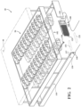
- FIG. 2 schematically depicts an illustrative parking facility of the parking facility communication system of FIG. 1 according to one or more embodiments described and illustrated herein;
- FIG. 3 schematically depicts a block diagram of illustrative components of the computing network for the parking facility communication system of FIG. 1 according to one or more embodiments shown or described herein;
- FIG. 4 depicts a flowchart of an illustrative method of a user initiating a human request for entrance into or to exit the example parking facility of FIG. 2 according to one or more embodiments shown and described herein.
- a gate assembly includes a gate controller that operably controls a gate via a gate actuator and a gate receiver/transmitter device.
- the parking facility includes a peripheral device, such as a long range receiver/transmitter device, and a gateway device.
- the gate controller, the peripheral device and the gateway device are each configured to wirelessly communicate amongst one another using an ultra-wide band protocol or a long range wide area network protocol.
- the communication system includes a remote server computing device positioned offsite of the parking facility.
- the term “communication” and/or “communicatively coupled” means that coupled components are capable of exchanging data signals and/or electric signals with one another such as, for example, data signals transmitted wirelessly, electrical signals via conductive medium, electromagnetic signals via air, optical signals, via optical waveguides electrical energy via conductive medium or a non-conductive medium, and the like.
- minimally interferes means that the construction material of the gate assembly, the parking facility, vehicles, and the like, does not prevent the transmission of data between an on-site controller and an offsite remote sever, as shown in Table 1 below, compared with a wireless internet, WI-Fi, and the like, as shown in table 2 below. That is, while the construction material of the gate assembly, the parking facility, vehicles, and the like, may weaken, distort, change or modify the transmission standards and/or power standards of the wireless transmission such as a wireless data, a power, and/or electrical signals, utilizing ultra-wide band protocols, long range wide area network protocols, narrowband-internet of things protocols, and/or Sigfox protocols, permits the transmission of data through these environments.
- the weaken signal of the ultra-wide band, long range wide area network, narrowband-internet of things, and/or Sigfox protocols is significantly less than weaken signal of Wi-fi, Internet, cellular service, and the like.
- Wi-fi, Internet, cellular service, and the like cannot transmit or receive data from an offsite server based on a weak and/or significantly reduced signal strength, as shown in Table 2 below, while the ultra-wide band, long range wide area network, narrowband-internet of things, and/or Sigfox protocols are able to transmit and receive data, as illustrated in Table 1 below.
- the scanned values gathered using the long range wide area network protocol and the Wi-Fi protocol were gathered from a gate controller positioned inside a gate housing and within a parking faculty.
- RSSI is the received signal strength indicator
- SNR is a signal to noise ratio
- sf spreading factor
- the RSSI is approximately 30 dB
- the SNR is 0 dB
- the signal level is approximately 100/100 dB in the Wi-Fi network protocol without any interference.
- a narrowband-internet of things (NB-IoT) protocol or a Sigfox protocol is utilized as the wireless communication protocol between the remote server computing device 40 and the various components of the example parking facility 20 .
- the NB-IoT protocol may be a narrowband cellular-grade wireless technology that may send and receive small amounts of data.
- Sigfox may be a narrowband or ultra-narrowband technology that uses a standard radio transmission such as binary phase-shift keying (BPSK) and utilizes narrow chunks of spectrum and changes the phase of the carrier radio wave to encode the data. This allows the receiver to only listen in a tiny slice of spectrum, which mitigates the effect of noise.
- Sigfox communication may be bidirectional.
- the example parking facility 20 may employ Bluetooth® and the like, for the purposes of identifying the vehicle 50 , a user via the user interface device 60 , and the like, as discussed in greater detail herein. Further, in some embodiments, the example parking facility 20 and/or components thereof may perform one or more computing functions, such as receiving data, capturing image data, processing data, storing data and the like, for permitting a vehicle access into or to exit the parking facility, as described in greater detail herein.
- the vehicle 50 may generally be any vehicle with one or more onboard computing devices, particularly computing devices that contain hardware for receiving data, processing data, storing data, and/or transmitting data.
- the vehicle 50 and/or components thereof may perform one or more computing functions, such as receiving data, capturing image data, processing data, storing data and the like for identifying the vehicle and/or providing unique vehicle identification information data (e.g., license plates, VIN, and the like), such that the vehicle may be granted access or exit authorization from the example parking facility 20 , as described in greater detail herein.
- unique vehicle identification information data e.g., license plates, VIN, and the like
- the user interface device 60 may generally be used as an interface between the user and the other components connected to the illustrative communication system 10 , such as the example parking facility 20 .
- the user interface device 60 may be used to perform one or more user-facing functions, such as receiving one or more inputs from the user or providing information to the user, as described in greater detail herein.
- the user interface device 60 may include at least a display and/or input hardware.
- the user interface device 60 may be used to input data into the illustrative communication system 10 and components thereof, such as the example parking facility 20 .
- the user interface device 60 may request for entry or exit authorization from the example parking facility 20 , as discussed in greater detail herein.
- the user interface device 60 may contain software programming that relates to determining the location of the user (i.e., at which gate of the example parking facility for those that have more than one entry and/or exit locations), syncing with the example parking facility 20 or components thereof, and the like.
- the remote server computing device 40 is positioned offsite from the example parking facility 20 and may receive data from one or more sources, generate data, store data, index data, and/or provide data to the gateway device 30 and/or the example parking facility 20 (or components thereof).
- “offsite” as used herein means that the remote server computing device 40 is located at some other place other than at the example parking facility 20 and thus wirelessly communicates with the example parking facility 20 (or components thereof).
- the remote server computing device 40 is positioned in a different building, a different complex, a different compound, or beyond a particular distance (e.g., more than 100 feet, 100 yards, or the like). As such, in some embodiments, it should be understood that the remote server computing device 40 is not in the same vicinity as the example parking facility 20 .
- the remote server computing device 40 may employ one or more algorithms that are used for the purposes of analyzing data that is received from the vehicle 50 , the user interface device 60 , the example parking facility 20 , and the like, such as whether the vehicle at the parking facility 20 is authorized to enter and/or exit the example parking facility 20 , and the like. As such, it should be appreciated that the remote server computing device 40 may function with the example parking facility 20 (or components thereof) and/or vehicles to employ the one or more algorithms.
- the remote server computing device 40 off-loads some of the computing processes from the example parking facility 20 (or components thereof) onto other components within the illustrative communication system 10 .
- components of the example parking facility 20 includes an on-premise computing device 105 , such as a gate controller, that is communicatively coupled to the remote server computing device 40 , as discussed in greater detail herein.
- the term “on-premise” means that the computing device 105 is located within a general vicinity of the example parking facility 20 .
- the on-premise computing device 105 may be located in the same facility, in the same building, in the same complex, in the same compound, within a particular distance (e.g., within 100 feet, 100 yards, or the like).
- “on-premise” specifically excludes remote server computing devices that are not in the same vicinity of the example parking facility 20 .
- the peripheral device 110 is an on-premise device.
- a second communications connection B communications between the user interface device 60 or the vehicle 50 and the on-premise computing device 105 is indicated by a second communications connection B.
- the second communications connection B is via a Bluetooth® protocol, a wired connection, and the like.
- a third communications connection C between the gateway device 30 and the remote server computing device 40 is wireless and uses the UWB protocol, the LoRa protocol, the NB-IoT protocol, the six fox protocol, and/or another known or yet to be known protocol.
- the first communications connection A and the third communications connection C are identical and data is transferred between the first communications connection A and the third communications connection C using the UWB protocol, the LoRa protocol, the NB-IoT protocol, the Sigfox protocol, and/or another known or yet to be known protocol.
- the gateway device 30 may receive and forward an instructional signal to the gate controller 105 via the peripheral device 110 to provide an instruction to move a gate 125 of the parking facility 20 into the open position and allow the user and the vehicle 50 to enter or exit the example parking facility 20 .
- the example parking facility 20 is constructed of a steel frame, rebar, concrete, cement, and/or other construction materials that inherently affect traditional Wi-Fi, internet, and other wireless signals and/or data transmission. As such, it is difficult to use wireless communication in or at the parking facility 20 without interference from the construction materials. This creates an unreliable wireless connection.
- the gate controller 105 may receive and/or transmit a plurality of local signals (e.g. from the vehicle 50 and/or the user interface device 60 of FIG. 1 ). Further, the gate controller 105 may receive and/or transmit a plurality of wireless long range signals. In some embodiments, the plurality of wireless long range signals are generated from the gate controller 105 and terminate at the remote server computing device 40 ( FIG. 1 ), as discussed in greater detail herein. In other embodiments, the plurality of wireless long range signals are generated from the remote server computing device 40 ( FIG. 1 ) and terminate at the gate controller 105 , as discussed in greater detail herein. In either embodiment, the wireless long range signals may be transmitted through the various components of the example parking facility 20 using UWB, LoRa®, NB-IoT, and/or Sigfox protocols.
- the gate assembly 100 further includes a quick response (QR) device 140 that is communicatively coupled to the gate controller 105 .
- the QR device 140 may be any commercially available device that is configured to read and/or scan unique QR codes, barcodes, and the like. As such, it should be appreciated that the QR device 140 may assist in identifying the vehicle and/or the user by transmitting or outputting a unique code to the gate controller 105 , which in turn may communicate with the remote server computing device 40 ( FIG. 1 ) to determine whether the vehicle and/or the user is authorized to enter and/or exit the example parking facility 20 , as discussed in greater detail herein.
- the at least one image capturing device 150 may include or may be coupled to a lens (not shown).
- the lens is not limited by this disclosure and may generally be any optical component that is configured to focus the light entering the at least one image capturing device 150 such that an image can be properly obtained.
- the lens may be a fixed lens that is not adjustable.
- the lens may be adjustable, either manually or automatically by the gate controller 105 , to zoom in on an object, zoom out on an object, and/or adjust the focus of the light entering the at least one image capturing device 150 .
- the memory component 305 may be configured as a volatile and/or a nonvolatile computer-readable medium and, as such, may include random access memory (including SRAM, DRAM, and/or other types of random access memory), read only memory (ROM), flash memory, registers, compact discs (CD), digital versatile discs (DVD), and/or other types of storage components. Further, the memory component 305 may be a non-transitory, processor-readable memory. The memory component 305 may include one or more programming instructions thereon that, when executed by the processor device 320 , cause the processor device 320 to complete various processes, such as one or more of the processes described herein with respect to FIG. 4 .
- the programming instructions stored on the memory component 305 may be embodied as the one or more software logic modules 325 , where each logic module 325 provides programming instructions for completing one or more tasks, as described in greater detail below with respect to FIG. 4 .
- the logic module 325 includes a plurality of different pieces of logic, each of which may be embodied as a computer program, firmware, and/or software/hardware, which may be executable by the processor device 320 .
- the logic module 325 may include a plurality of different pieces of logic with respect to transmitting received local signals (i.e., those form the vehicle detection/identification sensor 135 , the QR device 140 , and the at least one image capturing device 150 of FIG.
- the logic module 325 may include a plurality of different pieces of logic with respect to actuating the gate actuator 120 ( FIG. 2 ).
- the network interface hardware 315 may include any wired or wireless networking hardware, such as a modem, a LAN port, a wireless fidelity (Wi-Fi) card, WiMax card, mobile communications hardware, antenna, and/or other hardware for communicating with other networks and/or devices.
- the network interface hardware 315 may provide a wireless communications link between the gate controller 105 and the other components of the communication system 10 ( FIG. 1 ) such as the gateway device 30 , the peripheral device 110 ( FIG. 2 ), the remote server computing device 40 , and the like.
- the transmitted and/or received signal may be transformed into a data signal indicative of a gate command, whether access is permitted to allow the vehicle 50 to enter and/or exit the example parking facility 20 ( FIG. 2 ), and the like. It should be appreciated that other data may transmitted and/or received such as identification data, entry and exit time, payment data, and the like.
- the vehicle detection/identification sensor 135 , the QR device 140 , and/or the at least one image capturing device 150 may be communicatively coupled to the gate controller 105 .
- the vehicle detection/identification sensor 135 , the QR device 140 , and/or the at least one image capturing device 150 ( FIG. 2 ) may be configured to capture unique identification of the vehicle 50 ( FIG. 1 ), the user, the user interface device 60 ( FIG. 1 ), and the like.
- unique identification may be a parking permit, a license plate, a barcode, and/or other unique identifiers.
- the vehicle detection/identification sensor 135 , the QR device 140 , and/or the at least one image capturing device 150 ( FIG. 2 ) output captured data to the gate controller 105 , as a vehicle detection/identification sensor data 330 , a QR device data 335 , and at least one image capturing device data 340 .
- the gate controller 105 processes the received data and then wirelessly transmits the pertinent data of the identification data to the remote server computing device 40 , via the gateway device 30 , to verify whether the data is authorized. It should be appreciated that, in some embodiments, the gate controller 105 and components thereof, may not transfer all the captured identification data, but instead, due to the constraints of the UWB protocol the LoRa® protocol, the NB-IoT protocol, and/or Sigfox protocol, determine the most pertinent data of the identification data and transmit that data only. It should be understood that as the UWB protocol, the LoRa® protocol, the NB-IoT protocol, and/or the Sigfox protocol improve in data transfer capabilities, more of the identification data may be transmitted.
- the data storage device 310 may store a gate data 345 .
- the gate data 345 may be data related to the gate 125 ( FIG. 2 ) such as whether the gate 125 ( FIG. 2 ) is currently in the open or closed position, a type of gate, a mounting or coupling position of the gate (e.g., whether the gate is a pivot type, a slide type, and the like).
- the data storage device 310 may also store information or data received from the remote server computing device 40 such as a gate command in the gate data 345 .
- the gate command may be an instruction or command to open or close the gate 125 ( FIG. 2 ) based on a determination at the remote server computing device 40 , as discussed in greater detail herein.
- the remote server computing device 40 may include, but is not limited to, a memory component 355 , a data storage device 360 , a network interface 370 and a processor device 375 .
- a local interface 380 such as a bus or the like, may interconnect the various components.
- the memory component 355 may be configured as a volatile and/or a nonvolatile computer-readable medium and, as such, may include random access memory (including SRAM, DRAM, and/or other types of random access memory), read only memory (ROM), flash memory, registers, compact discs (CD), digital versatile discs (DVD), and/or other types of storage components. Further, the memory component 355 may be a non-transitory, processor-readable memory. The memory component 355 may include one or more programming instructions thereon that, when executed by the processor device 375 , cause the processor device 375 to complete various processes, such as one or more of the processes described herein with respect to FIG. 4 .
- the programming instructions stored on the memory component 355 may be embodied as the one or more software logic modules 360 , where each logic module 360 provides programming instructions for completing one or more tasks, as described in greater detail below with respect to FIG. 4 .
- the logic module 360 includes a plurality of different pieces of logic, each of which may be embodied as a computer program, firmware, and/or software/hardware, which may be executable by the processor device 375 .
- the logic module 360 may include a plurality of different pieces of logic with respect interpreting received wireless data transmissions from the gate controller 105 (i.e., received local signals from the vehicle detection/identification sensor 135 , the QR device 140 , and the at least one image capturing device 150 ) using the wireless long range protocols (i.e., UWB, LoRa®, NB-IoT, and/or Sigfox).
- the wireless long range protocols i.e., UWB, LoRa®, NB-IoT, and/or Sigfox.
- the logic module 360 may include a plurality of different pieces of logic to determine whether the data transmitted by the gate controller 105 pertains to an authorized vehicle or user such that the gate 125 ( FIG. 2 ) of the parking facility 20 ( FIG. 2 ) should be moved into the open position.
- the logic module 360 may include a plurality of different pieces of logic to transmit the gate command to the gate controller 105 to move the gate 125 ( FIG. 2 ) into the open or closed positions.
- the network interface hardware 370 may include any wired or wireless networking hardware, such as a modem, a LAN port, a wireless fidelity (Wi-Fi) card, WiMax card, mobile communications hardware, antenna, and/or other hardware for communicating with other networks and/or devices.
- the network interface hardware 370 may provide a wireless communications link between the remote server computing device 40 and the other components of the communication system 10 ( FIG. 1 ) such as the gateway device 30 , the peripheral device 110 ( FIG. 2 ), the gate controller 105 , and the like. That is, in embodiments, the network interface hardware 370 is configured to transmit from the remote server computing device 40 to other components of the communication system 10 ( FIG.
- the gateway device 30 receives signals from other components of the communication system 10 ( FIG. 1 ) (e.g., the gateway device 30 , the peripheral device 110 ( FIG. 2 ), the gate controller 105 , and the like) using the UWB protocol, the LoRa® protocol, the NB-IoT protocol, and/or the Sigfox protocol.
- the transmitted and/or received communications may be transformed into a data signal indicative of a gate command, whether access is permitted to allow the vehicle 50 to enter and/or exit the example parking facility 20 ( FIG. 2 ), and the like. It should be appreciated that other data may transmitted and/or received such as identification data, entry and exit time, payment data, and the like.
- the network interface hardware 370 is configured to transmit and receive data between the remote server computing device 40 and the administrative user computing device 80 via the network 70 .
- the administrative user computing device 80 may update the various components of the remote server computing device 40 with data related to authorized vehicles and/or users, stored payment information, and the like.
- the data storage device 365 of the remote server computing device 40 may store information or data related to the unique identification of the vehicle 50 ( FIG. 1 ), the user, the user interface device 60 ( FIG. 1 ), and the like.
- unique identification may be a parking permit, a license plate, a barcode, and/or other unique identifiers.
- the data storage device 365 may be cross referenced to determine whether the received unique information corresponds to an authorized vehicle or user.
- the data storage device 365 may store data related to the number of entries and exits, the capacity of the parking facility 20 ( FIG. 2 ), payment information, peak times of entry and exit, and the like. Further, data related to the gate 125 ( FIG. 2 ) may be stored in the data storage device 365 such as whether the gate 125 ( FIG. 2 ) is currently in the open or closed position, a type of gate, a mounting or coupling position of the gate (e.g., whether the gate is a pivot type, a slide type, and the like), the amount of time it is taking for the gate to open and close for maintenance purposes, and the like.
- the various components described with respect to FIG. 3 may be used to carry out one or more processes for parking facility communication system that enables wireless communication from the parking facility to a remote server computing device regardless of the construction material of the gated parking facility and without structural modifications to the parking facility.
- FIG. 4 a flowchart of an illustrative method 400 of requesting to enter and/or exit the parking facility is schematically depicted.
- the gate controller, the gateway and the remote server computing device may all be in continuous communication to execute the various steps depicted in FIG. 4 .
- the various components may monitor for a user input that corresponds to an initiation for entry into or to exit the gated parking facility, such as the user initiates a request via the user interface or the QR device, at block 405 .
- the user may use a software application on the user interface to initiate the request to enter and/or exit the parking facility using Bluetooth® protocol.
- the peripheral device wirelessly transmits the authorization request to the gateway device using the UWB protocol, the LoRa® protocol, the NB-IoT protocol, and/or the Sigfox protocol, at block 420 and the gateway device wirelessly transmits the authorization request to the remote server computing device using the UWB protocol, the LoRa® protocol, the NB-IoT protocol, and/or the Sigfox protocol, at block 425 .
- the remote server computing device uses the pertinent data of the information data to verify whether the request is for an authorized user or vehicle and a gate open request is authorized. For example, the remote server computing device may verify a registration, a reservation, and the like utilizing the pertinent data of the information data. In another example, the remote server computing device may verify a successful payment for entry or exit of the parking facility.
- the remote server computing device determines whether the gate open request is authorized. If the gate open request is not authorized at block 435 , the method 400 ends at block 440 .
- the remote server computing device transmits a gate command to the peripheral device via the gateway device using the UWB protocol, the LoRa® protocol, the NB-IoT protocol, and/or the Sigfox protocol, at block 445 .
- the gate open command is communicated with the gate controller from the peripheral device, at block 450 , and, in response, the gate is moved into an open position at block 455 .
Landscapes
- Physics & Mathematics (AREA)
- General Physics & Mathematics (AREA)
- Engineering & Computer Science (AREA)
- Computer Networks & Wireless Communication (AREA)
- Signal Processing (AREA)
- Business, Economics & Management (AREA)
- Finance (AREA)
- Devices For Checking Fares Or Tickets At Control Points (AREA)
- Traffic Control Systems (AREA)
Abstract
Description
| TABLE 1 | |||||
| LoRaWAN | Spread Factor | RSSI (dB) | SNR (dB) | ||
| Sf10 | −95 | 4 | |||
| Sf10 | −115 | −4 | |||
| Sf12 | −95 | 4 | |||
| Sf12 | −110 | 3 | |||
| Sf8 | −99 | 0 | |||
| TABLE 2 | ||||
| Protocol | Frequency | Signal Level (dB) | ||
| IEEE 802.11AC | 5.745 GHz | 13/100 | ||
| IEEE 802.11i/WPA2 Version 1 | ||||
| IEEE 802.11bgn | 2.412 |
19/100 | ||
| IEEE 802 11i/WPA2 Version 1 | ||||
| IEEE 802.11bgn | 2.462 GHz | 14/100 | ||
| IEEE 802 11i/WPA2 Version 1 | ||||
| IEEE 802.11AC | 5.18 GHz | 12/100 | ||
| IEEE 802.11i/WPA2 Version 1 | ||||
| IEEE 802.11AC | 5.785 GHz | 14/100 | ||
| IEEE 802.11i/WPA2 Version 1 | ||||
Claims (17)
Priority Applications (1)
| Application Number | Priority Date | Filing Date | Title |
|---|---|---|---|
| US16/988,112 US11842591B2 (en) | 2019-08-07 | 2020-08-07 | Parking facility communication systems and methods |
Applications Claiming Priority (2)
| Application Number | Priority Date | Filing Date | Title |
|---|---|---|---|
| US201962883972P | 2019-08-07 | 2019-08-07 | |
| US16/988,112 US11842591B2 (en) | 2019-08-07 | 2020-08-07 | Parking facility communication systems and methods |
Publications (2)
| Publication Number | Publication Date |
|---|---|
| US20210043021A1 US20210043021A1 (en) | 2021-02-11 |
| US11842591B2 true US11842591B2 (en) | 2023-12-12 |
Family
ID=74498969
Family Applications (1)
| Application Number | Title | Priority Date | Filing Date |
|---|---|---|---|
| US16/988,112 Active US11842591B2 (en) | 2019-08-07 | 2020-08-07 | Parking facility communication systems and methods |
Country Status (1)
| Country | Link |
|---|---|
| US (1) | US11842591B2 (en) |
Cited By (1)
| Publication number | Priority date | Publication date | Assignee | Title |
|---|---|---|---|---|
| US20240080668A1 (en) * | 2022-09-07 | 2024-03-07 | Bank Of America Corporation | Communication, Authentication, and Validation Using LoRaWAN Protocol |
Families Citing this family (3)
| Publication number | Priority date | Publication date | Assignee | Title |
|---|---|---|---|---|
| CN113015136B (en) * | 2021-03-31 | 2022-08-26 | 广州文远知行科技有限公司 | Parking network switching method and device, movable carrier and storage medium |
| US12192870B1 (en) * | 2021-05-20 | 2025-01-07 | Orbcomm, Inc. | System, method and apparatus for non-invasive sensor configuration and networking |
| PL4198929T3 (en) * | 2021-12-16 | 2024-04-22 | Blokado Sp. Z O. O. | A system for controlling a parking space lock and a method for controlling a parking space lock |
Citations (27)
| Publication number | Priority date | Publication date | Assignee | Title |
|---|---|---|---|---|
| US20110099126A1 (en) * | 2005-08-30 | 2011-04-28 | Sensact Applications, Inc. | Automated Parking Policy Enforcement System |
| US20120143657A1 (en) * | 2010-12-03 | 2012-06-07 | Cds Worldwide Pty Ltd | Parking system and method |
| US20120143401A1 (en) * | 2010-12-06 | 2012-06-07 | PES School of Engineering | Vehicle Management System |
| US20120173900A1 (en) * | 2010-11-03 | 2012-07-05 | Broadcom Corporation | Providing power over ethernet within a vehicular communication network |
| US20120191242A1 (en) * | 2010-03-02 | 2012-07-26 | Christopher Scott Outwater | Method and apparatus for finding and accessing a vehicle fueling station, including an electric vehicle charging station |
| US20140213176A1 (en) * | 2005-04-12 | 2014-07-31 | Ehud Mendelson | Vehicle wireless |
| US20140365359A1 (en) * | 2013-01-23 | 2014-12-11 | Clyde Bartlett Wilson | Alternative customer tracking for parking facilities |
| US20150138001A1 (en) * | 2013-11-18 | 2015-05-21 | ImageMaker Development Inc. | Automated parking space management system with dynamically updatable display device |
| US20160042575A1 (en) * | 2014-08-11 | 2016-02-11 | Locomobi, Inc. | Automated facility access and payment processing systems and methods |
| US20160140846A1 (en) * | 2014-09-25 | 2016-05-19 | Christopher Scott Outwater | System and Method for Parking Management Based on Location Tracking |
| US20160163197A1 (en) * | 2013-07-26 | 2016-06-09 | Anagog Ltd. | Parking occupancy estimation |
| US20170098374A1 (en) * | 2015-10-05 | 2017-04-06 | Parkifi, Inc. | Parking data aggregation and distribution |
| US20170116790A1 (en) * | 2015-10-22 | 2017-04-27 | Collateral Opportunities, Llc | Method and system for an automated parking system |
| CN106657612A (en) * | 2016-11-28 | 2017-05-10 | 深圳市捷隽科技有限公司 | Wireless networking cloud access control system and method for implementing mobile phone talkback door opening |
| US20170345305A1 (en) * | 2016-05-27 | 2017-11-30 | Qiufeng Zheng | Method and apparatus for internet based smart parking space optimization |
| US9997070B1 (en) * | 2017-05-18 | 2018-06-12 | Abl Ip Holding Llc | Use of software configurable luminaire in parking application |
| US20180248983A1 (en) * | 2016-12-21 | 2018-08-30 | Ncore Communications, Inc. | Methods and apparatus for aggregating network access within a single unified platform for a myriad of devices |
| US20190043356A1 (en) * | 2017-08-01 | 2019-02-07 | Duncan Parking Technologies, Inc. | Advanced parking management system |
| CN107993478B (en) | 2017-09-15 | 2019-05-03 | 路特迩科技(杭州)有限公司 | Berth service and management system and method based on vehicle detection |
| US20190147743A1 (en) * | 2017-11-14 | 2019-05-16 | GM Global Technology Operations LLC | Vehicle guidance based on location spatial model |
| US10326518B1 (en) * | 2018-03-09 | 2019-06-18 | Mueller International, Llc | Repeater and node utilization |
| US20190215369A1 (en) * | 2018-01-09 | 2019-07-11 | Stel Life, Inc. | Secure Wireless Communication Platform |
| US20190224509A1 (en) * | 2018-01-23 | 2019-07-25 | Tyco Fire Products Lp | System and method for monitoring and controlling a fire suppression system |
| US10543809B1 (en) * | 2018-10-04 | 2020-01-28 | Dish Network L.L.C. | Systems and methods for identifying unauthorized vehicle use |
| US20200090515A1 (en) * | 2016-12-09 | 2020-03-19 | Rumbo Mobile Inc. | System and method for monitoring occupancy at each of a plurality of locations |
| US20200242934A1 (en) * | 2019-01-24 | 2020-07-30 | Here Global B.V. | Dual mode indoor parking data delivery and map integration |
| US20200365021A1 (en) * | 2017-11-09 | 2020-11-19 | Clarion Co., Ltd. | Vehicle-mounted device, recording medium, and notification method |
-
2020
- 2020-08-07 US US16/988,112 patent/US11842591B2/en active Active
Patent Citations (27)
| Publication number | Priority date | Publication date | Assignee | Title |
|---|---|---|---|---|
| US20140213176A1 (en) * | 2005-04-12 | 2014-07-31 | Ehud Mendelson | Vehicle wireless |
| US20110099126A1 (en) * | 2005-08-30 | 2011-04-28 | Sensact Applications, Inc. | Automated Parking Policy Enforcement System |
| US20120191242A1 (en) * | 2010-03-02 | 2012-07-26 | Christopher Scott Outwater | Method and apparatus for finding and accessing a vehicle fueling station, including an electric vehicle charging station |
| US20120173900A1 (en) * | 2010-11-03 | 2012-07-05 | Broadcom Corporation | Providing power over ethernet within a vehicular communication network |
| US20120143657A1 (en) * | 2010-12-03 | 2012-06-07 | Cds Worldwide Pty Ltd | Parking system and method |
| US20120143401A1 (en) * | 2010-12-06 | 2012-06-07 | PES School of Engineering | Vehicle Management System |
| US20140365359A1 (en) * | 2013-01-23 | 2014-12-11 | Clyde Bartlett Wilson | Alternative customer tracking for parking facilities |
| US20160163197A1 (en) * | 2013-07-26 | 2016-06-09 | Anagog Ltd. | Parking occupancy estimation |
| US20150138001A1 (en) * | 2013-11-18 | 2015-05-21 | ImageMaker Development Inc. | Automated parking space management system with dynamically updatable display device |
| US20160042575A1 (en) * | 2014-08-11 | 2016-02-11 | Locomobi, Inc. | Automated facility access and payment processing systems and methods |
| US20160140846A1 (en) * | 2014-09-25 | 2016-05-19 | Christopher Scott Outwater | System and Method for Parking Management Based on Location Tracking |
| US20170098374A1 (en) * | 2015-10-05 | 2017-04-06 | Parkifi, Inc. | Parking data aggregation and distribution |
| US20170116790A1 (en) * | 2015-10-22 | 2017-04-27 | Collateral Opportunities, Llc | Method and system for an automated parking system |
| US20170345305A1 (en) * | 2016-05-27 | 2017-11-30 | Qiufeng Zheng | Method and apparatus for internet based smart parking space optimization |
| CN106657612A (en) * | 2016-11-28 | 2017-05-10 | 深圳市捷隽科技有限公司 | Wireless networking cloud access control system and method for implementing mobile phone talkback door opening |
| US20200090515A1 (en) * | 2016-12-09 | 2020-03-19 | Rumbo Mobile Inc. | System and method for monitoring occupancy at each of a plurality of locations |
| US20180248983A1 (en) * | 2016-12-21 | 2018-08-30 | Ncore Communications, Inc. | Methods and apparatus for aggregating network access within a single unified platform for a myriad of devices |
| US9997070B1 (en) * | 2017-05-18 | 2018-06-12 | Abl Ip Holding Llc | Use of software configurable luminaire in parking application |
| US20190043356A1 (en) * | 2017-08-01 | 2019-02-07 | Duncan Parking Technologies, Inc. | Advanced parking management system |
| CN107993478B (en) | 2017-09-15 | 2019-05-03 | 路特迩科技(杭州)有限公司 | Berth service and management system and method based on vehicle detection |
| US20200365021A1 (en) * | 2017-11-09 | 2020-11-19 | Clarion Co., Ltd. | Vehicle-mounted device, recording medium, and notification method |
| US20190147743A1 (en) * | 2017-11-14 | 2019-05-16 | GM Global Technology Operations LLC | Vehicle guidance based on location spatial model |
| US20190215369A1 (en) * | 2018-01-09 | 2019-07-11 | Stel Life, Inc. | Secure Wireless Communication Platform |
| US20190224509A1 (en) * | 2018-01-23 | 2019-07-25 | Tyco Fire Products Lp | System and method for monitoring and controlling a fire suppression system |
| US10326518B1 (en) * | 2018-03-09 | 2019-06-18 | Mueller International, Llc | Repeater and node utilization |
| US10543809B1 (en) * | 2018-10-04 | 2020-01-28 | Dish Network L.L.C. | Systems and methods for identifying unauthorized vehicle use |
| US20200242934A1 (en) * | 2019-01-24 | 2020-07-30 | Here Global B.V. | Dual mode indoor parking data delivery and map integration |
Non-Patent Citations (1)
| Title |
|---|
| S. A. A'ssri, F. H. K. Zaman and S. Mubdi, "The efficient parking bay allocation and management system using LoRaWAN," 2017 IEEE 8th Control and System Graduate Research Colloquium (ICSGRC), Shah Alam, 2017, pp. 127-131, doi: 10.1109/ICSGRC.2017.8070581. |
Cited By (2)
| Publication number | Priority date | Publication date | Assignee | Title |
|---|---|---|---|---|
| US20240080668A1 (en) * | 2022-09-07 | 2024-03-07 | Bank Of America Corporation | Communication, Authentication, and Validation Using LoRaWAN Protocol |
| US12335734B2 (en) * | 2022-09-07 | 2025-06-17 | Bank Of America Corporation | Communication, authentication, and validation using LoRaWAN protocol |
Also Published As
| Publication number | Publication date |
|---|---|
| US20210043021A1 (en) | 2021-02-11 |
Similar Documents
| Publication | Publication Date | Title |
|---|---|---|
| US11842591B2 (en) | Parking facility communication systems and methods | |
| US11335130B2 (en) | Method for checking toll transactions and components therefor | |
| EP4194056A1 (en) | Stopper-type charging device and driving method thereof | |
| CN105405296A (en) | Vehicle passage control system and method based on license plate identification | |
| CN111465955A (en) | Method and apparatus for managing shared vehicles | |
| CN111295568B (en) | Method and device for determining a spatial division of an environment | |
| US12445808B2 (en) | System, method and computer program for a monitoring system | |
| CN105763594A (en) | Information push method and device | |
| CA2980476A1 (en) | System, method and computer program for an access control system | |
| JP7765112B2 (en) | Electronic payment agent system and program that can handle electronic payments for systems that cannot handle electronic payments | |
| KR102463760B1 (en) | Service providing apparatus for providing sharing situation of camper | |
| KR102108001B1 (en) | Recording Medium, Device and Method for Processing Parking Fee by Using Message | |
| CN105528641A (en) | Method for carrying out visit appointment based on local address book, terminal and server | |
| KR102429515B1 (en) | System for parking management based mobile terminal | |
| KR20170113486A (en) | Wireless parking system and real-time car information sharing method using the same | |
| US20240394860A1 (en) | Method and electronic device for parking lot operation based on depth map and for flooding prediction using learning model | |
| KR20220025566A (en) | Sharing system of parking zone | |
| KR20160146258A (en) | System and method for parking fee payment | |
| KR102463758B1 (en) | Service providing system for sharing a camper | |
| KR20190119945A (en) | Smart car in-and-out management system | |
| KR20170049917A (en) | Method and Apparatus for Managing the Vehicle Image | |
| US20180158002A1 (en) | Secure method and system for verification management and control of event seat-rights | |
| KR102108004B1 (en) | Recording Medium, Device and Method for Processing Parking Fee by Using Message | |
| KR100686550B1 (en) | Designated parking management system with parking prevention device and its operation method | |
| KR102212673B1 (en) | Method, system and computer program for parking management using digital key for vehicle |
Legal Events
| Date | Code | Title | Description |
|---|---|---|---|
| AS | Assignment |
Owner name: SPOTHERO, INC., ILLINOIS Free format text: ASSIGNMENT OF ASSIGNORS INTEREST;ASSIGNOR:SVITAK, GREGORY STEPHEN;REEL/FRAME:053435/0957 Effective date: 20200806 |
|
| FEPP | Fee payment procedure |
Free format text: ENTITY STATUS SET TO UNDISCOUNTED (ORIGINAL EVENT CODE: BIG.); ENTITY STATUS OF PATENT OWNER: LARGE ENTITY |
|
| STPP | Information on status: patent application and granting procedure in general |
Free format text: DOCKETED NEW CASE - READY FOR EXAMINATION |
|
| STPP | Information on status: patent application and granting procedure in general |
Free format text: NON FINAL ACTION MAILED |
|
| STPP | Information on status: patent application and granting procedure in general |
Free format text: RESPONSE TO NON-FINAL OFFICE ACTION ENTERED AND FORWARDED TO EXAMINER |
|
| STPP | Information on status: patent application and granting procedure in general |
Free format text: FINAL REJECTION MAILED |
|
| STPP | Information on status: patent application and granting procedure in general |
Free format text: DOCKETED NEW CASE - READY FOR EXAMINATION |
|
| STPP | Information on status: patent application and granting procedure in general |
Free format text: NON FINAL ACTION MAILED |
|
| STPP | Information on status: patent application and granting procedure in general |
Free format text: RESPONSE TO NON-FINAL OFFICE ACTION ENTERED AND FORWARDED TO EXAMINER |
|
| STPP | Information on status: patent application and granting procedure in general |
Free format text: NON FINAL ACTION MAILED |
|
| STPP | Information on status: patent application and granting procedure in general |
Free format text: FINAL REJECTION MAILED |
|
| STPP | Information on status: patent application and granting procedure in general |
Free format text: DOCKETED NEW CASE - READY FOR EXAMINATION |
|
| STPP | Information on status: patent application and granting procedure in general |
Free format text: NOTICE OF ALLOWANCE MAILED -- APPLICATION RECEIVED IN OFFICE OF PUBLICATIONS |
|
| STPP | Information on status: patent application and granting procedure in general |
Free format text: PUBLICATIONS -- ISSUE FEE PAYMENT RECEIVED |
|
| STPP | Information on status: patent application and granting procedure in general |
Free format text: PUBLICATIONS -- ISSUE FEE PAYMENT VERIFIED |
|
| STCF | Information on status: patent grant |
Free format text: PATENTED CASE |