US11833103B2 - Hip joint link apparatus - Google Patents
Hip joint link apparatus Download PDFInfo
- Publication number
- US11833103B2 US11833103B2 US17/154,086 US202117154086A US11833103B2 US 11833103 B2 US11833103 B2 US 11833103B2 US 202117154086 A US202117154086 A US 202117154086A US 11833103 B2 US11833103 B2 US 11833103B2
- Authority
- US
- United States
- Prior art keywords
- link
- joint
- linked
- revolute
- revolute joint
- Prior art date
- Legal status (The legal status is an assumption and is not a legal conclusion. Google has not performed a legal analysis and makes no representation as to the accuracy of the status listed.)
- Active, expires
Links
- 210000004394 hip joint Anatomy 0.000 title claims abstract description 68
- 210000000689 upper leg Anatomy 0.000 claims abstract description 30
- 210000001503 joint Anatomy 0.000 claims abstract description 16
- 230000008878 coupling Effects 0.000 claims description 42
- 238000010168 coupling process Methods 0.000 claims description 42
- 238000005859 coupling reaction Methods 0.000 claims description 42
- 230000007246 mechanism Effects 0.000 description 12
- 230000005021 gait Effects 0.000 description 11
- 210000002414 leg Anatomy 0.000 description 4
- 230000005540 biological transmission Effects 0.000 description 3
- 230000008901 benefit Effects 0.000 description 1
- 230000008859 change Effects 0.000 description 1
- 230000000694 effects Effects 0.000 description 1
- 210000001624 hip Anatomy 0.000 description 1
- 238000012423 maintenance Methods 0.000 description 1
- 238000012986 modification Methods 0.000 description 1
- 230000004048 modification Effects 0.000 description 1
Images


Classifications
-
- A—HUMAN NECESSITIES
- A61—MEDICAL OR VETERINARY SCIENCE; HYGIENE
- A61H—PHYSICAL THERAPY APPARATUS, e.g. DEVICES FOR LOCATING OR STIMULATING REFLEX POINTS IN THE BODY; ARTIFICIAL RESPIRATION; MASSAGE; BATHING DEVICES FOR SPECIAL THERAPEUTIC OR HYGIENIC PURPOSES OR SPECIFIC PARTS OF THE BODY
- A61H1/00—Apparatus for passive exercising; Vibrating apparatus; Chiropractic devices, e.g. body impacting devices, external devices for briefly extending or aligning unbroken bones
- A61H1/02—Stretching or bending or torsioning apparatus for exercising
- A61H1/0237—Stretching or bending or torsioning apparatus for exercising for the lower limbs
- A61H1/0244—Hip
-
- B—PERFORMING OPERATIONS; TRANSPORTING
- B25—HAND TOOLS; PORTABLE POWER-DRIVEN TOOLS; MANIPULATORS
- B25J—MANIPULATORS; CHAMBERS PROVIDED WITH MANIPULATION DEVICES
- B25J9/00—Programme-controlled manipulators
- B25J9/0006—Exoskeletons, i.e. resembling a human figure
-
- A—HUMAN NECESSITIES
- A61—MEDICAL OR VETERINARY SCIENCE; HYGIENE
- A61H—PHYSICAL THERAPY APPARATUS, e.g. DEVICES FOR LOCATING OR STIMULATING REFLEX POINTS IN THE BODY; ARTIFICIAL RESPIRATION; MASSAGE; BATHING DEVICES FOR SPECIAL THERAPEUTIC OR HYGIENIC PURPOSES OR SPECIFIC PARTS OF THE BODY
- A61H3/00—Appliances for aiding patients or disabled persons to walk about
-
- B—PERFORMING OPERATIONS; TRANSPORTING
- B25—HAND TOOLS; PORTABLE POWER-DRIVEN TOOLS; MANIPULATORS
- B25J—MANIPULATORS; CHAMBERS PROVIDED WITH MANIPULATION DEVICES
- B25J9/00—Programme-controlled manipulators
- B25J9/003—Programme-controlled manipulators having parallel kinematics
- B25J9/0045—Programme-controlled manipulators having parallel kinematics with kinematics chains having a rotary joint at the base
- B25J9/0048—Programme-controlled manipulators having parallel kinematics with kinematics chains having a rotary joint at the base with kinematics chains of the type rotary-rotary-rotary
-
- A—HUMAN NECESSITIES
- A61—MEDICAL OR VETERINARY SCIENCE; HYGIENE
- A61H—PHYSICAL THERAPY APPARATUS, e.g. DEVICES FOR LOCATING OR STIMULATING REFLEX POINTS IN THE BODY; ARTIFICIAL RESPIRATION; MASSAGE; BATHING DEVICES FOR SPECIAL THERAPEUTIC OR HYGIENIC PURPOSES OR SPECIFIC PARTS OF THE BODY
- A61H3/00—Appliances for aiding patients or disabled persons to walk about
- A61H2003/007—Appliances for aiding patients or disabled persons to walk about secured to the patient, e.g. with belts
-
- A—HUMAN NECESSITIES
- A61—MEDICAL OR VETERINARY SCIENCE; HYGIENE
- A61H—PHYSICAL THERAPY APPARATUS, e.g. DEVICES FOR LOCATING OR STIMULATING REFLEX POINTS IN THE BODY; ARTIFICIAL RESPIRATION; MASSAGE; BATHING DEVICES FOR SPECIAL THERAPEUTIC OR HYGIENIC PURPOSES OR SPECIFIC PARTS OF THE BODY
- A61H2201/00—Characteristics of apparatus not provided for in the preceding codes
- A61H2201/16—Physical interface with patient
- A61H2201/1602—Physical interface with patient kind of interface, e.g. head rest, knee support or lumbar support
- A61H2201/1628—Pelvis
- A61H2201/163—Pelvis holding means therefor
-
- A—HUMAN NECESSITIES
- A61—MEDICAL OR VETERINARY SCIENCE; HYGIENE
- A61H—PHYSICAL THERAPY APPARATUS, e.g. DEVICES FOR LOCATING OR STIMULATING REFLEX POINTS IN THE BODY; ARTIFICIAL RESPIRATION; MASSAGE; BATHING DEVICES FOR SPECIAL THERAPEUTIC OR HYGIENIC PURPOSES OR SPECIFIC PARTS OF THE BODY
- A61H2201/00—Characteristics of apparatus not provided for in the preceding codes
- A61H2201/16—Physical interface with patient
- A61H2201/1602—Physical interface with patient kind of interface, e.g. head rest, knee support or lumbar support
- A61H2201/164—Feet or leg, e.g. pedal
- A61H2201/1642—Holding means therefor
-
- A—HUMAN NECESSITIES
- A61—MEDICAL OR VETERINARY SCIENCE; HYGIENE
- A61H—PHYSICAL THERAPY APPARATUS, e.g. DEVICES FOR LOCATING OR STIMULATING REFLEX POINTS IN THE BODY; ARTIFICIAL RESPIRATION; MASSAGE; BATHING DEVICES FOR SPECIAL THERAPEUTIC OR HYGIENIC PURPOSES OR SPECIFIC PARTS OF THE BODY
- A61H2201/00—Characteristics of apparatus not provided for in the preceding codes
- A61H2201/16—Physical interface with patient
- A61H2201/1602—Physical interface with patient kind of interface, e.g. head rest, knee support or lumbar support
- A61H2201/165—Wearable interfaces
- A61H2201/1652—Harness
-
- A—HUMAN NECESSITIES
- A61—MEDICAL OR VETERINARY SCIENCE; HYGIENE
- A61H—PHYSICAL THERAPY APPARATUS, e.g. DEVICES FOR LOCATING OR STIMULATING REFLEX POINTS IN THE BODY; ARTIFICIAL RESPIRATION; MASSAGE; BATHING DEVICES FOR SPECIAL THERAPEUTIC OR HYGIENIC PURPOSES OR SPECIFIC PARTS OF THE BODY
- A61H2201/00—Characteristics of apparatus not provided for in the preceding codes
- A61H2201/16—Physical interface with patient
- A61H2201/1657—Movement of interface, i.e. force application means
- A61H2201/1676—Pivoting
Definitions
- a hip joint link apparatus is provided.
- a hip joint is an important part that allows a body to move forward while balancing an upper body when walking. Recently, it has been proven that gait ability of a user is improved when appropriate hip joint moment assistance is applied to a user wearing a wearable robot.
- the moment of the hip joint applied to the human body is largely divided into the moments of flexion and extension, and abduction and adduction, and the direction of the required moment is changed depending on gait phases.
- one actuator per leg assists flexion moment and extension moment, or two actuators per leg assist flexion moment and extension moment, and abduction moment and adduction moment.
- the present invention has been made in an effort to provide a hip joint link apparatus of a wearable robot that may assist torques of which direction is varying between flexion/extension and abduction/adduction depending on gait phases when a user wearing a wearable robot walks even if only one actuator per leg is used.
- An embodiment of the present invention provides a hip joint link apparatus including: an upper body link fixed to an upper body of a wearable robot, and a hip joint jointer linking a thigh link to a thigh of the wearable robot, wherein the hip joint jointer includes a four-bar linkage structure including a plurality of revolute joints and a plurality of links; an arbitrary input moment to the hip joint jointer is changed to an output moment in a predetermined direction based on a state of being transmitted to the plurality of links through the plurality of revolute joints; and the hip joint jointer assists a flexion moment, an extension moment, an abduction moment, and an adduction moment.
- the plurality of revolute joints may include: a first revolute joint that is linked to the upper body link and functions as a rotation axis of an input moment, a second revolute joint that is interlocked at one side thereof to rotation of the first revolute joint, a third revolute joint that is interlocked to rotation of the second revolute joint, a fourth revolute joint that is interlocked to rotation of the third revolute joint, a fifth revolute joint that is provided at a position spaced apart from the second revolute joint by a predetermined distance and is interlocked at the other side thereof to rotation of the first revolute joint, and a sixth revolute joint that is linked to the thigh link and is interlocked to rotation of the third revolute joint.
- the plurality of links may include: a first link linked to the upper body link through the first revolute joint, a second link linked to the first link through the second revolute joint, a third link linked to the first link through the fifth revolute joint, and a fourth link linked to the second link through the third revolute joint and linked to the third link through the fourth revolute joint.
- the thigh link may be linked to the fourth link through the sixth revolute joint.
- the first link may include an eleventh coupling part that is linked to a lower portion of the upper body link to have a pivotable central support structure, a twelfth coupling part wherein an end portion thereof that is bent from the eleventh coupling part in a predetermined direction to extend is linked to one side of the second link, and a thirteenth coupling part wherein an end portion thereof that is spaced apart from the twelfth coupling part from the eleventh coupling part by a predetermined distance to extend in a direction of the third link is linked to one side of the third link.
- the fourth link may include a forty-first coupling part that has a pivotable central support structure and is linked to the other side of the second link, a forty-second coupling part wherein an end portion thereof extending in a predetermined direction from the forty-first coupling part is linked to an upper portion of the thigh link, and a forty-third coupling part wherein an end portion thereof that is spaced apart from the forty-second coupling part from the forty-first coupling part by a predetermined distance to extend in a direction of the third link is linked to the other of the third link.
- the hip joint link apparatus may further include at least one driving part, wherein the driving part may be linked to the first revolute joint.
- the hip joint link apparatus may assist flexion, extension, abduction, and adduction moments required when a user wearing the wearable robot walks.
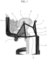
- FIG. 1 illustrates a schematic view of a hip joint link apparatus according to an embodiment of the present invention.
- FIG. 2 illustrates the same series link mechanism instantaneously in terms of a force transmission relationship with a hip joint link apparatus according to an embodiment of the present invention.
- FIG. 3 is a drawing in which a sixth virtual link and output moments are accumulated when a thigh link linked to a thigh of a wearable robot has a gait motion.
- FIG. 4 illustrates dimensions of the hip joint link apparatus according to an embodiment of the present invention.
- FIG. 5 illustrates various aspects of a user wearing a hip joint link apparatus according to an embodiment of the present invention.
- FIG. 6 illustrates a walking situation after a user wears a prototype of a hip joint link apparatus according to an embodiment of the present invention.
- FIG. 7 illustrates a state viewed from the top of FIG. 6 .
- FIG. 8 illustrates a state in which a user wears a trial product of a hip joint link apparatus according to an embodiment of the present invention.
- FIG. 9 illustrates a moment profile that is changed when a hip joint link apparatus according to an embodiment of the present invention is applied.
- FIG. 1 illustrate a schematic view of a hip joint link apparatus according to an embodiment of the present invention
- FIG. 2 illustrates the same series link mechanism instantaneously in terms of a force transmission relationship with a hip joint link apparatus according to an embodiment of the present invention
- FIG. 3 is a drawing in which a sixth virtual link and output moments are accumulated when a thigh link linked to a thigh of a wearable robot has a gait motion
- FIG. 4 illustrates dimensions of the hip joint link apparatus according to an embodiment of the present invention.
- a hip joint link apparatus includes a hip joint jointer linking an upper body link 10 fixed to an upper body of a wearable robot and a thigh link 15 linked to a thigh.
- a hip joint jointer linking an upper body link 10 fixed to an upper body of a wearable robot and a thigh link 15 linked to a thigh.
- the hip joint part includes a plurality of revolute joints and a plurality of links linking the upper body link 10 fixed to the upper body of the wearable robot and the thigh link 15 linked to the thigh.
- a revolute joint and a link corresponding to each other may be linked to each other, so that a four-revolute joint link mechanism capable of changing an output moment direction may be implemented.
- an arbitrary input moment is changed to an output moment in a predetermined direction based on a state in which the arbitrary input moment is transmitted to the plurality of links through the plurality of revolute joints, so that the hip joint jointer may assist the required flexion, extension, abduction, and adduction direction moments when the wearable robot walks.
- the plurality of revolute joints may include a first revolute joint 1 , a second revolute joint 2 , a third revolute joint 3 , a fourth revolute joint 4 , and a fifth revolute joint 5 , sixth revolute joint 6 .
- the first revolute joint 1 may be linked to the upper body link 10 to function as a revolute axis of the input moment.
- the hip joint link apparatus includes at least one driving part, and the driving part may be linked to the first revolute joint 1 .
- One side of the second revolute joint 2 may be interlocked to revolution of the first revolute joint 1 .
- the third revolute joint 3 may be interlocked to revolution of the second revolute joint 2 .
- the fourth revolute joint 4 may be interlocked to revolution of the third revolute joint 3 .
- the fifth revolute joint 5 is provided at a position spaced apart from the second revolute joint 2 by a predetermined distance to be interlocked to the revolution of the first revolute joint 1 at the other side thereof.
- the sixth revolute joint 6 is linked to the thigh link 15 , and may be interlocked to the revolution of the third revolute joint 3 .
- the plurality of links may include a first link 11 , a second link 12 , a third link 13 , and a fourth link 14 .
- the first link 11 may be linked to the upper body link 10 through the first revolute joint 1 .
- the first link 11 may include an eleventh coupling part 11 a , a twelfth coupling part 11 b , and a thirteenth coupling part 11 c .
- the eleventh coupling part 11 a is linked to a lower portion of the upper body link 10 to have a pivotable central support structure.
- An end portion of the twelfth coupling part 11 b that is bent in a predetermined direction in the eleventh coupling part 11 a to extend is linked to one side of the second link 12 .
- An end portion of the thirteenth coupling part 11 c that is spaced apart from the twelfth coupling part 11 b by a predetermined distance at the eleventh coupling part 11 a to extend in a direction of the third link 13 is linked to one side of the third link 13 .
- the second link 12 may be linked to the first link 11 through the second revolute joint 2 .
- the third link 13 may be linked to the first link 11 through the fifth revolute joint 5 .
- the fourth link 14 may be linked to the second link 12 through the third revolute joint 3 , and may be linked to the third link 13 through the fourth revolute joint 4 .
- the fourth link 14 may include a forty-first coupling part 14 a , a forty-second coupling part 14 b , and a forty-third coupling part 14 c.
- the forty-first coupling part 14 a has a pivotable central support structure, and is linked to the other side of the second link 12 .
- An end portion of the forty-second coupling part 14 b that extends in a predetermined direction from the forty-first coupling part 14 a is linked to the upper portion of the thigh link 15 .
- An end portion of the forty-third coupling part 14 c that is formed to be spaced apart from the forty-second coupling part 14 b by a predetermined distance from the forty-first coupling part 14 a to extend in a direction of the third link 13 is linked to the other side of the third link 13 .
- the thigh link 15 may be linked to the fourth link 14 through the sixth revolute joint 6 .
- the hip joint jointer includes the first revolute joint 1 , the second revolute joint 2 , the third revolute joint 3 , the fourth revolute joint 4 , the fifth revolute joint 5 , the sixth revolute joint 6 , the first link 11 , the second link 12 , the third link 13 , and the fourth link 14 , and accordingly, it may be applied to the hip joint link apparatus by implementing the four-bar linkage mechanism.
- the four-bar linkage mechanism including the plurality of revolute joints and the plurality of links receives the input moment of the driving part by using the hip joint jointer according to the embodiment of the present invention, a direction thereof may be changed to the corresponding output moment.
- a desirable momentum direction may be implemented by a serial connection structure between the four-bar linkage mechanism and the revolute joint.
- FIG. 2 illustrates the same series link mechanism instantaneously in terms of a force transmission relationship with a hip joint link apparatus according to an embodiment of the present invention.
- a position of a virtual revolute joint 7 of a serial link mechanism at the right side of FIG. 2 is the same as a position of an instantaneous rotation axis 0 defined in a mechanism at the left side thereof.
- the instantaneous rotation axis 0 means an instantaneous rotation axis of the fourth link 14 with respect to the first link 11 .
- a sixth virtual link 16 is a virtual link that links the virtual revolute joint 7 and the sixth revolute joint 6 .
- the moment inputted in the direction of the first revolute joint 1 through the driving part may be transmitted to the thigh link 15 as a moment having an axis in a direction perpendicular to the sixth virtual link 16 through the hip joint link apparatus.
- FIG. 3 is a drawing in which the sixth virtual link 16 and output moments are accumulated when the thigh link 15 linked to the thigh of the wearable robot has a gait motion.
- the hip joint link apparatus proposed in the embodiment of the present invention may output a moment in a different direction according to a gait phase in a state in which there is no moment of a rotation component during the gait motion of the wearable robot.
- a moment obtained by adding an extension moment and an abduction moment may be outputted in an initial stance.
- An abduction moment may be outputted in a mid stance.
- a moment of a sum of a flexion moment and an abduction moment may be outputted in a terminal stance.
- FIG. 4 illustrates a link relationship and dimensions of the hip joint link apparatus according to an embodiment of the present invention. Referring to FIG. 4 , it is possible to see an angle of a revolute joint axis using a spherical coordinate.
- FIG. 5 illustrates various aspects of a user wearing a hip joint link apparatus according to an embodiment of the present invention.
- FIG. 5 illustrates a state in which a user actually wears the hip joint link apparatus according to the embodiment of the present invention, and accordingly, the user may previously grasp the wearing state of the hip joint link apparatus.
- FIG. 6 illustrates a walking situation after a user wears a prototype of a hip joint link apparatus according to an embodiment of the present invention.
- FIG. 7 illustrates a state viewed from the top of FIG. 6 . Referring to FIG. 6 and FIG. 7 , it can be seen that the output moment direction is changed according to the leg position when the wearer with the wearable robot is walking.
- an input moment axis 30 may be positioned at the rotation axis of the first revolute joint 1 .
- the rotation axis of the fourth link 14 with respect to the first link 11 is the instantaneous rotation axis 0 .
- An output moment axis 20 may be in a vertical direction simultaneously to the instantaneous rotation axis 0 , and a rotation axis 60 of the sixth revolute joint 6 .
- FIG. 8 illustrates a state in which a user wears a trial product of a hip joint link apparatus according to an embodiment of the present invention.
- the output moment direction is changed according to the user's gait phase. As described above, the direction of “extension moment+abduction moment” is outputted in the initial stance of walking, the direction of abduction moment is outputted in the mid stance, and the direction of “flexion moment+abduction moment” is outputted in the terminal stance.
- FIG. 9 illustrates a biological moment profile of a wearer that is changed when a hip joint link apparatus according to an embodiment of the present invention is applied.
- the driving part is applied to the first revolute joint 1
- an example of the moment profile transmitted to the thigh of the wearable robot through the thigh link 15 is shown.
- the reduced moment may be grasped in advance.
- the moment profile of adduction (Add.)/abduction (Abd.) directions is given similar to the human body moment profile in the background art
- the moment profile of flexion (Flex.)/extension (Ext.) and rotation which are the other two directions, is also shown in a form similar to the human body moment profile in the background art.
- a three-dimensional moment profile required for gait may be outputted even though only one driving part is used.
- the hip joint link apparatus according to the embodiment of the present invention provides the feature that could not be realized in the design of any conventional hip joint link apparatus. Accordingly, when the outputted three-dimensional moment profile is applied to the human body, as shown in the right side of FIG. 9 , it is possible to reduce both the flexion/extension direction moment and the adduction/abduction direction moment. This feature may be realized only when two or more driving parts are applied in a conventional hip mechanism design.
- the hip joint link apparatus since the hip joint link apparatus according to the embodiment of the present invention includes a plurality of revolute joints and a plurality of links, productivity is good and maintenance is easy. In addition, since it is possible to realize the effect of using a plurality of driving units while reducing the number of driving parts, a more inexpensive wearable robot may be developed, and a commercially available time point of the wearable robot may be accelerated.
Landscapes
- Health & Medical Sciences (AREA)
- Engineering & Computer Science (AREA)
- Physical Education & Sports Medicine (AREA)
- Epidemiology (AREA)
- Pain & Pain Management (AREA)
- Rehabilitation Therapy (AREA)
- Life Sciences & Earth Sciences (AREA)
- Animal Behavior & Ethology (AREA)
- General Health & Medical Sciences (AREA)
- Public Health (AREA)
- Veterinary Medicine (AREA)
- Mechanical Engineering (AREA)
- Robotics (AREA)
- Rehabilitation Tools (AREA)
- Manipulator (AREA)
Abstract
Description
Claims (7)
Applications Claiming Priority (4)
| Application Number | Priority Date | Filing Date | Title |
|---|---|---|---|
| KR20200071805 | 2020-06-12 | ||
| KR10-2020-0071805 | 2020-06-12 | ||
| KR10-2020-0136264 | 2020-10-20 | ||
| KR1020200136264A KR102464399B1 (en) | 2020-06-12 | 2020-10-20 | Hip mechanism |
Publications (2)
| Publication Number | Publication Date |
|---|---|
| US20210386610A1 US20210386610A1 (en) | 2021-12-16 |
| US11833103B2 true US11833103B2 (en) | 2023-12-05 |
Family
ID=78824207
Family Applications (1)
| Application Number | Title | Priority Date | Filing Date |
|---|---|---|---|
| US17/154,086 Active 2041-09-28 US11833103B2 (en) | 2020-06-12 | 2021-01-21 | Hip joint link apparatus |
Country Status (2)
| Country | Link |
|---|---|
| US (1) | US11833103B2 (en) |
| CN (1) | CN113799096B (en) |
Citations (17)
| Publication number | Priority date | Publication date | Assignee | Title |
|---|---|---|---|---|
| US5020790A (en) | 1990-10-23 | 1991-06-04 | Board Of Supervisors Of Louisiana State University And Agricultural And Mechanical College | Powered gait orthosis |
| US20060213305A1 (en) * | 2003-04-24 | 2006-09-28 | Thomas Sugar | Adjustable compliant mechanism |
| US20140330431A1 (en) * | 2013-05-06 | 2014-11-06 | Springactive, Inc. | Joint Torque Augmentation System and Method for Gait Assistance |
| US20150134080A1 (en) * | 2013-11-14 | 2015-05-14 | Samsung Electronics Co., Ltd. | Wearable robot and method for controlling the same |
| US20150321340A1 (en) | 2014-05-06 | 2015-11-12 | Sarcos Lc | Legged Robotic Device Utilizing Modifiable Linkage Mechanism |
| CN106333830A (en) | 2016-09-20 | 2017-01-18 | 合肥工业大学 | Walking aiding mechanism of lower limb rehabilitation robot |
| WO2017167349A1 (en) | 2016-03-31 | 2017-10-05 | Aalborg Universitet | Spherical joint mechanism with a double parallelogram mechanism |
| KR20180068805A (en) | 2016-12-14 | 2018-06-22 | 현대자동차주식회사 | Suspension system for vehicle |
| KR101948261B1 (en) | 2018-10-31 | 2019-02-14 | 서울대학교산학협력단 | Finger rehabilitation exercise guide apparatus |
| WO2019076417A1 (en) | 2017-10-17 | 2019-04-25 | Aalborg Universitet | Compact spherical 3-dof mechanism constructed with scissor linkages |
| US20190232485A1 (en) | 2016-06-27 | 2019-08-01 | Marcel Reese | Exoskeleton and master |
| US20190240524A1 (en) * | 2018-04-15 | 2019-08-08 | Rezvan Nasiri | Methods and systems for an exoskeleton to reduce a runners metabolic rate |
| KR102016859B1 (en) | 2018-06-27 | 2019-08-30 | 한양대학교 에리카산학협력단 | Walking aid apparatus |
| CN110251365A (en) | 2019-06-12 | 2019-09-20 | 中北大学 | A kind of spherical surface ectoskeleton hip joint healing mechanism |
| KR102032500B1 (en) | 2018-11-12 | 2019-11-08 | 국방과학연구소 | Walking assist apparatus |
| CN110666783A (en) | 2019-11-20 | 2020-01-10 | 北京工业大学 | Hip joint exoskeleton assistance mechanism |
| KR102213377B1 (en) | 2019-08-14 | 2021-02-08 | 국민대학교산학협력단 | Robot legs structure for high speed and high torque |
-
2021
- 2021-01-21 US US17/154,086 patent/US11833103B2/en active Active
- 2021-05-08 CN CN202110499359.8A patent/CN113799096B/en active Active
Patent Citations (18)
| Publication number | Priority date | Publication date | Assignee | Title |
|---|---|---|---|---|
| US5020790A (en) | 1990-10-23 | 1991-06-04 | Board Of Supervisors Of Louisiana State University And Agricultural And Mechanical College | Powered gait orthosis |
| US20060213305A1 (en) * | 2003-04-24 | 2006-09-28 | Thomas Sugar | Adjustable compliant mechanism |
| US20140330431A1 (en) * | 2013-05-06 | 2014-11-06 | Springactive, Inc. | Joint Torque Augmentation System and Method for Gait Assistance |
| US20150134080A1 (en) * | 2013-11-14 | 2015-05-14 | Samsung Electronics Co., Ltd. | Wearable robot and method for controlling the same |
| US20150321340A1 (en) | 2014-05-06 | 2015-11-12 | Sarcos Lc | Legged Robotic Device Utilizing Modifiable Linkage Mechanism |
| WO2017167349A1 (en) | 2016-03-31 | 2017-10-05 | Aalborg Universitet | Spherical joint mechanism with a double parallelogram mechanism |
| US20190232485A1 (en) | 2016-06-27 | 2019-08-01 | Marcel Reese | Exoskeleton and master |
| CN106333830A (en) | 2016-09-20 | 2017-01-18 | 合肥工业大学 | Walking aiding mechanism of lower limb rehabilitation robot |
| KR20180068805A (en) | 2016-12-14 | 2018-06-22 | 현대자동차주식회사 | Suspension system for vehicle |
| US20200238542A1 (en) * | 2017-10-17 | 2020-07-30 | Aalborg Universitet | Compact spherical 3-dof mechanism constructed with scissor linkages |
| WO2019076417A1 (en) | 2017-10-17 | 2019-04-25 | Aalborg Universitet | Compact spherical 3-dof mechanism constructed with scissor linkages |
| US20190240524A1 (en) * | 2018-04-15 | 2019-08-08 | Rezvan Nasiri | Methods and systems for an exoskeleton to reduce a runners metabolic rate |
| KR102016859B1 (en) | 2018-06-27 | 2019-08-30 | 한양대학교 에리카산학협력단 | Walking aid apparatus |
| KR101948261B1 (en) | 2018-10-31 | 2019-02-14 | 서울대학교산학협력단 | Finger rehabilitation exercise guide apparatus |
| KR102032500B1 (en) | 2018-11-12 | 2019-11-08 | 국방과학연구소 | Walking assist apparatus |
| CN110251365A (en) | 2019-06-12 | 2019-09-20 | 中北大学 | A kind of spherical surface ectoskeleton hip joint healing mechanism |
| KR102213377B1 (en) | 2019-08-14 | 2021-02-08 | 국민대학교산학협력단 | Robot legs structure for high speed and high torque |
| CN110666783A (en) | 2019-11-20 | 2020-01-10 | 北京工业大学 | Hip joint exoskeleton assistance mechanism |
Also Published As
| Publication number | Publication date |
|---|---|
| CN113799096B (en) | 2024-05-17 |
| CN113799096A (en) | 2021-12-17 |
| US20210386610A1 (en) | 2021-12-16 |
Similar Documents
| Publication | Publication Date | Title |
|---|---|---|
| US11819428B2 (en) | Semi-active robotic joint | |
| KR101986933B1 (en) | Forward or rearward oriented exoskeleton | |
| KR101073525B1 (en) | Wearable robot for assisting the muscular strength of lower extremity | |
| US10583551B2 (en) | Exoskeleton and method of increasing the flexibility of an exoskeleton joint | |
| CN106924013B (en) | Exoskeleton type upper limb rehabilitation training robot | |
| Cempini et al. | Self-alignment mechanisms for assistive wearable robots: A kinetostatic compatibility method | |
| US9604369B2 (en) | Exoskeleton and method of increasing the flexibility of an exoskeleton hip joint | |
| US10350130B2 (en) | Universal tensegrity joints for human exoskeleton | |
| WO2014045433A1 (en) | Joint movement device | |
| Bartenbach et al. | Concept and design of a modular lower limb exoskeleton | |
| Li et al. | Structure design of lower limb exoskeletons for gait training | |
| EP2981240B1 (en) | Mechanical linkage | |
| Kuan et al. | Design of a knee joint mechanism that adapts to individual physiology | |
| US11833103B2 (en) | Hip joint link apparatus | |
| KR102633470B1 (en) | Wearable Assistance Device | |
| Yang et al. | Simulation of exoskeleton ZMP during walking for balance control | |
| KR102464399B1 (en) | Hip mechanism | |
| Shin et al. | Optimal design of multi-linked knee joint for lower limb wearable robot | |
| US20230073133A1 (en) | Knee joint guide apparatus | |
| Pasbanian et al. | Design and Fabrication of an Ankle Rehabilitation Robot with Active Dorsiflexion-Plantarflexion Control and Free Eversion-Inversion Motion | |
| BARBU | Virtual prototyping for an mechatronics device used for medical rehabilitation | |
| JP2010063722A (en) | Muscular strength assisting instrument |
Legal Events
| Date | Code | Title | Description |
|---|---|---|---|
| AS | Assignment |
Owner name: SEOUL NATIONAL UNIVERSITY R&DB FOUNDATION, KOREA, REPUBLIC OF Free format text: ASSIGNMENT OF ASSIGNORS INTEREST;ASSIGNORS:KANG, SEOK WON;KIM, YOON YOUNG;REEL/FRAME:054982/0136 Effective date: 20201105 |
|
| FEPP | Fee payment procedure |
Free format text: ENTITY STATUS SET TO UNDISCOUNTED (ORIGINAL EVENT CODE: BIG.); ENTITY STATUS OF PATENT OWNER: SMALL ENTITY |
|
| FEPP | Fee payment procedure |
Free format text: ENTITY STATUS SET TO SMALL (ORIGINAL EVENT CODE: SMAL); ENTITY STATUS OF PATENT OWNER: SMALL ENTITY |
|
| STPP | Information on status: patent application and granting procedure in general |
Free format text: DOCKETED NEW CASE - READY FOR EXAMINATION |
|
| STPP | Information on status: patent application and granting procedure in general |
Free format text: NON FINAL ACTION MAILED |
|
| STPP | Information on status: patent application and granting procedure in general |
Free format text: FINAL REJECTION MAILED |
|
| STPP | Information on status: patent application and granting procedure in general |
Free format text: NOTICE OF ALLOWANCE MAILED -- APPLICATION RECEIVED IN OFFICE OF PUBLICATIONS |
|
| STPP | Information on status: patent application and granting procedure in general |
Free format text: AWAITING TC RESP., ISSUE FEE NOT PAID |
|
| STPP | Information on status: patent application and granting procedure in general |
Free format text: NOTICE OF ALLOWANCE MAILED -- APPLICATION RECEIVED IN OFFICE OF PUBLICATIONS |
|
| STPP | Information on status: patent application and granting procedure in general |
Free format text: PUBLICATIONS -- ISSUE FEE PAYMENT VERIFIED |
|
| STCF | Information on status: patent grant |
Free format text: PATENTED CASE |