US11830897B2 - Square-gate source-follower for CMOS image sensor pixel - Google Patents
Square-gate source-follower for CMOS image sensor pixel Download PDFInfo
- Publication number
- US11830897B2 US11830897B2 US17/141,141 US202117141141A US11830897B2 US 11830897 B2 US11830897 B2 US 11830897B2 US 202117141141 A US202117141141 A US 202117141141A US 11830897 B2 US11830897 B2 US 11830897B2
- Authority
- US
- United States
- Prior art keywords
- gate
- source
- region
- doped region
- drain
- Prior art date
- Legal status (The legal status is an assumption and is not a legal conclusion. Google has not performed a legal analysis and makes no representation as to the accuracy of the status listed.)
- Active, expires
Links
- 239000004065 semiconductor Substances 0.000 claims abstract description 13
- 238000002955 isolation Methods 0.000 claims description 19
- 239000000758 substrate Substances 0.000 claims description 12
- 229910021420 polycrystalline silicon Inorganic materials 0.000 claims description 4
- 229920005591 polysilicon Polymers 0.000 claims description 4
- VYPSYNLAJGMNEJ-UHFFFAOYSA-N Silicium dioxide Chemical compound O=[Si]=O VYPSYNLAJGMNEJ-UHFFFAOYSA-N 0.000 claims 2
- 235000012239 silicon dioxide Nutrition 0.000 claims 1
- 239000000377 silicon dioxide Substances 0.000 claims 1
- 238000000034 method Methods 0.000 abstract description 7
- 230000000295 complement effect Effects 0.000 abstract description 5
- 229910044991 metal oxide Inorganic materials 0.000 abstract description 5
- 150000004706 metal oxides Chemical class 0.000 abstract description 5
- 230000010354 integration Effects 0.000 abstract description 3
- 230000007423 decrease Effects 0.000 description 11
- 238000003384 imaging method Methods 0.000 description 6
- 238000004519 manufacturing process Methods 0.000 description 6
- 230000003247 decreasing effect Effects 0.000 description 4
- XUIMIQQOPSSXEZ-UHFFFAOYSA-N Silicon Chemical compound [Si] XUIMIQQOPSSXEZ-UHFFFAOYSA-N 0.000 description 3
- 238000005516 engineering process Methods 0.000 description 3
- 230000003287 optical effect Effects 0.000 description 3
- 230000008569 process Effects 0.000 description 3
- 229910052710 silicon Inorganic materials 0.000 description 3
- 239000010703 silicon Substances 0.000 description 3
- 238000006243 chemical reaction Methods 0.000 description 2
- 238000010586 diagram Methods 0.000 description 2
- 230000000694 effects Effects 0.000 description 2
- 238000012986 modification Methods 0.000 description 2
- 230000004048 modification Effects 0.000 description 2
- 229910052581 Si3N4 Inorganic materials 0.000 description 1
- 230000002411 adverse Effects 0.000 description 1
- 230000008901 benefit Effects 0.000 description 1
- 230000001419 dependent effect Effects 0.000 description 1
- 230000008021 deposition Effects 0.000 description 1
- 230000009977 dual effect Effects 0.000 description 1
- 230000005684 electric field Effects 0.000 description 1
- 230000005669 field effect Effects 0.000 description 1
- 239000007943 implant Substances 0.000 description 1
- 238000009413 insulation Methods 0.000 description 1
- 230000000670 limiting effect Effects 0.000 description 1
- 239000000463 material Substances 0.000 description 1
- 230000036961 partial effect Effects 0.000 description 1
- 230000009467 reduction Effects 0.000 description 1
- 230000002829 reductive effect Effects 0.000 description 1
- 235000002020 sage Nutrition 0.000 description 1
Images


Classifications
-
- H01L27/14614—
-
- H01L27/14603—
-
- H01L27/14616—
-
- H01L27/14643—
-
- H—ELECTRICITY
- H04—ELECTRIC COMMUNICATION TECHNIQUE
- H04N—PICTORIAL COMMUNICATION, e.g. TELEVISION
- H04N25/00—Circuitry of solid-state image sensors [SSIS]; Control thereof
- H04N25/70—SSIS architectures; Circuits associated therewith
- H04N25/76—Addressed sensors, e.g. MOS or CMOS sensors
-
- H—ELECTRICITY
- H10—SEMICONDUCTOR DEVICES; ELECTRIC SOLID-STATE DEVICES NOT OTHERWISE PROVIDED FOR
- H10F—INORGANIC SEMICONDUCTOR DEVICES SENSITIVE TO INFRARED RADIATION, LIGHT, ELECTROMAGNETIC RADIATION OF SHORTER WAVELENGTH OR CORPUSCULAR RADIATION
- H10F39/00—Integrated devices, or assemblies of multiple devices, comprising at least one element covered by group H10F30/00, e.g. radiation detectors comprising photodiode arrays
- H10F39/10—Integrated devices
- H10F39/12—Image sensors
- H10F39/18—Complementary metal-oxide-semiconductor [CMOS] image sensors; Photodiode array image sensors
-
- H—ELECTRICITY
- H10—SEMICONDUCTOR DEVICES; ELECTRIC SOLID-STATE DEVICES NOT OTHERWISE PROVIDED FOR
- H10F—INORGANIC SEMICONDUCTOR DEVICES SENSITIVE TO INFRARED RADIATION, LIGHT, ELECTROMAGNETIC RADIATION OF SHORTER WAVELENGTH OR CORPUSCULAR RADIATION
- H10F39/00—Integrated devices, or assemblies of multiple devices, comprising at least one element covered by group H10F30/00, e.g. radiation detectors comprising photodiode arrays
- H10F39/80—Constructional details of image sensors
- H10F39/802—Geometry or disposition of elements in pixels, e.g. address-lines or gate electrodes
- H10F39/8023—Disposition of the elements in pixels, e.g. smaller elements in the centre of the imager compared to larger elements at the periphery
-
- H—ELECTRICITY
- H10—SEMICONDUCTOR DEVICES; ELECTRIC SOLID-STATE DEVICES NOT OTHERWISE PROVIDED FOR
- H10F—INORGANIC SEMICONDUCTOR DEVICES SENSITIVE TO INFRARED RADIATION, LIGHT, ELECTROMAGNETIC RADIATION OF SHORTER WAVELENGTH OR CORPUSCULAR RADIATION
- H10F39/00—Integrated devices, or assemblies of multiple devices, comprising at least one element covered by group H10F30/00, e.g. radiation detectors comprising photodiode arrays
- H10F39/80—Constructional details of image sensors
- H10F39/803—Pixels having integrated switching, control, storage or amplification elements
- H10F39/8037—Pixels having integrated switching, control, storage or amplification elements the integrated elements comprising a transistor
- H10F39/80373—Pixels having integrated switching, control, storage or amplification elements the integrated elements comprising a transistor characterised by the gate of the transistor
-
- H—ELECTRICITY
- H10—SEMICONDUCTOR DEVICES; ELECTRIC SOLID-STATE DEVICES NOT OTHERWISE PROVIDED FOR
- H10F—INORGANIC SEMICONDUCTOR DEVICES SENSITIVE TO INFRARED RADIATION, LIGHT, ELECTROMAGNETIC RADIATION OF SHORTER WAVELENGTH OR CORPUSCULAR RADIATION
- H10F39/00—Integrated devices, or assemblies of multiple devices, comprising at least one element covered by group H10F30/00, e.g. radiation detectors comprising photodiode arrays
- H10F39/80—Constructional details of image sensors
- H10F39/803—Pixels having integrated switching, control, storage or amplification elements
- H10F39/8037—Pixels having integrated switching, control, storage or amplification elements the integrated elements comprising a transistor
- H10F39/80377—Pixels having integrated switching, control, storage or amplification elements the integrated elements comprising a transistor characterised by the channel of the transistor, e.g. channel having a doping gradient
-
- H—ELECTRICITY
- H10—SEMICONDUCTOR DEVICES; ELECTRIC SOLID-STATE DEVICES NOT OTHERWISE PROVIDED FOR
- H10F—INORGANIC SEMICONDUCTOR DEVICES SENSITIVE TO INFRARED RADIATION, LIGHT, ELECTROMAGNETIC RADIATION OF SHORTER WAVELENGTH OR CORPUSCULAR RADIATION
- H10F39/00—Integrated devices, or assemblies of multiple devices, comprising at least one element covered by group H10F30/00, e.g. radiation detectors comprising photodiode arrays
- H10F39/80—Constructional details of image sensors
- H10F39/804—Containers or encapsulations
-
- H—ELECTRICITY
- H10—SEMICONDUCTOR DEVICES; ELECTRIC SOLID-STATE DEVICES NOT OTHERWISE PROVIDED FOR
- H10F—INORGANIC SEMICONDUCTOR DEVICES SENSITIVE TO INFRARED RADIATION, LIGHT, ELECTROMAGNETIC RADIATION OF SHORTER WAVELENGTH OR CORPUSCULAR RADIATION
- H10F39/00—Integrated devices, or assemblies of multiple devices, comprising at least one element covered by group H10F30/00, e.g. radiation detectors comprising photodiode arrays
- H10F39/80—Constructional details of image sensors
- H10F39/807—Pixel isolation structures
-
- H—ELECTRICITY
- H10—SEMICONDUCTOR DEVICES; ELECTRIC SOLID-STATE DEVICES NOT OTHERWISE PROVIDED FOR
- H10F—INORGANIC SEMICONDUCTOR DEVICES SENSITIVE TO INFRARED RADIATION, LIGHT, ELECTROMAGNETIC RADIATION OF SHORTER WAVELENGTH OR CORPUSCULAR RADIATION
- H10F39/00—Integrated devices, or assemblies of multiple devices, comprising at least one element covered by group H10F30/00, e.g. radiation detectors comprising photodiode arrays
- H10F39/80—Constructional details of image sensors
- H10F39/809—Constructional details of image sensors of hybrid image sensors
-
- H—ELECTRICITY
- H10—SEMICONDUCTOR DEVICES; ELECTRIC SOLID-STATE DEVICES NOT OTHERWISE PROVIDED FOR
- H10F—INORGANIC SEMICONDUCTOR DEVICES SENSITIVE TO INFRARED RADIATION, LIGHT, ELECTROMAGNETIC RADIATION OF SHORTER WAVELENGTH OR CORPUSCULAR RADIATION
- H10F39/00—Integrated devices, or assemblies of multiple devices, comprising at least one element covered by group H10F30/00, e.g. radiation detectors comprising photodiode arrays
- H10F39/80—Constructional details of image sensors
- H10F39/811—Interconnections
Definitions
- the present invention relates generally to complementary metal-oxide semiconductor (CMOS) image sensors. More particularly, embodiments relate to square-gate source-follower transistor designs for integration with CMOS image sensor (CIS) pixels.
- CMOS complementary metal-oxide semiconductor
- a CIS can typically include an array of pixels, each including a single photo-sensor (e.g., photodiode), or a grouping of multiple photo-sensors.
- Each pixel can also include supporting hardware, such as a source-follower transistor for converting the optical responses of the photo-sensors into corresponding electrical signals for use by other components.
- Performance of a pixel can relate to its size. For example, increasing the size of the photodiode area in the pixel can increase the photodiode's full-well capacitance (FWC), which tends to support higher dynamic range, higher contrast, and/or other image performance improvements.
- FWC full-well capacitance
- increasing the active area of the source-follower transistor can improve the pixel's noise performance, such as by increasing its signal-to-noise ratio (SNR).
- SNR signal-to-noise ratio
- the footprint must be shared by both the photo-sensor(s) and the source-follower transistor.
- any increase in the size of one forces a decrease in the size of the other, such that the pixel design conventionally represents a trade-off between image performance (relating to size and corresponding FWC of the photo-sensors) and noise performance (relating to active area of the source-follower transistor).
- image performance relating to size and corresponding FWC of the photo-sensors
- noise performance relating to active area of the source-follower transistor
- Embodiments provide circuits, devices, and methods for implementing a square-gate source-follower transistors for integration with complementary metal-oxide semiconductor (CMOS) image sensor (CIS) pixels.
- the square-gate source-follower (SGSF) transistor includes parallel current channels.
- the transistor has an active layer with active regions, including a drain region separated from each of two source regions to form parallel current channels.
- a square-gate structure layer includes main-gate regions, each disposed above a corresponding one of the current channels, and a side-gate region to electrically couple the main-gate regions.
- the side-gate region overlaps with shallow trench isolation (STI) regions along the sides of the SGSF transistor.
- STI shallow trench isolation
- the parallel current channels can act similarly to a conventional linear source-follower having dimensions of 2W and L.
- the effective increase in width and/or gate length across the STI regions can provide a number of features, including higher frame rate, lower power consumption, and lower noise, as compared to a conventional source-follower transistor of dimensions W and L.
- a source-follower transistor includes: an active layer comprising a drain-doped region separated from a first source-doped region by a first current channel, and separated from a second source-doped region by a second current channel; and a square-gate layer.
- the square gate layer includes: a first main-gate region disposed above the first current channel to a first side of the drain-doped region; a second main-gate region disposed above the second current channel to a second side of the drain-doped region opposite the first side of the drain-doped region; and a side-gate region disposed to a third side of the drain-doped region to electrically couple the first main-gate region to the second main-gate region.
- a semiconductor image sensor includes a pixel, having a photodiode and a square-gate source-follower (SGSF) transistor.
- the SGSF transistor includes: an active layer comprising a drain-doped region separated from a first source-doped region by a first current channel, and separated from a second source-doped region by a second current channel; and a square-gate layer comprising a first main-gate region disposed above the first current channel to a first side of the drain-doped region, a second main-gate region disposed above the second current channel to a second side of the drain-doped region opposite the first side of the drain-doped region, and a side-gate region disposed to a third side of the drain-doped region to electrically couple the first main-gate region to the second main-gate region, wherein the square-gate layer is coupled with the photodiode.
- FIG. 1 shows a simplified block diagram of a portion of an illustrative digital imaging system, as context for various embodiments described herein.
- FIGS. 2 A and 2 B show a side cross-sectional view and a perspective view, respectively, of a conventional source-follower block implemented as a planar source-follower transistor, as is typical for conventional CIS pixel designs.
- FIGS. 3 A- 3 D show various views of an illustrative novel square-gate source-follower (SGSF) transistor, according to various embodiments described herein.
- SGSF square-gate source-follower
- FIG. 4 shows a simplified top view of an illustrative SGSF transistor with two side-gate regions.
- FIG. 5 shows a simplified top view of an illustrative SGSF transistor with only a single side-gate region.
- FIG. 6 shows a simplified physical layout of an illustrative CIS pixel having an integrated SGSF transistor, according to various embodiments.
- FIG. 7 shows a simplified pixel schematic for an illustrative CIS pixel having an integrated SGSF transistor, according to various embodiments.
- FIG. 1 shows a simplified block diagram of a portion of an illustrative digital imaging system 100 , as context for various embodiments described herein.
- the digital imaging system 100 is built around a complementary metal-oxide semiconductor (CMOS) image sensor (CIS) technology.
- CMOS complementary metal-oxide semiconductor
- CIS complementary metal-oxide semiconductor
- Such a CIS system can typically include an array of pixels 105 , such as millions of pixels 105 arranged in rows and columns.
- Each pixel 105 can include a photo-sensor block 110 , which can include a single photodiode 115 (e.g., or any suitable photo sensor), or a grouping of multiple photodiodes 115 .
- each pixel 105 can be implemented with a grouping of four photodiodes 115 arranged in a Beyer color pattern (e.g., one red photodiode 115 , one blue photodiode 115 , an two green photodiodes 115 ), or any other suitable pattern.
- a Beyer color pattern e.g., one red photodiode 115 , one blue photodiode 115 , an two green photodiodes 115 , or any other suitable pattern.
- the pixel 105 also includes additional components to facilitate sage of the photo-sensor block 110 for optical sensing.
- embodiments can include a gain block 120 , a reset block 130 , a source-follower block 140 , and a select block 150 .
- the gain block 120 can control gain for the pixel 105 , such as by implementing dual conversion gain (DCG).
- the reset block 130 can selectively reset the pixel 105 components.
- the source-follower block 140 can support conversion of outputs from the photo-sensor block 110 into an electrical signal indicative of optical information detected by the photo-sensor block 110 .
- the select block 150 can support selection of the pixel 105 signals from among the array of pixels 105 , for example responsive to a control signal received via a bus 160 .
- the bus 160 may be a column select bus, or the like.
- decreasing the size of a photodiode 115 in the photo-sensor block 110 can decrease its full-well capacitance (FWC), which can tend to yield lower dynamic range, lower contrast, and/or other image performance reductions.
- decreasing the active area of the source-follower block 140 can reduce the pixel's 105 noise performance, such as by reducing its signal-to-noise ratio (SNR).
- SNR signal-to-noise ratio
- decreasing the active area of the source-follower block 140 can tend to increase its susceptibility to low-frequency noise (sometimes referred to as 1/f noise), and/or burst noise (also referred to as random telegraph signal (RTS) noise, impulse noise, bi-stable noise, etc.).
- Some conventional pixel 105 designs seek to maximize component sizes within the limited footprint of the pixel 105 , but the footprint of each pixel 105 is shared by all its components; increasing the size of one component (e.g., the photo-sensor block 110 ) tends to require decreasing the size of another (e.g., source-follower block 140 ). As such, conventional pixel 105 designs are often forced into a trade-off between image performance (relating to size and corresponding FWC of the photo-sensors) and noise performance (relating to active area of the source-follower transistor).
- FIGS. 2 A and 2 B show a side cross-sectional view and a perspective view, respectively, of a conventional source-follower block 140 implemented as a planar source-follower transistor 200 , as is typical for conventional CIS pixel designs.
- the planar source-follower transistor 200 includes a drain region 210 , a source region 215 , and a gate region 220 , all implemented on a substrate 205 .
- the substrate 205 is a p-doped silicon wafer
- each of the drain region 210 and the source region 215 is a respective n-doped region of the substrate 205
- the gate region 220 is a polysilicon structure deposed built (e.g., by deposition) on the substrate 205 .
- Applying a gate voltage to the gate region 220 can cause a current channel to form and current to flow between the drain region 210 and the source region 215 in the direction of arrow 225 .
- the length of the current channel (L) is shown as dimension 230 in FIG. 2 A .
- the active region width (W) of the planar source-follower transistor 200 is shown in FIG. 2 B as dimension 235 .
- the active region can be bounded (e.g., isolated from neighboring devices) using isolation regions 240 , such as shallow trench isolation (STI) regions.
- isolation regions 240 such as shallow trench isolation (STI) regions.
- Realizing a particular level of performance of a CIS pixel can involve implementing the source-follower block 140 to yield at least a threshold level of transconductance (g_m) within a threshold acceptable noise level.
- the amount of transconductance can functionally correspond to performance characteristics, such as frame rate, power consumption, and certain types of noise.
- the voltage noise at the source-follower transistor gate (S_vg) can be computed as:
- S Vg M C ox 2 ⁇ WL ⁇ 1 f ⁇
- M is an empirical parameter
- ⁇ is a frequency-related parameter.
- the voltage signal at the source-follower transistor gate tends to be proportional to the gate capacitance, described by C_ox*W*L, where L is the current channel length (e.g., dimension 230 of FIG. 2 A in a conventional design). From the gate voltage noise and the gate voltage signal, it can be derived that the SNR for the source-follower transistor is functionally related to C_ox 3 *W 2 *L 2 .
- the SNR of the source-follower transistor tends to be proportional to its width and length, such that a decrease in the size of the source-follower transistor tends to yield a corresponding decrease in noise performance.
- noise performance tends to further reduced at the device edges, such as in the isolation regions 240 .
- current flowing in the current channel can become trapped in STI regions and can contribute additional noise.
- Embodiments described herein provide a novel source-follower block 140 implemented using a square-gate source-follower (SGSF) transistor.
- SGSF square-gate source-follower
- embodiments of SGSF transistors described herein are designed with parallel current channels, such as by implementing a single drain region separated from each of two source regions by a respective current channel.
- the SGSF transistor further includes a square-shaped gate structure (e.g., having three or four sides) that has two main-gate regions, each disposed above a corresponding one of the parallel current channels, and a side-gate region to electrically couple the main-gate regions.
- Driving the parallel current channels by the square-gate structure can effectively double the width of the active region of the source-follower block 140 without physically changing the width of the device. As can be seen from the mathematical relationships described above, doubling the effective width can produce corresponding increases in both transconductance-related and noise-related performance.
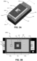
- FIGS. 3 A- 3 D show various views of an illustrative novel square-gate source-follower (SGSF) transistor 300 , according to various embodiments described herein.
- the SGSF transistor 300 can be an implementation of the source follower block 140 of FIG. 1 .
- FIG. 3 A a perspective view of the SGSF transistor 300 is shown.
- embodiments of the SGSF transistor 300 include an active layer 305 and a square-gate layer 320 .
- Embodiments can also include various insulation layers and related structures.
- Some implementations include inter-later structures 307 , such as silicon nitride spacers, insulating oxide layers, etc.
- Some implementations include shallow-trench isolation (STI) regions and/or other edge isolation structures 340 , such as to isolate between transistors and/or other components on the substrate of the pixel.
- STI shallow-trench isolation
- the active layer 305 can be implemented using a silicon substrate, such as a portion of a silicon wafer.
- the active layer 305 includes a drain-doped region 310 separated from a first source-doped region 315 a by a first current channel, and separated from a second source-doped region 315 b by a second current channel.
- Each of the drain-doped region 310 and the source-doped regions 315 are denoted by dashed circles intended to represent the approximate locations of the respective regions.
- each of the drain-doped region 310 and the source-doped regions 315 are n-doped regions (e.g., wells) in a p-doped substrate, such that application of a voltage proximate to the current channels causes current to flow in parallel from the drain-doped region 310 to the two source-doped regions 315 .
- each of the drain-doped region 310 and the source-doped regions 315 can be p-doped regions (e.g., wells) in an n-doped substrate, such that application of a voltage proximate to the current channels restricts current from flowing in the current channels between the drain-doped region 310 to the source-doped regions 315 .
- references to “parallel” current channels means that current from a single circuit node (e.g., the drain-doped region 310 ) splits along multiple current paths (e.g., to two separate source-doped regions 315 ) along independent paths, regardless of the geometric relationship between those paths.
- the current channels in the illustrated SGSF transistor 300 provide parallel current paths between the drain and source regions of the transistor, even though they are geometrically collinear (not geometrically parallel to each other).
- current channels is used herein to refer to a region through which current is intended to flow by design under particular operating conditions, even if current is not presently flowing in that region.
- references herein to the drain-doped region 310 being separated from source-doped regions 315 by current channels provides a clear description of the physical relationship between the drain-doped region 310 and the source-doped regions 315 , even when the device is not operating and/or no current is otherwise flowing.
- Embodiments of the square-gate layer 320 include at least two main-gate regions and at least one side-gate region.
- the embodiment of the SGSF transistor 300 illustrated in FIGS. 3 A- 3 D includes two main-gate regions and two side-gate regions, geometrically forming a square around the drain-doped region 310 .
- SGSF transistor 300 can have two main-gate regions coupled by a single side-gate region, such as geometrically forming a C-shape around three-fourths of the drain-doped region 310 .
- Features of the square-gate layer 320 are described with reference to all of FIGS. 3 A- 3 D for added clarity.
- FIG. 3 B shows a top view of the SGSF transistor 300 of FIG. 3 A .
- embodiments of the square-gate layer 320 can generally include main-gate regions 322 and side-gate regions 324 , geometrically forming a square around the drain-doped region 310 .
- the entire square-gate layer 320 can be formed as a single deposed structure, such as a polysilicon structure formed on the substrate 305 by any suitable foundry or other process.
- the drain-doped region 310 has a drain contact 312 electrically coupled with and disposed thereon
- each of the source-doped regions 315 has a respective source contact 317 electrically coupled with and disposed thereon
- the square-gate layer 320 has a gate contact 326 electrically coupled with and disposed thereon.
- the side-gate regions 324 electrically couple together the main-gate regions 322 .
- a single gate contact 326 can be used to control voltage to the entire square-gate layer 320 (i.e., at least to both main-gate regions 322 ).
- FIG. 3 C shows a length-wise cut view of the SGSF transistor 300 of FIG. 3 A , cut in accordance with cut line 350 a of FIG. 3 A .
- each main-gate region 322 of the square-gate layer 320 is disposed above a respective current channel to a respective side of the drain-doped region 310 opposite each other.
- the first main-gate region 322 a is disposed above the first current channel 325 a (between the drain-doped region 310 and the first source-doped region 315 a )
- the second main-gate region 322 b is disposed above the second current channel 325 b (between the drain-doped region 310 and the second source-doped region 315 b ).
- Arrows 327 show an example direction for current flow through the respective current channels 325 , indicating that flow of the drain current effectively splits along the two current channels 325 to flow in different directions.
- Each current channel 325 has an associated channel length (L) 330 .
- the current channels 325 are designed to be matched, such as by being equivalent in channel length 330 , doping, etc., such that current will split equally between the channels.
- Such design-intended parameter values are referred to herein as “nominal” values.
- some embodiments of the SGSF transistor 300 are designed to have nominally identical current channels, such as with the same nominal channel length 330 . However, it may be impractical or impossible (e.g., due to process variations and tolerances, material non-homogeneity, etc.) to manufacture the SGSF transistor 300 with identical current channels 325 .
- FIG. 3 D shows a width-wise cut view of the SGSF transistor 300 of FIG. 3 A , cut in accordance with cut line 350 b of FIG. 3 A . While only the first main-gate region 322 a can be seen in the cut view, a similar width-wise cut through the second main-gate region 322 b would look substantially the same (e.g., though implementations can have only one gate contact 326 on only one of the main-gate regions 322 ). As illustrated, at least because of doping parameters and the edge isolation structures 340 , the active region of the active layer 305 (i.e., the source-doped region 315 a in FIG. 3 D ) has a definable width (W) 335 .
- W definable width
- the width 335 is determined, at least in part, by pixel design parameters and manufacturing process constraints.
- the pixel footprint design balances allocated space between the photo-sensor block 110 and supporting components, including the source follower block 140 (which can be implemented by the SGSF transistor 300 ).
- the allocated space can typically define the maximum (or nominal) width of transistor components.
- the width 335 of the SGSF transistor 300 and the current channel length 330 of each current channel 325 can be similar to that of a conventional planar source-follower transistor used in conventional CIS photo-sensor blocks.
- the channel length 330 is at least half the width 335 , such that the overall physical length of the SGSF transistor 300 is greater than its overall width.
- L is greater than or equal to sixty percent of W.
- the SGSF transistor 300 architecture provides two parallel current channels 325 of length (L) 330 within the same width (W) 335 . Such an architecture manifests operationally as the SGSF transistor 300 having an apparent width of approximately 2W.
- the apparent width of the active region is approximately twice the physical width consumed by the SGSF transistor 300 in the pixel footprint. It can be demonstrated that transconductance of source-follower transistors is proportional to a ratio of W to L (i.e., to W divided by L). As such, doubling W with the same L can nominally double the transconductance of the transistor.
- a transconductance relationship for a source-follower transistor can be described as follows:
- g_m is the transconductance
- W is the active region width (or apparent width as in the SGSF transistor 300 )
- L is the current channel length (L_g is the gate length, which corresponds to L)
- I_D is the drain current (i.e., essentially the output of the transistor).
- C_ox oxygen capacitance
- ⁇ _eff effective gain
- m body coefficient
- g_ox oxide thickness
- gm 2 is linearly proportional to the term (W/L_g*g_ox) with constant current. Due at least to such a relationship, transconductance tends to contribute to a maximum frame rate supported by the pixel in the CIS. As such, increasing the W/L ratio by building CIS pixels with SGSF transistors 300 can tend to support higher frame rates of image acquisition.
- Another such feature relates to power consumption.
- the above relationship demonstrates that gm 2 is linearly proportional to the product of the drain current and the W/L ratio. As such, by increasing the W/L ratio, the same transconductance can be achieved with lower current, and thereby with lower power consumption. For example, if W/L is doubled in the above relationship (i.e., to 2W/L), the same gm 2 can be achieved with half the drain current.
- Another such feature relates to noise performance. It can be shown that within particular manufacturing parameters (e.g., C_ox), the drain current correlates to the surface carrier density (Ne), such that:
- transconductance is linearly proportional to the surface carrier density. Deeper channel implanting in the source-follower transistor can reduce surface carrier density and associated noise, but tends also to decrease transconductance. Thus, channel implant depth typically represents a trade-off between transconductance-related performance (e.g., efficiency) and noise-related performance. However, by increasing the W/L ratio, the same transconductance can be achieved with smaller surface carrier density (e.g., with deeper channel implanting), and thereby with less associated noise. For example, if W/L is doubled in the above relationship (i.e., to 2W/L), the same gm can be achieved with half the surface carrier density.
- the SGSF transistor 300 include additional features relating to noise performance.
- the square-gate layer 320 overlaps with the edge isolation structures 340 along at least one or both length-wise edges of the SGSF transistor 300 .
- two overlap regions 345 are illustrated.
- Edge isolation structures 340 such as STI regions, tend to have high electric field strengths (“E-fields”) and tend to trap electrons, which can produce relatively high amounts of noise.
- E-fields electric field strengths
- the gate length is effectively longer. This tends to suppress current flow along the length-wise edges of the SGSF transistor 300 , thereby reducing the noise conventionally produced in those regions.
- FIGS. 4 and 5 further illustrate the effects of desired current flow through current channels 325 and incidental current flow in other regions, according to various embodiments.
- FIG. 4 shows a simplified top view of an illustrative SGSF transistor 400 with two side-gate regions 324 , similar to the SGSF transistor 300 of FIG. 3 .
- the SGSF transistor 400 includes a square-gate layer 320 with first and second main-gate regions 322 and first and second side-gate regions 324 , forming a square around four sides of a drain-doped region 310 .
- the drain-doped region 310 is separated from each of two source-doped regions 315 by respective current channels 325 .
- Thick arrows show an example direction of parallel current flow through the channels from the drain-doped region 310 to each source-doped region 315 .
- FIG. 5 shows a simplified top view of an illustrative SGSF transistor 500 with only a single side-gate region 324 .
- the square-gate layer 320 includes first and second main-gate regions 322 coupled together by a single side-gate region 324 , forming a partial square (e.g., a C-shape) around three of four sides of the drain-doped region 310 .
- the drain-doped region 310 is separated from each of two source-doped regions 315 by respective current channels 325 , and thick arrows show an example direction of parallel current flow through the channels from the drain-doped region 310 to each source-doped region 315 .
- thick arrows show an example direction of parallel current flow through the channels from the drain-doped region 310 to each source-doped region 315 .
- incidental current flow occurs along the edges due at least in part to the E-fields of the edge isolation structures 340 .
- incidental current flow may be similar to that of FIG. 4 , as indicated by arrows 410 .
- presence of the single side-gate region 324 can reduce the overall amount of noise generated by the edge isolation structures 340 .
- FIG. 6 shows a simplified physical layout of an illustrative CIS pixel 600 having an integrated SGSF transistor 300 , according to various embodiments.
- a center region of the illustrated layout includes a photo-sensor block 110 with four photodiodes 115 .
- An upper portion of the illustrated layout includes a gain block 120 and a reset block 130 , with corresponding contacts.
- a lower portion of the illustrated layout includes a select block 150 and the novel source follower block 140 , implemented as SGSF transistor 300 . It can be seen that the width of the various component blocks is established by the design of the layout, and that embodiments of the SGSF transistor 300 can be implemented within such a layout by consuming otherwise unused area in the length dimension (i.e., horizontal with reference to the illustrated layout).
- the SGSF transistor 300 can be fit within conventional spacing parameters, including placing the drain contact 312 , source contacts 317 , and gate contact 326 in locations that can conform to conventional manufacturing processes for the CIS pixel (e.g., within typical physical design parameters of a standard 2-by-2 CIS pixel layout).
- FIG. 7 shows a simplified pixel schematic 700 for an illustrative CIS pixel having an integrated SGSF transistor 300 , according to various embodiments.
- the schematic can represent the CIS pixel 600 shown in FIG. 6 .
- the schematic includes a photo-sensor block 110 with four photodiodes 115 , a gain block 120 , a reset block 130 , a select block 150 , and a SGSF transistor 300 (as an implementation of a source follower block 140 ).
- the select block 150 is coupled between the SGSF transistor 300 and a bus 160 .
- the bus 160 is a column select bus with a bias current 710 .
- the schematic of the SGSF transistor 300 is shown with schematic representations of the drain contact 312 , the source contact 317 , and the gate contact 326 . It can be seen in the SGSF transistor 300 can effectively be modeled as two field-effect transistors (FETs) coupled active layer 305 at shared drain node (i.e., the physical implementation can include only a single drain-doped region 310 , as described herein), and with their gates coupled together (i.e., the physical implementation includes the square-gate layer 320 , which effectively manifests as two main-gate regions 322 coupled together via the one or more side-gate regions 324 ). The schematic shows only a single source contact 317 .
- FETs field-effect transistors
- the physical design may include two separate source-doped regions 315 , each with a corresponding source contact 317 , and the multiple source contacts 317 may be coupled together when implemented in the circuit.
- the SGSF transistor 300 can be designed with the source-doped regions 315 coupled together, so that only a single source contact 317 is provided.
- the common drain node (coupled with drain contact 312 ) is coupled with a voltage reference (Vdd).
- Vdd voltage reference
- Applying a gate voltage at gate contact 326 actuates the gates of both represented FETs, causing current to flow in parallel from the common drain node to the respective source nodes of both FETs (coupled together at source contact 317 ).
- a first element, component, discussed below could be termed a second element, component, without departing from the teachings of the present invention.
- the terms “logic low,” “low state,” “low level,” “logic low level,” “low,” or “0” are used interchangeably.
- the terms “logic high,” “high state,” “high level,” “logic high level,” “high,” or “1” are used interchangeably.
- the terms “a”, “an” and “the” may include singular and plural references. It will be further understood that the terms “comprising”, “including”, having” and variants thereof, when used in this specification, specify the presence of stated features, steps, operations, elements, and/or components, but do not preclude the presence or addition of one or more other features, steps, operations, elements, components, and/or groups thereof. In contrast, the term “consisting of” when used in this specification, specifies the stated features, steps, operations, elements, and/or components, and precludes additional features, steps, operations, elements and/or components. Furthermore, as used herein, the words “and/or” may refer to and encompass any possible combinations of one or more of the associated listed items.
Landscapes
- Engineering & Computer Science (AREA)
- Multimedia (AREA)
- Signal Processing (AREA)
- Solid State Image Pick-Up Elements (AREA)
Abstract
Description
g m =WC ox V sat
where W is the width of the source-follower transistor (e.g.,
where M is an empirical parameter, and β is a frequency-related parameter. The voltage signal at the source-follower transistor gate tends to be proportional to the gate capacitance, described by C_ox*W*L, where L is the current channel length (e.g.,
As noted above, g_m is the transconductance, W is the active region width (or apparent width as in the SGSF transistor 300), L is the current channel length (L_g is the gate length, which corresponds to L), and I_D is the drain current (i.e., essentially the output of the transistor). Other parameters, such as C_ox (oxide capacitance), μ_eff (effective gain), m (body coefficient), and g_ox (oxide thickness) tend to be relatively constant and dependent on the manufacturing process and other such characteristics. It can be seen from this relationship that transconductance has a proportional relationship to the ratio of W to L for the source-follower transistor (i.e., whether the traditional planar source-follower transistor, or the novel SGSF transistor 300). Thus, increasing W relative to L (e.g., nominally doubling W) provides a number of features.
As such, transconductance is linearly proportional to the surface carrier density. Deeper channel implanting in the source-follower transistor can reduce surface carrier density and associated noise, but tends also to decrease transconductance. Thus, channel implant depth typically represents a trade-off between transconductance-related performance (e.g., efficiency) and noise-related performance. However, by increasing the W/L ratio, the same transconductance can be achieved with smaller surface carrier density (e.g., with deeper channel implanting), and thereby with less associated noise. For example, if W/L is doubled in the above relationship (i.e., to 2W/L), the same gm can be achieved with half the surface carrier density.
Claims (12)
0.6W≤L≤W.
Priority Applications (2)
| Application Number | Priority Date | Filing Date | Title |
|---|---|---|---|
| US17/141,141 US11830897B2 (en) | 2021-01-04 | 2021-01-04 | Square-gate source-follower for CMOS image sensor pixel |
| CN202111596648.6A CN114725139A (en) | 2021-01-04 | 2021-12-24 | Square gate source follower for CMOS image sensor pixels |
Applications Claiming Priority (1)
| Application Number | Priority Date | Filing Date | Title |
|---|---|---|---|
| US17/141,141 US11830897B2 (en) | 2021-01-04 | 2021-01-04 | Square-gate source-follower for CMOS image sensor pixel |
Publications (2)
| Publication Number | Publication Date |
|---|---|
| US20220216252A1 US20220216252A1 (en) | 2022-07-07 |
| US11830897B2 true US11830897B2 (en) | 2023-11-28 |
Family
ID=82218871
Family Applications (1)
| Application Number | Title | Priority Date | Filing Date |
|---|---|---|---|
| US17/141,141 Active 2042-01-30 US11830897B2 (en) | 2021-01-04 | 2021-01-04 | Square-gate source-follower for CMOS image sensor pixel |
Country Status (2)
| Country | Link |
|---|---|
| US (1) | US11830897B2 (en) |
| CN (1) | CN114725139A (en) |
Families Citing this family (2)
| Publication number | Priority date | Publication date | Assignee | Title |
|---|---|---|---|---|
| US20230013187A1 (en) * | 2021-07-14 | 2023-01-19 | Shenzhen GOODIX Technology Co., Ltd. | Split-sel cmos image sensor pixel |
| CN119230574B (en) * | 2024-09-24 | 2025-10-24 | 长鑫科技集团股份有限公司 | Image sensor and method for forming the same |
Citations (1)
| Publication number | Priority date | Publication date | Assignee | Title |
|---|---|---|---|---|
| US20110049590A1 (en) * | 2009-08-28 | 2011-03-03 | Sony Corporation | Solid-state imaging device, manufacturing method thereof, and electronic apparatus |
Family Cites Families (4)
| Publication number | Priority date | Publication date | Assignee | Title |
|---|---|---|---|---|
| JP2011114036A (en) * | 2009-11-24 | 2011-06-09 | Brookman Technology Inc | Insulated gate type semiconductor element and insulated gate type semiconductor integrated circuit |
| US20130256509A1 (en) * | 2012-03-27 | 2013-10-03 | Omnivision Technologies, Inc. | Dual source follower pixel cell architecture |
| JP6279332B2 (en) * | 2014-01-21 | 2018-02-14 | ルネサスエレクトロニクス株式会社 | Semiconductor device |
| KR102560699B1 (en) * | 2017-10-30 | 2023-07-27 | 삼성전자주식회사 | Image Sensor |
-
2021
- 2021-01-04 US US17/141,141 patent/US11830897B2/en active Active
- 2021-12-24 CN CN202111596648.6A patent/CN114725139A/en active Pending
Patent Citations (1)
| Publication number | Priority date | Publication date | Assignee | Title |
|---|---|---|---|---|
| US20110049590A1 (en) * | 2009-08-28 | 2011-03-03 | Sony Corporation | Solid-state imaging device, manufacturing method thereof, and electronic apparatus |
Also Published As
| Publication number | Publication date |
|---|---|
| CN114725139A (en) | 2022-07-08 |
| US20220216252A1 (en) | 2022-07-07 |
Similar Documents
| Publication | Publication Date | Title |
|---|---|---|
| US20060108613A1 (en) | CMOS image sensor | |
| KR100461975B1 (en) | Method for forming trench isolation layer in image sensor | |
| US7227208B2 (en) | Solid-state image pickup apparatus | |
| JP4444596B2 (en) | Method for manufacturing hybrid element isolation structure of image sensor | |
| JP5539104B2 (en) | Photoelectric conversion device and imaging system using the same | |
| US11189655B1 (en) | Isolation structure for suppressing floating diffusion junction leakage in CMOS image sensor | |
| JPH09246514A (en) | Amplification type solid-state imaging device | |
| US8476102B2 (en) | Solid state image pickup device and method for manufacturing solid state image pickup device | |
| US8592874B2 (en) | Solid state imaging device | |
| US7880206B2 (en) | CMOS image sensor with asymmetric well structure of source follower | |
| KR100880528B1 (en) | CMOS image sensor | |
| US11830897B2 (en) | Square-gate source-follower for CMOS image sensor pixel | |
| KR101534544B1 (en) | Image sensor with pixel cell with epilayer, system comprising same, and pixel cell forming method | |
| US8039916B2 (en) | CMOS pixel sensor with depleted photocollectors and a depleted common node | |
| US6351002B1 (en) | Photodiode | |
| US12142620B2 (en) | Complementary metal-oxide semiconductor (CMOS) image sensors with saddle-gate source follower for imaging pixels | |
| KR100261349B1 (en) | Active type solid-state imaging device and method for fabricating the same | |
| KR20050039167A (en) | Cmos image sensor and method for fabricating the same | |
| US12148774B2 (en) | Trench-gate source follower for low-noise scaled pixel | |
| US20230013187A1 (en) | Split-sel cmos image sensor pixel | |
| US20070102739A1 (en) | Cmos image sensor | |
| US20070004076A1 (en) | CMOS image sensor including two types of device isolation regions and method of fabricating the same | |
| KR100766497B1 (en) | Image sensor | |
| KR100444490B1 (en) | Image sensor for protecting the Reference broading effect | |
| KR100451591B1 (en) | Pixel of a cmos image sensor |
Legal Events
| Date | Code | Title | Description |
|---|---|---|---|
| AS | Assignment |
Owner name: GOODIX TECHNOLOGY INC., CALIFORNIA Free format text: ASSIGNMENT OF ASSIGNORS INTEREST;ASSIGNORS:GAO, YUNFEI;OH, TAE SEOK;XIAO, JINWEN;SIGNING DATES FROM 20201222 TO 20210104;REEL/FRAME:054805/0122 |
|
| FEPP | Fee payment procedure |
Free format text: ENTITY STATUS SET TO UNDISCOUNTED (ORIGINAL EVENT CODE: BIG.); ENTITY STATUS OF PATENT OWNER: LARGE ENTITY |
|
| AS | Assignment |
Owner name: SHENZHEN GOODIX TECHNOLOGY CO., LTD., CHINA Free format text: ASSIGNMENT OF ASSIGNORS INTEREST;ASSIGNOR:GOODIX TECHNOLOGY INC.;REEL/FRAME:056554/0553 Effective date: 20210614 |
|
| STPP | Information on status: patent application and granting procedure in general |
Free format text: DOCKETED NEW CASE - READY FOR EXAMINATION |
|
| STPP | Information on status: patent application and granting procedure in general |
Free format text: NON FINAL ACTION MAILED |
|
| STPP | Information on status: patent application and granting procedure in general |
Free format text: RESPONSE TO NON-FINAL OFFICE ACTION ENTERED AND FORWARDED TO EXAMINER |
|
| STPP | Information on status: patent application and granting procedure in general |
Free format text: NOTICE OF ALLOWANCE MAILED -- APPLICATION RECEIVED IN OFFICE OF PUBLICATIONS |
|
| STPP | Information on status: patent application and granting procedure in general |
Free format text: PUBLICATIONS -- ISSUE FEE PAYMENT VERIFIED |
|
| STCF | Information on status: patent grant |
Free format text: PATENTED CASE |