US11829896B2 - Uncertainty-based data filtering in a vehicle - Google Patents
Uncertainty-based data filtering in a vehicle Download PDFInfo
- Publication number
- US11829896B2 US11829896B2 US16/926,721 US202016926721A US11829896B2 US 11829896 B2 US11829896 B2 US 11829896B2 US 202016926721 A US202016926721 A US 202016926721A US 11829896 B2 US11829896 B2 US 11829896B2
- Authority
- US
- United States
- Prior art keywords
- machine learning
- learning model
- result
- sensor data
- independent
- Prior art date
- Legal status (The legal status is an assumption and is not a legal conclusion. Google has not performed a legal analysis and makes no representation as to the accuracy of the status listed.)
- Active, expires
Links
- 238000001914 filtration Methods 0.000 title claims abstract description 35
- 238000010801 machine learning Methods 0.000 claims abstract description 184
- 238000000034 method Methods 0.000 claims description 92
- 238000004590 computer program Methods 0.000 claims description 9
- 238000012545 processing Methods 0.000 description 91
- 230000008569 process Effects 0.000 description 60
- 230000009471 action Effects 0.000 description 44
- 239000004744 fabric Substances 0.000 description 36
- 238000004891 communication Methods 0.000 description 22
- 230000008859 change Effects 0.000 description 21
- 230000006870 function Effects 0.000 description 21
- 238000013480 data collection Methods 0.000 description 14
- 238000010586 diagram Methods 0.000 description 14
- 230000005540 biological transmission Effects 0.000 description 11
- 238000001514 detection method Methods 0.000 description 9
- 230000037361 pathway Effects 0.000 description 9
- 238000013500 data storage Methods 0.000 description 8
- 230000001133 acceleration Effects 0.000 description 5
- 238000013473 artificial intelligence Methods 0.000 description 5
- 230000007613 environmental effect Effects 0.000 description 5
- 230000003287 optical effect Effects 0.000 description 5
- 230000002730 additional effect Effects 0.000 description 4
- 230000004913 activation Effects 0.000 description 3
- 238000003491 array Methods 0.000 description 3
- 230000008901 benefit Effects 0.000 description 3
- 230000009849 deactivation Effects 0.000 description 3
- 238000013459 approach Methods 0.000 description 2
- 230000006835 compression Effects 0.000 description 2
- 238000007906 compression Methods 0.000 description 2
- 230000007246 mechanism Effects 0.000 description 2
- 238000005192 partition Methods 0.000 description 2
- 230000001902 propagating effect Effects 0.000 description 2
- 230000004044 response Effects 0.000 description 2
- RYGMFSIKBFXOCR-UHFFFAOYSA-N Copper Chemical compound [Cu] RYGMFSIKBFXOCR-UHFFFAOYSA-N 0.000 description 1
- 238000004458 analytical method Methods 0.000 description 1
- 238000013528 artificial neural network Methods 0.000 description 1
- 230000006399 behavior Effects 0.000 description 1
- 230000010267 cellular communication Effects 0.000 description 1
- 229910052802 copper Inorganic materials 0.000 description 1
- 239000010949 copper Substances 0.000 description 1
- 238000012517 data analytics Methods 0.000 description 1
- 238000013135 deep learning Methods 0.000 description 1
- 230000001419 dependent effect Effects 0.000 description 1
- 238000000605 extraction Methods 0.000 description 1
- 239000000835 fiber Substances 0.000 description 1
- 238000009434 installation Methods 0.000 description 1
- 230000004807 localization Effects 0.000 description 1
- 238000012423 maintenance Methods 0.000 description 1
- 238000007726 management method Methods 0.000 description 1
- 238000004519 manufacturing process Methods 0.000 description 1
- 238000013507 mapping Methods 0.000 description 1
- 238000012986 modification Methods 0.000 description 1
- 230000004048 modification Effects 0.000 description 1
- 230000002093 peripheral effect Effects 0.000 description 1
- 230000002265 prevention Effects 0.000 description 1
- 239000004065 semiconductor Substances 0.000 description 1
- 230000003068 static effect Effects 0.000 description 1
- 238000012546 transfer Methods 0.000 description 1
- 238000013519 translation Methods 0.000 description 1
- 230000000007 visual effect Effects 0.000 description 1
Images


Classifications
-
- G—PHYSICS
- G06—COMPUTING; CALCULATING OR COUNTING
- G06N—COMPUTING ARRANGEMENTS BASED ON SPECIFIC COMPUTATIONAL MODELS
- G06N5/00—Computing arrangements using knowledge-based models
- G06N5/04—Inference or reasoning models
- G06N5/048—Fuzzy inferencing
-
- G—PHYSICS
- G05—CONTROLLING; REGULATING
- G05D—SYSTEMS FOR CONTROLLING OR REGULATING NON-ELECTRIC VARIABLES
- G05D1/00—Control of position, course or altitude of land, water, air, or space vehicles, e.g. automatic pilot
- G05D1/0088—Control of position, course or altitude of land, water, air, or space vehicles, e.g. automatic pilot characterized by the autonomous decision making process, e.g. artificial intelligence, predefined behaviours
-
- G—PHYSICS
- G06—COMPUTING; CALCULATING OR COUNTING
- G06N—COMPUTING ARRANGEMENTS BASED ON SPECIFIC COMPUTATIONAL MODELS
- G06N20/00—Machine learning
-
- G—PHYSICS
- G05—CONTROLLING; REGULATING
- G05D—SYSTEMS FOR CONTROLLING OR REGULATING NON-ELECTRIC VARIABLES
- G05D2201/00—Application
- G05D2201/02—Control of position of land vehicles
- G05D2201/0213—Road vehicle, e.g. car or truck
Definitions
- the field of the invention is data processing, or, more specifically, methods, apparatus, autonomous vehicles, and products for uncertainty-based data filtering in a vehicle.
- Sensor-equipped vehicles such as autonomous vehicles, may record a large amount of sensor data during operation. As the data size grows, the resources required to store and process the recorded sensor data increases. Moreover, the recorded data may include large amounts of data that provide little to no value in their subsequent analysis.
- Uncertainty-based data filtering in a vehicle may include acquiring sensor data from a plurality of sensors of the autonomous vehicle; applying a first machine learning model to the sensor data; determining that a result of the first machine learning model agrees with another result; and transmitting, based on the result of the first machine learning model disagreeing with the other result, the sensor data to a server.
- FIG. 1 shows example views of an autonomous vehicle for uncertainty-based data filtering in a vehicle.
- FIG. 2 is block diagram of an autonomous computing system for uncertainty-based data filtering in a vehicle.
- FIG. 3 is a block diagram of a redundant power fabric for uncertainty-based data filtering in a vehicle.
- FIG. 4 is a block diagram of a redundant data fabric for uncertainty-based data filtering in a vehicle.
- FIG. 5 is an example view of process allocation across CPU packages for uncertainty-based data filtering in a vehicle.
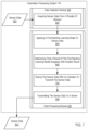
- FIG. 6 is a flowchart of an example method for uncertainty-based data filtering in a vehicle.
- FIG. 7 is a flowchart of an example method for uncertainty-based data filtering in a vehicle.
- FIG. 8 is a flowchart of an example method for uncertainty-based data filtering in a vehicle.
- FIG. 9 is a flowchart of an example method for uncertainty-based data filtering in a vehicle.
- FIG. 1 shows multiple views of an autonomous vehicle 100 configured for uncertainty-based data filtering in a vehicle according to embodiments of the present invention.
- Right side view 101 a shows a right side of the autonomous vehicle 100 .
- Shown in the right side view 101 a are cameras 102 and 103 , configured to capture image data, video data, and/or audio data of the environmental state of the autonomous vehicle 100 from the perspective of the right side of the car.
- Front view 101 b shows a front side of the autonomous vehicle 100 .
- Shown in the front view 101 b are cameras 104 and 106 , configured to capture image data, video data, and/or audio data of the environmental state of the autonomous vehicle 100 from the perspective of the front of the car.
- Rear view 101 c shows a rear side of the autonomous vehicle 100 .
- Shown in the rear view 101 c are cameras 108 and 110 , configured to capture image data, video data, and/or audio data of the environmental state of the autonomous vehicle 100 from the perspective of the rear of the car.
- Top view 101 d shows a rear side of the autonomous vehicle 100 . Shown in the top view 101 d are cameras 102 - 110 . Also shown are cameras 112 and 114 , configured to capture image data, video data, and/or audio data of the environmental state of the autonomous vehicle 100 from the perspective of the left side of the car.
- the automation computing system 116 comprises one or more computing devices configured to control one or more autonomous operations (e.g., autonomous driving operations) of the autonomous vehicle 100 .
- the automation computing system 116 may be configured to process sensor data (e.g., data from the cameras 102 - 114 and potentially other sensors), operational data (e.g., a speed, acceleration, gear, orientation, turning direction), and other data to determine a operational state and/or operational history of the autonomous vehicle.
- the automation computing system 116 may then determine one or more operational commands for the autonomous vehicle (e.g., a change in speed or acceleration, a change in brake application, a change in gear, a change in turning or orientation, etc.).
- the automation computing system 116 may also capture and store sensor data. Operational data of the autonomous vehicle may also be stored in association with corresponding sensor data, thereby indicating the operational data of the autonomous vehicle 100 at the time the sensor data was captured.
- autonomous vehicle 100 if FIG. 1 is shown as car, it is understood that autonomous vehicles 100 configured for uncertainty-based data filtering in a vehicle may also include other vehicles, including motorcycles, planes, helicopters, unmanned aerial vehicles (UAVs, e.g., drones), or other vehicles as can be appreciated. Moreover, it is understood that additional cameras or other external sensors may also be included in the autonomous vehicle 100 .
- UAVs unmanned aerial vehicles
- FIG. 2 sets forth a block diagram of automated computing machinery comprising an exemplary automation computing system 116 configured for uncertainty-based data filtering in a vehicle according to embodiments of the present invention.
- the automation computing system 116 of FIG. 2 includes at least one computer Central Processing Unit (CPU) package 204 as well as random access memory 206 (RAM′) which is connected through a high speed memory bus 208 and bus adapter 210 to CPU packages 204 via a front side bus 211 and to other components of the automation computing system 116 .
- CPU Central Processing Unit
- RAM′ random access memory
- a CPU package 204 may comprise a plurality of processing units.
- each CPU package 204 may comprise a logical or physical grouping of a plurality of processing units.
- Each processing unit may be allocated a particular process for execution.
- each CPU package 204 may comprise one or more redundant processing units.
- a redundant processing unit is a processing unit not allocated a particular process for execution unless a failure occurs in another processing unit. For example, when a given processing unit allocated a particular process fails, a redundant processing unit may be selected and allocated the given process.
- a process may be allocated to a plurality of processing units within the same CPU package 204 or different CPU packages 204 . For example, a given process may be allocated to a primary processing unit in a CPU package 204 .
- the results or output of the given process may be output from the primary processing unit to a receiving process or service.
- the given process may also be executed in parallel on a secondary processing unit.
- the secondary processing unit may be included within the same CPU package 204 or a different CPU package 204 .
- the secondary processing unit may not provide its output or results of the process until the primary processing unit fails.
- the receiving process or service will then receive data from the secondary processing unit.
- a redundant processing unit may then be selected and have allocated the given process to ensure that two or more processing units are allocated the given process for redundancy and increased reliability.
- the CPU packages 204 are communicatively coupled to one or more sensors 212 .
- the sensors 212 are configured to capture sensor data describing the operational and environmental conditions of an autonomous vehicle.
- the sensors 212 may include cameras (e.g., the cameras 102 - 114 of FIG. 1 ), accelerometers, Global Positioning System (GPS) radios, Lidar sensors, or other sensors as can be appreciated.
- GPS Global Positioning System
- the sensors 212 are shown as being external to the automation computing system 116 , it is understood that one or more of the sensors 212 may reside as a component of the automation computing system 212 (e.g., on the same board, within the same housing or chassis).
- the sensors 212 may be communicatively coupled with the CPU packages 204 via a switched fabric 213 .
- the switched fabric 213 comprises a communications topology through which the CPU packages 204 and sensors 212 are coupled via a plurality of switching mechanisms (e.g., latches, switches, crossbar switches, field programmable gate arrays (FPGAs), etc.).
- the switched fabric 213 may implement a mesh connection connecting the CPU packages 204 and sensors 212 as endpoints, with the switching mechanisms serving as intermediary nodes of the mesh connection.
- the CPU packages 204 and sensors 212 may be in communication via a plurality of switched fabrics 213 .
- each of the switched fabrics 213 may include the CPU packages 204 and sensors 212 , or a subset of the CPU packages 204 and sensors 212 , as endpoints.
- Each switched fabric 213 may also comprise a respective plurality of switching components.
- the switching components of a given switched fabric 213 may be independent (e.g., not connected) of the switching components of other switched fabrics 213 such that only switched fabric 213 endpoints (e.g., the CPU packages 204 and sensors 212 ) are overlapping across the switched fabrics 213 .
- This provides redundancy such that, should a connection between a CPU package 204 and sensor 212 fail in one switched fabric 213 , the CPU package 204 and sensor 212 may remain connected via another switched fabric 213 .
- a communications path excluding the failed component and including a functional redundant component may be established.
- the CPU packages 204 and sensors 212 are configured to receive power from one or more power supplies 215 .
- the power supplies 215 may comprise an extension of a power system of the autonomous vehicle 100 or an independent power source (e.g., a battery).
- the power supplies 215 may supply power to the CPU packages 204 and sensors 212 by another switched fabric 214 .
- the switched fabric 214 provides redundant power pathways such that, in the event of a failure in a power connection, a new power connection pathway may be established to the CPU packages 204 and sensors 214 .
- the automation module 220 may be configured to process sensor data from the sensors 212 to determine one or more operational commands for an autonomous vehicle 100 to affect the movement, direction, or other function of the autonomous vehicle 100 , thereby facilitating autonomous driving or operation of the vehicle.
- Such operational commands may include a change in the speed of the autonomous vehicle 100 , a change in steering direction, a change in gear, or other command as can be appreciated.
- the automation module 220 may provide sensor data and/or processed sensor data as one or more inputs to a trained machine learning model (e.g., a trained neural network) to determine the one or more operational commands.
- the operational commands may then be communicated to autonomous vehicle control systems 223 via a vehicle interface 222 .
- the autonomous vehicle control systems 223 are configured to affect the movement and operation of the autonomous vehicle 100 .
- the autonomous vehicle control systems 223 may turn or otherwise change the direction of the autonomous vehicle 100 , accelerate or decelerate the autonomous vehicle 100 , change a gear of the autonomous vehicle 100 , or otherwise affect the movement and operation of the autonomous vehicle 100 .
- a data collection module 224 configured to process and/or store sensor data received from the one or more sensors 212 .
- the data collection module 224 may store the sensor data as captured by the one or more sensors 212 , or processed sensor data 212 (e.g., sensor data 212 having object recognition, compression, depth filtering, or other processes applied). Such processing may be performed by the data collection module 224 in real-time or in substantially real-time as the sensor data is captured by the one or more sensors 212 .
- the processed sensor data may then be used by other functions or modules.
- the automation module 220 may use processed sensor data as input to determine one or more operational commands.
- the data collection module 224 may store the sensor data in data storage 218 .
- the data processing module 226 is configured to perform one or more processes on stored sensor data (e.g., stored in data storage 218 by the data collection module 218 ) prior to upload to a server 227 . Such operations can include filtering, compression, encoding, decoding, or other operations as can be appreciated. The data processing module 226 may then communicate the processed and stored sensor data to the server 227 .
- the data collection module 224 may acquire sensor data from the plurality of sensors 212 of the autonomous vehicle 100 .
- the sensor data may include image, audio, and/or video data from camera sensors 212 , GPS data from a GPS radio sensor 212 , acceleration data from an accelerometer sensor 212 , or other sensor as can be appreciated.
- the sensor data from a particular sensor 212 may comprise contextual metadata describing a time, location, or other information associated with a context in which the sensor data was captured.
- the contextual metadata for a particular sensor 212 may be based at least in part on sensor data from another sensor 212 .
- sensor data from a camera sensor 212 may comprise location metadata based on sensor data from the GPS sensor 212 , as well as potentially other contextual metadata.
- Acquiring the sensor data from the plurality of sensors 212 may include acquiring or receiving the sensor data from a buffer or memory of the particular sensor 212 or acquiring the sensor data from a bus or communications pathway connected to the sensors 212 .
- Acquiring the sensor data may comprise storing the sensor data in data storage 218 and/or in volatile memory.
- the data processing module 226 may apply a first machine learning model to the sensor data.
- the data processing module 226 may provide the sensor data as input to the first machine learning model.
- the result (e.g., the output) of the first machine learning model may be associated with a classification of a portion of the sensor data (e.g., a detected object or event, an identification of a detected object or event, etc.).
- a result may comprise one or more discrete or binary detection (e.g., an indication that an object was detected), one or more labels of the detected objects or events (e.g., “stop sign,” “pedestrian”) or another discrete detection.
- Such a result may also comprise one or more confidence scores associated with one or more detectable or identifiable objects (e.g., a confidence that a particular object or event was detected).
- the result of the first machine learning model may also be associated with a driver action (e.g., an action performable by a driver to affect one or more functions or devices of a vehicle).
- a driver action e.g., an action performable by a driver to affect one or more functions or devices of a vehicle.
- Such actions may include a change in velocity, a change in brake application, a change in gear, a change in direction or heading, an activation or deactivation of a device or function, or another action.
- the result may comprise a discrete or binary prediction as to whether or not a particular action will or will not be performed.
- the result may also comprise one or more confidence scores associated indicating a confidence that one or more actions may be performed.
- the data processing module 226 may then determine that the result of the first machine learning model agrees with another result.
- the other result may comprise a result of a second machine learning model applied to the sensor data. Accordingly, a disagreement between the result of the first machine learning model and the second machine learning model indicates that the second machine learning model provided a different classification, detection, or prediction than the first machine learning model.
- the other result may comprise one or more detected driver actions. Accordingly, a disagreement between the result of the first machine learning model and other result indicates that the driver performed one or more actions differing from those predicted by the first machine learning model (e.g., the driver performed a different action, the driver performed an additional action, the driver failed to perform an action).
- the first machine learning model and the second machine learning model will disagree based on providing, as results, different discrete results.
- the first machine learning model and the driver action will disagree where the driver performs one or more actions differing from those predicted by the first machine learning model (e.g., the driver performed a different action, the driver performed an additional action, the driver failed to perform an action).
- the first machine learning model and the second machine learning model will disagree based on a degree of divergence between the result of the first machine learning model and the second machine learning model, or the driver action.
- determining that the result of the first machine learning model disagrees with the other result may comprise determining that a certainty score based on the result of the first machine learning model and the other result meets a threshold.
- the certainty score may be based on a differential function (e.g., cosine differential, arithmetic differential) applied to the result of the first machine learning model and the other result.
- the certainty score reflects a degree to which the result of the first machine learning model is different from the other result (e.g., the result of the second machine learning model or the driver action).
- the data processing module 226 may then transmit, based on the result of the first machine learning model disagreeing with the other result, the sensor data to a server 227 .
- the data processing module 226 may cause immediate or near-immediate transmission of the sensor data using any available network connection or a first available network connection.
- the data processing module 226 may also store the sensor data (e.g., in data storage 218 ) with an indication to transmit the sensor data.
- the indication to transmit the sensor data may comprise a flag or tag indicating that the sensor data should be transmitted.
- the indication may also comprise a score or value associated with the sensor data and meeting a threshold. Thus, a process selecting data for transmission based on value would select the sensor data due to the score or value meeting the threshold.
- the data processing module 226 may then transmit the stored sensor data in response to one or more conditions being satisfied (e.g., a particular network connection is available, the vehicle enters a stationary or parked mode, an amount of used storage space meets a threshold, etc.).
- the data processing module may discard, delete, or refrain from storing the sensor data.
- the data processing module may discard, delete, or refrain from storing the sensor data.
- sensor data that caused a disagreement between the first machine learning model and the second machine learning model or the driver action will be selected for transmission to the server 227 .
- machine learning models e.g., new or revised machine learning models
- the first machine learning model and the second machine learning model may be received from a server 227 .
- the corresponding sensor data may then be added to a data corpus of the server 227 to determine why such a disagreement occurred and further refine the machine learning models.
- the hypervisor 228 is configured to manage the configuration and execution of one or more virtual machines 229 .
- each virtual machine 229 may emulate and/or simulate the operation of a computer.
- each virtual machine 229 may comprise a guest operating system 216 for the simulated computer.
- the hypervisor 228 may manage the creation of a virtual machine 229 including installation of the guest operating system 216 .
- the hypervisor 228 may also manage when execution of a virtual machine 229 begins, is suspended, is resumed, or is terminated.
- the hypervisor 228 may also control access to computational resources (e.g., processing resources, memory resources, device resources) by each of the virtual machines.
- Each of the virtual machines 229 may be configured to execute one or more of the automation module 220 , the data collection module 224 , the data processing module 226 , or combinations thereof. Moreover, as is set forth above, each of the virtual machines 229 may comprise its own guest operating system 216 .
- Guest operating systems 216 useful in autonomous vehicles in accordance with some embodiments of the present disclosure include UNIXTM, LinuxTM, Microsoft WindowsTM, AIXTM, IBM's iOSTM, and others as will occur to those of skill in the art.
- the autonomous vehicle 100 may be configured to execute a first operating system when the autonomous vehicle is in an autonomous (or even partially autonomous) driving mode and the autonomous vehicle 100 may be configured to execute a second operating system when the autonomous vehicle is not in an autonomous (or even partially autonomous) driving mode.
- the first operating system may be formally verified, secure, and operate in real-time such that data collected from the sensors 212 are processed within a predetermined period of time, and autonomous driving operations are performed within a predetermined period of time, such that data is processed and acted upon essentially in real-time.
- the second operating system may not be formally verified, may be less secure, and may not operate in real-time as the tasks that are carried out (which are described in greater detail below) by the second operating system are not as time-sensitive the tasks (e.g., carrying out self-driving operations) performed by the first operating system.
- the autonomous vehicle 100 may be configured to execute a first operating system when the autonomous vehicle is in an autonomous (or even partially autonomous) driving mode and the autonomous vehicle 100 may be configured to execute a second operating system when the autonomous vehicle is not in an autonomous (or even partially autonomous) driving mode
- one CPU or other appropriate entity such as a chip, CPU core, and so on
- a second CPU or other appropriate entity
- processing resources such as a CPU may be partitioned where a first partition supports the execution of the first operating system and a second partition supports the execution of the second operating system.
- the guest operating systems 216 may correspond to a particular operating system modality.
- An operating system modality is a set of parameters or constraints which a given operating system satisfies, and are not satisfied by operating systems of another modality.
- a given operating system may be considered a “real-time operating system” in that one or more processes executed by the operating system must be performed according to one or more time constraints.
- the automation module 220 must make determinations as to operational commands to facilitate autonomous operation of a vehicle. Accordingly, the automation module 220 must make such determinations within one or more time constraints in order for autonomous operation to be performed in real time.
- the automation module 220 may then be executed in an operating system (e.g., a guest operating system 216 of a virtual machine 229 ) corresponding to a “real-time operating system” modality.
- the data processing module 226 may be able to perform its processing of sensor data independent of any time constrains, and may then be executed in an operating system (e.g., a guest operating system 216 of a virtual machine 229 ) corresponding to a “non-real-time operating system” modality.
- an operating system may comprise a formally verified operating system.
- a formally verified operating system is an operating system for which the correctness of each function and operation has been verified with respect to a formal specification according to formal proofs.
- a formally verified operating system and an unverified operating system can be said to operate in different modalities.
- the automation module 220 , data collection module 224 , data collection module 224 , data processing module 226 , hypervisor 228 , and virtual machine 229 in the example of FIG. 2 are shown in RAM 206 , but many components of such software typically are stored in non-volatile memory also, such as, for example, on data storage 218 , such as a disk drive. Moreover, any of the automation module 220 , data collection module 224 , and data processing module 226 may be executed in a virtual machine 229 and facilitated by a guest operating system 216 of that virtual machine 229 .
- the automation computing system 116 of FIG. 2 includes disk drive adapter 230 coupled through expansion bus 232 and bus adapter 210 to processor(s) 204 and other components of the automation computing system 116 .
- Disk drive adapter 230 connects non-volatile data storage to the automation computing system 116 in the form of data storage 213 .
- Disk drive adapters 230 useful in computers configured for uncertainty-based data filtering for vehicles according to embodiments of the present invention include Integrated Drive Electronics (‘IDE’) adapters, Small Computer System Interface (SCSI′) adapters, and others as will occur to those of skill in the art.
- IDE Integrated Drive Electronics
- SCSI′ Small Computer System Interface
- Non-volatile computer memory also may be implemented for as an optical disk drive, electrically erasable programmable read-only memory (so-called ‘EEPROM’ or ‘Flash’ memory), RAM drives, and so on, as will occur to those of skill in the art.
- EEPROM electrically erasable programmable read-only memory
- Flash RAM drives
- the exemplary automation computing system 116 of FIG. 2 includes a communications adapter 238 for data communications with other computers and for data communications with a data communications network. Such data communications may be carried out serially through RS-238 connections, through external buses such as a Universal Serial Bus (‘USB’), through data communications networks such as IP data communications networks, and in other ways as will occur to those of skill in the art.
- Communications adapters implement the hardware level of data communications through which one computer sends data communications to another computer, directly or through a data communications network.
- the automation computing system 116 may communicate with one or more remotely disposed servers 227 via the communications adapter 238 .
- the exemplary automation computing system of FIG. 2 also includes one or more Artificial Intelligence (AI) accelerators 240 .
- the AI accelerator 240 provides hardware-based assistance and acceleration of AI-related functions, including machine learning, computer vision, etc. Accordingly, performance of any of the automation module 220 , data collection module 224 , data processing module 226 , or other operations of the automation computing system 116 may be performed at least in part by the AI accelerators 240 .
- the exemplary automation computing system of FIG. 2 also includes one or more graphics processing units (GPUs) 242 .
- the GPUs 242 are configured to provide additional processing and memory resources for processing image and/or video data, including encoding, decoding, etc. Accordingly, performance of any of the automation module 220 , data collection module 224 , data processing module 226 , or other operations of the automation computing system 116 may be performed at least in part by the GPUs 242 .
- automation computing system 116 may be performed by a sensor-equipped vehicle lacking automated driving capabilities.
- FIG. 3 shows an example redundant power fabric for uncertainty-based data filtering for vehicles.
- the redundant power fabric provides redundant pathways for power transfer between the power supplies 215 , the sensors 212 , and the CPU packages 204 .
- the power supplies 215 are coupled to the sensors 212 and CPU packages via two switched fabrics 214 a and 214 b .
- the topology shown in FIG. 3 provides redundant pathways between the power supplies 215 , the sensors 212 , and the CPU packages 204 such that power can be rerouted through any of multiple pathways in the event of a failure in an active connection pathway.
- the switched fabrics 214 a and 214 b may provide power to the sensors 212 using various connections, including Mobile Industry Processor Interface (MIPI), Inter-Integrated Circuit (I2C), Universal Serial Bus (USB), or another connection.
- the switched fabrics 214 a and 214 b may also provide power to the CPU packages 204 using various connections, including Peripheral Component Interconnect Express (PCIe), USB, or other connections.
- PCIe Peripheral Component Interconnect Express
- FIG. 4 is an example redundant data fabric for uncertainty-based data filtering for vehicles.
- the redundant data fabric provides redundant data connection pathways between sensors 212 and CPU packages 204 .
- three CPU packages 204 a , 204 b , and 204 c are connected to three sensors 212 a , 212 b , and 212 c via three switched fabrics 213 a , 213 b , and 213 c .
- Each CPU package 204 a , 204 b , and 204 c is connected to a subset of the switched fabrics 213 a , 213 b , and 213 c .
- CPU package 204 a is connected to switched fabrics 213 a and 213 c
- CPU package 204 b is connected to switched fabrics 213 a and 213 b
- CPU package 204 c is connected to switched fabrics 213 b and 213 c .
- Each switched fabric 213 a , 213 b , and 213 c is connected to a subset of the sensors 212 a , 212 b , and 212 c .
- switched fabric 213 a is connected to sensors 212 a and 212 b
- switched fabric 213 b is connected to sensor 212 b and 212 c
- switched fabric 213 c is connected to sensors 212 a and 212 c .
- each CPU package 204 a , 204 b , and 204 c has an available connection path to any sensor 212 a , 212 b , and 212 c . It is understood that the topology of FIG. 4 is exemplary, and that CPU packages, switched fabrics, sensors, or connections between components may be added or removed while maintaining redundancy as can be appreciated by one skilled in the art.
- FIG. 5 is an example view of process allocation across CPU packages for uncertainty-based data filtering for vehicles. Shown are three CPU packages 204 a , 204 b , and 204 c . Each CPU package 204 a includes a processing unit that has been allocated (e.g., by a hypervisor 228 or other process or service) primary execution of a process and another processing unit that has been allocated secondary execution of a process. As set forth herein, primary execution of a process describes an executing instance of a process whose output will be provided to another process or service. Secondary execution of the process describes executing an instance of the process in parallel to the primary execution, but the output may not be output to the other process or service.
- processing unit 502 a has been allocated secondary execution of “process B,” denoted as secondary process B 504 b
- processing unit 502 b has been allocated primary execution of “process C,” denoted as primary process C 506 a.
- CPU package 204 a also comprises two redundant processing units that are not actively executing a process A, B, or C, but are instead reserved in case of failure of an active processing unit.
- Redundant processing unit 508 a has been reserved as “AB redundant,” indicating that reserved processing unit 508 a may be allocated primary or secondary execution of processes A or B in the event of a failure of a processing unit allocated the primary or secondary execution of these processes.
- Redundant processing unit 508 b has been reserved as “A/C redundant,” indicating that reserved processing unit 508 b may be allocated primary or secondary execution of processes A or C in the event of a failure of a processing unit allocated the primary or secondary execution of these processes.
- CPU package 204 b includes processing unit 502 c , which has been allocated primary execution of “process A,” denoted as primary process A 510 a , and processing unit 502 d , which has been allocated secondary execution of “process C,” denoted as secondary process C 506 a .
- CPU package 204 b also includes redundant processing unit 508 c , reserved as “AB redundant,” and redundant processing unit 508 d , reserved as “B/C redundant.”
- CPU package 204 c includes processing unit 502 e , which has been allocated primary execution of “process B,” denoted as primary process B 504 a , and processing unit 502 f , which has been allocated secondary execution of “process A,” denoted as secondary process A 510 b .
- CPU package 204 c also includes redundant processing unit 508 e , reserved as “B/C redundant,” and redundant processing unit 508 f , reserved as “A/C redundant.”
- primary and secondary instances processes A, B, and C are each executed in an allocated processing unit.
- the processing unit performing secondary execution may instead provide output of the given process to a receiving process or service.
- the primary and secondary execution of a given process are executed on different CPU packages.
- execution of each of the processes can continue using one or more processing units handling secondary execution.
- the redundant processing units 508 a - f allow for allocation of primary or secondary execution of a process in the event of processing unit failure. This further prevents errors caused by processing unit failure as parallel primary and secondary execution of a process may be restored.
- the number of CPU packages, processing units, redundant processing units, and processes may be modified according to performance requirements while maintaining redundancy.
- FIG. 6 sets forth a flow chart illustrating an exemplary method for uncertainty-based data filtering in a vehicle that includes acquiring 602 (e.g., by a data collection module 224 ) sensor data 603 from a plurality of sensors of a vehicle (e.g., a sensor-equipped vehicle, an autonomous vehicle).
- the sensor data 603 may include image, audio, and/or video data from camera sensors 212 , GPS data from a GPS radio sensor 212 , acceleration data from an accelerometer sensor 212 , or other sensor as can be appreciated.
- the sensor data from a particular sensor 212 may comprise contextual metadata describing a time, location, or other information associated with a context in which the sensor data was captured.
- the contextual metadata for a particular sensor 212 may be based at least in part on sensor data from another sensor 212 .
- sensor data from a camera sensor 212 may comprise location metadata based on sensor data from the GPS sensor 212 , as well as potentially other contextual metadata.
- Acquiring the sensor data from the plurality of sensors 212 may include acquiring or receiving the sensor data from a buffer or memory of the particular sensor 212 or acquiring the sensor data from a bus or communications pathway connected to the sensors 212 .
- Acquiring the sensor data may comprise storing the sensor data in data storage 218 and/or in volatile memory.
- the method of FIG. 6 further includes applying 604 (e.g., by a data processing module) a first machine learning model to the sensor data 603 .
- the data processing module 226 may provide the sensor data 603 as input to the first machine learning model.
- the result (e.g., the output) of the first machine learning model may be associated with a classification of a portion of the sensor data 603 (e.g., a detected object or event, an identification of a detected object or event, etc.).
- a result may comprise one or more discrete or binary detection (e.g., an indication that an object was detected), one or more labels of the detected objects or events (e.g., “stop sign,” “pedestrian”) or another discrete detection.
- Such a result may also comprise one or more confidence scores associated with one or more detectable or identifiable objects (e.g., a confidence that a particular object or event was detected).
- the result of the first machine learning model may also be associated with a driver action (e.g., an action performable by a driver to affect one or more functions or devices of a vehicle).
- a driver action e.g., an action performable by a driver to affect one or more functions or devices of a vehicle.
- Such actions may include a change in velocity, a change in brake application, a change in gear, a change in direction or heading, an activation or deactivation of a device or function, or another action.
- the result may comprise a discrete or binary prediction as to whether or not a particular action will or will not be performed.
- the result may also comprise one or more confidence scores associated indicating a confidence that one or more actions may be performed.
- the method of FIG. 6 further comprises determining 606 that the result of the first machine learning model agrees with another result.
- the other result may comprise a result of a second machine learning model applied to the sensor data 603 . Accordingly, a disagreement between the result of the first machine learning model and the second machine learning model indicates that the second machine learning model provided a different classification, detection, or prediction than the first machine learning model.
- the other result may comprise one or more detected driver actions. Accordingly, a disagreement between the result of the first machine learning model and the other result indicates that the driver performed one or more actions differing from those predicted by the first machine learning model (e.g., the driver performed a different action, the driver performed an additional action, the driver failed to perform an action).
- the first machine learning model and the second machine learning model will disagree based on providing, as results, different discrete results.
- the first machine learning model and the driver action will disagree where the driver performs one or more actions differing from those predicted by the first machine learning model (e.g., the driver performed a different action, the driver performed an additional action, the driver failed to perform an action).
- the first machine learning model and the second machine learning model will disagree based on a degree of divergence between the result of the first machine learning model and the second machine learning model, or the driver action.
- the method of FIG. 6 further comprises transmitting 608 (e.g., by the data processing module 226 ), based on the result of the first machine learning model disagreeing with the other result, the sensor data 603 to a server 227 .
- the data processing module 226 may cause immediate or near-immediate transmission of the sensor data 603 using any available network connection or a first available network connection.
- the data processing module 226 may also store the sensor data 603 for later transmission.
- FIG. 7 sets forth a flow chart illustrating an exemplary method for uncertainty-based data filtering in a vehicle that includes acquiring 602 sensor data 603 from a plurality of sensors; applying 604 a first machine learning model to the sensor data 603 ; determining 606 that a result of the first machine learning model disagrees with another result 606 ; and transmitting 608 the sensor data to a server 227 .
- the method of FIG. 7 differs from FIG. 6 in that the method of FIG. 7 further comprises storing 702 (e.g., by the data processing module 226 ) the sensor data 603 with an indication to transmit the sensor data 603 .
- the indication to transmit the sensor data 603 may comprise a flag or tag indicating that the sensor data 603 should be transmitted.
- the indication may also comprise a score or value associated with the sensor data 603 and meeting a threshold. Thus, a process selecting data for transmission based on value would select the sensor data 603 due to the score or value meeting the threshold.
- the data processing module 226 may then transmit the stored sensor data 603 in response to one or more conditions being satisfied (e.g., a particular network connection is available, the vehicle enters a stationary or parked mode, an amount of used storage space meets a threshold, etc.).
- one or more conditions being satisfied e.g., a particular network connection is available, the vehicle enters a stationary or parked mode, an amount of used storage space meets a threshold, etc.
- FIG. 8 sets forth a flow chart illustrating an exemplary method for uncertainty-based data filtering in a vehicle that includes acquiring 602 sensor data 603 from a plurality of sensors; applying 604 a first machine learning model to the sensor data 603 ; determining 606 that a result of the first machine learning model disagrees with another result 606 ; and transmitting 608 the sensor data to a server 227 .
- the method of FIG. 8 differs from FIG. 6 in that determining 606 that a result of the first machine learning model disagrees with another result comprises generating 802 the other result by applying a second machine learning model to the sensor data 603 .
- the other result (e.g., the output) of the second machine learning model may be associated with a classification of a portion of the sensor data 603 (e.g., a detected object or event, an identification of a detected object or event, etc.).
- a result may comprise one or more discrete or binary detection (e.g., an indication that an object was detected), one or more labels of the detected objects or events (e.g., “stop sign,” “pedestrian”) or another discrete detection.
- Such a result may also comprise one or more confidence scores associated with one or more detectable or identifiable objects (e.g., a confidence that a particular object or event was detected).
- the other result may also be associated with a driver action (e.g., an action performable by a driver to affect one or more functions or devices of a vehicle).
- driver action e.g., an action performable by a driver to affect one or more functions or devices of a vehicle.
- Such actions may include a change in velocity, a change in brake application, a change in gear, a change in direction or heading, an activation or deactivation of a device or function, or another action.
- the result may comprise a discrete or binary prediction as to whether or not a particular action will or will not be performed.
- the result may also comprise one or more confidence scores associated indicating a confidence that one or more actions may be performed.
- FIG. 9 sets forth a flow chart illustrating an exemplary method for uncertainty-based data filtering in a vehicle that includes acquiring 602 sensor data 603 from a plurality of sensors; applying 604 a first machine learning model to the sensor data 603 ; determining 606 that a result of the first machine learning model disagrees with another result 606 ; and transmitting 608 the sensor data to a server 227 .
- the method of FIG. 9 differs from FIG. 6 in that determining 606 that a result of the first machine learning model disagrees with another result comprises determining 902 that a certainty score based on the result of the first machine learning model and the other result meets a threshold.
- the result of the first machine learning model and/or the other result e.g., the result of the second machine learning model or one or more driver actions
- the certainty score may be based on a differential function (e.g., cosine differential, arithmetic differential) applied to these confidence scores.
- the certainty score reflects a degree to which the result of the first machine learning model is different from the other result (e.g., the result of the second machine learning model or the driver action).
- the methods of FIGS. 6 - 9 may be performed by an automated vehicle 100 .
- the methods of FIGS. 6 - 9 may also be performed by a sensor-equipped vehicle with or without automated driving capabilities.
- Exemplary embodiments of the present invention are described largely in the context of a fully functional computer system for uncertainty-based data filtering for vehicles. Readers of skill in the art will recognize, however, that the present invention also may be embodied in a computer program product disposed upon computer readable storage media for use with any suitable data processing system.
- Such computer readable storage media may be any storage medium for machine-readable information, including magnetic media, optical media, or other suitable media. Examples of such media include magnetic disks in hard drives or diskettes, compact disks for optical drives, magnetic tape, and others as will occur to those of skill in the art.
- Persons skilled in the art will immediately recognize that any computer system having suitable programming means will be capable of executing the steps of the method of the invention as embodied in a computer program product. Persons skilled in the art will recognize also that, although some of the exemplary embodiments described in this specification are oriented to software installed and executing on computer hardware, nevertheless, alternative embodiments implemented as firmware or as hardware are well within the scope of the present invention.
- the present invention may be a system, a method, and/or a computer program product.
- the computer program product may include a computer readable storage medium (or media) having computer readable program instructions thereon for causing a processor to carry out aspects of the present invention.
- the computer readable storage medium can be a tangible device that can retain and store instructions for use by an instruction execution device.
- the computer readable storage medium may be, for example, but is not limited to, an electronic storage device, a magnetic storage device, an optical storage device, an electromagnetic storage device, a semiconductor storage device, or any suitable combination of the foregoing.
- a non-exhaustive list of more specific examples of the computer readable storage medium includes the following: a portable computer diskette, a hard disk, a random access memory (RAM), a read-only memory (ROM), an erasable programmable read-only memory (EPROM or Flash memory), a static random access memory (SRAM), a portable compact disc read-only memory (CD-ROM), a digital versatile disk (DVD), a memory stick, a floppy disk, a mechanically encoded device such as punch-cards or raised structures in a groove having instructions recorded thereon, and any suitable combination of the foregoing.
- RAM random access memory
- ROM read-only memory
- EPROM or Flash memory erasable programmable read-only memory
- SRAM static random access memory
- CD-ROM compact disc read-only memory
- DVD digital versatile disk
- memory stick a floppy disk
- a mechanically encoded device such as punch-cards or raised structures in a groove having instructions recorded thereon
- a computer readable storage medium is not to be construed as being transitory signals per se, such as radio waves or other freely propagating electromagnetic waves, electromagnetic waves propagating through a waveguide or other transmission media (e.g., light pulses passing through a fiber-optic cable), or electrical signals transmitted through a wire.
- Computer readable program instructions described herein can be downloaded to respective computing/processing devices from a computer readable storage medium or to an external computer or external storage device via a network, for example, the Internet, a local area network, a wide area network and/or a wireless network.
- the network may comprise copper transmission cables, optical transmission fibers, wireless transmission, routers, firewalls, switches, gateway computers and/or edge servers.
- a network adapter card or network interface in each computing/processing device receives computer readable program instructions from the network and forwards the computer readable program instructions for storage in a computer readable storage medium within the respective computing/processing device.
- Computer readable program instructions for carrying out operations of the present invention may be assembler instructions, instruction-set-architecture (ISA) instructions, machine instructions, machine dependent instructions, microcode, firmware instructions, state-setting data, or either source code or object code written in any combination of one or more programming languages, including an object oriented programming language such as Smalltalk, C++ or the like, and conventional procedural programming languages, such as the “C” programming language or similar programming languages.
- the computer readable program instructions may execute entirely on the user's computer, partly on the user's computer, as a stand-alone software package, partly on the user's computer and partly on a remote computer or entirely on the remote computer or server.
- the remote computer may be connected to the user's computer through any type of network, including a local area network (LAN) or a wide area network (WAN), or the connection may be made to an external computer (for example, through the Internet using an Internet Service Provider).
- electronic circuitry including, for example, programmable logic circuitry, field-programmable gate arrays (FPGA), or programmable logic arrays (PLA) may execute the computer readable program instructions by utilizing state information of the computer readable program instructions to personalize the electronic circuitry, in order to perform aspects of the present invention.
- These computer readable program instructions may be provided to a processor of a general purpose computer, special purpose computer, or other programmable data processing apparatus to produce a machine, such that the instructions, which execute via the processor of the computer or other programmable data processing apparatus, create means for implementing the functions/acts specified in the flowchart and/or block diagram block or blocks.
- These computer readable program instructions may also be stored in a computer readable storage medium that can direct a computer, a programmable data processing apparatus, and/or other devices to function in a particular manner, such that the computer readable storage medium having instructions stored therein comprises an article of manufacture including instructions which implement aspects of the function/act specified in the flowchart and/or block diagram block or blocks.
- the computer readable program instructions may also be loaded onto a computer, other programmable data processing apparatus, or other device to cause a series of operational steps to be performed on the computer, other programmable apparatus or other device to produce a computer implemented process, such that the instructions which execute on the computer, other programmable apparatus, or other device implement the functions/acts specified in the flowchart and/or block diagram block or blocks.
- each block in the flowchart or block diagrams may represent a module, segment, or portion of instructions, which comprises one or more executable instructions for implementing the specified logical function(s).
- the functions noted in the block may occur out of the order noted in the figures.
- two blocks shown in succession may, in fact, be executed substantially concurrently, or the blocks may sometimes be executed in the reverse order, depending upon the functionality involved.
- any of the functionality or approaches set forth herein may be facilitated at least in part by artificial intelligence applications, including machine learning applications, big data analytics applications, deep learning, and other techniques.
- Applications of such techniques may include: machine and vehicular object detection, identification and avoidance; visual recognition, classification and tagging; algorithmic financial trading strategy performance management; simultaneous localization and mapping; predictive maintenance of high-value machinery; prevention against cyber security threats, expertise automation; image recognition and classification; question answering; robotics; text analytics (extraction, classification) and text generation and translation; and many others.
Abstract
Description
-
- Filtered selection of sensor data for transmission allows for only sensor data deemed relevant (e.g., causing a disagreement between the first machine learning model and another result) to be transmitted, saving on storage space, network traffic, and associated resource usage.
- Machine learning models may be tested and refined by identifying sensor data that causes disagreements with other machine learning models or driver actions. The identified sensor data refines the data corpus of testers and developers of these models for subsequent revisions.
Claims (20)
Priority Applications (1)
| Application Number | Priority Date | Filing Date | Title |
|---|---|---|---|
| US16/926,721 US11829896B2 (en) | 2019-07-11 | 2020-07-12 | Uncertainty-based data filtering in a vehicle |
Applications Claiming Priority (2)
| Application Number | Priority Date | Filing Date | Title |
|---|---|---|---|
| US201962873127P | 2019-07-11 | 2019-07-11 | |
| US16/926,721 US11829896B2 (en) | 2019-07-11 | 2020-07-12 | Uncertainty-based data filtering in a vehicle |
Publications (2)
| Publication Number | Publication Date |
|---|---|
| US20210012230A1 US20210012230A1 (en) | 2021-01-14 |
| US11829896B2 true US11829896B2 (en) | 2023-11-28 |
Family
ID=74102312
Family Applications (1)
| Application Number | Title | Priority Date | Filing Date |
|---|---|---|---|
| US16/926,721 Active 2041-12-30 US11829896B2 (en) | 2019-07-11 | 2020-07-12 | Uncertainty-based data filtering in a vehicle |
Country Status (1)
| Country | Link |
|---|---|
| US (1) | US11829896B2 (en) |
Families Citing this family (20)
| Publication number | Priority date | Publication date | Assignee | Title |
|---|---|---|---|---|
| WO2018176000A1 (en) | 2017-03-23 | 2018-09-27 | DeepScale, Inc. | Data synthesis for autonomous control systems |
| US11409692B2 (en) | 2017-07-24 | 2022-08-09 | Tesla, Inc. | Vector computational unit |
| US11893393B2 (en) | 2017-07-24 | 2024-02-06 | Tesla, Inc. | Computational array microprocessor system with hardware arbiter managing memory requests |
| US10671349B2 (en) | 2017-07-24 | 2020-06-02 | Tesla, Inc. | Accelerated mathematical engine |
| US11157441B2 (en) | 2017-07-24 | 2021-10-26 | Tesla, Inc. | Computational array microprocessor system using non-consecutive data formatting |
| US11561791B2 (en) | 2018-02-01 | 2023-01-24 | Tesla, Inc. | Vector computational unit receiving data elements in parallel from a last row of a computational array |
| US11215999B2 (en) | 2018-06-20 | 2022-01-04 | Tesla, Inc. | Data pipeline and deep learning system for autonomous driving |
| US11361457B2 (en) | 2018-07-20 | 2022-06-14 | Tesla, Inc. | Annotation cross-labeling for autonomous control systems |
| US11636333B2 (en) | 2018-07-26 | 2023-04-25 | Tesla, Inc. | Optimizing neural network structures for embedded systems |
| US11562231B2 (en) | 2018-09-03 | 2023-01-24 | Tesla, Inc. | Neural networks for embedded devices |
| WO2020077117A1 (en) | 2018-10-11 | 2020-04-16 | Tesla, Inc. | Systems and methods for training machine models with augmented data |
| US11196678B2 (en) | 2018-10-25 | 2021-12-07 | Tesla, Inc. | QOS manager for system on a chip communications |
| US11816585B2 (en) | 2018-12-03 | 2023-11-14 | Tesla, Inc. | Machine learning models operating at different frequencies for autonomous vehicles |
| US11537811B2 (en) | 2018-12-04 | 2022-12-27 | Tesla, Inc. | Enhanced object detection for autonomous vehicles based on field view |
| US11610117B2 (en) | 2018-12-27 | 2023-03-21 | Tesla, Inc. | System and method for adapting a neural network model on a hardware platform |
| EP3690739A1 (en) * | 2019-02-01 | 2020-08-05 | Koninklijke Philips N.V. | Confidence measure for a deployed machine learning model |
| US10997461B2 (en) | 2019-02-01 | 2021-05-04 | Tesla, Inc. | Generating ground truth for machine learning from time series elements |
| US11567514B2 (en) | 2019-02-11 | 2023-01-31 | Tesla, Inc. | Autonomous and user controlled vehicle summon to a target |
| US10956755B2 (en) | 2019-02-19 | 2021-03-23 | Tesla, Inc. | Estimating object properties using visual image data |
| US20230091239A1 (en) * | 2021-09-22 | 2023-03-23 | GM Global Technology Operations LLC | System and method to detect user-automation expectations gap |
Citations (7)
| Publication number | Priority date | Publication date | Assignee | Title |
|---|---|---|---|---|
| US20160379094A1 (en) * | 2015-06-26 | 2016-12-29 | Here Global B.V. | Method and apparatus for providing classification of quality characteristics of images |
| US20180293809A1 (en) * | 2017-04-07 | 2018-10-11 | Toyota Research Institute, Inc. | Systems and methods for remotely controlling data collection by a vehicle |
| US20190019068A1 (en) * | 2017-07-12 | 2019-01-17 | Futurewei Technologies, Inc. | Integrated system for detection of driver condition |
| US20190171912A1 (en) * | 2017-12-05 | 2019-06-06 | Uber Technologies, Inc. | Multiple Stage Image Based Object Detection and Recognition |
| US10706487B1 (en) * | 2017-11-11 | 2020-07-07 | Lyft, Inc. | Dynamically generating and updating multipliers for a transportation matching system using machine learning |
| US20200342696A1 (en) * | 2017-11-03 | 2020-10-29 | Dtecto As | System for Detection of Vehicle Body Damage |
| US20200398855A1 (en) * | 2019-06-24 | 2020-12-24 | Here Global B.V. | Method, apparatus, and system for providing road curvature data |
-
2020
- 2020-07-12 US US16/926,721 patent/US11829896B2/en active Active
Patent Citations (7)
| Publication number | Priority date | Publication date | Assignee | Title |
|---|---|---|---|---|
| US20160379094A1 (en) * | 2015-06-26 | 2016-12-29 | Here Global B.V. | Method and apparatus for providing classification of quality characteristics of images |
| US20180293809A1 (en) * | 2017-04-07 | 2018-10-11 | Toyota Research Institute, Inc. | Systems and methods for remotely controlling data collection by a vehicle |
| US20190019068A1 (en) * | 2017-07-12 | 2019-01-17 | Futurewei Technologies, Inc. | Integrated system for detection of driver condition |
| US20200342696A1 (en) * | 2017-11-03 | 2020-10-29 | Dtecto As | System for Detection of Vehicle Body Damage |
| US10706487B1 (en) * | 2017-11-11 | 2020-07-07 | Lyft, Inc. | Dynamically generating and updating multipliers for a transportation matching system using machine learning |
| US20190171912A1 (en) * | 2017-12-05 | 2019-06-06 | Uber Technologies, Inc. | Multiple Stage Image Based Object Detection and Recognition |
| US20200398855A1 (en) * | 2019-06-24 | 2020-12-24 | Here Global B.V. | Method, apparatus, and system for providing road curvature data |
Also Published As
| Publication number | Publication date |
|---|---|
| US20210012230A1 (en) | 2021-01-14 |
Similar Documents
| Publication | Publication Date | Title |
|---|---|---|
| US11829896B2 (en) | Uncertainty-based data filtering in a vehicle | |
| US20210011908A1 (en) | Model-based structured data filtering in an autonomous vehicle | |
| US11095741B2 (en) | Value-based transmission in an autonomous vehicle | |
| US11775400B2 (en) | Redundant processing fabric for autonomous vehicles | |
| US11030031B2 (en) | Redundant sensor fabric for autonomous vehicles | |
| US11893412B2 (en) | Device initialization by an access-restricted virtual machine | |
| US11640342B2 (en) | Fault state transitions in an autonomous vehicle | |
| US11577756B2 (en) | Detecting out-of-model scenarios for an autonomous vehicle | |
| US11875177B1 (en) | Variable access privileges for secure resources in an autonomous vehicle | |
| US20210316742A1 (en) | Error handling in an autonomous vehicle | |
| US11691637B2 (en) | Handling input data errors in an autonomous vehicle | |
| US20230001950A1 (en) | Using predictive visual anchors to control an autonomous vehicle | |
| US20210012220A1 (en) | Rules-based structured data filtering in an autonomous vehicle | |
| US20200326967A1 (en) | Operating system modality switching in an autonomous vehicle | |
| US11962664B1 (en) | Context-based data valuation and transmission | |
| US20220371607A1 (en) | Failover system for autonomous vehicles | |
| US11914366B2 (en) | Blended operator and autonomous control in an autonomous vehicle | |
| US20220402499A1 (en) | Detecting operator contact with a steering wheel | |
| US20220315041A1 (en) | Scheduling state transitions in an autonomous vehicle | |
| US20220315040A1 (en) | Selective model execution in an autonomous vehicle | |
| US11892857B2 (en) | Distributed data sampling | |
| US11574409B2 (en) | Scene filtering using motion estimation | |
| US20210094565A1 (en) | Motion-based scene selection for an autonomous vehicle | |
| US20220215035A1 (en) | Transforming model data |
Legal Events
| Date | Code | Title | Description |
|---|---|---|---|
| AS | Assignment |
Owner name: GHOST LOCOMOTION INC., CALIFORNIA Free format text: ASSIGNMENT OF ASSIGNORS INTEREST;ASSIGNORS:HAYES, JOHN;UHLIG, VOLKMAR;REEL/FRAME:053183/0876 Effective date: 20190717 |
|
| FEPP | Fee payment procedure |
Free format text: ENTITY STATUS SET TO UNDISCOUNTED (ORIGINAL EVENT CODE: BIG.); ENTITY STATUS OF PATENT OWNER: SMALL ENTITY |
|
| FEPP | Fee payment procedure |
Free format text: ENTITY STATUS SET TO SMALL (ORIGINAL EVENT CODE: SMAL); ENTITY STATUS OF PATENT OWNER: SMALL ENTITY |
|
| STPP | Information on status: patent application and granting procedure in general |
Free format text: DOCKETED NEW CASE - READY FOR EXAMINATION |
|
| AS | Assignment |
Owner name: GHOST AUTONOMY INC., CALIFORNIA Free format text: CHANGE OF NAME;ASSIGNOR:GHOST LOCOMOTION INC.;REEL/FRAME:061118/0665 Effective date: 20220715 |
|
| STPP | Information on status: patent application and granting procedure in general |
Free format text: NON FINAL ACTION MAILED |
|
| STPP | Information on status: patent application and granting procedure in general |
Free format text: DOCKETED NEW CASE - READY FOR EXAMINATION |
|
| STPP | Information on status: patent application and granting procedure in general |
Free format text: NOTICE OF ALLOWANCE MAILED -- APPLICATION RECEIVED IN OFFICE OF PUBLICATIONS |
|
| STPP | Information on status: patent application and granting procedure in general |
Free format text: PUBLICATIONS -- ISSUE FEE PAYMENT VERIFIED |
|
| STCF | Information on status: patent grant |
Free format text: PATENTED CASE |