US11825074B2 - Generation and usage of combined affine merge candidate - Google Patents
Generation and usage of combined affine merge candidate Download PDFInfo
- Publication number
- US11825074B2 US11825074B2 US17/220,301 US202117220301A US11825074B2 US 11825074 B2 US11825074 B2 US 11825074B2 US 202117220301 A US202117220301 A US 202117220301A US 11825074 B2 US11825074 B2 US 11825074B2
- Authority
- US
- United States
- Prior art keywords
- affine
- merge candidate
- combined
- affine merge
- candidates
- Prior art date
- Legal status (The legal status is an assumption and is not a legal conclusion. Google has not performed a legal analysis and makes no representation as to the accuracy of the status listed.)
- Active, expires
Links
- PXFBZOLANLWPMH-UHFFFAOYSA-N 16-Epiaffinine Natural products C1C(C2=CC=CC=C2N2)=C2C(=O)CC2C(=CC)CN(C)C1C2CO PXFBZOLANLWPMH-UHFFFAOYSA-N 0.000 title claims abstract description 456
- 238000000034 method Methods 0.000 claims abstract description 78
- 238000012545 processing Methods 0.000 claims abstract description 20
- 238000006243 chemical reaction Methods 0.000 claims abstract description 19
- 230000033001 locomotion Effects 0.000 claims description 109
- 239000013598 vector Substances 0.000 claims description 62
- 230000002123 temporal effect Effects 0.000 claims description 21
- 238000005516 engineering process Methods 0.000 description 13
- 238000004590 computer program Methods 0.000 description 9
- 230000006870 function Effects 0.000 description 8
- 238000004891 communication Methods 0.000 description 7
- 238000009795 derivation Methods 0.000 description 7
- 238000010586 diagram Methods 0.000 description 6
- 238000013138 pruning Methods 0.000 description 6
- 238000013461 design Methods 0.000 description 5
- 230000003287 optical effect Effects 0.000 description 5
- 230000000007 visual effect Effects 0.000 description 3
- 238000004422 calculation algorithm Methods 0.000 description 2
- 230000006835 compression Effects 0.000 description 2
- 238000007906 compression Methods 0.000 description 2
- 230000000644 propagated effect Effects 0.000 description 2
- 238000013515 script Methods 0.000 description 2
- 238000000926 separation method Methods 0.000 description 2
- 238000012546 transfer Methods 0.000 description 2
- 238000012935 Averaging Methods 0.000 description 1
- 230000006978 adaptation Effects 0.000 description 1
- 230000003044 adaptive effect Effects 0.000 description 1
- 230000005540 biological transmission Effects 0.000 description 1
- 238000004364 calculation method Methods 0.000 description 1
- 238000013500 data storage Methods 0.000 description 1
- 239000000835 fiber Substances 0.000 description 1
- 230000001788 irregular Effects 0.000 description 1
- 238000007726 management method Methods 0.000 description 1
- 230000002093 peripheral effect Effects 0.000 description 1
- 230000000750 progressive effect Effects 0.000 description 1
- 238000013139 quantization Methods 0.000 description 1
- 239000004065 semiconductor Substances 0.000 description 1
- 230000035945 sensitivity Effects 0.000 description 1
- 238000000638 solvent extraction Methods 0.000 description 1
- 239000000758 substrate Substances 0.000 description 1
- 238000012360 testing method Methods 0.000 description 1
- 238000013519 translation Methods 0.000 description 1
Images


Classifications
-
- H—ELECTRICITY
- H04—ELECTRIC COMMUNICATION TECHNIQUE
- H04N—PICTORIAL COMMUNICATION, e.g. TELEVISION
- H04N19/00—Methods or arrangements for coding, decoding, compressing or decompressing digital video signals
- H04N19/10—Methods or arrangements for coding, decoding, compressing or decompressing digital video signals using adaptive coding
- H04N19/102—Methods or arrangements for coding, decoding, compressing or decompressing digital video signals using adaptive coding characterised by the element, parameter or selection affected or controlled by the adaptive coding
- H04N19/103—Selection of coding mode or of prediction mode
- H04N19/105—Selection of the reference unit for prediction within a chosen coding or prediction mode, e.g. adaptive choice of position and number of pixels used for prediction
-
- H—ELECTRICITY
- H04—ELECTRIC COMMUNICATION TECHNIQUE
- H04N—PICTORIAL COMMUNICATION, e.g. TELEVISION
- H04N19/00—Methods or arrangements for coding, decoding, compressing or decompressing digital video signals
- H04N19/10—Methods or arrangements for coding, decoding, compressing or decompressing digital video signals using adaptive coding
- H04N19/134—Methods or arrangements for coding, decoding, compressing or decompressing digital video signals using adaptive coding characterised by the element, parameter or criterion affecting or controlling the adaptive coding
- H04N19/157—Assigned coding mode, i.e. the coding mode being predefined or preselected to be further used for selection of another element or parameter
- H04N19/159—Prediction type, e.g. intra-frame, inter-frame or bidirectional frame prediction
-
- H—ELECTRICITY
- H04—ELECTRIC COMMUNICATION TECHNIQUE
- H04N—PICTORIAL COMMUNICATION, e.g. TELEVISION
- H04N19/00—Methods or arrangements for coding, decoding, compressing or decompressing digital video signals
- H04N19/10—Methods or arrangements for coding, decoding, compressing or decompressing digital video signals using adaptive coding
- H04N19/169—Methods or arrangements for coding, decoding, compressing or decompressing digital video signals using adaptive coding characterised by the coding unit, i.e. the structural portion or semantic portion of the video signal being the object or the subject of the adaptive coding
- H04N19/17—Methods or arrangements for coding, decoding, compressing or decompressing digital video signals using adaptive coding characterised by the coding unit, i.e. the structural portion or semantic portion of the video signal being the object or the subject of the adaptive coding the unit being an image region, e.g. an object
- H04N19/176—Methods or arrangements for coding, decoding, compressing or decompressing digital video signals using adaptive coding characterised by the coding unit, i.e. the structural portion or semantic portion of the video signal being the object or the subject of the adaptive coding the unit being an image region, e.g. an object the region being a block, e.g. a macroblock
-
- H—ELECTRICITY
- H04—ELECTRIC COMMUNICATION TECHNIQUE
- H04N—PICTORIAL COMMUNICATION, e.g. TELEVISION
- H04N19/00—Methods or arrangements for coding, decoding, compressing or decompressing digital video signals
- H04N19/10—Methods or arrangements for coding, decoding, compressing or decompressing digital video signals using adaptive coding
- H04N19/169—Methods or arrangements for coding, decoding, compressing or decompressing digital video signals using adaptive coding characterised by the coding unit, i.e. the structural portion or semantic portion of the video signal being the object or the subject of the adaptive coding
- H04N19/184—Methods or arrangements for coding, decoding, compressing or decompressing digital video signals using adaptive coding characterised by the coding unit, i.e. the structural portion or semantic portion of the video signal being the object or the subject of the adaptive coding the unit being bits, e.g. of the compressed video stream
-
- H—ELECTRICITY
- H04—ELECTRIC COMMUNICATION TECHNIQUE
- H04N—PICTORIAL COMMUNICATION, e.g. TELEVISION
- H04N19/00—Methods or arrangements for coding, decoding, compressing or decompressing digital video signals
- H04N19/42—Methods or arrangements for coding, decoding, compressing or decompressing digital video signals characterised by implementation details or hardware specially adapted for video compression or decompression, e.g. dedicated software implementation
-
- H—ELECTRICITY
- H04—ELECTRIC COMMUNICATION TECHNIQUE
- H04N—PICTORIAL COMMUNICATION, e.g. TELEVISION
- H04N19/00—Methods or arrangements for coding, decoding, compressing or decompressing digital video signals
- H04N19/44—Decoders specially adapted therefor, e.g. video decoders which are asymmetric with respect to the encoder
-
- H—ELECTRICITY
- H04—ELECTRIC COMMUNICATION TECHNIQUE
- H04N—PICTORIAL COMMUNICATION, e.g. TELEVISION
- H04N19/00—Methods or arrangements for coding, decoding, compressing or decompressing digital video signals
- H04N19/50—Methods or arrangements for coding, decoding, compressing or decompressing digital video signals using predictive coding
- H04N19/503—Methods or arrangements for coding, decoding, compressing or decompressing digital video signals using predictive coding involving temporal prediction
- H04N19/51—Motion estimation or motion compensation
- H04N19/513—Processing of motion vectors
- H04N19/517—Processing of motion vectors by encoding
- H04N19/52—Processing of motion vectors by encoding by predictive encoding
-
- H—ELECTRICITY
- H04—ELECTRIC COMMUNICATION TECHNIQUE
- H04N—PICTORIAL COMMUNICATION, e.g. TELEVISION
- H04N19/00—Methods or arrangements for coding, decoding, compressing or decompressing digital video signals
- H04N19/70—Methods or arrangements for coding, decoding, compressing or decompressing digital video signals characterised by syntax aspects related to video coding, e.g. related to compression standards
Definitions
- This patent document is directed generally to image and video coding technologies.
- Devices, systems and methods related to digital video coding, and specifically, to combined affine merge candidates for visual media coding are described.
- the described methods may be applied to both the existing video coding standards (e.g., High Efficiency Video Coding (HEVC)) and future video coding standards or video codecs.
- HEVC High Efficiency Video Coding
- the disclosed technology may be used to provide a method for video coding.
- This method includes generating, for a bitstream representation of a current block, an updated merge candidate list by adding at least one combined merge candidate to a merge candidate list, and performing, based on the updated merge candidate list, a conversion between the bitstream representation and the current block.
- a method of video processing includes: generating, during a conversion between a current block of video and a bitstream representation of the current block, an updated merge candidate list by adding at least one combined merge candidate to a first merge candidate list; and performing the conversion by using the updated merge candidate list.
- the above-described method is embodied in the form of processor-executable code and stored in a computer-readable program medium.
- a device that is configured or operable to perform the above-described method.
- the device may include a processor that is programmed to implement this method.
- a video decoder apparatus may implement a method as described herein.
- FIG. 1 shows an example of sub-block based prediction.
- FIGS. 2 A and 2 B show examples of the simplified 4-parameter affine model and the simplified 6-parameter affine model, respectively.
- FIG. 3 shows an example of an affine motion vector field (MVF) per sub-block.
- FIGS. 4 A and 4 B show example candidates for the AF_MERGE affine motion mode.
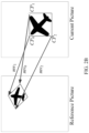
- FIG. 5 shows an example of candidate positions for affine merge mode.
- FIG. 6 shows an example of one coding unit (CU) with sub-blocks and neighboring blocks of the CU.
- FIG. 7 is a block diagram illustrating an example of the architecture for a computer system or other control device that can be utilized to implement various portions of the presently disclosed technology.
- FIG. 8 shows a block diagram of an example embodiment of a mobile device that can be utilized to implement various portions of the presently disclosed technology.
- FIG. 9 is a flowchart for an example method of video processing.
- FIG. 10 is a flowchart for another example method of video processing.
- FIG. 11 shows an example block diagram of a typical High Efficiency Video Coding (HEVC) video encoder and decoder.
- HEVC High Efficiency Video Coding
- Video codecs typically include an electronic circuit or software that compresses or decompresses digital video, and are continually being improved to provide higher coding efficiency.
- a video codec converts uncompressed video to a compressed format or vice versa.
- the compressed format usually conforms to a standard video compression specification, e.g., the High Efficiency Video Coding (HEVC) standard (also known as H.265 or MPEG-H Part 2), the Versatile Video Coding (VVC) standard to be finalized, or other current and/or future video coding standards.
- HEVC High Efficiency Video Coding
- VVC Versatile Video Coding
- Sub-block based prediction is first introduced into the video coding standard by the High Efficiency Video Coding (HEVC) standard.
- HEVC High Efficiency Video Coding
- a block such as a Coding Unit (CU) or a Prediction Unit (PU)
- PU Prediction Unit
- Different sub-blocks may be assigned different motion information, such as reference index or motion vector (MV), and motion compensation (MC) is performed individually for each sub-block.
- FIG. 1 shows an example of sub-block based prediction.
- Embodiments of the disclosed technology may be applied to existing video coding standards (e.g., HEVC, H.265) and future standards to improve runtime performance.
- Section headings are used in the present document to improve readability of the description and do not in any way limit the discussion or the embodiments (and/or implementations) to the respective sections only.
- JEM Joint Exploration Model
- JEM Joint Exploration Model
- HEVC High Efficiency Video Coding
- MCP motion compensation prediction
- a simplified affine transform motion compensation prediction is applied. As shown in FIGS. 2 A and 2 B , the affine motion field of the block is described by two (in the 4-parameter affine model) or three (in the 6-parameter affine model) control point motion vectors, respectively.
- the motion vector field (MVF) of a block is described by the following equation with the 4-parameter affine model and 6-parameter affine model respectively:
- (mv h 0 , mv h 0 ) is motion vector of the top-left corner control point (CP)
- (mv h 1 , mv h 1 ) is motion vector of the top-right corner control point
- (mv h 2 , mv h 2 ) is motion vector of the bottom-left corner control point
- (x, y) represents the coordinate of a representative point relative to the top-left sample within current block.
- the CP motion vectors may be signaled (like in the affine AMVP mode) or derived on-the-fly (like in the affine merge mode).
- w and h are the width and height of the current block. In practice, the division is implemented by right-shift with a rounding operation.
- VTM VVC Test model
- the representative point is defined to be the center position of a sub-block, e.g., when the coordinate of the left-top corner of a sub-block relative to the top-left sample within current block is (xs, ys), the coordinate of the representative point is defined to be (xs+2, ys+2).
- Equations (1) and (2) are implemented as:
- Equation (1) For the 4-parameter affine model shown in Equation (1):
- the motion vectors may be derived as:
- the motion vector of the center sample of each sub-block is calculated according to Equations (1) or (2), and rounded to 1/16 fraction accuracy. Then the motion compensation interpolation filters are applied to generate the prediction of each sub-block with derived motion vector.
- Affine model can be inherited from spatial neighbouring affine-coded block such as left, above, above right, left bottom and above left neighbouring block as shown in FIG. 4 A .
- the neighbour left bottom block A in FIG. 4 A is coded in affine mode as denoted by A0 in FIG. 4 B
- the Control Point (CP) motion vectors mv 0 N , mv 1 N and mv 2 N of the top left corner, above right corner and left bottom corner of the neighbouring CU/PU which contains the block A are fetched.
- the motion vector mv 0 C , mv 1 C and mv 2 C (which is only used for the 6-parameter affine model) of the top left corner/top right/bottom left on the current CU/PU is calculated based on mv 0 N , mv 1 N and mv 2 N .
- sub-block e.g. 4 ⁇ 4 block in VTM
- LT stores mv0
- RT stores mv1 if the current block is affine coded. If the current block is coded with the 6-parameter affine model, LB stores mv2; otherwise (with the 4-parameter affine model), LB stores mv2′.
- Other sub-blocks stores the MVs used for MC.
- a CU when a CU is coded with affine merge mode, e.g., in AF_MERGE mode, it gets the first block coded with affine mode from the valid neighbour reconstructed blocks. And the selection order for the candidate block is from left, above, above right, left bottom to above left as shown in FIG. 4 A .
- the derived CP MVs mv 0 C , mv 1 C and mv 2 C of current block can be used as CP MVs in the affine merge mode. Or they can be used as MVP for affine inter mode in VVC. It should be noted that for the merge mode, if the current block is coded with affine mode, after deriving CP MVs of current block, the current block may be further split into multiple sub-blocks and each block will derive its motion information based on the derived CP MVs of current block.
- VTM wherein only one affine spatial neighboring block may be used to derive affine motion for a block
- inherited affine candidate means that the candidate is derived from the valid neighbor reconstructed block coded with affine mode.
- the scan order for the candidate block is A 1 , B 1 , B 0 , A 0 and B 2 .
- a block is selected (e.g., A 1 )
- the two-step procedure is applied:
- affine merge candidate list if the number of candidates in affine merge candidate list is less than MaxNumAffineCand, constructed affine candidates are insert into the candidate list.
- Constructed affine candidate means the candidate is constructed by combining the neighbor motion information of each control point.
- the motion information for the control points is derived firstly from the specified spatial neighbors and temporal neighbor shown in FIG. 5 .
- T is temporal position for predicting CP4.
- the coordinates of CP1, CP2, CP3 and CP4 is (0, 0), (W, 0), (H, 0) and (W, H), respectively, where W and H are the width and height of current block.
- Motion vectors of three control points are needed to compute the transform parameters in 6-parameter affine model.
- the three control points can be selected from one of the following four combinations ( ⁇ CP1, CP2, CP4 ⁇ , ⁇ CP1, CP2, CP3 ⁇ , ⁇ CP2, CP3, CP4 ⁇ , ⁇ CP1, CP3, CP4 ⁇ ).
- CP1, CP2 and CP3 control points to construct 6-parameter affine motion model, denoted as Affine (CP1, CP2, CP3).
- Motion vectors of two control points are needed to compute the transform parameters in 4-parameter affine model.
- the two control points can be selected from one of the following six combinations ( ⁇ CP1, CP4 ⁇ , ⁇ CP2, CP3 ⁇ , ⁇ CP1, CP2 ⁇ , ⁇ CP2, CP4 ⁇ , ⁇ CP1, CP3 ⁇ , ⁇ CP3, CP4 ⁇ ).
- ⁇ CP1, CP4 ⁇ ⁇ CP1, CP4 ⁇
- CP1 and CP2 control points to construct 4-parameter affine motion model, denoted as Affine (CP1, CP2).
- ATMVP advanced temporal motion vector prediction
- one simplified design is proposed to use the same collocated picture as in HEVC, which is signaled at the slice header, as the collocated picture for ATMVP derivation.
- the MV of the block is scaled using the HEVC temporal MV scaling method, and the scaled MV is used in ATMVP.
- the MV in the spatial candidate list used to derive MV col is selected in the following way: if the reference picture of a candidate MV is the collocated picture, this MV is selected and used as MV col without any scaling. Otherwise, the MV having a reference picture closest to the collocated picture is selected to derive MV col with scaling.
- one default sub-block size that is used for the ATMVP motion derivation is signaled at sequence level.
- one flag is signaled at slice-level to indicate if the default sub-block size is used for the current slice. If the flag is false, the corresponding ATMVP sub-block size is further signaled in the slice header for the slice.
- FIG. 6 shows an example of one CU with four sub-blocks and neighboring blocks.
- an 8 ⁇ 8 CU which contains four 4 ⁇ 4 sub-CUs A, B, C, and D.
- the neighbouring 4 ⁇ 4 blocks in the current frame are labelled as a, b, c, and d.
- the motion derivation for sub-CU A starts by identifying its two spatial neighbours.
- the first neighbour is the N ⁇ N block above sub-CU A (block c). If this block c is not available or is intra coded the other N ⁇ N blocks above sub-CU A are checked (from left to right, starting at block c).
- the second neighbour is a block to the left of the sub-CU A (block b). If block b is not available or is intra coded other blocks to the left of sub-CU A are checked (from top to bottom, staring at block b).
- the motion information obtained from the neighbouring blocks for each list is scaled to the first reference frame for a given list.
- temporal motion vector predictor (TMVP) of sub-block A is derived by following the same procedure of TMVP derivation as specified in HEVC.
- the motion information of the collocated block at location D is fetched and scaled accordingly.
- all available motion vectors (up to 3) are averaged separately for each reference list. The averaged motion vector is assigned as the motion vector of the current sub-CU.
- affine merge mode of VTM-2.0.1 only the first available affine neighbour can be used to derive motion information of affine merge mode.
- JVET-L0366 a candidate list for affine merge mode is constructed by searching valid affine neighbours and combining the neighbor motion information of each control point.
- the affine merge candidate list is constructed as following steps:
- Inherited affine candidate means that the candidate is derived from the affine motion model of its valid neighbor affine coded block.
- the scan order for the candidate positions is: A1, B1, B0, A0 and B2.
- full pruning process is performed to check whether same candidate has been inserted into the list. If a same candidate exists, the derived candidate is discarded.
- Constructed affine candidate means the candidate is constructed by combining the neighbor motion information of each control point.
- the motion information for the control points is derived firstly from the specified spatial neighbors and temporal neighbor shown in FIG. 5 .
- T is temporal position for predicting CP4.
- the coordinates of CP1, CP2, CP3 and CP4 is (0, 0), (W, 0), (H, 0) and (W, H), respectively, where W and H are the width and height of current block.
- Motion information of three control points are needed to construct a 6-parameter affine candidate.
- the three control points can be selected from one of the following four combinations ( ⁇ CP1, CP2, CP4 ⁇ , ⁇ CP1, CP2, CP3 ⁇ , ⁇ CP2, CP3, CP4 ⁇ , ⁇ CP1, CP3, CP4 ⁇ ).
- Combinations ⁇ CP1, CP2, CP3 ⁇ , ⁇ CP2, CP3, CP4 ⁇ , ⁇ CP1, CP3, CP4 ⁇ will be converted to a 6-parameter motion model represented by top-left, top-right and bottom-left control points.
- Motion information of two control points are needed to construct a 4-parameter affine candidate.
- the two control points can be selected from one of the following six combinations ( ⁇ CP1, CP4 ⁇ , ⁇ CP2, CP3 ⁇ , ⁇ CP1, CP2 ⁇ , ⁇ CP2, CP4 ⁇ , ⁇ CP1, CP3 ⁇ , ⁇ CP3, CP4 ⁇ ).
- Combinations ⁇ CP1, CP4 ⁇ , ⁇ CP2, CP3 ⁇ , ⁇ CP2, CP4 ⁇ , ⁇ CP1, CP3 ⁇ , ⁇ CP3, CP4 ⁇ will be converted to a 4-parameter motion model represented by top-left and top-right control points.
- reference index X (X being 0 or 1) of a combination
- the reference index with highest usage ratio in the control points is selected as the reference index of list X, and motion vectors point to difference reference picture will be scaled.
- full pruning process is performed to check whether same candidate has been inserted into the list. If a same candidate exists, the derived candidate is discarded.
- JVET-L0368 proposes the following simplifications for the affine merge mode in JVET-L0366:
- the pruning process for inherited affine candidates is simplified by comparing the coding units covering the neighboring positions, instead of comparing the derived affine candidates in VTM-2.0.1. Up to 2 inherited affine candidates are inserted into affine merge list. The pruning process for constructed affine candidates is totally removed.
- the affine merge candidate list may be renamed with some other names such as sub-block merge candidate list.
- Pairwise average candidates are generated by averaging predefined pairs of candidates in the current merge candidate list, and the predefined pairs are defined as ⁇ (0, 1), (0, 2), (1, 2), (0, 3), (1, 3), (2, 3) ⁇ , where the numbers denote the merge indices to the merge candidate list.
- the averaged motion vectors are calculated separately for each reference list. If both motion vectors are available in one list, these two motion vectors are averaged even when they point to different reference pictures; if only one motion vector is available, use the one directly; if no motion vector is available, keep this list invalid.
- the pairwise average candidates replaces the combined candidates in HEVC standard.
- New Affine merge candidates are generated based on the CPMVs offsets of the first Affine merge candidate. If the first Affine merge candidate enables 4-parameter Affine model, then 2 CPMVs for each new Affine merge candidate are derived by offsetting 2 CPMVs of the first Affine merge candidate; Otherwise (6-parameter Affine model enabled), then 3 CPMVs for each new Affine merge candidate are derived by offsetting 3 CPMVs of the first Affine merge candidate. In Uni-prediction, the CPMV offsets are applied to the CPMVs of the first candidate.
- MV new(L0),i MV old(L0) +MV offset(i)
- MV new(L1),i MV old(L1) +MV offset(i)
- MV new(L0),i MV old(L0) +MV offset(i)
- MV new(L1),i MV old(L1) ⁇ MV offset(i)
- the Affine merge list is increased to 20 for this design.
- the number of potential Affine merge candidates is 31 in total.
- the Affine merge list is kept to 5 as VTM2.0.1 does.
- Four temporal constructed Affine merge candidates are removed to keep the number of potential Affine merge candidates unchanged, i.e., 15 in total.
- the coordinates of CPMV1, CPMV2, CPMV3 and CPMV4 are (0, 0), (W, 0), (H, 0) and (W, H).
- CPMV4 is derived from the temporal MV as shown in FIG. 5 .
- the removed candidates are the following four temporal-related constructed Affine merge candidates: ⁇ CP2, CP3, CP4 ⁇ , ⁇ CP1, CP4 ⁇ , ⁇ CP2, CP4 ⁇ , ⁇ CP3, CP4 ⁇ .
- a combined affine model with CPMVs (MV′ 0 , MV′ 1 , MV′ 2 ) can be derived from those affine models and the current block is predicted by the new affine model.
- (MV 0 , MV 1 , MV 2 ) represents the CPMV at the top-left corner, the top-right corner and bottom-left corner respectively.
- MV is 2-dimension vector noted as (MVx, MVy).
- CPMVs of an original affine model may be derived from an affine-coded spatial or temporal neighboring block for the current block.
- CPMVs of affine models derived from some affine-coded spatial neighboring block are not used to derive the new affine model to be used by the current block.
- CPMVs of an original affine model may be derived from a constructed affine model such as proposed in JVET-K0186.
- CPMVs of some constructed affine models are not used to derive the new affine model to be used by the current block.
- (MV′ 0 , MV′ 1 , MV′ 2 ) (F0(MV 0 1 , . . . , MV 0 N ), F1(MV 1 1 , . . . , MV 1 N ), F2(MV 2 1 , . . . , MV 2 N )), where F0, F1 and F2 are functions.
- Fi may be defined to be average function.
- (MV′ 0 , MV′ 1 , MV′ 2 ) (Average(MV 0 1 , . . . , MV 0 N ), Average(MV 1 1 , . . . , MV 1 N ), Average(MV 2 1 , . . . , MV 2 N )).
- some CPMVs may not exist. For example, MV 2 i does not exist, then w i 2 is set to be 0.
- an original affine model with 4 parameters are first converted into an affine model with 6-parameter before being used to derive the CPMVs of the combined affine model.
- (DiffMV′ 1 , DiffMV′ 2 ) (F1(DiffMV 1 1 , . . . , DiffMV 1 N ), F2(DiffMV 2 1 , . . . , DiffiMV 2 N )), where F1 and F2 are functions.
- (DiffMV′ 1 , DiffMV′ 2 ) (Average(DiffMV 1 1 , . . . , DiffMV 1 N ), Average(DiffMV 2 1 , . . . , DiffMV 2 N )).
- DiffMV′ 1 and/or DiffMV′ 2 is derived from some original CPMVs in one way.
- MV′ 0 is derived in another way;
- (MV′ 0 , MV′ 0 +DiffMV′ 1 ) or (MV′ 0 , MV′ 0 +DiffMV′ 1 , MV′ 0 +DiffMV′ 2 ) is treated as the CPMVs of the combined affine model.
- DiffMV′ 1 and/or DiffMV′ 2 is derived by combining two affine coded spatial neighboring blocks.
- MV′ 0 is copied or scaled from block A2 or block B2 or block B3 in FIG. 5 .
- only original CPMVs referring to the same reference picture can be combined.
- CPMVs referring to different reference pictures should be scaled to the same reference picture before being combined.
- More than one combined affine models can be derived and serve as affine MVP candidates or merge candidates
- affine parameters or CPMVs of each two affine coded spatial neighboring blocks are combined to generate a combined candidate with the affine parameters or CPMVs of a new affine model, and this combined affine model is added into the affine MVP candidate list or affine merge list.
- the combined candidate may be put into the candidate list after normal affine AMVP or merge candidates inherited from spatial neighboring blocks.
- the number of combined candidate put into the candidate list cannot exceed a fixed number such as 5.
- N (N ⁇ 2) temporary predictions for the current block may be firstly generated by N affine models, and the final prediction can be a combination of the temporary predictions.
- the N original predictions for the current block are denoted as P 1 (x,y), . . . , P N (x,y).
- the final prediction is denoted as P′(x,y).
- P′(x,y) Average(P 1 (x,y), . . . , P N (x,y)).
- w i (x,y) is the same for all (x,y).
- P 1 (x,y), . . . , P N (x,y) should be generated by affine models referring to the same reference picture.
- P 1 (x,y), . . . , P N (x,y) should be generated by affine models referring to reference pictures in the same reference list.
- P 1 (x,y) and P 2 (x,y) cannot be combined to as a combined candidate if they are the two predictions referring to reference list 0 and reference list 1 of a bi-prediction candidate already in the candidate list.
- pairwise average candidate is only applied on normal merge candidate list.
- multiple hypotheses for affine models are not applied to the affine merge candidate list.
- Embodiments of the disclosed technology inherit the 6-parameter affine model with reduced memory requirements, and may improve video coding efficiency and enhance both existing and future video coding standards is elucidated in the following examples described for various implementations.
- the coordinate of the top-left corner/top-right corner/bottom-left corner/bottom-right corner of the affine coded above or left neighboring CU are (LTNx, LTNy)/(RTNx, RTNy)/(LBNx, LBNy)/(RBNx, RBNy), respectively;
- the coordinate of the top-left corner/top-right corner/bottom-left corner/bottom-right corner of the current CU are (LTCx,LTCy)/(RTCx, RTCy)/(LBCx, LBCy)/(RBCx, RBCy), respectively;
- the width and height of the affine coded above or left neighboring CU are w′ and h′, respectively; the width and height of
- MV is 2-dimension vector noted as (MVx, MVy).
- sub-block merge candidate list when other kinds of sub-block merge candidate such as ATMVP candidate is also put into the merge candidate list.
- the combined affine merge candidates are put into the affine merge candidate list right after the neighboring inherited affine merge candidates have been put into the list.
- the combined affine merge candidates are put into the affine merge candidate list right after the constructed affine merge candidates have been put into the list.
- Example 3 In one example, a combined affine merge candidate is compared with existing affine merge candidates already in the list. If it is identical to an existing one, then it is not put into the list. The procedure is called “pruning”. Alternatively, a combined affine merge candidate is not compared with existing affine merge candidates. In other words, no pruning process.
- Example 4 whether to and how to generate the combined affine merge candidate may depend on the inter directions (List 0 prediction, List 1 prediction, or Bi-prediction) of the affine merge candidates X0 and X1, which are used to generate the combined affine merge candidate.
- FIG. 7 is a block diagram illustrating an example of the architecture for a computer system or other control device 2600 that can be utilized to implement various portions of the presently disclosed technology.
- the computer system 2600 includes one or more processors 2605 and memory 2610 connected via an interconnect 2625 .
- the interconnect 2625 may represent any one or more separate physical buses, point to point connections, or both, connected by appropriate bridges, adapters, or controllers.
- the interconnect 2625 may include, for example, a system bus, a Peripheral Component Interconnect (PCI) bus, a HyperTransport or industry standard architecture (ISA) bus, a small computer system interface (SCSI) bus, a universal serial bus (USB), IIC (I2C) bus, or an Institute of Electrical and Electronics Engineers (IEEE) standard 674 bus, sometimes referred to as “Firewire.”
- PCI Peripheral Component Interconnect
- ISA HyperTransport or industry standard architecture
- SCSI small computer system interface
- USB universal serial bus
- I2C IIC
- IEEE Institute of Electrical and Electronics Engineers
- the processor(s) 2605 may include central processing units (CPUs) to control the overall operation of, for example, the host computer. In certain embodiments, the processor(s) 2605 accomplish this by executing software or firmware stored in memory 2610 .
- the processor(s) 2605 may be, or may include, one or more programmable general-purpose or special-purpose microprocessors, digital signal processors (DSPs), programmable controllers, application specific integrated circuits (ASICs), programmable logic devices (PLDs), or the like, or a combination of such devices.
- the memory 2610 can be or include the main memory of the computer system.
- the memory 2610 represents any suitable form of random access memory (RAM), read-only memory (ROM), flash memory, or the like, or a combination of such devices.
- RAM random access memory
- ROM read-only memory
- flash memory or the like, or a combination of such devices.
- the memory 2610 may contain, among other things, a set of machine instructions which, when executed by processor 2605 , causes the processor 2605 to perform operations to implement embodiments of the presently disclosed technology.
- the network adapter 2615 provides the computer system 2600 with the ability to communicate with remote devices, such as the storage clients, and/or other storage servers, and may be, for example, an Ethernet adapter or Fiber Channel adapter.
- FIG. 8 shows a block diagram of an example embodiment of a mobile device 2700 that can be utilized to implement various portions of the presently disclosed technology.
- the mobile device 2700 can be a laptop, a smartphone, a tablet, a camcorder, or other types of devices that are capable of processing videos.
- the mobile device 2700 includes a processor or controller 2701 to process data, and memory 2702 in communication with the processor 2701 to store and/or buffer data.
- the processor 2701 can include a central processing unit (CPU) or a microcontroller unit (MCU).
- the processor 2701 can include a field-programmable gate-array (FPGA).
- FPGA field-programmable gate-array
- the mobile device 2700 includes or is in communication with a graphics processing unit (GPU), video processing unit (VPU) and/or wireless communications unit for various visual and/or communications data processing functions of the smartphone device.
- the memory 2702 can include and store processor-executable code, which when executed by the processor 2701 , configures the mobile device 2700 to perform various operations, e.g., such as receiving information, commands, and/or data, processing information and data, and transmitting or providing processed information/data to another device, such as an actuator or external display.
- the memory 2702 can store information and data, such as instructions, software, values, images, and other data processed or referenced by the processor 2701 .
- the mobile device 2700 includes an input/output (I/O) unit 2703 to interface the processor 2701 and/or memory 2702 to other modules, units or devices.
- I/O unit 2703 can interface the processor 2701 and memory 2702 with to utilize various types of wireless interfaces compatible with typical data communication standards, e.g., such as between the one or more computers in the cloud and the user device.
- the mobile device 2700 can interface with other devices using a wired connection via the I/O unit 2703 .
- the mobile device 2700 can also interface with other external interfaces, such as data storage, and/or visual or audio display devices 2704 , to retrieve and transfer data and information that can be processed by the processor, stored in the memory, or exhibited on an output unit of a display device 2704 or an external device.
- the display device 2704 can display a video frame modified based on the MVPs in accordance with the disclosed technology.
- method 900 may be implemented at a video decoder/encoder.
- FIG. 9 shows a flowchart of an exemplary method for video coding.
- the method 900 includes, at step 910 , generating, for a bitstream representation of a current block, an updated merge candidate list by adding at least one combined merge candidate to a merge candidate list.
- the at least one combined merge candidate may include one or more combined affine merge candidates.
- the at least one combined merge candidate is added to a first merge candidate list that includes sub-block prediction based merge candidates like affine or ATMVP merge candidates.
- the first merge candidate list is different from a second merge candidate list that includes normal merge candidates (e.g., HEVC merge candidates).
- the at least one combined merge candidate may be stored separately from normal HEVC merge candidates, and along with other sub-block prediction based merge candidates.
- the method 900 further includes the step of adding, immediately prior to the generating, one or more neighboring inherited affine merge candidates to the merge candidate list.
- the method 900 further includes the step of adding, immediately prior to the generating, one or more constructed affine merge candidates to the merge candidate list.
- the merge candidate list comprises N ⁇ 2 affine merge candidates.
- the at least one combined merge candidate is based on M of the N affine merge candidates, wherein the M of the N affine merge candidates are selected from a first K of the N affine merge candidates, and wherein M and K are integers.
- the at least one combined merge candidate is based on M of the N affine merge candidates, wherein the M of the N affine merge candidates are selected from a last K of the N affine merge candidates, and wherein M and K are integers.
- the at least one combined merge candidate comprises a first combined merge candidate with control point motion vectors (CPMVs) denoted (MV′ 0 , MV′′, MV′ 2 ), and wherein the N affine merge candidates comprise a first affine merge candidate with CPMVs denoted (MV 0 C1 , MV 1 C1 , MV 2 C1 ) and a second affine merge candidate with CPMVs denoted (MV 0 C2 , MV 1 C2 , MV 2 C2 ).
- CPMVs control point motion vectors
- MV′ 0 MV 0 C1
- MV′ 1 MV 0 C1 +Average(DiffMV C1 1 , DiffMV C2 1 )
- MV′ 2 MV 0 C1 +Average(DiffMV C1 2 , DiffMV C2 2 )
- DiffMV C1 1 MV C1 i ⁇ MV C1 0
- DiffMV C1 2 MV C1 2 ⁇ MV C1 0
- DiffMV C2 1 MV C2 1 ⁇ MV C2 0
- DiffMV C2 2 MV C2 2 ⁇ MV C2 0 .
- the first affine merge candidate is associated with a first reference picture
- the second affine merge candidate is associated with a second reference picture that is different from the first reference picture
- the step of generating the updated merge candidate list may further include determining that a first combined merge candidate of the at least one combined merge candidate is not identical to any merge candidate in the merge candidate list, and adding the first combined merge candidate to the merge candidate list.
- the method 900 may include the steps of determining that a second combined merge candidate of the at least at least one combined merge candidate is identical to at least one merge candidate in the merge candidate list, and excluding the second combined merge candidate from the merge candidate list.
- the method 900 may further include generating, based on inter directions of two affine merge candidates in the merge candidate list, the at least one combined merge candidate.
- the method 900 includes, at step 920 , performing, based on the updated merge candidate list, a conversion between the bitstream representation and the current block.
- the conversion generates the current block from the bitstream representation (e.g., as might be implemented in a video decoder). In other embodiments, the conversion generates the bitstream representation from the current block (e.g., as might be implemented in a video encoder).
- FIG. 10 is a flowchart representation of a method 1000 of video coding.
- the method 1000 includes generating ( 1010 ), during a conversion between a current block of video and a bitstream representation of the current block, an updated merge candidate list by adding at least one combined merge candidate to a first merge candidate list; and performing ( 1020 ), the conversion by using the updated merge candidate list.
- the first merge candidate list comprises one or more sub-block prediction based merge candidates.
- the one or more sub-block prediction based merge candidates comprise affine merge candidates or advanced temporal motion vector prediction (ATMVP) merge candidates.
- ATMVP advanced temporal motion vector prediction
- the conversion generates the current block from the bitstream representation.
- the conversion generates the bitstream representation from the current block.
- the at least one combined merge candidate comprises one or more combined affine merge candidates.
- the method further comprising: immediately after adding one or more neighboring inherited affine merge candidates to the first merge candidate list, adding the at least one combined merge candidate to the first merge candidate list.
- the method further comprising: immediately after adding one or more constructed affine merge candidates to the first merge candidate list, adding the at least one combined merge candidate to the first merge candidate list.
- the first merge candidate list includes a first affine merge candidate list comprising multiple affine merge candidates with control point motion vectors, and a combined affine model with control point motion vectors (CPMVs) of the at least one combined merge candidate are derived based on the multiple affine merge candidates.
- CPMVs control point motion vectors
- the combined affine model with control point motion vectors (CPMVs) of the at least one combined merge candidate is derived from affine models of M affine merge candidates in K affine merge candidates, wherein the K affine merge candidates are the first K affine merge candidates of the multiple affine merge candidates in the first affine merge candidate list, and wherein M and K are integers, K is larger or equal to M.
- a combined affine model with control point motion vectors (CPMVs) of the at least one combined merge candidate is derived from affine models of M affine merge candidates in K affine merge candidates, wherein the K affine merge candidates are the last K affine merge candidates prior to the at least one combined merge candidate in the first affine merge candidate list, and wherein M and K are integers, K is larger or equal to M.
- CPMVs control point motion vectors
- the at least one combined merge candidate comprises a first combined merge candidate with control point motion vectors (CPMVs) denoted (MV′ 0 , MV′ 1 , MV′ 2 ), and wherein the multiple affine merge candidates comprise a first affine merge candidate with CPMVs denoted (MV 0 C1 , MV 1 C1 , MV 2 C1 ) and a second affine merge candidate with CPMVs denoted (MV 0 C2 , MV 1 C2 , MV 2 C2 ) and/or a third affine merge candidate with CPMVs denoted (MV 0 C3 , MV 1 C3 , MV 2 C3 ), C1, C2, C3 represents the indices of the multiple affine merge candidate.
- CPMVs control point motion vectors
- the at least one combined merge candidate comprises a first combined merge candidate with control point motion vectors (CPMVs) denoted (MV′ 0 , MV′ 1 ), and wherein the multiple affine merge candidates comprise a first affine merge candidate with CPMVs denoted (MV 0 C1 , MV 1 C1 ) and a second affine merge candidate with CPMVs denoted (MV 0 C2 , MV 1 C2 ) and/or a third affine merge candidate with CPMVs denoted (MV 0 C3 , MV 1 C3 , MV 2 C3 ), C1, C2, C3 represents the indices of the multiple affine merge candidate.
- CPMVs control point motion vectors
- the CPMVs of the first affine merge candidate are associated with a first reference picture
- the CPMVs of the second affine merge candidate are associated with a second reference picture that is different from the first reference picture.
- the CPMVs of the first affine merge candidate and the CPMVs of the second affine merge candidate are scaled to same reference picture before they are combined, wherein the same reference picture is one of the first reference picture and the second reference picture or a fixed reference picture.
- the CPMVs of the first affine merge candidate and the CPMVs of the second affine merge candidate are combined without any scaling.
- the CPMVs of the first affine merge candidate and the CPMVs of the second affine merge candidate cannot be combined.
- the at least one combined merge candidate is derived by using pairs of affine merge candidates of the multiple affine merge candidates, and the at least one combined merge candidate is put into the first affine merge candidate list in a predetermined order.
- one affine merge candidate with an index in a pair of affine merge candidates is not available, or if one affine merge candidate with an index in a pair of affine merge candidates is a combined affine merge candidate, or if one affine merge candidate with an index in a pair of affine merge candidates is a constructed affine merge candidate, or if one affine merge candidate with an index in a pair of affine merge candidates is an advanced temporal motion vector prediction (ATMVP) merge candidate, or if one affine merge candidate with an index in a pair of affine merge candidates is a zero affine merge candidate, this pair is skipped and not used to derive the at least one combined affine merge candidate.
- ATMVP advanced temporal motion vector prediction
- the at least one combined merge candidate is derived by using groups of affine merge candidates of the multiple affine merge candidates, and the at least one combined merge candidate is put into the first affine merge candidate list in a predetermined order.
- one affine merge candidate with an index in a group of affine merge candidates is not available, or if one affine merge candidate with an index in a group of affine merge candidates is a combined affine merge candidate, or if one affine merge candidate with an index in a group of affine merge candidates is a constructed affine merge candidate, or if one affine merge candidate with an index in a group of affine merge candidates is an advanced temporal motion vector prediction (ATMVP) merge candidate, or if one affine merge candidate with an index in a group of affine merge candidates is a zero affine merge candidate, this group is skipped and not used to derive the at least one combined affine merge candidate.
- ATMVP advanced temporal motion vector prediction
- the generating the updated merge candidate list comprises: determining whether a first combined merge candidate of the at least at least one combined merge candidate is identical to any merge candidate in the first merge candidate list; if no, adding the first combined merge candidate to the first merge candidate list, and if yes, discarding the first combined merge candidate.
- the method further comprising: generating, based on inter directions of a first affine merge candidate and a second affine merge candidate in the first merge candidate list, the at least one combined merge candidate.
- the at least one combined affine merge candidate applies Bi-prediction, with CPMVs in List 0 equal to CPMVs of the first affine merge candidate and CPMVs in List 1 equal to CPMVS of the second affine merge candidate.
- the at least one combined affine merge candidate applies Bi-prediction, with CPMVs in List 0 equal to CPMVs of the second affine merge candidate and CPMVs in List 1 equal to CPMVS of the first affine merge candidate.
- the at least one combined affine merge candidate applies List 0 prediction, with CPMVs in List 0 equal to a combination of CPMVs of the first affine merge candidate and CPMVs of the second affine merge candidate.
- the at least one combined affine merge candidate applies Bi-prediction, with CPMVs in List 0 equal to a combination of CPMVs of the first affine merge candidate and CPMVs of the second affine merge candidate.
- the at least one combined affine merge candidate applies List 1 prediction, with CPMVs in List 1 equal to a combination of CPMVs of the first affine merge candidate and CPMVs of the second affine merge candidate.
- the at least one combined affine merge candidate applies Bi-prediction, with CPMVs in List 0 equal to a combination of CPMVs in List 0 of the first affine merge candidate and CPMVs in List 0 of the second affine merge candidate, and CPMVs in List 1 equal to CPMVs in List 1 of the second affine merge candidate.
- the at least one combined affine merge candidate applies Bi-prediction, with CPMVs in List 1 equal to a combination of CPMVs in List 1 of the first affine merge candidate and CPMVs in List 1 of the second affine merge candidate, and CPMVs in List 0 equal to CPMVs in List 0 of the second affine merge candidate.
- the at least one combined affine merge candidate applies Bi-prediction, with CPMVs in List 0 equal to a combination of CPMVs in List 0 of the second affine merge candidate and CPMVs in List 0 of the first affine merge candidate, and CPMVs in List 1 equal to CPMVs in List 1 of the first affine merge candidate.
- the at least one combined affine merge candidate applies Bi-prediction, with CPMVs in List 1 equal to a combination of CPMVs in List 1 of the second affine merge candidate and CPMVs in List 1 of the first affine merge candidate, and CPMVs in List 0 equal to a combination of CPMVs in List 0 of the first affine merge candidate and CPMVs in List 0 of the second affine merge candidate.
- the first merge candidate list is an affine merge candidate list or a sub-block merge candidate list.
- FIG. 11 shows an example block diagram of a typical HEVC video encoder and decoder 1100 .
- An encoding algorithm producing an HEVC compliant bitstream would typically proceed as follows. Each picture is split into block-shaped regions, with the exact block partitioning being conveyed to the decoder. The first picture of a video sequence (and the first picture at each clean random access point into a video sequence) is coded using only intra-picture prediction (that uses some prediction of data spatially from region-to-region within the same picture, but has no dependence on other pictures). For all remaining pictures of a sequence or between random access points, inter-picture temporally predictive coding modes are typically used for most blocks.
- the encoding process for inter-picture prediction consists of choosing motion data comprising the selected reference picture and motion vector (MV) to be applied for predicting the samples of each block.
- the encoder and decoder generate identical inter-picture prediction signals by applying motion compensation (MC) using the MV and mode decision data, which are transmitted as side information.
- MC motion compensation
- the residual signal of the intra- or inter-picture prediction which is the difference between the original block and its prediction, is transformed by a linear spatial transform.
- the transform coefficients are then scaled, quantized, entropy coded, and transmitted together with the prediction information.
- the encoder duplicates the decoder processing loop (see gray-shaded boxes in FIG. 11 ) such that both will generate identical predictions for subsequent data. Therefore, the quantized transform coefficients are constructed by inverse scaling and are then inverse transformed to duplicate the decoded approximation of the residual signal. The residual is then added to the prediction, and the result of that addition may then be fed into one or two loop filters to smooth out artifacts induced by block-wise processing and quantization.
- the final picture representation (that is a duplicate of the output of the decoder) is stored in a decoded picture buffer to be used for the prediction of subsequent pictures.
- the order of encoding or decoding processing of pictures often differs from the order in which they arrive from the source; necessitating a distinction between the decoding order (e.g., bitstream order) and the output order (e.g., display order) for a decoder.
- the decoding order e.g., bitstream order
- the output order e.g., display order
- Video material to be encoded by HEVC is generally expected to be input as progressive scan imagery (either due to the source video originating in that format or resulting from deinterlacing prior to encoding).
- No explicit coding features are present in the HEVC design to support the use of interlaced scanning, as interlaced scanning is no longer used for displays and is becoming substantially less common for distribution.
- a metadata syntax has been provided in HEVC to allow an encoder to indicate that interlace-scanned video has been sent by coding each field (i.e., the even or odd numbered lines of each video frame) of interlaced video as a separate picture or that it has been sent by coding each interlaced frame as an HEVC coded picture. This provides an efficient method of coding interlaced video without burdening decoders with a need to support a special decoding process for it.
- the disclosed and other embodiments, modules and the functional operations described in this document can be implemented in digital electronic circuitry, or in computer software, firmware, or hardware, including the structures disclosed in this document and their structural equivalents, or in combinations of one or more of them.
- the disclosed and other embodiments can be implemented as one or more computer program products, i.e., one or more modules of computer program instructions encoded on a computer readable medium for execution by, or to control the operation of, data processing apparatus.
- the computer readable medium can be a machine-readable storage device, a machine-readable storage substrate, a memory device, a composition of matter effecting a machine-readable propagated signal, or a combination of one or more them.
- data processing apparatus encompasses all apparatus, devices, and machines for processing data, including by way of example a programmable processor, a computer, or multiple processors or computers.
- the apparatus can include, in addition to hardware, code that creates an execution environment for the computer program in question, e.g., code that constitutes processor firmware, a protocol stack, a database management system, an operating system, or a combination of one or more of them.
- a propagated signal is an artificially generated signal, e.g., a machine-generated electrical, optical, or electromagnetic signal, that is generated to encode information for transmission to suitable receiver apparatus.
- a computer program (also known as a program, software, software application, script, or code) can be written in any form of programming language, including compiled or interpreted languages, and it can be deployed in any form, including as a stand-alone program or as a module, component, subroutine, or other unit suitable for use in a computing environment.
- a computer program does not necessarily correspond to a file in a file system.
- a program can be stored in a portion of a file that holds other programs or data (e.g., one or more scripts stored in a markup language document), in a single file dedicated to the program in question, or in multiple coordinated files (e.g., files that store one or more modules, sub programs, or portions of code).
- a computer program can be deployed to be executed on one computer or on multiple computers that are located at one site or distributed across multiple sites and interconnected by a communication network.
- the processes and logic flows described in this document can be performed by one or more programmable processors executing one or more computer programs to perform functions by operating on input data and generating output.
- the processes and logic flows can also be performed by, and apparatus can also be implemented as, special purpose logic circuitry, e.g., an FPGA (field programmable gate array) or an ASIC (application specific integrated circuit).
- processors suitable for the execution of a computer program include, by way of example, both general and special purpose microprocessors, and any one or more processors of any kind of digital computer.
- a processor will receive instructions and data from a read only memory or a random-access memory or both.
- the essential elements of a computer are a processor for performing instructions and one or more memory devices for storing instructions and data.
- a computer will also include, or be operatively coupled to receive data from or transfer data to, or both, one or more mass storage devices for storing data, e.g., magnetic, magneto optical disks, or optical disks.
- mass storage devices for storing data, e.g., magnetic, magneto optical disks, or optical disks.
- a computer need not have such devices.
- Computer readable media suitable for storing computer program instructions and data include all forms of non-volatile memory, media and memory devices, including by way of example semiconductor memory devices, e.g., EPROM, EEPROM, and flash memory devices; magnetic disks, e.g., internal hard disks or removable disks; magneto optical disks; and CD ROM and DVD-ROM disks.
- semiconductor memory devices e.g., EPROM, EEPROM, and flash memory devices
- magnetic disks e.g., internal hard disks or removable disks
- magneto optical disks e.g., CD ROM and DVD-ROM disks.
- the processor and the memory can be supplemented by, or incorporated in, special purpose logic circuitry.
Abstract
Description
-
- (a) Firstly, use the three corner motion vectors of the CU covering the block to derive two/three control points of current block; and
- (b) Based on the control points of current block to derive sub-block motion for each sub-block within current block.
-
- For CP1, the checking priority is B2→B3→A2. B2 is used if it is available. Otherwise, if B2 is unavailable, B3 is used. If both B2 and B3 are unavailable, A2 is used. If all the three candidates are unavailable, the motion information of CP1 cannot be obtained.
- For CP2, the checking priority is B1→B0;
- For CP3, the checking priority is A1→A0;
- For CP4, T is used.
-
- {CP1, CP2, CP3}, {CP1, CP2, CP4}, {CP1, CP3, CP4}, {CP2, CP3, CP4}, {CP1, CP2}, {CP1, CP3}, {CP2, CP3}, {CP1, CP4}, {CP2, CP4}, {CP3, CP4}
-
- The collocated pictures of different ATMVP CUs may not be the same if multiple reference pictures are used. This means the motion fields of multiple reference pictures need to be fetched.
- The motion information of each ATMVP CU is always derived based on 4×4 units, resulting in multiple invocations of motion derivation and motion compensation for each 4×4 sub-block inside one ATMVP CU.
-
- For CP1, the checking priority is B2→B3→A2. B2 is used if it is available. Otherwise, if B2 is unavailable, B3 is used. If both B2 and B3 are unavailable, A2 is used. If all the three candidates are unavailable, the motion information of CP1 cannot be obtained.
- For CP2, the checking priority is B1→B0;
- 0 For CP3, the checking priority is A1→A0;
- For CP4, T is used.
-
- {CP1, CP2, CP3}, {CP1, CP2, CP4}, {CP1, CP3, CP4}, {CP2, CP3, CP4}, {CP1, CP2}, {CP1, CP3}, {CP2, CP3}, {CP1, CP4}, {CP2, CP4}, {CP3, CP4}
MVnew(L0),i=MVold(L0)+MVoffset(i)
MVnew(L1),i=MVold(L1)+MVoffset(i)
MVnew(L0),i=MVold(L0)+MVoffset(i)
MVnew(L1),i=MVold(L1)−MVoffset(i)
-
- Offset set=1 (4, 0), (0, 4), (−4, 0), (0, −4), (−4, −4), (4, −4), (4, 4), (−4, 4), (8, 0), (0, 8), (−8, 0), (0, −8), (−8, −8), (8, −8), (8, 8), (−8, 8) 1.
-
- Offset set={(4, 0), (0, 4), (−4, 0), (0, −4)}.
-
- (a) In one example, the affine model of a combined affine merge candidate is generated as a multiple-hypothesis affine model.
- (i) A combined affine model with CPMVs (MV′0, MV′1, MV′2) can be derived from affine models of M (such as 2) affine merge candidates in the first K (such as 4) affine merge candidates already in the affine merge candidate list.
- (ii) A combined affine model with CPMVs (MV′0, MV′1, MV′2) can be derived from affine models of M (such as 2) affine merge candidates in the last K (such as 4) affine merge candidates already in the affine merge candidate list.
- (iii) In one example, a combined affine merge candidate is derived as (MV′0, MV′1, MV′2)=(Average(MV0 C1, MV0 C2), Average(MV1 C1, MV1 C2), Average(MV2 C1, MV2 C2)). Alternatively, (MV′0, MV′1), (Average(MV0 C1,MV0 C2), Average(MV1 C1, MV1 C2)) and the current block applies the 4-parameter affine model.
- (iv) In one example, DiffMVC1 1=MVC1 1−MVC1 0 and DiffMVC1 2=MVC1 2−MVC1 0, DiffMVC2 1=MVC2 1−MVC2 0 and DiffMVC2 2=MVC2 2−MVC2 0. Then (MV′0, MV′1, MV′2)=(MV0 C1, MV0 C1+Average(DiffMVC1 1, DiffMVC2 1), MV0 C1+Average(DiffMVC1 2, DiffMVC2 2)). Alternatively, (MV′0, MV′1)=(MV0 C1, MV0 C1+Average(DiffMVC1 1, DiffMVC2 1)) and the current block applies the 4-parameter affine model.
- (v) In one example, DiffMVC1 1=MVC1 1−MVC1 0 and DiffMVC1 2=MVC1 2−MVC1 0, DiffMVC2 1=MVC2 1−MVC2 0 and DiffMVC2 2=MVC2 2−MVC2 0. Then (MV′0, MV′1, MV′2)=(MV0 C3, MV0 C3+Average(DiffMVC1 1, DiffMVC2 1), MV0 C3+Average(DiffMVC1 2, DiffMVC1 2)). Alternatively, (MV′0, MV′1)=(MV0 C3, MV0 C3+Average(DiffMVC1 1, DiffMVC2 1)) and the current block applies the 4-parameter affine model.
- (vi) In one example, DiffMVC1 1=MVC1 1−MVC1 0 and DiffMVC1 2=MVC1 2−MVC1 0. Then (MV′0, MV′1, MV′2)=(Average(MV0 C1, MV0 C2), Average(MV0 C1, MV0 C2)+DiffMVC1 1, Average(MV0 C1, MV0 C2)+DiffMVC1 2). Alternatively, (MV′0, MV′1)=(Average(MV0 C1, MV0 C2), Average(MV0 C1, MV0 C2)+DiffMVC1 1, and the current block applies the 4-parameter affine model.
- (vii) In one example, DiffMVC1 1=MVC1 1−MVC1 0 and DiffMVC1 2=MVC1 2−MVC1 0. Then (MV′0, MV′1, MV′2)=(Average(MV0 C2, MV0 C3), Average(MV0 C2, MV0 C3)+DiffMVC1 1, Average(MV0 C2, MV0 C3)+DiffMVC1 2). Alternatively, (MV′0, MV′1)=(Average(MV0 C2, MV0 C3), Average(MV0 C2, MV0 C3)+DiffMVC1 1, and the current block applies the 4-parameter affine model.
- (viii) If (MV0 C1, MV1 C1, MV2 C1) and (MV0 C2, MV1 C2, MV2 C2) refers to different reference pictures then:
- (1) For example, they are scaled to the same reference picture before the combination process. The same reference picture can be one of the two different reference pictures, such as the one with a smaller reference index or the one with a smaller POC distance to the current picture, or it can be a fixed reference picture such as the reference picture with reference index equal to 0.
- (2) Alternatively, they are combined without any scaling.
- (3) Alternatively, they cannot be combined.
- (ix) Several pairs of C1, C2 can be used to derive the combined affine merge candidates with one or some methods above, and these candidates are put into the affine merge candidate list in a predefined order. For example, pairs {(0, 1), (0, 2), (1, 2), (0, 3), (1, 3), (2, 3)} are used to derive the combined affine merge candidates and then put into the affine merge candidate list in order.
- (1) If one candidate with a index in a pair is not available, then this pair is skipped and not to derive a combined affine merge candidate.
- (2) If one candidate with an index in a pair is a combined affine merge candidate, then this pair is skipped and not to derive a combined affine merge candidate.
- (3) If one candidate with an index in a pair is a constructed affine merge candidate, then this pair is skipped and not to derive a combined affine merge candidate.
- (4) If one candidate with an index in a pair is an ATMVP (or a spatial TMVP) merge candidate, then this pair is skipped and not to derive a combined affine merge candidate.
- (5) If one candidate with an index in a pair is a zero affine merge candidate, then this pair is skipped and not to derive a combined affine merge candidate.
- (x) Several groups of C1, C2 and C3 can be used to derive the combined affine merge candidates with one or some methods above, and these candidates are put into the affine merge candidate list in a predefined order. For example, groups {(0, 1, 2), (1, 2, 3), (0, 1, 3), (0, 2, 3), (1, 0, 2), (1, 0, 3)} are used to derive the combined affine merge candidates and then put into the affine merge candidate list in order.
- (1) If one candidate with an index in a group is not available, then this pair is skipped and not to derive a combined affine merge candidate.
- (2) If one candidate with an index in a group is a combined affine merge candidate, then this pair is skipped and not to derive a combined affine merge candidate.
- (3) If one candidate with an index in a group is a constructed affine merge candidate, then this pair is skipped and not to derive a combined affine merge candidate.
- (4) If one candidate with an index in a group is an ATMVP (or a spatial TMVP) merge candidate, then this pair is skipped and not to derive a combined affine merge candidate.
- (5) If one candidate with an index in a group is a zero affine merge candidate, then this pair is skipped and not to derive a combined affine merge candidate.
- (xi) The combined affine merge candidates may be generated with any other methods, such as the multiple-hypothesis on affine prediction methods.
- (a) In one example, the affine model of a combined affine merge candidate is generated as a multiple-hypothesis affine model.
Claims (17)
Applications Claiming Priority (4)
| Application Number | Priority Date | Filing Date | Title |
|---|---|---|---|
| WOPCT/CN2018/109329 | 2018-10-08 | ||
| CNPCT/CN2018/109329 | 2018-10-08 | ||
| CN2018109329 | 2018-10-08 | ||
| PCT/IB2019/058543 WO2020075053A1 (en) | 2018-10-08 | 2019-10-08 | Generation and usage of combined affine merge candidate |
Related Parent Applications (1)
| Application Number | Title | Priority Date | Filing Date |
|---|---|---|---|
| PCT/IB2019/058543 Continuation WO2020075053A1 (en) | 2018-10-08 | 2019-10-08 | Generation and usage of combined affine merge candidate |
Publications (2)
| Publication Number | Publication Date |
|---|---|
| US20210227207A1 US20210227207A1 (en) | 2021-07-22 |
| US11825074B2 true US11825074B2 (en) | 2023-11-21 |
Family
ID=68296562
Family Applications (1)
| Application Number | Title | Priority Date | Filing Date |
|---|---|---|---|
| US17/220,301 Active 2039-11-15 US11825074B2 (en) | 2018-10-08 | 2021-04-01 | Generation and usage of combined affine merge candidate |
Country Status (3)
| Country | Link |
|---|---|
| US (1) | US11825074B2 (en) |
| CN (1) | CN111010571B (en) |
| WO (1) | WO2020075053A1 (en) |
Families Citing this family (5)
| Publication number | Priority date | Publication date | Assignee | Title |
|---|---|---|---|---|
| WO2019235822A1 (en) * | 2018-06-04 | 2019-12-12 | 엘지전자 주식회사 | Method and device for processing video signal by using affine motion prediction |
| MX2021007018A (en) * | 2018-12-13 | 2021-07-21 | Beijing Dajia Internet Information Tech Co Ltd | Method for deriving constructed affine merge candidates. |
| EP3905688A4 (en) * | 2018-12-28 | 2022-09-28 | JVCKENWOOD Corporation | Dynamic-image encoding device, dynamic-image encoding method, dynamic-image encoding program, dynamic-image decoding device, dynamic-image decoding method, and dynamic-image decoding program |
| CN117321994A (en) * | 2021-04-09 | 2023-12-29 | 抖音视界有限公司 | Method, apparatus and medium for video processing |
| WO2023051600A1 (en) * | 2021-09-28 | 2023-04-06 | Beijing Bytedance Network Technology Co., Ltd. | Method, apparatus and medium for video processing |
Citations (31)
| Publication number | Priority date | Publication date | Assignee | Title |
|---|---|---|---|---|
| US20130336406A1 (en) | 2012-06-14 | 2013-12-19 | Qualcomm Incorporated | Redundancy removal for merge/skip mode motion information candidate list construction |
| US8964845B2 (en) | 2011-12-28 | 2015-02-24 | Microsoft Corporation | Merge mode for motion information prediction |
| US20150341664A1 (en) | 2013-01-09 | 2015-11-26 | Yi-Wen Chen | Method and apparatus of disparity vector derivation in three-dimensional video coding |
| US20160219278A1 (en) | 2015-01-26 | 2016-07-28 | Qualcomm Incorporated | Sub-prediction unit based advanced temporal motion vector prediction |
| US9432685B2 (en) | 2013-12-06 | 2016-08-30 | Qualcomm Incorporated | Scalable implementation for parallel motion estimation regions |
| CN106105191A (en) | 2014-03-19 | 2016-11-09 | 株式会社Kt | For the method and apparatus processing multiview video signal |
| US9525861B2 (en) | 2012-03-14 | 2016-12-20 | Qualcomm Incorporated | Disparity vector prediction in video coding |
| US9591325B2 (en) | 2015-01-27 | 2017-03-07 | Microsoft Technology Licensing, Llc | Special case handling for merged chroma blocks in intra block copy prediction mode |
| US9609347B2 (en) | 2013-04-04 | 2017-03-28 | Qualcomm Incorporated | Advanced merge mode for three-dimensional (3D) video coding |
| US9716899B2 (en) | 2013-06-27 | 2017-07-25 | Qualcomm Incorporated | Depth oriented inter-view motion vector prediction |
| US20170289566A1 (en) | 2014-09-26 | 2017-10-05 | Vid Scale, Inc. | Intra block copy coding with temporal block vector prediction |
| TW201739252A (en) | 2016-03-15 | 2017-11-01 | 聯發科技股份有限公司 | Method and apparatus of video coding with affine motion compensation |
| US9924168B2 (en) | 2012-10-05 | 2018-03-20 | Hfi Innovation Inc. | Method and apparatus of motion vector derivation 3D video coding |
| US20180098063A1 (en) | 2016-10-05 | 2018-04-05 | Qualcomm Incorporated | Motion vector prediction for affine motion models in video coding |
| US10045014B2 (en) | 2013-07-15 | 2018-08-07 | Mediatek Singapore Pte. Ltd. | Method of disparity derived depth coding in 3D video coding |
| CN108432250A (en) | 2016-01-07 | 2018-08-21 | 联发科技股份有限公司 | The method and device of affine inter-prediction for coding and decoding video |
| US10057594B2 (en) | 2013-04-02 | 2018-08-21 | Vid Scale, Inc. | Enhanced temporal motion vector prediction for scalable video coding |
| US10110922B2 (en) | 2013-04-12 | 2018-10-23 | Hfi Innovation Inc. | Method of error-resilient illumination compensation for three-dimensional video coding |
| US10110923B2 (en) | 2013-07-19 | 2018-10-23 | Hfi Innovation Inc. | Method of reference view selection for 3D video coding |
| US10165252B2 (en) | 2013-07-12 | 2018-12-25 | Hfi Innovation Inc. | Method of sub-prediction unit inter-view motion prediction in 3D video coding |
| US10200709B2 (en) | 2012-03-16 | 2019-02-05 | Qualcomm Incorporated | High-level syntax extensions for high efficiency video coding |
| US20190058896A1 (en) | 2016-03-01 | 2019-02-21 | Mediatek Inc. | Method and apparatus of video coding with affine motion compensation |
| US10382766B2 (en) | 2016-05-09 | 2019-08-13 | Qualcomm Incorporated | Signalling of filtering information |
| US10560718B2 (en) | 2016-05-13 | 2020-02-11 | Qualcomm Incorporated | Merge candidates for motion vector prediction for video coding |
| US10721489B2 (en) | 2016-09-06 | 2020-07-21 | Qualcomm Incorporated | Geometry-based priority for the construction of candidate lists |
| US20200366928A1 (en) | 2018-06-05 | 2020-11-19 | Beijing Bytedance Network Technology Co., Ltd. | Interaction of asymmetric weighted merges and other coding tools |
| US20210029374A1 (en) | 2018-07-02 | 2021-01-28 | Beijing Bytedance Network Technology Co., Ltd. | Order of rounding and pruning in lamvr |
| US20210058637A1 (en) | 2018-07-01 | 2021-02-25 | Beijing Bytedance Network Technology Co., Ltd. | Efficient affine merge motion vector derivation |
| US20210076029A1 (en) | 2018-01-11 | 2021-03-11 | Qualcomm Incorporated | Video coding using local illumination compensation |
| US20210076050A1 (en) | 2018-06-21 | 2021-03-11 | Beijing Bytedance Network Technology Co., Ltd. | Unified constrains for the merge affine mode and the non-merge affine mode |
| US20210105463A1 (en) | 2018-06-29 | 2021-04-08 | Beijing Bytedance Network Technology Co., Ltd. | Virtual merge candidates |
-
2019
- 2019-10-08 CN CN201910951151.8A patent/CN111010571B/en active Active
- 2019-10-08 WO PCT/IB2019/058543 patent/WO2020075053A1/en active Application Filing
-
2021
- 2021-04-01 US US17/220,301 patent/US11825074B2/en active Active
Patent Citations (37)
| Publication number | Priority date | Publication date | Assignee | Title |
|---|---|---|---|---|
| US8964845B2 (en) | 2011-12-28 | 2015-02-24 | Microsoft Corporation | Merge mode for motion information prediction |
| US9271013B2 (en) | 2011-12-28 | 2016-02-23 | Mirosoft Technology Licensing, LLC | Merge mode for motion information prediction |
| US9525861B2 (en) | 2012-03-14 | 2016-12-20 | Qualcomm Incorporated | Disparity vector prediction in video coding |
| US10200709B2 (en) | 2012-03-16 | 2019-02-05 | Qualcomm Incorporated | High-level syntax extensions for high efficiency video coding |
| US20130336406A1 (en) | 2012-06-14 | 2013-12-19 | Qualcomm Incorporated | Redundancy removal for merge/skip mode motion information candidate list construction |
| US9924168B2 (en) | 2012-10-05 | 2018-03-20 | Hfi Innovation Inc. | Method and apparatus of motion vector derivation 3D video coding |
| US20150341664A1 (en) | 2013-01-09 | 2015-11-26 | Yi-Wen Chen | Method and apparatus of disparity vector derivation in three-dimensional video coding |
| US20180343463A1 (en) | 2013-04-02 | 2018-11-29 | Vid Scale, Inc. | Enhanced temporal motion vector prediction for scalable video coding |
| US10057594B2 (en) | 2013-04-02 | 2018-08-21 | Vid Scale, Inc. | Enhanced temporal motion vector prediction for scalable video coding |
| US9609347B2 (en) | 2013-04-04 | 2017-03-28 | Qualcomm Incorporated | Advanced merge mode for three-dimensional (3D) video coding |
| US10110922B2 (en) | 2013-04-12 | 2018-10-23 | Hfi Innovation Inc. | Method of error-resilient illumination compensation for three-dimensional video coding |
| US9716899B2 (en) | 2013-06-27 | 2017-07-25 | Qualcomm Incorporated | Depth oriented inter-view motion vector prediction |
| US9800895B2 (en) | 2013-06-27 | 2017-10-24 | Qualcomm Incorporated | Depth oriented inter-view motion vector prediction |
| US10587859B2 (en) | 2013-07-12 | 2020-03-10 | Hfi Innovation Inc. | Method of sub-predication unit inter-view motion prediction in 3D video coding |
| US10165252B2 (en) | 2013-07-12 | 2018-12-25 | Hfi Innovation Inc. | Method of sub-prediction unit inter-view motion prediction in 3D video coding |
| US10045014B2 (en) | 2013-07-15 | 2018-08-07 | Mediatek Singapore Pte. Ltd. | Method of disparity derived depth coding in 3D video coding |
| US10110923B2 (en) | 2013-07-19 | 2018-10-23 | Hfi Innovation Inc. | Method of reference view selection for 3D video coding |
| US9432685B2 (en) | 2013-12-06 | 2016-08-30 | Qualcomm Incorporated | Scalable implementation for parallel motion estimation regions |
| CN106105191A (en) | 2014-03-19 | 2016-11-09 | 株式会社Kt | For the method and apparatus processing multiview video signal |
| US20170289566A1 (en) | 2014-09-26 | 2017-10-05 | Vid Scale, Inc. | Intra block copy coding with temporal block vector prediction |
| US20160219278A1 (en) | 2015-01-26 | 2016-07-28 | Qualcomm Incorporated | Sub-prediction unit based advanced temporal motion vector prediction |
| US9591325B2 (en) | 2015-01-27 | 2017-03-07 | Microsoft Technology Licensing, Llc | Special case handling for merged chroma blocks in intra block copy prediction mode |
| CN108432250A (en) | 2016-01-07 | 2018-08-21 | 联发科技股份有限公司 | The method and device of affine inter-prediction for coding and decoding video |
| US20190028731A1 (en) * | 2016-01-07 | 2019-01-24 | Mediatek Inc. | Method and apparatus for affine inter prediction for video coding system |
| US20190058896A1 (en) | 2016-03-01 | 2019-02-21 | Mediatek Inc. | Method and apparatus of video coding with affine motion compensation |
| TW201739252A (en) | 2016-03-15 | 2017-11-01 | 聯發科技股份有限公司 | Method and apparatus of video coding with affine motion compensation |
| US10382766B2 (en) | 2016-05-09 | 2019-08-13 | Qualcomm Incorporated | Signalling of filtering information |
| US20190349590A1 (en) | 2016-05-09 | 2019-11-14 | Qualcomm Incorporated | Signalling of filtering information |
| US10560718B2 (en) | 2016-05-13 | 2020-02-11 | Qualcomm Incorporated | Merge candidates for motion vector prediction for video coding |
| US10721489B2 (en) | 2016-09-06 | 2020-07-21 | Qualcomm Incorporated | Geometry-based priority for the construction of candidate lists |
| US20180098063A1 (en) | 2016-10-05 | 2018-04-05 | Qualcomm Incorporated | Motion vector prediction for affine motion models in video coding |
| US20210076029A1 (en) | 2018-01-11 | 2021-03-11 | Qualcomm Incorporated | Video coding using local illumination compensation |
| US20200366928A1 (en) | 2018-06-05 | 2020-11-19 | Beijing Bytedance Network Technology Co., Ltd. | Interaction of asymmetric weighted merges and other coding tools |
| US20210076050A1 (en) | 2018-06-21 | 2021-03-11 | Beijing Bytedance Network Technology Co., Ltd. | Unified constrains for the merge affine mode and the non-merge affine mode |
| US20210105463A1 (en) | 2018-06-29 | 2021-04-08 | Beijing Bytedance Network Technology Co., Ltd. | Virtual merge candidates |
| US20210058637A1 (en) | 2018-07-01 | 2021-02-25 | Beijing Bytedance Network Technology Co., Ltd. | Efficient affine merge motion vector derivation |
| US20210029374A1 (en) | 2018-07-02 | 2021-01-28 | Beijing Bytedance Network Technology Co., Ltd. | Order of rounding and pruning in lamvr |
Non-Patent Citations (10)
| Title |
|---|
| Chen et al. "Algorithm Description of Joint Exploration Test Model 7 (JEM 7)," Joint Video Exploration Team (JVET) of ITU-T SG 16 WP 3 and ISO/IEC JTC 1/SC 29/WG 11, 7th Meeting: Torino, IT, Jul. 13-21, 2017, document JVET-G1001, 2017. |
| Chen et al. "CE4: Affine Merge Enhancement (Test 2.10)," Joint Video Experts Team (JVET) of ITU-T SG 16 WP 3 and iSO/IEC JTC 1/SC 29/WG 11, 11th Meeting, Ljubljana, SI, Jul. 10-18, 2018, document JVET-K0186, 2018. |
| Chen et al. "CE4: Affine Merge Enhancement with Simplification (Test 4.2.2)," Joint Video Experts Team (JVET) of ITU-T SG 16 WP 3 and ISO/IEC JTC 1/SC 29/WG 11, 12th Meeting: Macao, CN, Oct. 3-12, 2018, document JVET-L0368, 2018. |
| Chen et al. "CE4: Common Base for Affine Merge Mode (Test 4.2.1)," Joint Video Experts Team (JVET) of ITU-T SG 16 WP 3 and ISO/IEC JTC 1/SC 29/WG 11, 12th Meeting, Macao, CN, Oct. 3-12, 2018, document JVET-L0366, 2018. |
| H.265/HEVC, https://www.itu.int/rec/T-REC-H.265. |
| Hsiao et al. "CE4.4.12: Pairwise Average Candidates," Joint Video Experts Team (JVET) of ITU-T SG 16 WP 3 and ISO/IEC JTC 1/SC 29/WG 11, 12th Meeting, Macao, CN, Oct. 3-12, 2018, document JVET-L0090, 2019. |
| International Search Report and Written Opinion from International Patent Application No. PCT/IB2019/058543 dated Dec. 18, 2019 (15 pages). |
| JEM-7.0: https://jvet.hhi.fraunhofer.de/svn/svn_HMJEMSoftware/tags/HM-16.6-JEM-7.0. |
| Xiu et al. "CE4.2.5: Simplifications on Advanced Temporal Motion Vector Prediction (ATMVP)," Joint Video Experts Team (JVET) of ITU-T SG 16 WP 3 and ISO/IEC JTC 1/SC 29/WG 11, 11th Meeting, Ljubljana, SI, Jul. 10-18, 2018, document JVET-K0341, 2018. |
| Yang et al. "CE4-Related: Control Point MV Offset for Affine Merge Mode," Joint Video Experts Team (JVET) of ITU-1 SG 16 WP 3 and ISO/IEC JTC 1/SC 29/WG 11, 12th Meeting, Macao, CN, Oct. 3-12, 2018, document JVET-L0389, 2018. |
Also Published As
| Publication number | Publication date |
|---|---|
| CN111010571B (en) | 2023-05-16 |
| CN111010571A (en) | 2020-04-14 |
| WO2020075053A1 (en) | 2020-04-16 |
| US20210227207A1 (en) | 2021-07-22 |
Similar Documents
| Publication | Publication Date | Title |
|---|---|---|
| US11659192B2 (en) | Sub-block MV inheritance between color components | |
| TWI815974B (en) | Modification of motion vector with adaptive motion vector resolution | |
| US11856218B2 (en) | Motion candidate derivation based on spatial neighboring block in sub-block motion vector prediction | |
| US11825074B2 (en) | Generation and usage of combined affine merge candidate | |
| US11909953B2 (en) | Representation of affine model | |
| US20210211713A1 (en) | Motion vector derivation for sub-block in affine mode | |
| US11575903B2 (en) | 8-parameter affine mode | |
| WO2020098803A1 (en) | Harmonization between affine mode and other inter coding tools | |
| US11778226B2 (en) | Storage of motion information for affine mode | |
| US11936905B2 (en) | Overlapped block motion compensation with derived motion information from neighbors | |
| US11805259B2 (en) | Non-affine blocks predicted from affine motion |
Legal Events
| Date | Code | Title | Description |
|---|---|---|---|
| AS | Assignment |
Owner name: BEIJING BYTEDANCE NETWORK TECHNOLOGY CO., LTD., CHINA Free format text: ASSIGNMENT OF ASSIGNORS INTEREST;ASSIGNORS:LIU, HONGBIN;WANG, YUE;REEL/FRAME:055798/0251 Effective date: 20190923 Owner name: BYTEDANCE INC., CALIFORNIA Free format text: ASSIGNMENT OF ASSIGNORS INTEREST;ASSIGNORS:ZHANG, KAI;ZHANG, LI;REEL/FRAME:055798/0210 Effective date: 20190918 |
|
| FEPP | Fee payment procedure |
Free format text: ENTITY STATUS SET TO UNDISCOUNTED (ORIGINAL EVENT CODE: BIG.); ENTITY STATUS OF PATENT OWNER: LARGE ENTITY |
|
| STPP | Information on status: patent application and granting procedure in general |
Free format text: APPLICATION DISPATCHED FROM PREEXAM, NOT YET DOCKETED |
|
| STPP | Information on status: patent application and granting procedure in general |
Free format text: DOCKETED NEW CASE - READY FOR EXAMINATION |
|
| STPP | Information on status: patent application and granting procedure in general |
Free format text: NON FINAL ACTION MAILED |
|
| STPP | Information on status: patent application and granting procedure in general |
Free format text: NOTICE OF ALLOWANCE MAILED -- APPLICATION RECEIVED IN OFFICE OF PUBLICATIONS |
|
| STPP | Information on status: patent application and granting procedure in general |
Free format text: AWAITING TC RESP, ISSUE FEE PAYMENT VERIFIED |
|
| STPP | Information on status: patent application and granting procedure in general |
Free format text: PUBLICATIONS -- ISSUE FEE PAYMENT VERIFIED |
|
| STCF | Information on status: patent grant |
Free format text: PATENTED CASE |