US11822406B2 - Powering patch panel system - Google Patents
Powering patch panel system Download PDFInfo
- Publication number
- US11822406B2 US11822406B2 US17/361,512 US202117361512A US11822406B2 US 11822406 B2 US11822406 B2 US 11822406B2 US 202117361512 A US202117361512 A US 202117361512A US 11822406 B2 US11822406 B2 US 11822406B2
- Authority
- US
- United States
- Prior art keywords
- patch panel
- networking
- poe
- panel ports
- devices
- Prior art date
- Legal status (The legal status is an assumption and is not a legal conclusion. Google has not performed a legal analysis and makes no representation as to the accuracy of the status listed.)
- Active, expires
Links
- 230000006855 networking Effects 0.000 claims abstract description 53
- 239000004020 conductor Substances 0.000 claims abstract description 38
- 239000013307 optical fiber Substances 0.000 claims abstract description 34
- 238000000034 method Methods 0.000 claims description 29
- 238000012545 processing Methods 0.000 claims description 29
- 238000004891 communication Methods 0.000 claims description 28
- 230000008878 coupling Effects 0.000 claims description 7
- 238000010168 coupling process Methods 0.000 claims description 7
- 238000005859 coupling reaction Methods 0.000 claims description 7
- 230000005540 biological transmission Effects 0.000 description 7
- 238000007726 management method Methods 0.000 description 5
- 230000008569 process Effects 0.000 description 4
- 239000000835 fiber Substances 0.000 description 3
- 230000008901 benefit Effects 0.000 description 2
- 238000013500 data storage Methods 0.000 description 2
- 238000013024 troubleshooting Methods 0.000 description 2
- 102100025825 Methylated-DNA-protein-cysteine methyltransferase Human genes 0.000 description 1
- 230000001413 cellular effect Effects 0.000 description 1
- 230000008859 change Effects 0.000 description 1
- 238000004590 computer program Methods 0.000 description 1
- 238000005516 engineering process Methods 0.000 description 1
- 230000006870 function Effects 0.000 description 1
- 108040008770 methylated-DNA-[protein]-cysteine S-methyltransferase activity proteins Proteins 0.000 description 1
- 230000004048 modification Effects 0.000 description 1
- 238000012986 modification Methods 0.000 description 1
- 230000003287 optical effect Effects 0.000 description 1
- 239000007787 solid Substances 0.000 description 1
- 238000006467 substitution reaction Methods 0.000 description 1
- 230000001360 synchronised effect Effects 0.000 description 1
Images


Classifications
-
- G—PHYSICS
- G06—COMPUTING; CALCULATING OR COUNTING
- G06F—ELECTRIC DIGITAL DATA PROCESSING
- G06F1/00—Details not covered by groups G06F3/00 - G06F13/00 and G06F21/00
- G06F1/26—Power supply means, e.g. regulation thereof
- G06F1/266—Arrangements to supply power to external peripherals either directly from the computer or under computer control, e.g. supply of power through the communication port, computer controlled power-strips
-
- H—ELECTRICITY
- H04—ELECTRIC COMMUNICATION TECHNIQUE
- H04B—TRANSMISSION
- H04B10/00—Transmission systems employing electromagnetic waves other than radio-waves, e.g. infrared, visible or ultraviolet light, or employing corpuscular radiation, e.g. quantum communication
- H04B10/27—Arrangements for networking
-
- H—ELECTRICITY
- H04—ELECTRIC COMMUNICATION TECHNIQUE
- H04B—TRANSMISSION
- H04B10/00—Transmission systems employing electromagnetic waves other than radio-waves, e.g. infrared, visible or ultraviolet light, or employing corpuscular radiation, e.g. quantum communication
- H04B10/80—Optical aspects relating to the use of optical transmission for specific applications, not provided for in groups H04B10/03 - H04B10/70, e.g. optical power feeding or optical transmission through water
- H04B10/806—Arrangements for feeding power
- H04B10/807—Optical power feeding, i.e. transmitting power using an optical signal
-
- H—ELECTRICITY
- H04—ELECTRIC COMMUNICATION TECHNIQUE
- H04L—TRANSMISSION OF DIGITAL INFORMATION, e.g. TELEGRAPHIC COMMUNICATION
- H04L12/00—Data switching networks
- H04L12/02—Details
- H04L12/10—Current supply arrangements
-
- H—ELECTRICITY
- H04—ELECTRIC COMMUNICATION TECHNIQUE
- H04Q—SELECTING
- H04Q1/00—Details of selecting apparatus or arrangements
- H04Q1/02—Constructional details
- H04Q1/03—Power distribution arrangements
-
- H—ELECTRICITY
- H04—ELECTRIC COMMUNICATION TECHNIQUE
- H04Q—SELECTING
- H04Q1/00—Details of selecting apparatus or arrangements
- H04Q1/02—Constructional details
- H04Q1/13—Patch panels for monitoring, interconnecting or testing circuits, e.g. patch bay, patch field or jack field; Patching modules
Definitions
- the present disclosure relates generally to information handling systems, and more particularly to a patch panel system capable of powering a powered device via power/data transmission cabling.
- An information handling system generally processes, compiles, stores, and/or communicates information or data for business, personal, or other purposes thereby allowing users to take advantage of the value of the information.
- information handling systems may also vary regarding what information is handled, how the information is handled, how much information is processed, stored, or communicated, and how quickly and efficiently the information may be processed, stored, or communicated.
- the variations in information handling systems allow for information handling systems to be general or configured for a specific user or specific use such as financial transaction processing, airline reservations, enterprise data storage, or global communications.
- information handling systems may include a variety of hardware and software components that may be configured to process, store, and communicate information and may include one or more computer systems, data storage systems, and networking systems.
- switch devices are often provided in a datacenter to route data between devices connected to those switch devices (e.g., via cabling), and thus may be connected together (e.g., via cabling) as well as to those devices in order enable communications between those devices in the datacenter.
- some switch devices may be configured (e.g., via Power over Ethernet (PoE) protocols and/or other powering protocols known in the art) to provide power to connected devices (called “powered devices”) via power/data transmission cabling (e.g., Ethernet cabling) that connects them to those connected/powered devices.
- PoE Power over Ethernet
- a patch panel Information Handling System includes a chassis; at least one patch panel processing device that is housed in the chassis; and at least one patch panel memory device that is housed in the chassis, that is coupled to the at least one patch panel processing device, and that includes instructions that, when executed by the at least one patch panel processing device, cause the at least one patch panel processing device to provide a patch panel powering engine that is configured to: receive, from a networking device through a first port coupled to the at least one patch panel processing device and via a first cable connected to the first port, data that is directed to a powered device; receive, from a power source, power; and transmit, to the powered device, both the data and a subset of the power through a second port coupled to the at least one patch panel processing device and via a second cable connected to the second port and the powered device.
- a patch panel powering engine that is configured to: receive, from a networking device through a first port coupled to the at least one patch panel processing device and via a first cable connected to the first port, data that is directed
- FIG. 1 is a schematic view illustrating an embodiment of an Information Handling System (IHS).
- IHS Information Handling System
- FIG. 2 is a schematic view illustrating an embodiment of a networked system that includes the powering patch panel system of the present disclosure.
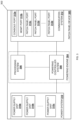
- FIG. 3 is a schematic view illustrating an embodiment of a patch panel device that may be included in the networked system of FIG. 2 .
- FIG. 4 is a flow chart illustrating an embodiment of a method for powering devices via a patch panel.
- FIG. 5 A is a schematic view illustrating an embodiment of the networked system of FIG. 2 operating during the method of FIG. 4 .
- FIG. 5 B is a schematic view illustrating an embodiment of the patch panel device of FIG. 3 operating during the method of FIG. 4 .
- FIG. 5 C is a schematic view illustrating an embodiment of the networked system of FIG. 2 operating during the method of FIG. 4 .
- FIG. 5 D is a schematic view illustrating an embodiment of the patch panel device of FIG. 3 operating during the method of FIG. 4 .
- FIG. 5 E is a schematic view illustrating an embodiment of the networked system of FIG. 2 operating during the method of FIG. 4 .
- FIG. 5 F is a schematic view illustrating an embodiment of the patch panel device of FIG. 3 operating during the method of FIG. 4 .
- FIG. 5 G is a schematic view illustrating an embodiment of the networked system of FIG. 2 operating during the method of FIG. 4 .
- FIG. 5 H is a schematic view illustrating an embodiment of the patch panel device of FIG. 3 operating during the method of FIG. 4 .
- FIG. 5 I is a schematic view illustrating an embodiment of the networked system of FIG. 2 operating during the method of FIG. 4 .
- FIG. 5 J is a schematic view illustrating an embodiment of the patch panel device of FIG. 3 operating during the method of FIG. 4 .
- an information handling system may include any instrumentality or aggregate of instrumentalities operable to compute, calculate, determine, classify, process, transmit, receive, retrieve, originate, switch, store, display, communicate, manifest, detect, record, reproduce, handle, or utilize any form of information, intelligence, or data for business, scientific, control, or other purposes.
- an information handling system may be a personal computer (e.g., desktop or laptop), tablet computer, mobile device (e.g., personal digital assistant (PDA) or smart phone), server (e.g., blade server or rack server), a network storage device, or any other suitable device and may vary in size, shape, performance, functionality, and price.
- the information handling system may include random access memory (RAM), one or more processing resources such as a central processing unit (CPU) or hardware or software control logic, ROM, and/or other types of nonvolatile memory. Additional components of the information handling system may include one or more disk drives, one or more network ports for communicating with external devices as well as various input and output (I/O) devices, such as a keyboard, a mouse, touchscreen and/or a video display. The information handling system may also include one or more buses operable to transmit communications between the various hardware components.
- RAM random access memory
- processing resources such as a central processing unit (CPU) or hardware or software control logic
- ROM read-only memory
- Additional components of the information handling system may include one or more disk drives, one or more network ports for communicating with external devices as well as various input and output (I/O) devices, such as a keyboard, a mouse, touchscreen and/or a video display.
- I/O input and output
- the information handling system may also include one or more buses operable to transmit communications between the various
- IHS 100 includes a processor 102 , which is connected to a bus 104 .
- Bus 104 serves as a connection between processor 102 and other components of IHS 100 .
- An input device 106 is coupled to processor 102 to provide input to processor 102 .
- Examples of input devices may include keyboards, touchscreens, pointing devices such as mouses, trackballs, and trackpads, and/or a variety of other input devices known in the art.
- Programs and data are stored on a mass storage device 108 , which is coupled to processor 102 . Examples of mass storage devices may include hard discs, optical disks, magneto-optical discs, solid-state storage devices, and/or a variety of other mass storage devices known in the art.
- IHS 100 further includes a display 110 , which is coupled to processor 102 by a video controller 112 .
- a system memory 114 is coupled to processor 102 to provide the processor with fast storage to facilitate execution of computer programs by processor 102 .
- Examples of system memory may include random access memory (RAM) devices such as dynamic RAM (DRAM), synchronous DRAM (SDRAM), solid state memory devices, and/or a variety of other memory devices known in the art.
- RAM random access memory
- DRAM dynamic RAM
- SDRAM synchronous DRAM
- solid state memory devices solid state memory devices
- a chassis 116 houses some or all of the components of IHS 100 . It should be understood that other buses and intermediate circuits can be deployed between the components described above and processor 102 to facilitate interconnection between the components and the processor 102 .
- the networked system 200 includes a plurality of switch devices 202 a , 202 b , and up to 202 c .
- the switch devices 202 a - 202 c may be provided by the IHS 100 discussed above with reference to FIG.
- IHS 100 may include some or all of the components of the IHS 100 , and in some of the specific examples below are provided by co-packaged switch devices, copper-port switch devices, hybrid power/fiber port switch devices, and/or other switch devices having powering capabilities (e.g., Power over Ethernet (PoE)) capabilities), while in others of the specific examples below are provided by fiber port switch devices, copper-port switch devices, co-packaged switch devices, and/or other switch devices without powering capabilities.
- PoE Power over Ethernet
- switch devices provided in the networked system 200 may include other networking devices and/or other computing devices that may be configured to operate similarly as the switch devices 202 a - 202 c discussed below.
- the networked system 200 may also include a patch panel device 204 that is coupled to each of the plurality of switch devices 202 a - 202 c via respective ports on the patch panel device 204 , discussed in further detail below.
- the patch panel device 204 may be provided by the IHS 100 discussed above with reference to FIG. 1 , and/or may include some or all of the components of the IHS 100 .
- the patch panel device 204 may include a variety of conventional patch panel features including an array of ports (e.g., switch device ports/networking device ports in the examples below) that may each be utilized to connect respective switch devices 202 a - 202 c to each other and/or to the powered devices discussed below.
- ports e.g., switch device ports/networking device ports in the examples below
- datacenters may include conventional patch panel devices (e.g., similar to the patch panel device 204 described herein but without the powering patch panel functionality discussed below) to which switch devices are connected (e.g., via cabling) in order to shorten the length of cabling needed to connect those switch devices, simplify switch device connection troubleshooting, and/or provide other patch panel benefits known in the art.
- conventional patch panel devices e.g., similar to the patch panel device 204 described herein but without the powering patch panel functionality discussed below
- switch devices e.g., via cabling
- the patch panel device 204 may differ from any of the switch devices 202 a - 202 c based on that patch panel device 204 providing basic physical layer connectivity between two or more patch panel ports on the patch panel device 204 (e.g., to connect two or more devices), while not performing many (or all) of the layer 2 (L2) and layer 3 (L3) protocol operations that are conventionally performed by the switch devices 202 a - 202 c .
- L2 layer 2
- L3 layer 3
- the patch panel device 204 is not limited in power capabilities like the switch devices 202 a - 202 c (i.e., due to their form-factor constraints that limit the switch device chassis to, for example, 1 U or 2 U rack heights), and thus may support larger power systems and may allow for power system expansions (e.g., the chassis of each switch device 202 a - 202 c may be limited to two power supply units, while the chassis of the patch panel device 204 may be configured to house eight or more power supply units).
- conventional switch devices are currently limited to between 1 Gigabit Ethernet (GbE) and 10 GbE data transmission speeds, while the patch panel device 204 may be configured to support data transmission speeds higher than 10 GbE.
- any one of the switch devices 202 a - 202 c may be limited to 48 switch ports (particular when those switch devices 202 a - 202 c are configured to power connected device via a PoE protocol), while the patch panel device 204 may be configured with 128 patch panel ports, 256 patch panel ports, 512 patch panel ports, or more in future implementations, as patch panel device designs may be modular and allow the addition of patch panel ports up to any desired amount.
- the patch panel device 204 and the switch devices 202 a - 202 c (as well as conventional switch devices) have been described, one of skill in the art in possession of the present disclosure will appreciate that other differences exist between panel devices and switch devices as well.
- the networked system 200 also includes a plurality of powered devices 206 a , 206 b , and up to 206 c .
- the powered devices 206 a - 206 c may be provided by the IHS 100 discussed above with reference to FIG. 1 , and/or may include some or all of the components of the IHS 100 , and in specific examples may include powered camera devices, powered badge/card readers, powered Voice over Internet Protocol (VoIP) phone devices, powered lighting devices, and/or other powered devices known in the art.
- VoIP Voice over Internet Protocol
- powered devices provided in the networked system 200 may include other powered devices that may be configured to operate similarly as the powered devices 206 a - 206 b discussed below.
- the networked system 200 may also include a power source 208 that is coupled to the patch panel device 204 , and that may be provided by Alternating Current (AC) power outlets, power storage systems (e.g., battery systems), power generating equipment, and/or any of a variety of power sources including any power source components/elements known in the art.
- AC Alternating Current
- the patch panel device 300 may provide the patch panel device 204 discussed above with reference to FIG. 2 .
- the patch panel device 300 may be provided by the IHS 100 discussed above with reference to FIG. 1 and/or may include some or all of the components of the IHS 100 .
- the patch panel device 300 includes a chassis 302 that houses the components of the patch panel device 300 , only some of which are illustrated and discussed below.
- the chassis 302 may house at least one processing device (not illustrated, but which may include the processor 102 discussed above with reference to FIG. 1 ) and at least one memory device (not illustrated, but which may include one or more of the memory 114 discussed above with reference to FIG.
- a powering engine 304 that is configured to perform the functionality of the powering engines and/or patch panel devices discussed below.
- the powering engine 304 includes a processing system 306 that may include one or more Network Processing Units (NPUs) (e.g., network processor device(s) that provide a subset of the processing device(s) in the powering engine 304 ) and corresponding NPU memory (e.g., network memory device(s) that provide a subset of the memory device(s) in the powering engine 304 ), and a power controller system 308 that may include one or more Power over Ethernet (PoE) controllers (e.g., PoE controller processor device(s) that provide a subset of the processing device(s) in the powering engine 304 and PoE controller memory device(s) that provide a subset of the memory device(s) in the powering engine 304 ).
- NPUs Network Processing Units
- PoE controller system 308 may include one or more Power over Ethernet (PoE) controllers (e.g., PoE controller processor device(s) that provide a subset of the processing device(s) in the powering
- any particular NPU/NPU memory combination may be capable of performing NPU operations for a subset of patch panel ports on the patch panel device 300
- any particular PoE controller may be capable of performing PoE operations for a subset of patch panel ports on the patch panel device 300
- the number of NPUs/NPU memory (or other processors/memory) and PoE controllers (or other powering controllers) included in the processing system 306 and powering controller system 308 , respectively, may depend on the number of patch panel ports on the patch panel device 300 .
- the processing system may include physical layer (PHY) devices (e.g., Ethernet chips) that are configured to perform the layer 1 (L1) negotiation operations discussed below, and in specific examples a respective PHY device may be included in or otherwise provided with each NPU (e.g., as part of each NPU Application Specific Integrated Circuit (ASIC)).
- PHY physical layer
- the powering controller system e.g., PoE controllers
- PHY devices e.g., Ethernet chips
- processing system and powering controller system e.g., including PHY devices
- functionality e.g., L1 negotiation operations
- the chassis 302 may also house a power system 310 that is coupled to the powering controller system 308 in the powering engine 304 and that includes a plurality of power supply units 310 a , 310 b , and up to 310 c , and while not illustrated, may include any of a variety of other power components that would be apparent to one of skill in the art in possession of the present disclosure.
- the chassis 302 of the patch panel device 204 / 300 is not constrained by form-factor limitations that are generally present for the switch devices 202 a - 202 c discussed above with reference to FIG.
- the number of power supply units included in the power system 310 of the chassis 302 may selected based on the number of patch panel ports for which a maximum powering level will be provided.
- the number of power supply units in the power system 310 will typically exceed the number of power supply units that are typically provided in conventional switch devices (e.g., a maximum of two power supply units for many conventional switch devices vs. eight or more power supply units for the patch panel device 300 ) and that typically limit the number of ports on conventional switch devices through which a maximum powering level may be provided.
- the chassis 302 may also house a communication system 308 that is coupled to the processing system 306 and the powering controller system 308 in the powering engine 304 (e.g., via a coupling between the communication system 308 and the processor devices) and that may be provided by a Network Interface Controller (NIC), wireless communication systems (e.g., BLUETOOTH®, Near Field Communication (NFC) components, WiFi components, cellular components, etc.), and/or any other communication components that would be apparent to one of skill in the art in possession of the present disclosure.
- NIC Network Interface Controller
- wireless communication systems e.g., BLUETOOTH®, Near Field Communication (NFC) components, WiFi components, cellular components, etc.
- the communication system 312 includes a console port 312 a , a management (“MGMT”) port 312 b , and a plurality of patch panel ports 312 c , 312 d , and up to 312 e .
- the powering patch panel system of the present disclosure allows the patch panel device 300 to include 128 patch panel ports, 256 patch panel ports, 512 patch panel ports, or more while providing maximum powering levels to each of those patch panel ports, as distinguished from conventional switch devices that can typically provide maximum powering levels to approximately 12 switch ports.
- a first subset of the patch panel ports 312 c - 312 e may be optical-fiber-based ports (e.g., Multi-fiber Push-On (MPO) ports) connected via respective optical-fiber-based cables (e.g., MPO cables) to respective switch devices 202 a - 202 c
- a second subset of the patch panel ports 312 c - 312 e may be hybrid conductive-material/optical-fiber-based ports connected via respective hybrid conductive-material/optical-fiber-based cables to respective powered devices 206 a - 206 c .
- At least one of the inventors of the present disclosure has described the hybrid conductive-material/optical-fiber-based ports and/or hybrid conductive-material/optical-fiber-based cables referenced above at least in U.S. Pat. No. 11,012,156, issued on May 18, 2021; U.S. Pat. No. 11,011,288, issued on May 18, 2021; U.S. patent application Ser. No. 17/168,408, filed on Feb. 5, 2021; and U.S. patent application Ser. No. 17/203,930, filed on Mar. 17, 2021; the disclosures of which are incorporated herein by reference in their entirety.
- a first subset of the patch panel ports 312 c - 312 e may be optical-fiber-based ports (e.g., MPO ports) connected via respective optical-fiber-based cables (e.g., MPO cables) to respective switch devices 202 a - 202 c
- a second subset of the patch panel ports 312 c - 312 e may be conductive-material-based ports (e.g., Ethernet ports) connected via respective conductive-material-based cables (e.g., Ethernet cables) to respective powered devices 206 a - 206 c .
- a first subset of the patch panel ports 312 c - 312 e may be conductive-material-based ports (e.g., Ethernet ports) connected via respective conductive-material-based cables (e.g., Ethernet cables) to respective switch devices 202 a - 202 c
- a second subset of the patch panel ports 312 c - 312 e may be conductive-material-based ports (e.g., Ethernet ports) connected via respective conductive-material-based cables (e.g., Ethernet ports) to respective powered devices 206 a - 206 c .
- patch panel devices may include a variety of components and/or component configurations for providing conventional patch panel device functionality, as well as the functionality discussed below, while remaining within the scope of the present disclosure as well.
- a powering patch panel system may include a patch panel device coupled to a power source, and including a first port that is coupled to a networking device via a first cable and a second port that is coupled to the powered device via a second cable.
- the patch panel device receives data that is directed to the powered device from the networking device through the first port and via the first cable, and receives power from the power source.
- the patch panel device then transmits both the data and a subset of the power through the second port and via the second cable to the powered device.
- a conventional switch device may transmit data destined for a powered device to the patch panel device up to the limits of a data cable (e.g., approximately 300 meters for conventional Ethernet cables), and the patch panel device may transmit data along with power to that powered device up to the limits of a power/data cable (e.g., approximately 100 meters for conventional Ethernet cables), thus extending PoE distance limits of 100 meters to 400 meters.
- the patch panel device may have its power system configured to ensure that 128 ports, 256 ports, 512 ports, or more ports on the patch panel device are each capable of providing maximum powering levels to their respective connected powered devices, eliminating the need for additional switch devices in a datacenter due to switch device form-factor limitations that prevent their associated power systems from providing maximum powering levels to all of their switch ports.
- the method 400 begins at block 402 where a patch panel device negotiates a subset of power that will be provided to a powered device.
- the powering controller system 308 may communicate via any of its patch panel ports 312 c - 312 e that are connected to a powered device 206 a - 206 c in order to perform powering negotiation operations with that powering device. For example, with reference to FIG.
- the powering controller system 308 may perform powering negotiations operations 500 that include communicating via the patch panel port 312 c that is connected to the powered device 206 a in order to negotiate a subset of power that will be provided to the powered device 206 a , and one of skill in the art in possession of the present disclosure will appreciate how similar negotiation operations may be performed with any of the other powered devices 206 b - 206 c while remaining within the scope of the present disclosure as well.
- powering negotiations operations may be enabled, at least in part, by configuring the patch panel ports 312 c - 312 e that are connected to a powered device 206 a - 206 c to perform conventional default PoE auto-negotiation operations, and then performing any of a variety of conventional default PoE auto-negotiation operations that one of skill in the art in possession of the present disclosure would recognize as defining a subset of power that will be provided by the patch panel device 204 / 300 to the powered device 206 a via the patch panel port 312 c.
- the processing system 306 may communicate via any of its patch panel ports 312 c - 312 e that are connected to a switch device 202 a - 202 c in order to perform data communication negotiation operations (e.g., Ethernet negotiations) with that switch device.
- data communication negotiation operations e.g., Ethernet negotiations
- the processing system 306 may perform data communication negotiations operations 502 that include communicating via the patch panel port 312 d that is connected to the switch device 202 a in order to negotiate data communication parameters (e.g., Ethernet parameters) for data communications that will be exchanged with the switch device 202 a , and one of skill in the art in possession of the present disclosure will appreciate how similar negotiation operations may be performed with any of the other switch devices 202 b - 202 c while remaining within the scope of the present disclosure as well.
- data communication parameters e.g., Ethernet parameters
- data communication negotiations operations may be enabled, at least in part, by configuring the patch panel ports 312 c - 312 e that are connected to a powered device 206 a - 206 c to perform conventional default Ethernet auto-negotiation operations, and then performing any of a variety of conventional default Ethernet auto-negotiation operations that one of skill in the art in possession of the present disclosure would recognize as defining the Ethernet parameters for data communications that will be provided by the patch panel device 204 / 300 to the switch device 202 a via the patch panel port 312 cd.
- a network administrator or other user of the networked system may manually define data communications between the patch panel device 204 / 300 and any switch device 202 a - 202 c , and/or manually define power/data communications between the patch panel device 204 / 300 and any powered device 206 a - 206 c .
- an administrator or other user may connect to the console port 312 a or the management port 312 b of the patch panel device 204 / 300 in order to set data communication parameters (e.g., Ethernet parameters) for data communications with any of the switch devices 202 a / 202 c , or define a subset of power that may be provided to any of the powered devices 206 a - 206 c .
- data communication parameters e.g., Ethernet parameters
- the patch panel device 300 may run a Linux kernel (e.g., a Suse Linux kernel, a Debian Linux kernel, an Ubuntu Linux kernel, or other Linus Enterprise Server variants known in the art) that allows the processing system 306 (e.g., an Ethernet ASIC/NPU device), the powering controller system 308 (e.g., a PoE controller), and/or one or more default settings to be configured.
- a Linux kernel e.g., a Suse Linux kernel, a Debian Linux kernel, an Ubuntu Linux kernel, or other Linus Enterprise Server variants known in the art
- the processing system 306 e.g., an Ethernet ASIC/NPU device
- the powering controller system 308 e.g., a PoE controller
- streamlined kernels may allow “plug-and-play” connectivity with the patch panel device 204 / 300 with minimal management requirements, and may be accessed via serial control ports (e.g., the console port 312 a ) or out-of-band management ports (e.g., the management port 312 b ) via standard accessibility interfaces and via industry standards.
- serial control ports e.g., the console port 312 a
- out-of-band management ports e.g., the management port 312 b
- the method 400 then proceeds to block 404 where the patch panel device receives data directed to the powered device from a networking device through a first port on the patch panel device and via a first cable connected to the first port.
- the patch panel device 204 may receive data from any of the switch devices 202 a - 202 c that is directed to any of the powered devices 206 a - 206 c .
- the switch devices 202 a - 202 c may be any of the switch devices 202 a - 202 c that is directed to any of the powered devices 206 a - 206 c .
- the processing system 206 in the patch panel device 204 may perform data receiving operations 504 that include receiving data from the switch device 202 a via the patch panel port 312 d that is connected to the switch device 202 a and, as discussed in further detail below, that data may be directed to the powered device 206 a.
- the data received from the switch device 202 a at block 404 may be transmitted via a conventional Ethernet cable that is up to 300 meters long (e.g., up to the limits of that data transmission capabilities of conventional Ethernet cables) and that is connected to both the switch device 202 a and the patch panel ports 312 d .
- data may be received from any switch device 202 a - 202 c via an optical-fiber-based cable, thus increasing the distance which that data may be transmitted to over 300 meters.
- the method 400 then proceeds to block 406 where the patch panel device receives power from a power source.
- the patch panel device 204 / 300 may perform power receiving operations 506 that include receiving power from the power source 208 and, as illustrated in FIG. 5 H , the powering controller system 308 may then perform power accessing operations 508 that include accessing the power received by the power system 310 in the patch panel device 204 / 300 as part of the powering receiving operations 506 (as well as the power provisioning operations described below).
- the power received as part of the power receiving operations 506 may translate into a relatively large power provisioning capacity in the patch panel device 204 / 300 due to the relatively large number of power supply units 310 a - 310 c that the chassis 302 is capable of housing, which may be configured to allow the powering controller system 308 to power each of the patch panel ports 312 c - 312 e up to a maximum powering level (e.g., a class 4 universal PoE (uPoE) powering level) even when the patch panel device 204 / 300 includes 128 patch panel ports, 256 patch panel ports, 512 patch panel ports, or more.
- a maximum powering level e.g., a class 4 universal PoE (uPoE) powering level
- the method 400 then proceeds to block 408 where the patch panel device transmits both the data and the subset of the power through a second port on the patch panel device and via a second cable connected to the second port and the powered device.
- the patch panel device 204 may transmit any data received at block 404 along with a subset of the power received at block 406 to any of the powered devices 206 a - 206 c .
- the powered devices 206 a - 206 c For example, with reference to FIGS.
- the processing system 306 and the powering controller system 308 in the patch panel device 204 / 300 may perform power/data transmission operations 510 in order to transmit the data received from the switch device 202 a along with a subset of the power received from the power source 208 that is based on the negotiations performed at block 402 to the powered device 206 a.
- the data and the subset of the power may be transmitted to the powered device 206 a via an Ethernet cable (or other conductive-material-based cable) that is up to 100 meters long (e.g., up to the limits of the power transmission capabilities of conventional Ethernet cables) and that is connected to both the powered device 206 a and the patch panel port 312 c .
- an Ethernet cable or other conductive-material-based cable that is up to 100 meters long (e.g., up to the limits of the power transmission capabilities of conventional Ethernet cables) and that is connected to both the powered device 206 a and the patch panel port 312 c .
- the patch panel device 204 / 300 may transmit data and a subset of the power received from the power source 208 to each of the powered devices 206 a - 206 c , with the distance between any of the switch devices 202 a - 202 b and any of the powered devices 206 a - 206 b extended to up to 400 meters when powering a powered device using conventional Ethernet cabling (i.e., as compared to 100 meters when a conventional PoE switch device is connected to a powered device via conventional Ethernet cabling).
- data may be transmitted to any powering device 206 a - 206 c via an optical-fiber-based cable or an optical-fiber-based portion of a hybrid conductive-material-based/optical fiber-based cable while remaining within the scope of the present disclosure as well.
- one or more of the switch devices 202 a - 202 c may be configured to power powered devices (e.g., those switch devices may be PoE capable).
- the ports on that switch device that are connected to the patch panel ports 312 c - 312 e on the patch panel device 204 may have their powering capabilities (e.g., PoE functionality) disabled.
- a powering patch panel system may include a patch panel device coupled to a power source, and including a first port that is coupled to a networking device via a first cable and a second port that is coupled to the powered device via a second cable.
- the patch panel device receives data that is directed to the powered device from the networking device through the first port and via the first cable, and receives power from the power source.
- the patch panel device transmits both the data and a subset of the power through the second port and via the second cable to the powered device.
- a conventional switch device may transmit data destined for a powered device to the patch panel device up to the limits of a data cable (e.g., approximately 300 meters for conventional Ethernet cables), and the patch panel device may transmit data along with power to that powered device up to the limits of a power/data cable (e.g., approximately 100 meters for conventional Ethernet cables), thus extending PoE distance limits of 100 meters to 400 meters.
- the patch panel device may have its power system configured to ensure that 128 ports, 256 ports, 512 ports, or more, are capable of providing maximum powering levels to their respective connected powered devices, eliminating the need for additional switch devices in a datacenter due to switch device form-factor limitations that prevent their associated power systems from providing maximum powering levels to all of their switch ports
Abstract
Description
Claims (20)
Priority Applications (1)
| Application Number | Priority Date | Filing Date | Title |
|---|---|---|---|
| US17/361,512 US11822406B2 (en) | 2021-06-29 | 2021-06-29 | Powering patch panel system |
Applications Claiming Priority (1)
| Application Number | Priority Date | Filing Date | Title |
|---|---|---|---|
| US17/361,512 US11822406B2 (en) | 2021-06-29 | 2021-06-29 | Powering patch panel system |
Publications (2)
| Publication Number | Publication Date |
|---|---|
| US20220413577A1 US20220413577A1 (en) | 2022-12-29 |
| US11822406B2 true US11822406B2 (en) | 2023-11-21 |
Family
ID=84543113
Family Applications (1)
| Application Number | Title | Priority Date | Filing Date |
|---|---|---|---|
| US17/361,512 Active 2041-10-22 US11822406B2 (en) | 2021-06-29 | 2021-06-29 | Powering patch panel system |
Country Status (1)
| Country | Link |
|---|---|
| US (1) | US11822406B2 (en) |
Citations (7)
| Publication number | Priority date | Publication date | Assignee | Title |
|---|---|---|---|---|
| US20050136989A1 (en) * | 2003-12-12 | 2005-06-23 | Dove Daniel J. | Method and system for distributing power to networked devices |
| US20060063509A1 (en) * | 1999-01-12 | 2006-03-23 | David Pincu | System for providing power over Ethernet through a patch panel |
| US20080168283A1 (en) * | 2007-01-05 | 2008-07-10 | Avaya Technology Llc | Apparatus and methods for managing Power distribution over Ethernet |
| US20130339760A1 (en) * | 2012-06-15 | 2013-12-19 | Cisco Technology, Inc. | Intelligent midspan poe injector |
| US20150078740A1 (en) * | 2013-09-19 | 2015-03-19 | RADIUS UNIVERSAL, A Limited Liability Company of the State of New York | Fiber optic communications network |
| US20160020911A1 (en) * | 2013-09-19 | 2016-01-21 | RADIUS UNIVERSAL, A Limited Liability Company of the State of New York | Fiber optic communications and power network |
| US20170117971A1 (en) * | 2013-09-19 | 2017-04-27 | Radius Universal Llc | Fiber optic communications and power network |
-
2021
- 2021-06-29 US US17/361,512 patent/US11822406B2/en active Active
Patent Citations (7)
| Publication number | Priority date | Publication date | Assignee | Title |
|---|---|---|---|---|
| US20060063509A1 (en) * | 1999-01-12 | 2006-03-23 | David Pincu | System for providing power over Ethernet through a patch panel |
| US20050136989A1 (en) * | 2003-12-12 | 2005-06-23 | Dove Daniel J. | Method and system for distributing power to networked devices |
| US20080168283A1 (en) * | 2007-01-05 | 2008-07-10 | Avaya Technology Llc | Apparatus and methods for managing Power distribution over Ethernet |
| US20130339760A1 (en) * | 2012-06-15 | 2013-12-19 | Cisco Technology, Inc. | Intelligent midspan poe injector |
| US20150078740A1 (en) * | 2013-09-19 | 2015-03-19 | RADIUS UNIVERSAL, A Limited Liability Company of the State of New York | Fiber optic communications network |
| US20160020911A1 (en) * | 2013-09-19 | 2016-01-21 | RADIUS UNIVERSAL, A Limited Liability Company of the State of New York | Fiber optic communications and power network |
| US20170117971A1 (en) * | 2013-09-19 | 2017-04-27 | Radius Universal Llc | Fiber optic communications and power network |
Also Published As
| Publication number | Publication date |
|---|---|
| US20220413577A1 (en) | 2022-12-29 |
Similar Documents
| Publication | Publication Date | Title |
|---|---|---|
| TWI540417B (en) | Power allocation controller | |
| US9940143B2 (en) | Using peripheral component interconnect express vendor-defined message (PCIe-VDM) and inter-integrated circuit (I2C) transport for network communications | |
| US11336318B2 (en) | Transceiver device port configuration and monitoring system | |
| US8386686B2 (en) | Cloud computer | |
| US20130102237A1 (en) | Server, server component and method for controlling fan speed | |
| US10146022B1 (en) | PoE electrical/optical data signal converter system | |
| US9531594B2 (en) | Self-configuring port system | |
| US9690343B2 (en) | Power distribution system | |
| US11005945B2 (en) | Profiled wireless docking system | |
| US9804980B2 (en) | System management through direct communication between system management controllers | |
| US8745423B2 (en) | System for combined input output module and zero power optical disk drive with advanced integration and power | |
| US20080056285A1 (en) | Method and system for connecting wireless personal area network (WPAN) devices through display systems | |
| US10203737B2 (en) | Power distribution between multiple powering devices and powered device(s) | |
| US11822406B2 (en) | Powering patch panel system | |
| US11494156B1 (en) | Cable connection information display system | |
| US11599149B2 (en) | Docking station supporting power inputs from a display | |
| CN109039955A (en) | A kind of storage system based on optical-fibre channel | |
| US11088963B2 (en) | Automatic aggregated networking device backup link configuration system | |
| US11061838B1 (en) | System and method for graphics processing unit management infrastructure for real time data collection | |
| US11314302B2 (en) | Power/data transmission breakout system | |
| US11435801B1 (en) | Powering co-packaged networking system | |
| US8020009B2 (en) | Dynamic performance management of network interface | |
| US11301014B2 (en) | Power/data transmission extender system | |
| US10938636B2 (en) | Apparatus and method for physical layer transceiver configuration | |
| US20240136852A1 (en) | Wireless charger as a garaged/detachable unit |
Legal Events
| Date | Code | Title | Description |
|---|---|---|---|
| AS | Assignment |
Owner name: DELL PRODUCTS L.P., TEXAS Free format text: ASSIGNMENT OF ASSIGNORS INTEREST;ASSIGNORS:BEARD, NEAL;RATHINASAMY, SHREE;REEL/FRAME:056700/0680 Effective date: 20210624 |
|
| FEPP | Fee payment procedure |
Free format text: ENTITY STATUS SET TO UNDISCOUNTED (ORIGINAL EVENT CODE: BIG.); ENTITY STATUS OF PATENT OWNER: LARGE ENTITY |
|
| AS | Assignment |
Owner name: CREDIT SUISSE AG, CAYMAN ISLANDS BRANCH, NORTH CAROLINA Free format text: SECURITY AGREEMENT;ASSIGNORS:DELL PRODUCTS, L.P.;EMC IP HOLDING COMPANY LLC;REEL/FRAME:057682/0830 Effective date: 20211001 |
|
| AS | Assignment |
Owner name: THE BANK OF NEW YORK MELLON TRUST COMPANY, N.A., AS NOTES COLLATERAL AGENT, TEXAS Free format text: SECURITY INTEREST;ASSIGNORS:DELL PRODUCTS L.P.;EMC IP HOLDING COMPANY LLC;REEL/FRAME:057931/0392 Effective date: 20210908 Owner name: THE BANK OF NEW YORK MELLON TRUST COMPANY, N.A., AS NOTES COLLATERAL AGENT, TEXAS Free format text: SECURITY INTEREST;ASSIGNORS:DELL PRODUCTS L.P.;EMC IP HOLDING COMPANY LLC;REEL/FRAME:058014/0560 Effective date: 20210908 Owner name: THE BANK OF NEW YORK MELLON TRUST COMPANY, N.A., AS NOTES COLLATERAL AGENT, TEXAS Free format text: SECURITY INTEREST;ASSIGNORS:DELL PRODUCTS L.P.;EMC IP HOLDING COMPANY LLC;REEL/FRAME:057758/0286 Effective date: 20210908 |
|
| AS | Assignment |
Owner name: EMC IP HOLDING COMPANY LLC, TEXAS Free format text: RELEASE OF SECURITY INTEREST IN PATENTS PREVIOUSLY RECORDED AT REEL/FRAME (057758/0286);ASSIGNOR:THE BANK OF NEW YORK MELLON TRUST COMPANY, N.A., AS NOTES COLLATERAL AGENT;REEL/FRAME:061654/0064 Effective date: 20220329 Owner name: DELL PRODUCTS L.P., TEXAS Free format text: RELEASE OF SECURITY INTEREST IN PATENTS PREVIOUSLY RECORDED AT REEL/FRAME (057758/0286);ASSIGNOR:THE BANK OF NEW YORK MELLON TRUST COMPANY, N.A., AS NOTES COLLATERAL AGENT;REEL/FRAME:061654/0064 Effective date: 20220329 Owner name: EMC IP HOLDING COMPANY LLC, TEXAS Free format text: RELEASE OF SECURITY INTEREST IN PATENTS PREVIOUSLY RECORDED AT REEL/FRAME (058014/0560);ASSIGNOR:THE BANK OF NEW YORK MELLON TRUST COMPANY, N.A., AS NOTES COLLATERAL AGENT;REEL/FRAME:062022/0473 Effective date: 20220329 Owner name: DELL PRODUCTS L.P., TEXAS Free format text: RELEASE OF SECURITY INTEREST IN PATENTS PREVIOUSLY RECORDED AT REEL/FRAME (058014/0560);ASSIGNOR:THE BANK OF NEW YORK MELLON TRUST COMPANY, N.A., AS NOTES COLLATERAL AGENT;REEL/FRAME:062022/0473 Effective date: 20220329 Owner name: EMC IP HOLDING COMPANY LLC, TEXAS Free format text: RELEASE OF SECURITY INTEREST IN PATENTS PREVIOUSLY RECORDED AT REEL/FRAME (057931/0392);ASSIGNOR:THE BANK OF NEW YORK MELLON TRUST COMPANY, N.A., AS NOTES COLLATERAL AGENT;REEL/FRAME:062022/0382 Effective date: 20220329 Owner name: DELL PRODUCTS L.P., TEXAS Free format text: RELEASE OF SECURITY INTEREST IN PATENTS PREVIOUSLY RECORDED AT REEL/FRAME (057931/0392);ASSIGNOR:THE BANK OF NEW YORK MELLON TRUST COMPANY, N.A., AS NOTES COLLATERAL AGENT;REEL/FRAME:062022/0382 Effective date: 20220329 |
|
| STPP | Information on status: patent application and granting procedure in general |
Free format text: NON FINAL ACTION MAILED |
|
| STPP | Information on status: patent application and granting procedure in general |
Free format text: DOCKETED NEW CASE - READY FOR EXAMINATION |
|
| STPP | Information on status: patent application and granting procedure in general |
Free format text: NOTICE OF ALLOWANCE MAILED -- APPLICATION RECEIVED IN OFFICE OF PUBLICATIONS |
|
| STPP | Information on status: patent application and granting procedure in general |
Free format text: PUBLICATIONS -- ISSUE FEE PAYMENT RECEIVED |
|
| STPP | Information on status: patent application and granting procedure in general |
Free format text: PUBLICATIONS -- ISSUE FEE PAYMENT VERIFIED |
|
| STCF | Information on status: patent grant |
Free format text: PATENTED CASE |