US1181908A - Valve-dressing device. - Google Patents
Valve-dressing device. Download PDFInfo
- Publication number
- US1181908A US1181908A US6571215A US6571215A US1181908A US 1181908 A US1181908 A US 1181908A US 6571215 A US6571215 A US 6571215A US 6571215 A US6571215 A US 6571215A US 1181908 A US1181908 A US 1181908A
- Authority
- US
- United States
- Prior art keywords
- valve
- standard
- frame
- support
- pin
- Prior art date
- Legal status (The legal status is an assumption and is not a legal conclusion. Google has not performed a legal analysis and makes no representation as to the accuracy of the status listed.)
- Expired - Lifetime
Links
Images

Classifications
-
- B—PERFORMING OPERATIONS; TRANSPORTING
- B23—MACHINE TOOLS; METAL-WORKING NOT OTHERWISE PROVIDED FOR
- B23C—MILLING
- B23C3/00—Milling particular work; Special milling operations; Machines therefor
- B23C3/02—Milling surfaces of revolution
- B23C3/05—Finishing valves or valve seats
-
- Y—GENERAL TAGGING OF NEW TECHNOLOGICAL DEVELOPMENTS; GENERAL TAGGING OF CROSS-SECTIONAL TECHNOLOGIES SPANNING OVER SEVERAL SECTIONS OF THE IPC; TECHNICAL SUBJECTS COVERED BY FORMER USPC CROSS-REFERENCE ART COLLECTIONS [XRACs] AND DIGESTS
- Y10—TECHNICAL SUBJECTS COVERED BY FORMER USPC
- Y10T—TECHNICAL SUBJECTS COVERED BY FORMER US CLASSIFICATION
- Y10T409/00—Gear cutting, milling, or planing
- Y10T409/30—Milling
- Y10T409/306216—Randomly manipulated, work supported, or work following device
-
- Y—GENERAL TAGGING OF NEW TECHNOLOGICAL DEVELOPMENTS; GENERAL TAGGING OF CROSS-SECTIONAL TECHNOLOGIES SPANNING OVER SEVERAL SECTIONS OF THE IPC; TECHNICAL SUBJECTS COVERED BY FORMER USPC CROSS-REFERENCE ART COLLECTIONS [XRACs] AND DIGESTS
- Y10—TECHNICAL SUBJECTS COVERED BY FORMER USPC
- Y10T—TECHNICAL SUBJECTS COVERED BY FORMER US CLASSIFICATION
- Y10T82/00—Turning
- Y10T82/29—Attachment for cutting a valve
Definitions
- This invention relates to a device for dressing automobile valves and their seats, the operations being successive, and performed by substantially the same mech- A perfect it is therefore obtained with less labor and time and more certainty than if the dressing was limited to the seat or valve alone.
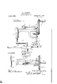
- FIG. 1 is a side elevation, a part being broken away.
- FIG. 2 is a plan view.
- Fig. 3 is a detail sectional view, a valve being shown in dressing position.
- Fig. 4: is a front elevation.
- Fig. ⁇ 5 is aV vplan view, partly broken out, of a slidable support.
- Fig. 6 is a side elevation of a su port holder.
- Fig. 7 is a perspective view o a le support.
- Fig. 8 is an elevation of a modified form of valve engaging pin.
- my device I In constructing my device I provide a suitable frame 1 adjustably mounted on an angled standard 2, which in turn is carried by a suitable clamp 3 adapted to secure the standard to an engine base or casing.
- the frame l is provided with a vertically arranged sleeve 4L which receives the upper vertical portion of the standard 2 so that the entire frame 1 may be swung to left or right or raised or lowered with respect to the part to which the clamp 8 is secured.
- On the frame 1 are bearings 5k for a horizontal shaft 6 on the forward end of which is a bevel gear wheel 7, having a handle 8.
- the lower end of the shaft 9 is recessed and working in said recess is a pin 11, said pin being slotted as shown at 12 and a pin 13 extends through said slot, thereby preventing the pin turning with respect to the shaft 9, but permitting vertical movement.
- a spring 14 is Specification of Letters Patent.
- the pin has awlower reduced threaded portion 15 which carries a plate 16, and said plate carries two pins 17 adapted to engage the usual small sockets formed in valves.
- a channeled plate 18 and a support 19 is slidably mounted in said channelway.
- This support as shown in detail in Fig. 5 is longitudinally slotted as at 20, the standard passing through said slot and the support is secured to said standard by a suitable set screw 32, se as to lock the support in adjusted position.
- a block 21 carries, at an angle to the perpendicular, a screw or threaded pin 22, and said block is slotted as at 23, so that the block may be adjustably secured, as by a set screw, to one side of the support 19, and adjacent its forward end.
- rlhis block forms a holder for a file support, shown in detail in Fig. 7.
- the rite support consists of a block 24 grooved at 25 to receive the file, 27, also secured in place by a set screw, and the block has adjacent one corner Va lug 26 provided with a j suitable smooth bore 26EL adapted to engage the screw or pin 222.
- the support 19 has a countersunk opening 28.
- valves are not provided ⁇ with the sockets above mentioned but are provided with a central slot similar to a screw-head.
- I employ a pin 29, having alengitudinal groove 39 and a wedgeshaped point 31. Where the valve is-provided only with the one slot this pin is substituted for the pin 11 and plate 16.
- the frame l is then brought into position, being lowered on the standard 2 to give the desired pressure on the valve, the pins 17 or, if used, the pin 29, engaging and turning the valve.
- the spring 14e acts as a cushion and applies the proper tpressure, regulated by adjustment of the frame l vertically, and by turning the gear Wheel 7 the shaft 9, the part carried thereby and the valve Will be turned, the abrasive device being in engagement With that portion of the valve to be dressed.
- llVhen the necessary Ydressing has been accomplished, the valve is removed, a suitable paste (forming no part ofthe present invention) is placed on the valve seat, and the valve reseated.
- the valve is then again engaged by the pins Y17 or pin 29, and this time turned forward and backward thus dressing the-seat to exactly fit the valve.
- the device is then removed by loosening the clamp 3.
- What I claim is l. ln a devicel of the kind described, a standard, a channeled plate secured transversely on the standard, a. valve support slidably carried on said plate, andk having a countersunk opening adapted to receive a valve stem, a frame adjustably carried by the standard, a vertical shaft carried by the frame, andspring pressed means carried by the loiver endof said shaft and adapted to engage the valve, together with means carried by the frame for rotating said shaft and'valve engaging means.
- a standard means for clamping the standard to an engine base, a plate carried yby the standard, a valve support slidablyY carried by said plate, and having I a countersunk opening adjacent one end, aavasher adapted to lit in said countersunk portion and to receive a valve stem, an adjustable holder carried by the side of the valve support and adjacent said opening, a supporting block carried kby said holder, an abrasive-material carried Lby said block, and means supported from said standard for rotating the valve.
- a valve dressing device means for supporting a valve to be dressed adjacent an abrasive material, a vertically movable frame, a depending shaft carried by the frame and having its loiver end recessed, valve engaging means seated in said recess, a spring arranged in said recess and bearing downwardly on said valve engaging means, the pressure of the spring being regulated by adjustment of the frame, and means carried by the frame for rotating said shaft.
- an angled standard a frame having a vertical sleeve at one end, said sleeve fitting on the upper vertical portion of the standard, a longitudinally grooved plate secured transversely on the lovver vertical portion of the standard, a longitudinally slotted, valvesupporting member slidably held in the groove of the plate, the standard passing loosely through the slot of said member, means for locking said member in adjusting position to the standard, means for securing the frame in adjusted position to the standard, adjustable means carried by a side of the valve supporting member for holding an ab asive material, a shaft mounted on the frame, a drive gear thereon, a second shaft carried by the frame at right angles to the first mentioned shaft, a gear thereon meshing with the first mentioned gear, and spring pressedl valve engaging means slidably keyed in the whichever portion of the second mentioned shaft.
- valve engagingand rotating means carried thereby, comprising a hollow rotatable shaft and a slotted spring-pressed pin Working in and projecting from said shaft, a horizontally slidable valve support, said support having a countersunk opening, interchangeable Washers adapted t0 rest in said opening and receive a valve stem, and adj ustablo means carried by said support and adapted to hold an Aabrasive material at an angle to and against one side ofv said valve.
Description
W. C. MCDONALD.
VALVEIDRESSING DEVICE.
APPLlcATloN FILED 1150.8. 1915.
Patent-ed May 2, 1916.
2 SHEETS-SHEET I.
@Dwi/humo w. @.MCDONALp. VALVE DRESSING DEVICE.
APPLICATION FILED DEC.8, |915.
Patnted May 2, 1916.
2 SHEETS-SHEET 2.
WILLIAM C. MGDONALD, F COLUMBUS, GEORGIA, ASSIGNGR OF ONE-THIRD T0 BRICK S. MILLER .AND ONE-THIRD `T0 W. CECIL NEILL, BOTH OF COLUMBUS, GEORGIA.
VALVE-DRESSING DEVICE.
` To all whom it may concern anism.
Be it known that I, WVILLIAM C. MODON- ALD, a citizen of the United States, residing at Columbus, in the county of Muscogeeand State of Georgia, have invented certain new and useful Improvements in Valve-Dressing Devices, of which the following is a specification.
This invention relates to a device for dressing automobile valves and their seats, the operations being successive, and performed by substantially the same mech- A perfect it is therefore obtained with less labor and time and more certainty than if the dressing was limited to the seat or valve alone. Y
The invention consists in the novel features of construction hereinafter described, pointed out in the claims and shown in the accompanying drawings in which Figure l is a side elevation, a part being broken away. Fig. 2 is a plan view. Fig. 3 is a detail sectional view, a valve being shown in dressing position. Fig. 4: is a front elevation. Fig.` 5 is aV vplan view, partly broken out, of a slidable support. Fig. 6 is a side elevation of a su port holder. Fig. 7 is a perspective view o a le support. Fig. 8 is an elevation of a modified form of valve engaging pin.
In constructing my device I provide a suitable frame 1 adjustably mounted on an angled standard 2, which in turn is carried by a suitable clamp 3 adapted to secure the standard to an engine base or casing. At
` its rear end the frame l is provided with a vertically arranged sleeve 4L which receives the upper vertical portion of the standard 2 so that the entire frame 1 may be swung to left or right or raised or lowered with respect to the part to which the clamp 8 is secured. On the frame 1 are bearings 5k for a horizontal shaft 6 on the forward end of which is a bevel gear wheel 7, having a handle 8. Journaled in the frame 1 and an arm 1a of the frame, is a vertical shaft 9 on which is fixed a bevel gear wheel 10 meshing with the gear 7. Y
As shown in Fig. 3 the lower end of the shaft 9 is recessed and working in said recess is a pin 11, said pin being slotted as shown at 12 and a pin 13 extends through said slot, thereby preventing the pin turning with respect to the shaft 9, but permitting vertical movement. A spring 14 is Specification of Letters Patent.
Patented May 2, 1916.
Application led December 8, 1915. Serial No. 65,712.
seated in the upper end of the recess and bears onwthe upper end of the pin 11. The pin has awlower reduced threaded portion 15 which carries a plate 16, and said plate carries two pins 17 adapted to engage the usual small sockets formed in valves.
Locked on the lower vertical portion of the angled standard 2 is a channeled plate 18 and a support 19 is slidably mounted in said channelway. This support as shown in detail in Fig. 5 is longitudinally slotted as at 20, the standard passing through said slot and the support is secured to said standard by a suitable set screw 32, se as to lock the support in adjusted position.
A block 21 carries, at an angle to the perpendicular, a screw or threaded pin 22, and said block is slotted as at 23, so that the block may be adjustably secured, as by a set screw, to one side of the support 19, and adjacent its forward end. rlhis block forms a holder for a file support, shown in detail in Fig. 7. The iile support consists of a block 24 grooved at 25 to receive the file, 27, also secured in place by a set screw, and the block has adjacent one corner Va lug 26 provided with a j suitable smooth bore 26EL adapted to engage the screw or pin 222. At its .forward end the support 19 has a countersunk opening 28. In actual practice I make this opening fg of an inch in diameter with the countersunk portion 1 inch in diameter and Yth of an inch deep. A washer 28"L is placed in the countersunk portion and the opening in the washer corresponds to the size of the stem B of a valve A. It is understood that several of these washers are employed with openings of varying sizes to fit different valve stems.
Some valves are not provided `with the sockets above mentioned but are provided with a central slot similar to a screw-head. To hold such valves I employ a pin 29, having alengitudinal groove 39 and a wedgeshaped point 31. Where the valve is-provided only with the one slot this pin is substituted for the pin 11 and plate 16.
To dress an automobile valve and its sea-t the operation is as follows :-The machine is suitably clamped to the engine casing by the clamp 3 and the valve to be dressed is re-` moved. The support 19 is then adjusted so that the opening 28 will be over the valve seat, and fastened in place by the set screw 32. A. washer 28a of the proper size is placed in the countersunk portion of the openino' 28 and the valve stem B inserted therein. A suitable filing or other abrasive instrument is placed in the file support, and said support and its holder properly adjusted to the right angle for the Work to be done. The frame l is then brought into position, being lowered on the standard 2 to give the desired pressure on the valve, the pins 17 or, if used, the pin 29, engaging and turning the valve. The spring 14e acts as a cushion and applies the proper tpressure, regulated by adjustment of the frame l vertically, and by turning the gear Wheel 7 the shaft 9, the part carried thereby and the valve Will be turned, the abrasive device being in engagement With that portion of the valve to be dressed. llVhen the necessary Ydressing has been accomplished, the valve is removed, a suitable paste (forming no part ofthe present invention) is placed on the valve seat, and the valve reseated. The valve is then again engaged by the pins Y17 or pin 29, and this time turned forward and backward thus dressing the-seat to exactly fit the valve. When the seat has been properly dressed the device is then removed by loosening the clamp 3.
What I claim is l. ln a devicel of the kind described, a standard, a channeled plate secured transversely on the standard, a. valve support slidably carried on said plate, andk having a countersunk opening adapted to receive a valve stem, a frame adjustably carried by the standard, a vertical shaft carried by the frame, andspring pressed means carried by the loiver endof said shaft and adapted to engage the valve, together with means carried by the frame for rotating said shaft and'valve engaging means. Y
2. In a valve dressing device, a standard, means for clamping the standard to an engine base, a plate carried yby the standard, a valve support slidablyY carried by said plate, and having I a countersunk opening adjacent one end, aavasher adapted to lit in said countersunk portion and to receive a valve stem, an adjustable holder carried by the side of the valve support and adjacent said opening, a supporting block carried kby said holder, an abrasive-material carried Lby said block, and means supported from said standard for rotating the valve.
3. In a valve dressing device, means for supporting a valve to be dressed adjacent an abrasive material, a vertically movable frame, a depending shaft carried by the frame and having its loiver end recessed, valve engaging means seated in said recess, a spring arranged in said recess and bearing downwardly on said valve engaging means, the pressure of the spring being regulated by adjustment of the frame, and means carried by the frame for rotating said shaft.
4. In a device of the kind described, an angled standard, a frame having a vertical sleeve at one end, said sleeve fitting on the upper vertical portion of the standard, a longitudinally grooved plate secured transversely on the lovver vertical portion of the standard, a longitudinally slotted, valvesupporting member slidably held in the groove of the plate, the standard passing loosely through the slot of said member, means for locking said member in adjusting position to the standard, means for securing the frame in adjusted position to the standard, adjustable means carried by a side of the valve supporting member for holding an ab asive material, a shaft mounted on the frame, a drive gear thereon, a second shaft carried by the frame at right angles to the first mentioned shaft, a gear thereon meshing with the first mentioned gear, and spring pressedl valve engaging means slidably keyed in the louer portion of the second mentioned shaft.
5. In a device of the kind described, a
vertically adjustable frame, valve engagingand rotating means carried thereby, comprising a hollow rotatable shaft and a slotted spring-pressed pin Working in and projecting from said shaft, a horizontally slidable valve support, said support having a countersunk opening, interchangeable Washers adapted t0 rest in said opening and receive a valve stem, and adj ustablo means carried by said support and adapted to hold an Aabrasive material at an angle to and against one side ofv said valve.
ln testimony whereof ailix my signature in the presence of tivo Witnesses.
VILLAM C. MGDONAL'D.
1Witnesses YV. N. JON-Es, M. K. BAGLEY.
Copies ofthis patent may be obtained for ve cents each, by addressing the Commissioner of Patents.
v' Washington, D. C.
Priority Applications (1)
| Application Number | Priority Date | Filing Date | Title |
|---|---|---|---|
| US6571215A US1181908A (en) | 1915-12-08 | 1915-12-08 | Valve-dressing device. |
Applications Claiming Priority (1)
| Application Number | Priority Date | Filing Date | Title |
|---|---|---|---|
| US6571215A US1181908A (en) | 1915-12-08 | 1915-12-08 | Valve-dressing device. |
Publications (1)
| Publication Number | Publication Date |
|---|---|
| US1181908A true US1181908A (en) | 1916-05-02 |
Family
ID=3249882
Family Applications (1)
| Application Number | Title | Priority Date | Filing Date |
|---|---|---|---|
| US6571215A Expired - Lifetime US1181908A (en) | 1915-12-08 | 1915-12-08 | Valve-dressing device. |
Country Status (1)
| Country | Link |
|---|---|
| US (1) | US1181908A (en) |
Cited By (2)
| Publication number | Priority date | Publication date | Assignee | Title |
|---|---|---|---|---|
| US2618105A (en) * | 1950-04-20 | 1952-11-18 | Arthur H Anderson | Valve grinder |
| US3648416A (en) * | 1970-05-22 | 1972-03-14 | Jack Rogers | Portable valve facer |
-
1915
- 1915-12-08 US US6571215A patent/US1181908A/en not_active Expired - Lifetime
Cited By (2)
| Publication number | Priority date | Publication date | Assignee | Title |
|---|---|---|---|---|
| US2618105A (en) * | 1950-04-20 | 1952-11-18 | Arthur H Anderson | Valve grinder |
| US3648416A (en) * | 1970-05-22 | 1972-03-14 | Jack Rogers | Portable valve facer |
Similar Documents
| Publication | Publication Date | Title |
|---|---|---|
| US1181908A (en) | Valve-dressing device. | |
| US526571A (en) | Henry j | |
| US1385519A (en) | Cutting-tool holder | |
| US1216600A (en) | Milling attachment for lathes. | |
| US1282022A (en) | Lens-slotting machine. | |
| US2683385A (en) | Sharpening device with angular and longitudinal adjustments | |
| US548298A (en) | Island | |
| US614092A (en) | F fotx | |
| US483042A (en) | Tool-rest for grinding-machines | |
| US1197785A (en) | Edging-machine. | |
| US1044254A (en) | Valve-truing tool. | |
| US348497A (en) | Tool-holder for grinding | |
| US759865A (en) | Sandpapering-machine. | |
| US407577A (en) | Twist drills | |
| US381775A (en) | Saw sharpening machine | |
| US1030256A (en) | Razor-honing machine. | |
| US697853A (en) | Work-rest for grinding-machines. | |
| US373203A (en) | Assigm | |
| US760151A (en) | Clamp. | |
| US1144277A (en) | Wheel dresser and truer. | |
| US631562A (en) | Diamond-polishing dop. | |
| US697852A (en) | Work-rest for grinding-machines. | |
| US897408A (en) | Abrading-machine. | |
| US497313A (en) | Machine for grinding cutters | |
| US557981A (en) | John edward evard |