US11815134B2 - Anti-rattle feature for clutch plate - Google Patents

Anti-rattle feature for clutch plate Download PDF

Info

Publication number
US11815134B2
US11815134B2 US17/671,007 US202217671007A US11815134B2 US 11815134 B2 US11815134 B2 US 11815134B2 US 202217671007 A US202217671007 A US 202217671007A US 11815134 B2 US11815134 B2 US 11815134B2
Authority
US
United States
Prior art keywords
plate
primary inertia
clutch plate
drive assembly
clutch
Prior art date
Legal status (The legal status is an assumption and is not a legal conclusion. Google has not performed a legal analysis and makes no representation as to the accuracy of the status listed.)
Active, expires
Application number
US17/671,007
Other versions
US20230258235A1 (en
Inventor
Nicholas Wurst
Current Assignee (The listed assignees may be inaccurate. Google has not performed a legal analysis and makes no representation or warranty as to the accuracy of the list.)
Schaeffler Technologies AG and Co KG
Original Assignee
Schaeffler Technologies AG and Co KG
Priority date (The priority date is an assumption and is not a legal conclusion. Google has not performed a legal analysis and makes no representation as to the accuracy of the date listed.)
Filing date
Publication date
Application filed by Schaeffler Technologies AG and Co KG filed Critical Schaeffler Technologies AG and Co KG
Priority to US17/671,007 priority Critical patent/US11815134B2/en
Assigned to Schaeffler Technologies AG & Co. KG reassignment Schaeffler Technologies AG & Co. KG ASSIGNMENT OF ASSIGNORS INTEREST (SEE DOCUMENT FOR DETAILS). Assignors: WURST, NICHOLAS
Publication of US20230258235A1 publication Critical patent/US20230258235A1/en
Application granted granted Critical
Publication of US11815134B2 publication Critical patent/US11815134B2/en
Active legal-status Critical Current
Adjusted expiration legal-status Critical

Links

Images

Classifications

    • FMECHANICAL ENGINEERING; LIGHTING; HEATING; WEAPONS; BLASTING
    • F16ENGINEERING ELEMENTS AND UNITS; GENERAL MEASURES FOR PRODUCING AND MAINTAINING EFFECTIVE FUNCTIONING OF MACHINES OR INSTALLATIONS; THERMAL INSULATION IN GENERAL
    • F16DCOUPLINGS FOR TRANSMITTING ROTATION; CLUTCHES; BRAKES
    • F16D13/00Friction clutches
    • F16D13/22Friction clutches with axially-movable clutching members
    • F16D13/38Friction clutches with axially-movable clutching members with flat clutching surfaces, e.g. discs
    • F16D13/385Friction clutches with axially-movable clutching members with flat clutching surfaces, e.g. discs double clutches, i.e. comprising two friction disc mounted on one driven shaft
    • FMECHANICAL ENGINEERING; LIGHTING; HEATING; WEAPONS; BLASTING
    • F16ENGINEERING ELEMENTS AND UNITS; GENERAL MEASURES FOR PRODUCING AND MAINTAINING EFFECTIVE FUNCTIONING OF MACHINES OR INSTALLATIONS; THERMAL INSULATION IN GENERAL
    • F16DCOUPLINGS FOR TRANSMITTING ROTATION; CLUTCHES; BRAKES
    • F16D13/00Friction clutches
    • F16D13/58Details
    • F16D13/60Clutching elements
    • F16D13/64Clutch-plates; Clutch-lamellae
    • F16D13/68Attachments of plates or lamellae to their supports
    • FMECHANICAL ENGINEERING; LIGHTING; HEATING; WEAPONS; BLASTING
    • F16ENGINEERING ELEMENTS AND UNITS; GENERAL MEASURES FOR PRODUCING AND MAINTAINING EFFECTIVE FUNCTIONING OF MACHINES OR INSTALLATIONS; THERMAL INSULATION IN GENERAL
    • F16DCOUPLINGS FOR TRANSMITTING ROTATION; CLUTCHES; BRAKES
    • F16D13/00Friction clutches
    • F16D13/58Details
    • F16D13/70Pressure members, e.g. pressure plates, for clutch-plates or lamellae; Guiding arrangements for pressure members
    • FMECHANICAL ENGINEERING; LIGHTING; HEATING; WEAPONS; BLASTING
    • F16ENGINEERING ELEMENTS AND UNITS; GENERAL MEASURES FOR PRODUCING AND MAINTAINING EFFECTIVE FUNCTIONING OF MACHINES OR INSTALLATIONS; THERMAL INSULATION IN GENERAL
    • F16DCOUPLINGS FOR TRANSMITTING ROTATION; CLUTCHES; BRAKES
    • F16D13/00Friction clutches
    • F16D13/58Details
    • F16D13/60Clutching elements
    • F16D13/64Clutch-plates; Clutch-lamellae
    • F16D13/68Attachments of plates or lamellae to their supports
    • F16D13/683Attachments of plates or lamellae to their supports for clutches with multiple lamellae
    • FMECHANICAL ENGINEERING; LIGHTING; HEATING; WEAPONS; BLASTING
    • F16ENGINEERING ELEMENTS AND UNITS; GENERAL MEASURES FOR PRODUCING AND MAINTAINING EFFECTIVE FUNCTIONING OF MACHINES OR INSTALLATIONS; THERMAL INSULATION IN GENERAL
    • F16DCOUPLINGS FOR TRANSMITTING ROTATION; CLUTCHES; BRAKES
    • F16D2300/00Special features for couplings or clutches
    • F16D2300/22Vibration damping

Definitions

  • the present disclosure relates to an anti-rattle feature for a clutch plate.
  • Clutch plate and drive assemblies are well known.
  • Clutch plates generally have a driving connection with a primary inertia plate or member.
  • the primary inertia plate is connected to the crankshaft and therefore receives driving input from the engine.
  • the primary inertia plate Due to engine speed fluctuations and general operating conditions, the primary inertia plate generally experiences rattling, vibrations, or other movement that can be caused by piston motion in the engine. This vibration or rattling is then transmitted to the clutch plate due to the connection between the primary inertia plate and the clutch plate.
  • a drive assembly including a primary inertia plate and clutch plate is disclosed herein.
  • the primary inertia plate is configured to be rotationally driven via a crankshaft.
  • the clutch plate includes a body with a rotational axis (X).
  • the clutch plate is configured to be rotationally driven by the primary inertia plate.
  • the clutch plate includes at least one imbalance feature such that a center of gravity of the clutch plate is positioned away from the rotational axis (X).
  • the imbalance feature can be embodied as a modification in geometry of the clutch plate that alters its center of gravity.
  • the primary inertia plate can include at least one pocket
  • the clutch plate can include at least one spline configured to be received within the at least one pocket.
  • Various types of driving or lash connections can be provided between the primary inertia plate and the clutch plate.
  • the primary inertia plate can include at least one pocket, and the clutch plate can include at least one tab configured to be received within the at least one pocket.
  • the primary inertia plate can further include at least one flange within the at least one pocket, and the at least one flange is configured to engage with at least one tab.
  • the at least one pocket can include a plurality of pockets, and the at least one tab can include a plurality of tabs.
  • the at least one imbalance feature can include at least one protrusion projecting from the body.
  • the at least one protrusion can be formed integrally with the body.
  • the at least one protrusion can project radially outward from the body, or can project in another direction.
  • the at least one imbalance feature comprises at least one void in the body.
  • the void can be formed as a through hole having a fully formed perimeter by the body of the clutch plate.
  • a clutch assembly can also be provided that includes the clutch plate, at least one friction plate, and a piston plate.
  • the clutch plate is configured to be selectively rotationally driven by the primary inertia plate via either a direct friction connection or a lash connection.
  • FIG. 1 is cross-sectional side view a drive assembly according to one aspect.
  • FIG. 2 is a top perspective view of an interface between a clutch plate and a primary inertia plate from FIG. 1 .
  • FIG. 3 A is a magnified view of a pocket-tab interface between the clutch plate and the primary inertia plate from FIG. 1 .
  • FIG. 3 B is a magnified view of another pocket-tab interface.
  • FIG. 4 is a front view along an axial direction of the clutch plate of FIG. 1 .
  • FIG. 5 is a schematic illustration of a clutch plate and a primary inertia plate interface according to one aspect.
  • a reference to a list of items that are cited as “at least one of a, b, or c” means any single one of the items a, b, or c, or combinations thereof.
  • the terminology includes the words specifically noted above, derivatives thereof and words of similar import.
  • a drive assembly 1 is generally disclosed herein.
  • the drive assembly 1 includes a primary inertia plate 10 configured to be rotationally driven via a crankshaft (not shown).
  • a clutch plate 20 is also provided that includes a body 22 with a rotational axis (X).
  • the clutch plate 20 is configured to be rotationally driven by the primary inertia plate 10 .
  • the clutch plate 20 is part of a clutch assembly 30 that also includes at least one friction plate 32 a , 32 b , and a piston plate 34 .
  • the clutch plate 20 is configured to be driven by the primary inertia plate 10 directly via a friction connection, or can be configured to be driven via a lash connection, as described in more detail herein.
  • the piston plate 34 is axially displaced to engage and compress with the friction plates 32 a , 32 b , and the clutch plate 20 , such that these components are rotationally locked with the primary inertia plate 10 .
  • the clutch assembly 30 In the lash connection drive mode, the clutch assembly 30 is disengaged (i.e. open), and the clutch plate 20 is driven by the primary inertia plate 10 via a lash or other connection (such as a tab-pocket connection or other male-female connection with a gap).
  • a lash or other connection such as a tab-pocket connection or other male-female connection with a gap.
  • the primary inertia plate 110 can include at least one pocket 112
  • the clutch plate 120 can include at least one spline 124 configured to be received within the at least one pocket 112 , as shown in FIG. 5 .
  • the spline connection between the primary inertia plate 110 and the clutch plate 120 can be configured as a toothed engagement, in one aspect.
  • Various other types of non-circular splined or toothed connections can be provided between the primary inertia plate 110 and the clutch plate 120 .
  • the primary inertia plate 10 can include at least one pocket 12
  • the clutch plate 20 can include at least one tab 24 configured to be received within the at least one pocket 12 as shown in FIGS. 1 - 3 A .
  • the at least one pocket 12 can include a plurality of pockets 12
  • the at least one tab 24 can include a plurality of tabs 24 , in one aspect.
  • the plurality of pockets 12 are defined along a radially outer region of the primary inertia plate 10 and the plurality of tabs 24 are defined along a radially outer region of the clutch plate 20 .
  • the plurality of tabs 24 are generally formed as axially extending flanges, in one aspect.
  • the quantity of pockets and tabs can vary depending on the particular requirements of a design. Additionally, the geometry or profile of the pockets and tabs can vary.
  • two of the tabs 24 ′ are relatively larger than the other tabs 24 .
  • This increase in size which correlates to an increase in mass, causes the center of gravity to be shifted.
  • the tabs 24 ′ are illustrated as being wider in FIG. 2 , one of ordinary skill in the art would understand that the length of these tabs could also be increased relative to the other tabs, which also would cause a shift in the center of gravity and a resulting imbalance force.
  • the primary inertia plate 10 can further include at least one flange 14 within the at least one pocket 12 , and the at least one flange 14 can be configured to engage with at least one tab 24 .
  • Flanges can be provided on one or both of the circumferential or peripheral areas of the pockets 12 and can be configured to provide engagement elements or abutments for engagement with the tabs 24 .
  • the tabs 24 can engage directly against a perimeter surface of the pockets 12 , and the flanges can be omitted.
  • the clutch plate 20 includes at least one imbalance feature such that a center of gravity (COG) of the clutch plate 20 is positioned away from the rotational axis (X).
  • COG center of gravity
  • FIG. 5 the imbalance feature comprises at least one protrusion 26 a , 26 b extending from or otherwise formed with the body 22 , as shown in FIG. 4 .
  • the at least one protrusion 26 a , 26 b can be formed integrally with body 22 , in one aspect.
  • the at least one protrusion 26 a , 26 b projects radially outward from the body 22 , in one aspect.
  • the protrusion 26 a , 26 b extends only in the radial direction.
  • the protrusion 26 a , 26 b can be defined in a circumferential area between tabs 24 .
  • at least two protrusions 26 a , 26 b can be provided.
  • the protrusions 26 a , 26 b have a predetermined mass and based on this increase of mass in the body 22 , the COG is displaced in a direction towards the protrusions 26 a , 26 b relative to the rotational axis (X).
  • the protrusion can alternatively project in a radial inward direction, axial direction, or any other direction.
  • the imbalance feature can comprise at least one void 126 in the body 122 , as shown in FIG. 5 .
  • the void 126 can be formed as a through opening, indentation, or recess on the clutch plate 120 .
  • the void 126 can be defined on the clutch plate 120 in an area or location away from the portion of the clutch plate 120 that engages with the primary inertia plate 110 .
  • the COG is displaced relative to the rotation axis (X) in a direction away from the void 126 .
  • the void 126 can be defined in an area radially inward from the interface portion of the clutch plate configured to engage with the primary inertia plate.
  • the imbalance features disclosed herein can be formed integrally with the clutch plate, which simplifies assembly due to reduction in complexity or installing additional damping or rattle-preventing elements.
  • the imbalance features disclosed herein generally causes the center of gravity to shift or be displaced away from the rotational axis (X) of the clutch plate.
  • a centrifugal force is generated on the clutch plate that causes the clutch plate to bias or fling radially outward while rotating or spinning.
  • This centrifugal force causes a contact force to be generated between the interface elements (i.e. tabs, pockets, splines, flanges, etc.) formed on the clutch plate and primary inertia plate.
  • this centrifugal force can be determined or designed to overcome the force generated due to engine fluctuations, which are otherwise transmitted from the crankshaft to the primary inertia plate and the clutch plate.
  • the centrifugal force generated due to the imbalance feature can be configured to prevent rattling of the clutch plate by overcoming the vibrational or rattling forces imparted by the crankshaft.

Landscapes

  • Engineering & Computer Science (AREA)
  • General Engineering & Computer Science (AREA)
  • Mechanical Engineering (AREA)
  • Hydraulic Clutches, Magnetic Clutches, Fluid Clutches, And Fluid Joints (AREA)

Abstract

A drive assembly including a primary inertia plate and clutch. The primary inertia plate is configured to be rotationally driven via a crankshaft. The clutch plate includes a body with a rotational axis (X). The clutch plate is configured to be rotationally driven by the primary inertia plate. The clutch plate includes at least one imbalance feature such that a center of gravity of the clutch plate is positioned away from the rotational axis (X). The imbalance feature generates a centrifugal force that counteracts or prevents rattling from being imparted to the clutch plate via engine vibrations through the primary inertia plate.

Description

FIELD OF INVENTION
The present disclosure relates to an anti-rattle feature for a clutch plate.
BACKGROUND
Clutch plate and drive assemblies are well known. Clutch plates generally have a driving connection with a primary inertia plate or member. The primary inertia plate is connected to the crankshaft and therefore receives driving input from the engine.
Due to engine speed fluctuations and general operating conditions, the primary inertia plate generally experiences rattling, vibrations, or other movement that can be caused by piston motion in the engine. This vibration or rattling is then transmitted to the clutch plate due to the connection between the primary inertia plate and the clutch plate.
Accordingly, it would be desirable to provide an improved configuration for a clutch plate that avoids noise, vibration, harshness (NVH).
SUMMARY
A drive assembly including a primary inertia plate and clutch plate is disclosed herein. The primary inertia plate is configured to be rotationally driven via a crankshaft. The clutch plate includes a body with a rotational axis (X). The clutch plate is configured to be rotationally driven by the primary inertia plate. The clutch plate includes at least one imbalance feature such that a center of gravity of the clutch plate is positioned away from the rotational axis (X). The imbalance feature can be embodied as a modification in geometry of the clutch plate that alters its center of gravity.
The primary inertia plate can include at least one pocket, and the clutch plate can include at least one spline configured to be received within the at least one pocket. Various types of driving or lash connections can be provided between the primary inertia plate and the clutch plate.
The primary inertia plate can include at least one pocket, and the clutch plate can include at least one tab configured to be received within the at least one pocket.
The primary inertia plate can further include at least one flange within the at least one pocket, and the at least one flange is configured to engage with at least one tab. The at least one pocket can include a plurality of pockets, and the at least one tab can include a plurality of tabs.
The at least one imbalance feature can include at least one protrusion projecting from the body.
The at least one protrusion can be formed integrally with the body. The at least one protrusion can project radially outward from the body, or can project in another direction.
In one aspect, the at least one imbalance feature comprises at least one void in the body. The void can be formed as a through hole having a fully formed perimeter by the body of the clutch plate.
A clutch assembly can also be provided that includes the clutch plate, at least one friction plate, and a piston plate. The clutch plate is configured to be selectively rotationally driven by the primary inertia plate via either a direct friction connection or a lash connection.
Additional embodiments are disclosed herein.
BRIEF DESCRIPTION OF THE DRAWINGS
The foregoing Summary and the following Detailed Description will be better understood when read in conjunction with the appended drawings, which illustrate a preferred embodiment of the disclosure. In the drawings:
FIG. 1 is cross-sectional side view a drive assembly according to one aspect.
FIG. 2 is a top perspective view of an interface between a clutch plate and a primary inertia plate from FIG. 1 .
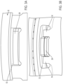
FIG. 3A is a magnified view of a pocket-tab interface between the clutch plate and the primary inertia plate from FIG. 1 .
FIG. 3B is a magnified view of another pocket-tab interface.
FIG. 4 is a front view along an axial direction of the clutch plate of FIG. 1 .
FIG. 5 is a schematic illustration of a clutch plate and a primary inertia plate interface according to one aspect.
DETAILED DESCRIPTION OF THE PREFERRED EMBODIMENTS
Certain terminology is used in the following description for convenience only and is not limiting. “Axially” refers to a direction along an axis (X) of an assembly. “Radially” refers to a direction inward and outward from the axis (X) of the assembly. “Circumferentially” refers to a direction extending along a curve or circumference of a respective element relative to the axis (X) of the assembly.
A reference to a list of items that are cited as “at least one of a, b, or c” (where a, b, and c represent the items being listed) means any single one of the items a, b, or c, or combinations thereof. The terminology includes the words specifically noted above, derivatives thereof and words of similar import.
As shown in FIG. 1 , a drive assembly 1 is generally disclosed herein. The drive assembly 1 includes a primary inertia plate 10 configured to be rotationally driven via a crankshaft (not shown). A clutch plate 20 is also provided that includes a body 22 with a rotational axis (X).
The clutch plate 20 is configured to be rotationally driven by the primary inertia plate 10. The clutch plate 20 is part of a clutch assembly 30 that also includes at least one friction plate 32 a, 32 b, and a piston plate 34. In one aspect, the clutch plate 20 is configured to be driven by the primary inertia plate 10 directly via a friction connection, or can be configured to be driven via a lash connection, as described in more detail herein. To be driven via a direct friction connection, the piston plate 34 is axially displaced to engage and compress with the friction plates 32 a, 32 b, and the clutch plate 20, such that these components are rotationally locked with the primary inertia plate 10. In the lash connection drive mode, the clutch assembly 30 is disengaged (i.e. open), and the clutch plate 20 is driven by the primary inertia plate 10 via a lash or other connection (such as a tab-pocket connection or other male-female connection with a gap). One of ordinary skill in the art would understand that various types of driving connections could be provided for the clutch plate 20 and the primary inertia plate 10.
The primary inertia plate 110 can include at least one pocket 112, and the clutch plate 120 can include at least one spline 124 configured to be received within the at least one pocket 112, as shown in FIG. 5 . The spline connection between the primary inertia plate 110 and the clutch plate 120 can be configured as a toothed engagement, in one aspect. Various other types of non-circular splined or toothed connections can be provided between the primary inertia plate 110 and the clutch plate 120.
The primary inertia plate 10 can include at least one pocket 12, and the clutch plate 20 can include at least one tab 24 configured to be received within the at least one pocket 12 as shown in FIGS. 1-3A. The at least one pocket 12 can include a plurality of pockets 12, and the at least one tab 24 can include a plurality of tabs 24, in one aspect. In one aspect, the plurality of pockets 12 are defined along a radially outer region of the primary inertia plate 10 and the plurality of tabs 24 are defined along a radially outer region of the clutch plate 20. The plurality of tabs 24 are generally formed as axially extending flanges, in one aspect. One of ordinary skill in the art would understand that the quantity of pockets and tabs can vary depending on the particular requirements of a design. Additionally, the geometry or profile of the pockets and tabs can vary.
As shown in FIG. 2 , two of the tabs 24′ are relatively larger than the other tabs 24. This increase in size, which correlates to an increase in mass, causes the center of gravity to be shifted. While the tabs 24′ are illustrated as being wider in FIG. 2 , one of ordinary skill in the art would understand that the length of these tabs could also be increased relative to the other tabs, which also would cause a shift in the center of gravity and a resulting imbalance force.
As shown in FIG. 3B, the primary inertia plate 10 can further include at least one flange 14 within the at least one pocket 12, and the at least one flange 14 can be configured to engage with at least one tab 24. Flanges can be provided on one or both of the circumferential or peripheral areas of the pockets 12 and can be configured to provide engagement elements or abutments for engagement with the tabs 24. In another aspect, the tabs 24 can engage directly against a perimeter surface of the pockets 12, and the flanges can be omitted.
The clutch plate 20 includes at least one imbalance feature such that a center of gravity (COG) of the clutch plate 20 is positioned away from the rotational axis (X). This aspect is shown schematically in FIG. 5 . One of ordinary skill in the art would recognize from this disclosure that adjusting the position of the COG of the clutch plate 20 can be achieved in a variety of manners. For example, in one aspect, the imbalance feature comprises at least one protrusion 26 a, 26 b extending from or otherwise formed with the body 22, as shown in FIG. 4 . The at least one protrusion 26 a, 26 b can be formed integrally with body 22, in one aspect. The at least one protrusion 26 a, 26 b projects radially outward from the body 22, in one aspect. In one aspect, the protrusion 26 a, 26 b extends only in the radial direction. The protrusion 26 a, 26 b can be defined in a circumferential area between tabs 24. As shown in FIG. 4 , at least two protrusions 26 a, 26 b can be provided. The protrusions 26 a, 26 b have a predetermined mass and based on this increase of mass in the body 22, the COG is displaced in a direction towards the protrusions 26 a, 26 b relative to the rotational axis (X). One of ordinary skill in the art would understand that the protrusion can alternatively project in a radial inward direction, axial direction, or any other direction.
The imbalance feature can comprise at least one void 126 in the body 122, as shown in FIG. 5 . The void 126 can be formed as a through opening, indentation, or recess on the clutch plate 120. The void 126 can be defined on the clutch plate 120 in an area or location away from the portion of the clutch plate 120 that engages with the primary inertia plate 110. As shown in FIG. 5 , the COG is displaced relative to the rotation axis (X) in a direction away from the void 126. The void 126 can be defined in an area radially inward from the interface portion of the clutch plate configured to engage with the primary inertia plate.
The imbalance features disclosed herein can be formed integrally with the clutch plate, which simplifies assembly due to reduction in complexity or installing additional damping or rattle-preventing elements.
The imbalance features disclosed herein generally causes the center of gravity to shift or be displaced away from the rotational axis (X) of the clutch plate. By shifting the center of gravity, a centrifugal force is generated on the clutch plate that causes the clutch plate to bias or fling radially outward while rotating or spinning. This centrifugal force causes a contact force to be generated between the interface elements (i.e. tabs, pockets, splines, flanges, etc.) formed on the clutch plate and primary inertia plate. Based on the characteristics of the imbalance feature, this centrifugal force can be determined or designed to overcome the force generated due to engine fluctuations, which are otherwise transmitted from the crankshaft to the primary inertia plate and the clutch plate. The centrifugal force generated due to the imbalance feature can be configured to prevent rattling of the clutch plate by overcoming the vibrational or rattling forces imparted by the crankshaft.
Various relationships and equations can be provided for determining the appropriate balancing force to counteract the rattling force imparted by the primary inertia plate to the clutch plate. These relationships and equations generally are based on variables that analyze the requisite force necessary to counteract the rattle force, and may include adjusting the mass of the clutch plate in various ways, including but not limited to adjusting the size of the tabs, adding protrusions, removing material, etc.
Although tabs or splines are shown on the clutch plate and pockets are shown on the primary inertia plate, one of ordinary skill in the art would understand this arrangement can be reversed.
Having thus described the present disclosure in detail, it is to be appreciated and will be apparent to those skilled in the art that many physical changes, only a few of which are exemplified in the detailed description of the invention, could be made without altering the inventive concepts and principles embodied therein.
It is also to be appreciated that numerous embodiments incorporating only part of the preferred embodiment are possible which do not alter, with respect to those parts, the inventive concepts and principles embodied therein.
The present embodiment and optional configurations are therefore to be considered in all respects as exemplary and/or illustrative and not restrictive, the scope of the embodiments being indicated by the appended claims rather than by the foregoing description, and all alternate embodiments and changes to this embodiment which come within the meaning and range of equivalency of said claims are therefore to be embraced therein.
LOG OF REFERENCE NUMERALS
    • Drive Assembly 1
    • Primary Inertia Plate 10, 110
    • Pockets 12, 112
    • Flanges 14
    • Clutch Plate 20, 120
    • Body 22, 122
    • Tabs 24
    • Imbalance Feature 26, 126
    • Clutch Assembly 30
    • Friction plates 32 a, 32 b
    • Piston Plate 34
    • Spline 124

Claims (20)

What is claimed is:
1. A drive assembly comprising:
a primary inertia plate configured to be rotationally driven via a crankshaft; and
a clutch plate including a body with a rotational axis (X), the clutch plate being configured to be rotationally driven by the primary inertia plate, wherein the clutch plate includes at least one imbalance feature such that a center of gravity of the clutch plate is displaced from the rotational axis (X);
wherein the primary inertia plate includes at least one pocket, and the clutch plate includes at least one tab configured to be received within the at least one pocket;
wherein the primary inertia plate further includes at least one flange within the at least one pocket, wherein the at least one flange is configured to engage with at least one tab; and
wherein the at least one flange extends axially from the primary inertia plate and is spaced from circumferential sides of the pocket.
2. The drive assembly according to claim 1, wherein the at least one tab includes a plurality of tabs, and a first tab of the plurality of tabs is larger than a second tab of the plurality of tabs, and the first tab is the at least one imbalance feature.
3. The drive assembly according to claim 1, wherein the at least one pocket includes a plurality of pockets, and the at least one tab includes a plurality of tabs.
4. The drive assembly according to claim 1, wherein the at least one imbalance feature comprises at least one protrusion projecting from the body.
5. The drive assembly according to claim 4, wherein the at least one protrusion is formed integrally with the body.
6. The drive assembly according to claim 4, wherein the at least one protrusion projects radially outward from the body.
7. The drive assembly according to claim 1, wherein the at least one imbalance feature comprises at least one void formed in the body.
8. The drive assembly according to claim 1, further comprising a clutch assembly including at least one friction plate, and a piston plate, and the clutch plate is configured to be rotationally driven by the primary inertia plate via a direct friction connection or a lash connection.
9. The drive assembly according to claim 1, wherein the imbalance feature generates a contact force at an interface of the primary inertia plate and the clutch face that exceeds rattling forces imparted by the crankshaft on the primary inertia plate.
10. A drive assembly comprising:
a primary inertia plate; and
a clutch plate, wherein a lash connection is provided between the primary inertia plate and the clutch plate, and the clutch plate includes at least one imbalance feature configured to displace a center of gravity of the clutch plate away from a rotational axis (X) of the clutch plate;
wherein the primary inertia plate includes at least one pocket, and the clutch plate includes at least one tab configured to be received within the at least one pocket;
wherein the primary inertia plate further includes at least one flange within the at least one pocket, wherein the at least one flange is configured to engage with at least one tab; and
wherein the at least one flange extends axially from the primary inertia plate and is spaced from circumferential sides of the pocket.
11. The drive assembly according to claim 10, wherein the at least one imbalance feature is integrally formed with the clutch plate.
12. The drive assembly according to claim 10, wherein the at least one imbalance feature comprises at least one protrusion that projects from the clutch plate.
13. The drive assembly according to claim 12, wherein the at least one protrusion projects radially outward from the clutch plate.
14. The drive assembly according to claim 10, wherein the imbalance feature comprises at least one void in the clutch plate.
15. The drive assembly according to claim 10, wherein the imbalance feature generates a contact force at an interface of the primary inertia plate and the clutch face that exceeds rattling forces imparted by a crankshaft on the primary inertia plate.
16. A drive assembly 1 comprising:
a primary inertia plate configured to be rotationally driven via a crankshaft, the primary inertia plate including a plurality of pockets along a radially outer region of the primary inertia plate; and
a clutch plate including a body comprising a plurality of tabs extending therefrom, the plurality of tabs being configured to engage within respective pockets among the plurality of pockets to provide a lash connection between the primary inertia plate and the clutch plate,
wherein the clutch plate includes at least one imbalance feature defined in a region away from the plurality of tabs, and the at least one imbalance feature is configured to displace a center of gravity of the clutch plate away from a rotational axis (X) of the clutch plate;
wherein the primary inertia plate further includes at least one flange within at least one of the plurality of pockets, wherein the at least one flange is configured to engage with at least one of the plurality of tabs; and
wherein the at least one flange extends axially from the primary inertia plate and is spaced from circumferential sides of the pocket.
17. The drive assembly according to claim 16, wherein the at least one imbalance feature includes a protrusion extending in a radial direction and circumferentially arranged between the plurality of tabs.
18. The drive assembly according to claim 16, wherein the at least one imbalance feature includes a void defined in a region radially inward from radially outer periphery of the clutch plate.
19. The drive assembly according to claim 16, wherein the at least one imbalance feature is formed integrally with the clutch plate.
20. The drive assembly according to claim 16, wherein the imbalance feature generates a contact force at an interface of the primary inertia plate and the clutch face that exceeds rattling forces imparted by the crankshaft on the primary inertia plate.
US17/671,007 2022-02-14 2022-02-14 Anti-rattle feature for clutch plate Active 2042-02-14 US11815134B2 (en)

Priority Applications (1)

Application Number Priority Date Filing Date Title
US17/671,007 US11815134B2 (en) 2022-02-14 2022-02-14 Anti-rattle feature for clutch plate

Applications Claiming Priority (1)

Application Number Priority Date Filing Date Title
US17/671,007 US11815134B2 (en) 2022-02-14 2022-02-14 Anti-rattle feature for clutch plate

Publications (2)

Publication Number Publication Date
US20230258235A1 US20230258235A1 (en) 2023-08-17
US11815134B2 true US11815134B2 (en) 2023-11-14

Family

ID=87559395

Family Applications (1)

Application Number Title Priority Date Filing Date
US17/671,007 Active 2042-02-14 US11815134B2 (en) 2022-02-14 2022-02-14 Anti-rattle feature for clutch plate

Country Status (1)

Country Link
US (1) US11815134B2 (en)

Citations (7)

* Cited by examiner, † Cited by third party
Publication number Priority date Publication date Assignee Title
US3446323A (en) * 1967-06-02 1969-05-27 Twin Disc Clutch Co Clutch plates having means to prevent flutter
US3472348A (en) * 1968-09-23 1969-10-14 Twin Disc Inc Clutch having radially shiftable means to prevent flutter
US3482668A (en) * 1968-09-23 1969-12-09 Twin Disc Inc Clutch having a skewed surface means to prevent flutter
US4778040A (en) * 1986-02-13 1988-10-18 Kabushiki Kaisha Daikin Seisakusho Friction clutch and cover with balancing means
US5964329A (en) * 1996-05-29 1999-10-12 Exedy Corporation Torque converter having a lockup clutch
US20180298957A1 (en) * 2017-04-10 2018-10-18 Zf Friedrichshafen Ag Shifting Element for an Automatic Transmission
US11560941B1 (en) * 2022-01-11 2023-01-24 Schaeffler Technologies AG & Co. KG Reaction plate with an uneven number of tabs in drive and coast

Patent Citations (7)

* Cited by examiner, † Cited by third party
Publication number Priority date Publication date Assignee Title
US3446323A (en) * 1967-06-02 1969-05-27 Twin Disc Clutch Co Clutch plates having means to prevent flutter
US3472348A (en) * 1968-09-23 1969-10-14 Twin Disc Inc Clutch having radially shiftable means to prevent flutter
US3482668A (en) * 1968-09-23 1969-12-09 Twin Disc Inc Clutch having a skewed surface means to prevent flutter
US4778040A (en) * 1986-02-13 1988-10-18 Kabushiki Kaisha Daikin Seisakusho Friction clutch and cover with balancing means
US5964329A (en) * 1996-05-29 1999-10-12 Exedy Corporation Torque converter having a lockup clutch
US20180298957A1 (en) * 2017-04-10 2018-10-18 Zf Friedrichshafen Ag Shifting Element for an Automatic Transmission
US11560941B1 (en) * 2022-01-11 2023-01-24 Schaeffler Technologies AG & Co. KG Reaction plate with an uneven number of tabs in drive and coast

Also Published As

Publication number Publication date
US20230258235A1 (en) 2023-08-17

Similar Documents

Publication Publication Date Title
US6026940A (en) Lockup clutch with a compensation flywheel mass at the torsional vibration damper
EP1378683B1 (en) Flywheel device for prime mover
KR101756996B1 (en) Flexible flywheel, particularly for a motor vehicle
US4714449A (en) Apparatus for reducing vehicle drive train vibrations
CN110651133A (en) Filter Pulley Assemblies for Belt Drives
KR100433082B1 (en) Starting clutch
US7500416B2 (en) Vibration filter for a transmission with automatic, continuous or discontinuous, gearchange, especially for a motor vehicle
US5935008A (en) Flywheel assembly having a damper mechanism that includes a friction hysterisis generating device
JP4109681B2 (en) Clutch assembly with vibration damper
EP0308829B1 (en) Torque variation absorbing device
US5105680A (en) Damped double flywheel for a motor vehicle
US10598229B2 (en) Torque transmission device for a motor vehicle
US11815134B2 (en) Anti-rattle feature for clutch plate
KR101055839B1 (en) Torque converter of car
JP4400394B2 (en) Torque fluctuation absorber
US5730656A (en) Viscous resistance generation mechanism
US5569087A (en) Torsional vibration dampening device having multiple slider mechanisms to provide multiple dampening force levels
JP4015774B2 (en) Damper mechanism and damper disk assembly
KR100722331B1 (en) Damper disc assembly
US6299540B1 (en) Torsional vibration damping device in the drive train of a motor vehicle
KR101866937B1 (en) Torque convertor for vehicle
EP0134139A1 (en) Friction clutch driven plates
JP4109787B2 (en) Damper mechanism
JPH0754922A (en) Flywheel assembly
KR20210061864A (en) Torque convertor for vehicle

Legal Events

Date Code Title Description
AS Assignment

Owner name: SCHAEFFLER TECHNOLOGIES AG & CO. KG, GERMANY

Free format text: ASSIGNMENT OF ASSIGNORS INTEREST;ASSIGNOR:WURST, NICHOLAS;REEL/FRAME:059004/0619

Effective date: 20220214

FEPP Fee payment procedure

Free format text: ENTITY STATUS SET TO UNDISCOUNTED (ORIGINAL EVENT CODE: BIG.); ENTITY STATUS OF PATENT OWNER: LARGE ENTITY

STPP Information on status: patent application and granting procedure in general

Free format text: NOTICE OF ALLOWANCE MAILED -- APPLICATION RECEIVED IN OFFICE OF PUBLICATIONS

STPP Information on status: patent application and granting procedure in general

Free format text: PUBLICATIONS -- ISSUE FEE PAYMENT VERIFIED

STCF Information on status: patent grant

Free format text: PATENTED CASE