US11809761B2 - Image processing system that transmits a second print approval code to each of plurality of mail addresses, when private print mode is set, and executes print job when first print approval code received through input device accords with second print approval code - Google Patents
Image processing system that transmits a second print approval code to each of plurality of mail addresses, when private print mode is set, and executes print job when first print approval code received through input device accords with second print approval code Download PDFInfo
- Publication number
- US11809761B2 US11809761B2 US17/864,284 US202217864284A US11809761B2 US 11809761 B2 US11809761 B2 US 11809761B2 US 202217864284 A US202217864284 A US 202217864284A US 11809761 B2 US11809761 B2 US 11809761B2
- Authority
- US
- United States
- Prior art keywords
- print job
- approval code
- image forming
- code
- Prior art date
- Legal status (The legal status is an assumption and is not a legal conclusion. Google has not performed a legal analysis and makes no representation as to the accuracy of the status listed.)
- Active
Links
- 238000012545 processing Methods 0.000 title claims abstract description 23
- 230000010365 information processing Effects 0.000 claims abstract description 14
- 238000004891 communication Methods 0.000 claims description 47
- 238000000034 method Methods 0.000 description 9
- 230000008569 process Effects 0.000 description 7
- 230000005540 biological transmission Effects 0.000 description 5
- 230000006870 function Effects 0.000 description 4
- 238000010586 diagram Methods 0.000 description 2
- 230000005764 inhibitory process Effects 0.000 description 2
- 239000004973 liquid crystal related substance Substances 0.000 description 2
- 238000012546 transfer Methods 0.000 description 2
- 238000001514 detection method Methods 0.000 description 1
- 238000005401 electroluminescence Methods 0.000 description 1
- 239000000284 extract Substances 0.000 description 1
- 239000011521 glass Substances 0.000 description 1
- 230000006872 improvement Effects 0.000 description 1
- 238000010348 incorporation Methods 0.000 description 1
- 230000002401 inhibitory effect Effects 0.000 description 1
- 238000009434 installation Methods 0.000 description 1
- 238000012986 modification Methods 0.000 description 1
- 230000004048 modification Effects 0.000 description 1
- 230000002093 peripheral effect Effects 0.000 description 1
- 230000004044 response Effects 0.000 description 1
Images


Classifications
-
- G—PHYSICS
- G06—COMPUTING; CALCULATING OR COUNTING
- G06F—ELECTRIC DIGITAL DATA PROCESSING
- G06F3/00—Input arrangements for transferring data to be processed into a form capable of being handled by the computer; Output arrangements for transferring data from processing unit to output unit, e.g. interface arrangements
- G06F3/12—Digital output to print unit, e.g. line printer, chain printer
- G06F3/1201—Dedicated interfaces to print systems
- G06F3/1202—Dedicated interfaces to print systems specifically adapted to achieve a particular effect
- G06F3/1222—Increasing security of the print job
-
- G—PHYSICS
- G06—COMPUTING; CALCULATING OR COUNTING
- G06F—ELECTRIC DIGITAL DATA PROCESSING
- G06F3/00—Input arrangements for transferring data to be processed into a form capable of being handled by the computer; Output arrangements for transferring data from processing unit to output unit, e.g. interface arrangements
- G06F3/12—Digital output to print unit, e.g. line printer, chain printer
- G06F3/1201—Dedicated interfaces to print systems
- G06F3/1223—Dedicated interfaces to print systems specifically adapted to use a particular technique
- G06F3/1237—Print job management
- G06F3/1238—Secure printing, e.g. user identification, user rights for device usage, unallowed content, blanking portions or fields of a page, releasing held jobs
-
- G—PHYSICS
- G06—COMPUTING; CALCULATING OR COUNTING
- G06F—ELECTRIC DIGITAL DATA PROCESSING
- G06F3/00—Input arrangements for transferring data to be processed into a form capable of being handled by the computer; Output arrangements for transferring data from processing unit to output unit, e.g. interface arrangements
- G06F3/12—Digital output to print unit, e.g. line printer, chain printer
- G06F3/1201—Dedicated interfaces to print systems
- G06F3/1223—Dedicated interfaces to print systems specifically adapted to use a particular technique
- G06F3/1237—Print job management
- G06F3/1267—Job repository, e.g. non-scheduled jobs, delay printing
-
- G—PHYSICS
- G06—COMPUTING; CALCULATING OR COUNTING
- G06F—ELECTRIC DIGITAL DATA PROCESSING
- G06F3/00—Input arrangements for transferring data to be processed into a form capable of being handled by the computer; Output arrangements for transferring data from processing unit to output unit, e.g. interface arrangements
- G06F3/12—Digital output to print unit, e.g. line printer, chain printer
- G06F3/1201—Dedicated interfaces to print systems
- G06F3/1278—Dedicated interfaces to print systems specifically adapted to adopt a particular infrastructure
- G06F3/1285—Remote printer device, e.g. being remote from client or server
-
- G—PHYSICS
- G06—COMPUTING; CALCULATING OR COUNTING
- G06F—ELECTRIC DIGITAL DATA PROCESSING
- G06F3/00—Input arrangements for transferring data to be processed into a form capable of being handled by the computer; Output arrangements for transferring data from processing unit to output unit, e.g. interface arrangements
- G06F3/12—Digital output to print unit, e.g. line printer, chain printer
- G06F3/1201—Dedicated interfaces to print systems
- G06F3/1278—Dedicated interfaces to print systems specifically adapted to adopt a particular infrastructure
- G06F3/1292—Mobile client, e.g. wireless printing
Definitions
- the present disclosure relates to an image processing system that transmits a print job to an image forming apparatus from an information processing apparatus such as a personal computer (PC), via a network, to cause the image forming apparatus to execute the print job, and in particular to a private print technique that improves confidentiality of the print job.
- an information processing apparatus such as a personal computer (PC)
- PC personal computer
- Some of existing image processing systems are configured to transmit a print job to an image forming apparatus from an information processing apparatus such as a PC, via a network, and to cause the image forming apparatus to execute the print job.
- an image processing system the user of the information processing apparatus has to go to the installation site of the information processing apparatus, to acquire the recording sheet on which an image has been formed as result of the execution of the print job.
- the recording sheet is left unattended until the user arrives at the image forming apparatus, and therefore the confidentiality of the image may fail to be protected.
- a printing system in which, to maintain the confidentiality of the print job, a client terminal such as a PC transmits a two-dimensional barcode representing print job authentication data to a mobile terminal by e-mail, the mobile terminal displays the two-dimensional barcode on a screen, an authentication device reads the two-dimensional barcode, converts the barcode into the print job authentication data, and transmits a print request based on the print job authentication data to the client terminal, the client terminal transmits the print job based on the print request to a printer terminal, and the printer terminal executes the print job.
- the disclosure proposes further improvement of the foregoing techniques.
- the disclosure provides an image processing system including an information processing apparatus and an image forming apparatus.
- the information processing apparatus includes an operation device, a first communication device, and a first control device. To the operation device, an instruction of a user is inputted.
- the first communication device performs data communication with the image forming apparatus, via a network.
- the first control device includes a processor, and acts as a first controller when the processor executes a first control program.
- the first controller Upon receipt of a private print mode setting instruction through the operation device, the first controller transmits a print job, the setting instruction, and a plurality of prespecified mail addresses, to the image forming apparatus via the first communication device.
- the image forming apparatus includes an image forming device, a second communication device, an input device, and a second control device.
- the image forming device forms an image on a recording medium.
- the second communication device performs data communication with the information processing apparatus, via the network.
- a first print approval code is inputted.
- the second control device includes a processor, and acts as a second controller when the processor executes a second control program.
- the second controller Upon receipt of the print job, the setting instruction, and the plurality of mail addresses via the second communication device, the second controller sets the private print mode, generates a second print approval code, transmits the second print approval code to each of the plurality of mail addresses via the second communication device, and executes the print job, in a case where the first print approval code and the second print approval code accord with each other, when the first print approval code is received via the input device, by causing the image forming device to form the image on the recording medium.
- FIG. 1 is a block diagram showing a configuration of an image processing system according to an embodiment of the disclosure
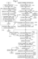
- FIG. 2 is a flowchart showing a private print process
- FIG. 3 is a schematic drawing showing an example of a window for a print job
- FIG. 4 is a schematic drawing showing an example of a pop-up screen
- FIG. 5 is a schematic drawing showing an example of a QR code.
- FIG. 1 illustrates a configuration of the image processing system Sy according to the embodiment of the disclosure.
- FIG. 1 includes block diagrams respectively showing the configuration of an image forming apparatus 10 and a personal computer (PC) 30 , included in the image processing system Sy.
- the image forming apparatus 10 , the PC 30 , and a plurality of mobile terminals 50 are connected to one another, via a network N (e.g., intranet).
- the PC 30 and the mobile terminals 50 exemplify the information processing apparatus in the disclosure.
- the image forming apparatus 10 is a multifunction peripheral (MFP) having a plurality of functions, such as a copying function, a printing function, and a scanning function.
- the image forming apparatus 10 includes a display device 11 , an operation device 12 , a communication device 14 , a touch panel 13 , an image reading device 15 , an image forming device 16 , a code reader 17 , a storage device 18 , and a control device 19 .
- the mentioned components are configured to transmit and receive data and signals to and from each other, via a bus.
- the display device 11 is, for example, constituted of a liquid crystal display (LCD) or an organic light-emitting diode (OLED) display.
- the operation device 12 includes hard keys such as a tenkey, an enter key, and a start key.
- a touch panel 13 is overlaid on the screen of the display device 11 .
- the touch panel 13 detects a contact (touch) of the user's finger made thereon, along with the touched position, and outputs a detection signal indicating the coordinate of the touched position, to a controller 21 of the control device 19 to be subsequently described. Therefore, the user can operate a graphical user interface (GUI) displayed on the screen of the display device 11 , through the touch panel 13 .
- GUI graphical user interface
- the touch panel 13 serves as an operation device for the user to input instructions through the screen of the display device 11 .
- the image reading device 15 includes a scanner that optically reads an image of a source document placed on the contact glass.
- the image reading device 15 generates image data representing the image of the source document.
- the image forming device 16 includes a photoconductor drum, a charging device that uniformly charges the surface of the photoconductor drum, an exposure device that exposes the surface of the photoconductor drum to light, thereby forming an electrostatic latent image on the surface of the photoconductor drum, a developing device that develops the electrostatic latent image on the surface of the photoconductor drum into a toner image, and a transfer device that transfers the toner image on the surface of the photoconductor drum onto a recording sheet, exemplifying the recording medium in the disclosure.
- the image forming device 16 prints the image represented by the image data, on the recording sheet.
- the communication device 14 is a communication interface including a communication module such as a local area network (LAN) chip.
- the communication device 14 is connected to the PC 30 and the mobile terminal 50 , via the network N.
- the communication device 14 performs data communication with the PC 30 or the mobile terminal 50 .
- LAN local area network
- the code reader 17 is, for example, an image camera capable of reading a QR code (registered trademark).
- the QR code exemplifies the print approval code in the disclosure. Either of a one-dimensional barcode and a two-dimensional barcode may be employed as the print approval code. In this embodiment, the QR code (registered trademark) is adopted as the two-dimensional barcode.
- the storage device 18 is a large-capacity memory unit such as a solid-state drive (SSD) or a hard disk drive (HDD).
- the storage device 18 contains various application programs and various types of data.
- the control device 19 includes a processor, a random-access memory (RAM), a read-only memory (ROM), and so forth.
- the processor is, for example, a central processing unit (CPU), an application specific integrated circuit (ASIC), or a micro processing unit (MPU).
- the control device 19 acts as the controller 21 (exemplifying the second controller), when the processor executes a second control program stored in the ROM or the storage device 18 .
- the controller 21 serves to control the overall operation of the image forming apparatus 10 .
- the control device 19 is connected to the display device 11 , the operation device 12 , the touch panel 13 , the communication device 14 , the image reading device 15 , the image forming device 16 , the code reader 17 , and the storage device 18 .
- the controller 21 controls the operation of the mentioned components, and transmits and receives data and signals to and from each of those components.
- the controller 21 serves as a processing device that executes various types of operations.
- the controller 21 is configured to control the display device 11 and the communication device 14 .
- the controller 21 extracts and acquires the QR code from the image read by the code reader 17 .
- the PC 30 includes a display device 31 , an operation device 32 , a communication device 34 , a storage device 38 , and a control device 39 . These components are configured to transmit and receive data and signals to and from each other, via a bus.
- the display device 31 is constituted of a liquid crystal display or an organic electroluminescence display.
- the operation device 32 includes a keyboard and a pointing device, to be operated by the user.
- the communication device 34 is a communication interface.
- the communication device 34 is connected to the image forming apparatus 10 via the network N, and transmits and receives data to and from the image forming apparatus 10 .
- the storage device 38 is a large-capacity memory unit such as an SSD or an HDD.
- the storage device 38 contains various application programs and various types of data.
- the control device 39 includes a processor, a RAM, a ROM, and so forth.
- the control device 39 acts as a controller 41 (exemplifying the first controller), when the processor executes a first control program stored in the ROM or the storage device 38 .
- the controller 41 serves to control the overall operation of the PC 30 .
- the control device 39 is connected to the display device 31 , the operation device 32 , the communication device 34 , and the storage device 38 .
- the controller 41 controls the operation of the mentioned components, and transmits and receives data and signals to and from each of those components.
- the controller 41 serves as a processing device that executes an operation according to an instruction inputted through the operation device 32 .
- the controller 41 is configured to control the display device 31 and the communication device 34 .
- Each of the plurality of mobile terminals 50 is, for example, a smartphone or a mobile tablet.
- the plurality of mobile terminals 50 are each connected to a server via the network N.
- the following refers to the case where the user has inputted, to the operation device 32 of the PC 30 , an instruction to transmit a print job (image file and print setting information inclusive) through the GUI displayed on the screen of the display device 31 .
- the controller 41 of the PC 30 activates the printer driver (application program), and causes the printer driver to transmit the print job from the communication device 34 to the image forming apparatus 10 , via the network N.
- the controller 21 executes the print job received, by inputting the image in the file to the image forming device 16 , and causing the image forming device 16 to form the image on the recording sheet.
- the user moves to the location where the image forming apparatus 10 is installed, to acquire the recording sheet on which the image has been recorded.
- the recording sheet is exposed on the image forming apparatus 10 until the user picks up the recording sheet from the image forming apparatus 10 .
- Such a situation is undesirable, when the image is highly confidential.
- the PC 30 transmits the print job and the respective mail addresses of a plurality of users, to the image forming apparatus 10 via the network N, so that the image forming apparatus 10 generates a QR code, and notifies the QR code to the users respectively corresponding to the plurality of mail addresses.
- the image forming apparatus 10 executes the print job, when the QR code is inputted.
- the image forming apparatus 10 inhibits the print job from being executed again on the basis of the QR code, and generates a second QR code and notifies the second QR code to the users respectively corresponding to the plurality of mail addresses.
- the image forming apparatus 10 executes the print job when the second QR code is inputted, and inhibits the print job from being executed again on the basis of the second QR code.
- the image forming apparatus 10 similarly repeats the generation, transmission, and input of additional QR codes, and the execution and inhibition of the print job, the number of times corresponding to the number of the plurality of mail addresses.
- the image processing system Sy executes such control, under a private print mode.
- the private print mode enables a plurality of users to efficiently utilize the same print job, while maintaining the confidentiality of the print job at a high level.
- the user inputs an instruction to select a file to be printed, and an instruction to execute a print job of printing the image of the file, to the operation device 32 of the PC 30 , through the GUI displayed on the screen of the display device 31 .
- the controller 41 of the PC 30 activates the printer driver in response to the selection instruction and the execution instruction, and causes the display device 31 to display a window PW for the print job, as shown in FIG. 3 (step S 101 ).
- the controller 41 causes the display device 31 to display, in the window PW for the print job, the name of the selected file to be printed (identification information) FM, a box B 11 for inputting the name of the image forming apparatus 10 (identification information), a box B 12 for inputting the log-in password of the user, a key K 11 indicating the private print mode, an OK key K 12 , and a cancel key K 13 .
- the user can respectively input the name of the image forming apparatus 10 , and the log-in password of the user through the boxes B 11 and B 12 , and the instruction to set the private print mode through the key K 11 , by operating the operation device 32 of the PC 30 .
- the controller 41 of the PC 30 sets the private print mode (Yes at step S 102 ), and causes the display device 31 to display a pop-up screen PG, as shown in FIG. 4 (step S 103 ).
- the controller 41 causes the display device 31 to display, in the pop-up screen PG, a box B 21 in which the user's mail address is inputted in advance, a box B 22 for inputting the mail address of another user, an addition key K 21 , an OK key K 22 , and a cancel key K 23 .
- the user confirms his/her own mail address inputted in advance in the box B 21 , selects the box B 22 through the operation device 32 , and inputs the mail address of another user than him/herself in the box B 22 .
- the controller 41 upon receipt of the instruction to add the user, inputted through the addition key K 21 , the controller 41 causes the display device 31 to additionally display the box B 22 .
- the controller 41 causes the display device 31 to additionally display the box B 22 in the pop-up screen PG, each time the instruction to add the user is received.
- the controller 41 receives the input of the mail address of another user through the added box B 22 , according to the user's operation performed on the operation device 32 .
- the controller 41 Upon receipt of an instruction to acquire the mail address through the OK key K 22 in the pop-up screen PG, according to the user's operation performed on the operation device 32 , the controller 41 acquires the respective mail addresses inputted in the box B 21 and the box B 22 (step S 104 ), and closes the pop-up screen PG.
- the controller 41 transmits the print job for printing the image of the file to be printed, and the log-in password of the user, from the communication device 34 to the image forming apparatus 10 via the network N, together with the private print mode setting instruction, the user's mail address, and the mail address of the other user (step S 105 ).
- the controller 41 closes the pop-up screen PG without performing the operation of step S 104 , and again causes the display device 31 to display the window PW for the print job shown in FIG. 3 (step S 101 ). Then upon receipt of the instruction to cancel the job through the cancel key K 13 in the window PW, according to the user's operation performed on the operation device 32 , the controller 41 cancels the print job instead of executing the print job, and closes the window PW.
- the controller 41 skips the setting of the private print mode, and transmits the print job for printing the image of the file to be printed, and the log-in password of the user, from the communication device 34 to the image forming apparatus 10 via the network N (step S 106 ).
- the communication device 14 of the image forming apparatus 10 receives the print job and the log-in password of the user, or the print job, the log-in password of the user, the private print mode setting instruction, the user's mail address, and the mail address of the other user (step S 201 ).
- the controller 21 of the image forming apparatus 10 decides whether the log-in password of the user accords with any of the plurality of log-in passwords included in a log-in management table stored in advance in the storage device 18 . Upon deciding that the log-in password of the user accords with one of the plurality of log-in passwords, the controller 21 authenticates the log-in password of the user, and permits the user corresponding to the authenticated log-in password to log in in the image forming apparatus 10 (step S 202 ).
- the controller 21 decides whether the private print mode setting instruction has been received (step S 203 ). Upon deciding that the private print mode setting instruction has not been received, in other words that only the print job and the user's log-in password have been received (No at step S 203 ), the controller 21 skips the setting of the private print mode, and performs the normal print operation by immediately executing the print job (step S 204 ). More specifically, the controller 21 inputs the image of the file to be printed in the image forming device 16 , and causes the image forming device 16 to form the image on the recording sheet.
- the controller 21 sets the private print mode (step S 205 ), and stores the print job received at step S 201 in the RAM 22 in the control device 19 (step S 206 ).
- the controller 21 then generates the QR code (step S 207 ), and e-mails each addressed to the user's mail address and the other user's mail address received at step S 201 , and transmits those e-mails, with the QR code attached to each of the e-mails, from the communication device 14 to the server on the network N (step S 208 ).
- the controller 21 also stores the QR code in the RAM 22 in the control device 19 , in association with the print job received at step S 201 (step S 209 ).
- the controller 21 When generating the QR code, the controller 21 includes the information such as the name of the file to be printed by the print job, and a time stamp, in the QR code.
- the QR code represents the identification information of the print job.
- Those mobile terminals 50 each include a controller, for example including a CPU, and a display device, for example including an LCD.
- the controllers of the respective mobile terminals 50 cause the respective display devices to display the QR code attached to the e-mails, on the screen of the respective mobile terminals 50 .
- a QR code (two-dimensional code) Q 1 is displayed, for example as shown in FIG. 5 .
- the controller 21 of the image forming apparatus 10 displays a message urging the user to input the QR code, on the screen of the display device 11 , and stands by for the input of the QR code (No at step S 210 ).
- the user goes to the image forming apparatus 10 , with the mobile terminal 50 on which the QR code Q 1 is displayed, and inputs the QR code Q 1 displayed on the screen of the mobile terminal 50 , by causing the code reader 17 to read the QR code Q 1 .
- the controller 21 of the image forming apparatus 10 decides whether the QR code Q 1 which has been inputted accords with the QR code stored in the RAM 22 at step S 209 (step S 211 ).
- the controller 21 Upon deciding that the inputted QR code Q 1 discords with the QR code stored in the RAM 22 at step S 209 (No at step S 211 ), the controller 21 causes the display device 11 to display a message notifying the input error of the QR code, on the screen (step S 212 ). After step S 212 , the controller 21 returns to step S 210 .
- the controller 21 retrieves the print job associated with the QR code at step S 209 from the RAM 22 , and executes the print job.
- the controller 21 inputs the image of the file to be printed in the image forming device 16 , and causes the image forming device 16 to form the image on the recording sheet (step S 213 ).
- the controller 21 also erases the QR code associated with the print job, from the RAM 22 (step S 214 ). Such an operation prevents the print job associated with the QR code Q 1 from being retrieved from the RAM 22 and executed, even though the QR code Q 1 is again read by the code reader 17 and inputted. As result, the execution of the print job, based on the repeated input of the QR code Q 1 , can be inhibited.
- the controller 21 counts the number of times of execution N of the print job (step S 215 ), and decides whether the number of times of execution N accords with the number of mail addresses n, to which the QR code generated at step S 207 was transmitted, in other words the number of users who received the QR code (step S 216 ).
- the controller 21 when the controller 21 decides that the number of times of execution N of the print job discords with the number of the plurality of mail addresses n, to each of which the e-mail was transmitted at step S 208 (No at step S 216 ), it means that one or more users have not executed the print job, despite receiving the QR code. Therefore, the controller 21 generates the second QR code, different from the QR code generated at step S 207 (step S 217 ).
- the controller 21 generates e-mails each addressed to the user's mail address and the other user's mail address received at step S 201 , and transmits those e-mails, with the second QR code attached to each of the e-mails, from the communication device 14 to the server on the network N (step S 218 ).
- the controller 21 stores the second QR code in the RAM 22 in the control device 19 , in association with the print job received at step S 201 (step S 219 ). After step S 219 , the controller 21 returns to step S 210 .
- the controller 21 When generating the second QR code, the controller 21 includes the information such as the name of the file to be printed by the print job, and a new time stamp, in the second QR code.
- the second QR code represents the identification information of the print job.
- the identification information of the print job indicated by the second QR code is different from the identification information of the print job indicated by the QR code generated first.
- the respective controllers of those mobile terminals 50 each cause the display device to display the QR code attached to the e-mail.
- the controller 21 of the image forming apparatus 10 displays a message urging the user to input the QR code, on the screen of the display device 11 , and stands by for the input of the QR code (No at step S 210 ).
- the controller 21 decides whether the QR code Q 1 which has been inputted accords with the second QR code stored in the RAM 22 at step S 219 (step S 211 ).
- the controller 21 Upon deciding that the inputted QR code Q 1 discords with the second QR code (No at step S 211 ), the controller 21 causes the display device 11 to display a message notifying the input error of the QR code, on the screen (step S 212 ). After step S 212 , the controller 21 returns to step S 210 .
- the controller 21 retrieves the print job associated with the second QR code at step S 219 from the RAM 22 , and executes the print job to print the image of the file to be printed (step S 213 ). Then the controller 21 erases the second QR code associated with the print job that has been executed, from the RAM 22 (step S 214 ). As result, the execution of the print job, based on the repeated input of the second QR code, can be inhibited.
- the controller 21 counts the number of times of execution N of the print job (step S 215 ).
- the controller 21 generates a third QR code, different from the second QR code generated at step S 207 (step S 217 ).
- the controller 21 generates e-mails each addressed to the user's mail address and the other user's mail address received at step S 201 , and transmits those e-mails, with the third QR code attached to each of the e-mails, to the server on the network N (step S 218 ).
- the controller 21 stores the third QR code in the RAM 22 in the control device 19 , in association with the print job received at step S 201 (step S 219 ).
- step S 210 when the code reader 17 reads the QR code Q 1 (Yes at step S 210 ), and the QR code Q 1 which has been read accords with the third QR code stored in the RAM 22 at step S 219 (Yes at step S 211 ), the controller executes the print job (step S 213 ), and erases the QR code associated with the print job, from the RAM 22 (step S 214 ).
- the controller 21 then counts the number of times of execution N of the print job (step S 215 ), and generates a fourth QR code (step S 217 ), which is different from the QR code previously generated at step S 217 , when the number of times of execution N discords with the number of the plurality of mail addresses n, to each of which the e-mail was transmitted at step S 208 (No at step S 216 ).
- the controller 21 transmits e-mails addressed to the respective users, with the fourth QR code attached to each of the e-mails, to the server on the network N (step S 218 ), and stores the fourth QR code in the RAM 22 in the control device 19 , in association with the print job received at step S 201 (step S 219 ).
- step S 216 the controller 21 decides that there is no longer a user who has not executed the print job, and erases the print job received at step S 201 from the RAM 22 , thereby invalidating the print job (step S 220 ). After step S 220 , the controller 21 finishes the process.
- the controller 21 sets the number of mail address n to “1”.
- the controller 21 sets the number of times of execution N of the print job to “1”, and erases the print job from the RAM 22 thereby invalidating the print job (step S 220 ), on the basis of the decision that N equals to n (Yes at step S 216 ).
- the controller 21 finishes the process.
- the controller 21 sets the number of mail addresses n to “2”.
- the controller 21 sets the number of times of execution N of the print job to “1”, and therefore does not decide that N equals to n (No at step S 216 ).
- the controller 21 generates, transmits, and stores the second QR code (step S 217 to step S 219 ). Then upon executing the print job again under the mentioned state (step S 213 ), the controller 21 sets the number of times of execution N of the print job to “2”.
- the controller 21 sets the number of mail addresses n to “3” or larger, repeats the generation, transmission, and storage of additional QR codes (step S 217 to step S 219 ), and sequentially executes the print job (step S 213 ).
- the controller 21 erases the print job received at step S 201 from the RAM 22 , thereby invalidating the print job (step S 220 ). After step S 220 , the controller 21 finishes the process.
- a client terminal transmits a two-dimensional barcode to the mobile terminals of the respective users
- an authentication device reads the two-dimensional barcode displayed on the screen of each of the mobile terminals and transmits a print request to the client terminal
- the client terminal transmits the print job to a printer terminal
- the printer terminal executes the print job.
- the QR code is generated by the image forming apparatus 10 , and notified to the users respectively corresponding to the plurality of mail addresses.
- the QR code is inputted to the image forming apparatus 10
- the print job is executed by the image forming apparatus 10
- the repeated execution of the print job based on the QR code is inhibited.
- the second QR code is generated by the image forming apparatus 10 , and notified to the users respectively corresponding to the plurality of mail addresses.
- the second QR code is inputted to the image forming apparatus 10
- the print job is executed by the image forming apparatus 10 , and the repeated execution of the print job based on the second QR code is inhibited.
- the QR code is changed each time the print job is executed, and the print job is erased, when the number of times of execution N of the print job has reached the number of the plurality of mail addresses n, so that these numbers accord with each other. Therefore, the confidentiality of the print job can be maintained at a high level.
- the controller 21 changes the QR code each time the print job is executed, in the foregoing embodiment, the disclosure is not limited to such embodiment.
- the controller 21 may generate, at a time, the same number of QR codes different from each other, as the number of the plurality of mail addresses, with respect to the same print job.
- the controller 21 of the image forming apparatus 10 upon setting the private print mode, the controller 21 of the image forming apparatus 10 generates the same number of QR codes different from each other, as the number of the plurality of mail addresses, and also generates the e-mails addressed to the respective mail addresses.
- the controller 21 assigns the QR codes to the respective e-mails as annex thereto, transmits these e-mails to the server on the network N, and stores the QR codes in the RAM 22 in association with the print job.
- the controller 21 executes the print job, when the QR code read by the code reader 17 accords with one of the QR codes associated with the print job, and erases the QR code that has accorded from the RAM 22 , thereby inhibiting the execution of the print job based on the repeated input of the QR code.
- the controller 21 erases the print job, thereby invalidating the same.
- Such an arrangement also enables the confidentiality of the print job to be maintained at a high level, while allowing a plurality of users to efficiently utilize the same print job.
- print approval code is exemplified by the QR code in the foregoing embodiment, a two-dimensional code of a different type, or a one-dimensional code such as a barcode, may be employed instead.
Abstract
Description
Claims (4)
Applications Claiming Priority (2)
| Application Number | Priority Date | Filing Date | Title |
|---|---|---|---|
| JP2021-119971 | 2021-07-20 | ||
| JP2021119971A JP2023015896A (en) | 2021-07-20 | 2021-07-20 | Image processing system |
Publications (2)
| Publication Number | Publication Date |
|---|---|
| US20230024703A1 US20230024703A1 (en) | 2023-01-26 |
| US11809761B2 true US11809761B2 (en) | 2023-11-07 |
Family
ID=84977739
Family Applications (1)
| Application Number | Title | Priority Date | Filing Date |
|---|---|---|---|
| US17/864,284 Active US11809761B2 (en) | 2021-07-20 | 2022-07-13 | Image processing system that transmits a second print approval code to each of plurality of mail addresses, when private print mode is set, and executes print job when first print approval code received through input device accords with second print approval code |
Country Status (2)
| Country | Link |
|---|---|
| US (1) | US11809761B2 (en) |
| JP (1) | JP2023015896A (en) |
Citations (6)
| Publication number | Priority date | Publication date | Assignee | Title |
|---|---|---|---|---|
| US20030007172A1 (en) * | 2001-06-12 | 2003-01-09 | Masahiro Takayanagi | Printing apparatus, its control method, print system, program, and memory medium |
| JP2008192051A (en) | 2007-02-07 | 2008-08-21 | Silex Technology Inc | Secure print system and secure print method using portable terminal |
| EP2500851A1 (en) * | 2011-03-18 | 2012-09-19 | Oki Data Corporation | Information processing apparatus, multi function printer, and image reading apparatus |
| US20140092413A1 (en) * | 2012-09-28 | 2014-04-03 | Brother Kogyo Kabushiki Kaisha | System, server, communication device, and computer readable medium therefor |
| US20160253127A1 (en) * | 2015-02-27 | 2016-09-01 | Kyocera Document Solutions Inc. | Print Data Retrieval System using Graphical Codes |
| US20180285036A1 (en) * | 2017-04-02 | 2018-10-04 | Kyocera Document Solutions Inc. | System and method for pre-generation of page description language (pdl) for printing |
-
2021
- 2021-07-20 JP JP2021119971A patent/JP2023015896A/en active Pending
-
2022
- 2022-07-13 US US17/864,284 patent/US11809761B2/en active Active
Patent Citations (6)
| Publication number | Priority date | Publication date | Assignee | Title |
|---|---|---|---|---|
| US20030007172A1 (en) * | 2001-06-12 | 2003-01-09 | Masahiro Takayanagi | Printing apparatus, its control method, print system, program, and memory medium |
| JP2008192051A (en) | 2007-02-07 | 2008-08-21 | Silex Technology Inc | Secure print system and secure print method using portable terminal |
| EP2500851A1 (en) * | 2011-03-18 | 2012-09-19 | Oki Data Corporation | Information processing apparatus, multi function printer, and image reading apparatus |
| US20140092413A1 (en) * | 2012-09-28 | 2014-04-03 | Brother Kogyo Kabushiki Kaisha | System, server, communication device, and computer readable medium therefor |
| US20160253127A1 (en) * | 2015-02-27 | 2016-09-01 | Kyocera Document Solutions Inc. | Print Data Retrieval System using Graphical Codes |
| US20180285036A1 (en) * | 2017-04-02 | 2018-10-04 | Kyocera Document Solutions Inc. | System and method for pre-generation of page description language (pdl) for printing |
Also Published As
| Publication number | Publication date |
|---|---|
| US20230024703A1 (en) | 2023-01-26 |
| JP2023015896A (en) | 2023-02-01 |
Similar Documents
| Publication | Publication Date | Title |
|---|---|---|
| US10630858B2 (en) | Document approval management system for creating document approval workflow | |
| EP2770718B1 (en) | Printing apparatus, printing method, and storage medium | |
| US20120198534A1 (en) | Information processing system, apparatus, method, and program storage medium | |
| JP2020155104A (en) | Method and system for generating confidential document | |
| US20210377277A1 (en) | Service providing system, information processing system, and use permission assigning method | |
| JP2010244449A (en) | Information processing apparatus, method of controlling the same, and program | |
| KR20170131123A (en) | Printing method of image forminig apparatus and the image forminig apparatus | |
| US20150242170A1 (en) | Image forming apparatus, job execution system, and job execution method | |
| US11611668B2 (en) | Image processing system that generates job setting information based on interaction with user of information processing apparatus using chatbot | |
| CN103139422B (en) | Image processing apparatus and control method thereof | |
| JP2007004292A (en) | Program and information processor | |
| JP2016100866A (en) | Information processing apparatus, information processing system, control method of information processing apparatus, and program | |
| JP2013187836A (en) | Information processing system, information processing device, and information processing method | |
| CN112714234B (en) | Information processing apparatus, storage medium, and user management method | |
| US9258438B2 (en) | Information processing apparatus, information processing terminal, and information processing system | |
| JP5412335B2 (en) | Image forming system | |
| JP6686783B2 (en) | Image forming system and printing method | |
| US20230351008A1 (en) | Information processing device and method for managing history information of information processing device | |
| US10033909B2 (en) | Print management apparatus, computer readable recording medium stored with print management program, print management system, and image forming apparatus capable of maintaining security without depending on only consciousness of an individual | |
| US11809761B2 (en) | Image processing system that transmits a second print approval code to each of plurality of mail addresses, when private print mode is set, and executes print job when first print approval code received through input device accords with second print approval code | |
| JP2020155107A (en) | Method and system for managing confidential documents over multiple devices | |
| JP5358490B2 (en) | Image forming system and user manager server device | |
| US20200394004A1 (en) | Apparatus and method for sharing a printable electronic document between users | |
| JP6958293B2 (en) | Print control device, control method and program of print control device | |
| JP5033205B2 (en) | Image forming system and user manager server device |
Legal Events
| Date | Code | Title | Description |
|---|---|---|---|
| AS | Assignment |
Owner name: KYOCERA DOCUMENT SOLUTIONS INC., JAPAN Free format text: ASSIGNMENT OF ASSIGNORS INTEREST;ASSIGNOR:OPLADO, VICTORIE MAIA;REEL/FRAME:060500/0580 Effective date: 20220701 |
|
| FEPP | Fee payment procedure |
Free format text: ENTITY STATUS SET TO UNDISCOUNTED (ORIGINAL EVENT CODE: BIG.); ENTITY STATUS OF PATENT OWNER: LARGE ENTITY |
|
| STPP | Information on status: patent application and granting procedure in general |
Free format text: DOCKETED NEW CASE - READY FOR EXAMINATION |
|
| STPP | Information on status: patent application and granting procedure in general |
Free format text: NON FINAL ACTION MAILED |
|
| STPP | Information on status: patent application and granting procedure in general |
Free format text: RESPONSE TO NON-FINAL OFFICE ACTION ENTERED AND FORWARDED TO EXAMINER |
|
| STPP | Information on status: patent application and granting procedure in general |
Free format text: NOTICE OF ALLOWANCE MAILED -- APPLICATION RECEIVED IN OFFICE OF PUBLICATIONS |
|
| STPP | Information on status: patent application and granting procedure in general |
Free format text: PUBLICATIONS -- ISSUE FEE PAYMENT VERIFIED |
|
| STCF | Information on status: patent grant |
Free format text: PATENTED CASE |