US11808451B1 - Flue cap with filter - Google Patents
Flue cap with filter Download PDFInfo
- Publication number
- US11808451B1 US11808451B1 US17/399,914 US202117399914A US11808451B1 US 11808451 B1 US11808451 B1 US 11808451B1 US 202117399914 A US202117399914 A US 202117399914A US 11808451 B1 US11808451 B1 US 11808451B1
- Authority
- US
- United States
- Prior art keywords
- flue
- fanned
- pipe
- filter
- cap
- Prior art date
- Legal status (The legal status is an assumption and is not a legal conclusion. Google has not performed a legal analysis and makes no representation as to the accuracy of the status listed.)
- Active, expires
Links
- MWUXSHHQAYIFBG-UHFFFAOYSA-N Nitric oxide Chemical compound O=[N] MWUXSHHQAYIFBG-UHFFFAOYSA-N 0.000 claims abstract description 100
- 239000007789 gas Substances 0.000 claims abstract description 12
- 238000001914 filtration Methods 0.000 description 3
- MGWGWNFMUOTEHG-UHFFFAOYSA-N 4-(3,5-dimethylphenyl)-1,3-thiazol-2-amine Chemical compound CC1=CC(C)=CC(C=2N=C(N)SC=2)=C1 MGWGWNFMUOTEHG-UHFFFAOYSA-N 0.000 description 2
- QGZKDVFQNNGYKY-UHFFFAOYSA-N Ammonia Chemical compound N QGZKDVFQNNGYKY-UHFFFAOYSA-N 0.000 description 2
- 238000003915 air pollution Methods 0.000 description 2
- 239000003546 flue gas Substances 0.000 description 2
- JCXJVPUVTGWSNB-UHFFFAOYSA-N nitrogen dioxide Inorganic materials O=[N]=O JCXJVPUVTGWSNB-UHFFFAOYSA-N 0.000 description 2
- UGFAIRIUMAVXCW-UHFFFAOYSA-N Carbon monoxide Chemical compound [O+]#[C-] UGFAIRIUMAVXCW-UHFFFAOYSA-N 0.000 description 1
- CBENFWSGALASAD-UHFFFAOYSA-N Ozone Chemical compound [O-][O+]=O CBENFWSGALASAD-UHFFFAOYSA-N 0.000 description 1
- XSQUKJJJFZCRTK-UHFFFAOYSA-N Urea Chemical compound NC(N)=O XSQUKJJJFZCRTK-UHFFFAOYSA-N 0.000 description 1
- 238000003916 acid precipitation Methods 0.000 description 1
- 229910021529 ammonia Inorganic materials 0.000 description 1
- 239000000926 atmospheric chemistry Substances 0.000 description 1
- 230000015572 biosynthetic process Effects 0.000 description 1
- 239000004202 carbamide Substances 0.000 description 1
- 239000000470 constituent Substances 0.000 description 1
- 238000009432 framing Methods 0.000 description 1
- 238000009434 installation Methods 0.000 description 1
- 239000000463 material Substances 0.000 description 1
- 239000002184 metal Substances 0.000 description 1
- 229910001220 stainless steel Inorganic materials 0.000 description 1
- 239000010935 stainless steel Substances 0.000 description 1
Images


Classifications
-
- F—MECHANICAL ENGINEERING; LIGHTING; HEATING; WEAPONS; BLASTING
- F23—COMBUSTION APPARATUS; COMBUSTION PROCESSES
- F23J—REMOVAL OR TREATMENT OF COMBUSTION PRODUCTS OR COMBUSTION RESIDUES; FLUES
- F23J15/00—Arrangements of devices for treating smoke or fumes
- F23J15/02—Arrangements of devices for treating smoke or fumes of purifiers, e.g. for removing noxious material
-
- B—PERFORMING OPERATIONS; TRANSPORTING
- B01—PHYSICAL OR CHEMICAL PROCESSES OR APPARATUS IN GENERAL
- B01D—SEPARATION
- B01D46/00—Filters or filtering processes specially modified for separating dispersed particles from gases or vapours
- B01D46/0002—Casings; Housings; Frame constructions
- B01D46/0017—Filter elements installed in a branch of a pipe, e.g. with an y-shaped tubular housing
-
- B—PERFORMING OPERATIONS; TRANSPORTING
- B01—PHYSICAL OR CHEMICAL PROCESSES OR APPARATUS IN GENERAL
- B01D—SEPARATION
- B01D46/00—Filters or filtering processes specially modified for separating dispersed particles from gases or vapours
- B01D46/0027—Filters or filtering processes specially modified for separating dispersed particles from gases or vapours with additional separating or treating functions
- B01D46/003—Filters or filtering processes specially modified for separating dispersed particles from gases or vapours with additional separating or treating functions including coalescing means for the separation of liquid
- B01D46/0031—Filters or filtering processes specially modified for separating dispersed particles from gases or vapours with additional separating or treating functions including coalescing means for the separation of liquid with collecting, draining means
-
- B—PERFORMING OPERATIONS; TRANSPORTING
- B01—PHYSICAL OR CHEMICAL PROCESSES OR APPARATUS IN GENERAL
- B01D—SEPARATION
- B01D46/00—Filters or filtering processes specially modified for separating dispersed particles from gases or vapours
- B01D46/10—Particle separators, e.g. dust precipitators, using filter plates, sheets or pads having plane surfaces
-
- B—PERFORMING OPERATIONS; TRANSPORTING
- B01—PHYSICAL OR CHEMICAL PROCESSES OR APPARATUS IN GENERAL
- B01D—SEPARATION
- B01D46/00—Filters or filtering processes specially modified for separating dispersed particles from gases or vapours
- B01D46/24—Particle separators, e.g. dust precipitators, using rigid hollow filter bodies
- B01D46/2403—Particle separators, e.g. dust precipitators, using rigid hollow filter bodies characterised by the physical shape or structure of the filtering element
- B01D46/2418—Honeycomb filters
-
- B—PERFORMING OPERATIONS; TRANSPORTING
- B01—PHYSICAL OR CHEMICAL PROCESSES OR APPARATUS IN GENERAL
- B01D—SEPARATION
- B01D53/00—Separation of gases or vapours; Recovering vapours of volatile solvents from gases; Chemical or biological purification of waste gases, e.g. engine exhaust gases, smoke, fumes, flue gases, aerosols
- B01D53/34—Chemical or biological purification of waste gases
- B01D53/46—Removing components of defined structure
- B01D53/54—Nitrogen compounds
- B01D53/56—Nitrogen oxides
-
- F—MECHANICAL ENGINEERING; LIGHTING; HEATING; WEAPONS; BLASTING
- F23—COMBUSTION APPARATUS; COMBUSTION PROCESSES
- F23J—REMOVAL OR TREATMENT OF COMBUSTION PRODUCTS OR COMBUSTION RESIDUES; FLUES
- F23J15/00—Arrangements of devices for treating smoke or fumes
- F23J15/02—Arrangements of devices for treating smoke or fumes of purifiers, e.g. for removing noxious material
- F23J15/022—Arrangements of devices for treating smoke or fumes of purifiers, e.g. for removing noxious material for removing solid particulate material from the gasflow
- F23J15/025—Arrangements of devices for treating smoke or fumes of purifiers, e.g. for removing noxious material for removing solid particulate material from the gasflow using filters
-
- B—PERFORMING OPERATIONS; TRANSPORTING
- B01—PHYSICAL OR CHEMICAL PROCESSES OR APPARATUS IN GENERAL
- B01D—SEPARATION
- B01D2251/00—Reactants
- B01D2251/20—Reductants
- B01D2251/206—Ammonium compounds
- B01D2251/2062—Ammonia
-
- B—PERFORMING OPERATIONS; TRANSPORTING
- B01—PHYSICAL OR CHEMICAL PROCESSES OR APPARATUS IN GENERAL
- B01D—SEPARATION
- B01D2258/00—Sources of waste gases
- B01D2258/02—Other waste gases
- B01D2258/0283—Flue gases
-
- F—MECHANICAL ENGINEERING; LIGHTING; HEATING; WEAPONS; BLASTING
- F23—COMBUSTION APPARATUS; COMBUSTION PROCESSES
- F23J—REMOVAL OR TREATMENT OF COMBUSTION PRODUCTS OR COMBUSTION RESIDUES; FLUES
- F23J2213/00—Chimneys or flues
- F23J2213/50—Top cover
-
- F—MECHANICAL ENGINEERING; LIGHTING; HEATING; WEAPONS; BLASTING
- F23—COMBUSTION APPARATUS; COMBUSTION PROCESSES
- F23J—REMOVAL OR TREATMENT OF COMBUSTION PRODUCTS OR COMBUSTION RESIDUES; FLUES
- F23J2215/00—Preventing emissions
- F23J2215/10—Nitrogen; Compounds thereof
-
- F—MECHANICAL ENGINEERING; LIGHTING; HEATING; WEAPONS; BLASTING
- F23—COMBUSTION APPARATUS; COMBUSTION PROCESSES
- F23J—REMOVAL OR TREATMENT OF COMBUSTION PRODUCTS OR COMBUSTION RESIDUES; FLUES
- F23J2215/00—Preventing emissions
- F23J2215/10—Nitrogen; Compounds thereof
- F23J2215/101—Nitrous oxide (N2O)
Definitions
- the embodiments described herein relate generally to reducing nitrogen oxide (NOx) emissions and, more particularly, to a flue cap with a filter to reduce NOx emissions from gas appliances.
- NOx nitrogen oxide
- NOx is a generic term for the nitrogen oxides that are most relevant for air pollution, namely nitric oxide (NO) and nitrogen dioxide (NO 2 ). These gases contribute to the formation of smog and acid rain, as well as affecting tropospheric ozone.
- NOx flue gasses are allowed to escape from gas appliances through a flue pipe system at the rate of emission allowed by the gas fired appliance.
- most gas-fired appliances in use today also do not meet current emission standards, as they were installed years ago.
- the flue pipe filter device may include a flue cap with a pipe connection adapter sized to attach to an existing exhaust pipe; a fanned flue cap body with vents operatively attached to a distal end of the pipe connection adapter; and a filter positioned within the fanned flue cap body, the filter designed to convert NOx emissions into reduced NOx emissions.
- the filter may have an interior honeycomb structure.
- FIG. 1 is a perspective view of one embodiment of the present disclosure, shown in use.
- FIG. 2 is a perspective view of one embodiment of the present disclosure.
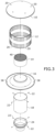
- FIG. 3 is an exploded view of one embodiment of the present disclosure.
- FIG. 4 is a partial section view of one embodiment of the present disclosure taken along line 4 - 4 in FIG. 1 .
- the device of the present disclosure may be used to reduce nitrogen oxide (NOx) emission levels from gas fired appliances and may comprise the following elements.
- NOx nitrogen oxide
- This list of possible constituent elements is intended to be exemplary only, and it is not intended that this list be used to limit the device of the present application to just these elements. Persons having ordinary skill in the art relevant to the present disclosure may understand there to be equivalent elements that may be substituted within the present disclosure without changing the essential function or operation of the device.
- some embodiments of the present disclosure include a flue pipe filter device for reducing NOx emission levels from gas fired appliances, the device comprising a flue cap with a pipe connection adapter 24 sized to attach to an existing exhaust pipe 26 that is operatively attached to at least one gas fired appliance 28 , a fanned flue cap body with vents operatively attached to a distal end of the pipe connection adapter 24 , and a filter 14 designed to convert NOx emissions 32 into reduced NOx emissions 34 , wherein exhaust flows from the appliances 28 through the exhaust pipe 26 , through the pipe connection adapter 24 , into the fanned flue cap body through the filter 14 , and out of the fanned flue cap body through the vents.
- the pipe connector adapter 24 may be attached to a lower flue 18 , wherein a distal end of the lower flue 18 is attached to the fanned flue cap body.
- the fanned flue cap body may comprise a lower cap 16 with a central tubular member sized to attached to the lower flue, wherein the filter 14 is sized to fit within the tubular member of the lower cap 16 .
- a vent body 12 comprising a plurality of vents may be engaged with a top surface of the lower cap 16 , and a top cap 10 may close off a top opening of the vent body 12 , forcing airflow to go through the vents in the vent body 12 .
- the vents on the vent body 12 may be louvered vents.
- the pipe connector adapter 16 may have a flared portion extending from a tubular member portion, wherein the tubular member portion is designed to engage with the existing exhaust pipe 26 .
- An end of the flared portion may operatively attached to a proximal end of the lower flue 18 using conventional fasteners such as screws 22 .
- the lower flue 18 may have a substantially tubular shaped wherein a distal end of the lower flue 18 may attach to a bottom end of the central tubular member on the lower cap 16 using conventional fasteners, such as screws 22 .
- the lower cap 16 may have an angled circular plate portion extending outward from the central tubular member, wherein the angled plate portion may comprise at least one condensate drip hole 38 extending therethrough.
- the filter 14 may have a substantially cylindrical shape with a honeycomb interior structure 40 designed to filter NOx emissions.
- the vent body 12 may also be substantially cylindrical, where the vent body 12 may be attached to the lower cap 16 using a fastener, such as at least one rivet 20 .
- the vent body 12 may have a diameter larger than that of the central tubular member of the lower cap 16 , which may help ensure that all exhaust flows out through the vents.
- the top cap 10 may have a rounded shape, such as a dome shape, wherein the top cap 10 may be attached to an end of the vent body 12 using conventional fasteners, such as rivets 20 .
- the flue cap may also include an inner liner (not shown), wherein the liner may be infused with, for example, urea or ammonia to improve the NOx reducing capabilities of the flue cap.
- the shape of the flue cap may provide a vortex design to capture and filter the flue gases.
- the flue pipe filtering device may be made of any suitable materials and, in some embodiments, comprises a metal, such as stainless steel. Moreover, the flue pipe filtering device may have any suitable or necessary size for attaching to conventional exhaust pipes 26 and, in some embodiments, may attach to exhaust pipes 26 have a size of from about 2 to about 12 inches.
- the flue cap may be installed on a current or new exhaust piping system comprising an exhaust pipe 26 extending from gas-fired appliances 28 .
- an exemplary system may include the exhaust pipe 26 extending through the framing 30 and the roof 36 of the building, wherein the flue cap device of the present disclosure is designed to engage with an end of the exhaust pipe 26 extending out of the building past the roof 36 .
- the installation of the flue cap may be done via snapping, locking, twisting, and the like.
- the flue gas or NOx emissions 32 may travel from the appliance 28 , through the exhaust pipe 26 , and arrive at the flue pipe filtering device.
- the flue cap may capture the NOx gases as they pass through a vortex, thus reducing NOx gases before being expelled back out to the environment. In embodiments, the reduction may vary from about 20% to about 70%.
Landscapes
- Engineering & Computer Science (AREA)
- Chemical & Material Sciences (AREA)
- Chemical Kinetics & Catalysis (AREA)
- Mechanical Engineering (AREA)
- General Engineering & Computer Science (AREA)
- Geometry (AREA)
- Physics & Mathematics (AREA)
- Health & Medical Sciences (AREA)
- Biomedical Technology (AREA)
- Environmental & Geological Engineering (AREA)
- Analytical Chemistry (AREA)
- General Chemical & Material Sciences (AREA)
- Oil, Petroleum & Natural Gas (AREA)
- Exhaust Gas After Treatment (AREA)
- Treating Waste Gases (AREA)
Abstract
A flue pipe filter device for reducing nitrogen oxide (NOx) emission levels from gas fired appliances may include a flue cap with a pipe connection adapter sized to attach to an existing exhaust pipe; a fanned flue cap body with vents operatively attached to a distal end of the pipe connection adapter; and a filter positioned within the fanned flue cap body, the filter designed to convert NOx emissions into reduced NOx emissions. The filter may have an interior honeycomb structure.
Description
This application claims priority to provisional patent application U.S. Ser. No. 63/159,910 filed on Mar. 11, 2021, the entire contents of which is herein incorporated by reference.
The embodiments described herein relate generally to reducing nitrogen oxide (NOx) emissions and, more particularly, to a flue cap with a filter to reduce NOx emissions from gas appliances.
Air pollution is a major, global problem. In atmospheric chemistry, NOx is a generic term for the nitrogen oxides that are most relevant for air pollution, namely nitric oxide (NO) and nitrogen dioxide (NO2). These gases contribute to the formation of smog and acid rain, as well as affecting tropospheric ozone.
Conventionally NOx flue gasses are allowed to escape from gas appliances through a flue pipe system at the rate of emission allowed by the gas fired appliance. Unfortunately, most gas-fired appliances in use today also do not meet current emission standards, as they were installed years ago.
Therefore, what is needed is a device to reduce emission levels from gas-fired appliances.
Some embodiments of the present disclosure include a flue pipe filter device for reducing nitrogen oxide (NOx) emission levels from gas-fired appliances. The flue pipe filter device may include a flue cap with a pipe connection adapter sized to attach to an existing exhaust pipe; a fanned flue cap body with vents operatively attached to a distal end of the pipe connection adapter; and a filter positioned within the fanned flue cap body, the filter designed to convert NOx emissions into reduced NOx emissions. The filter may have an interior honeycomb structure.
The detailed description of some embodiments of the invention is made below with reference to the accompanying figures, wherein like numerals represent corresponding parts of the figures.
In the following detailed description of the invention, numerous details, examples, and embodiments of the invention are described. However, it will be clear and apparent to one skilled in the art that the invention is not limited to the embodiments set forth and that the invention can be adapted for any of several applications.
The device of the present disclosure may be used to reduce nitrogen oxide (NOx) emission levels from gas fired appliances and may comprise the following elements. This list of possible constituent elements is intended to be exemplary only, and it is not intended that this list be used to limit the device of the present application to just these elements. Persons having ordinary skill in the art relevant to the present disclosure may understand there to be equivalent elements that may be substituted within the present disclosure without changing the essential function or operation of the device.
The various elements of the present disclosure may be related in the following exemplary fashion. It is not intended to limit the scope or nature of the relationships between the various elements and the following examples are presented as illustrative examples only.
By way of example, and referring to FIGS. 1-4 , some embodiments of the present disclosure include a flue pipe filter device for reducing NOx emission levels from gas fired appliances, the device comprising a flue cap with a pipe connection adapter 24 sized to attach to an existing exhaust pipe 26 that is operatively attached to at least one gas fired appliance 28, a fanned flue cap body with vents operatively attached to a distal end of the pipe connection adapter 24, and a filter 14 designed to convert NOx emissions 32 into reduced NOx emissions 34, wherein exhaust flows from the appliances 28 through the exhaust pipe 26, through the pipe connection adapter 24, into the fanned flue cap body through the filter 14, and out of the fanned flue cap body through the vents.
More specifically, the pipe connector adapter 24 may be attached to a lower flue 18, wherein a distal end of the lower flue 18 is attached to the fanned flue cap body. As shown in the Figures, the fanned flue cap body may comprise a lower cap 16 with a central tubular member sized to attached to the lower flue, wherein the filter 14 is sized to fit within the tubular member of the lower cap 16. A vent body 12 comprising a plurality of vents may be engaged with a top surface of the lower cap 16, and a top cap 10 may close off a top opening of the vent body 12, forcing airflow to go through the vents in the vent body 12. In a particular body, the vents on the vent body 12 may be louvered vents.
While the size and shape of components of the device of the present disclosure may vary, in some embodiments, the components may have the following general shapes. The pipe connector adapter 16 may have a flared portion extending from a tubular member portion, wherein the tubular member portion is designed to engage with the existing exhaust pipe 26. An end of the flared portion may operatively attached to a proximal end of the lower flue 18 using conventional fasteners such as screws 22. The lower flue 18 may have a substantially tubular shaped wherein a distal end of the lower flue 18 may attach to a bottom end of the central tubular member on the lower cap 16 using conventional fasteners, such as screws 22. In embodiments, the lower cap 16 may have an angled circular plate portion extending outward from the central tubular member, wherein the angled plate portion may comprise at least one condensate drip hole 38 extending therethrough. As shown in, for example, FIG. 3 , the filter 14 may have a substantially cylindrical shape with a honeycomb interior structure 40 designed to filter NOx emissions. The vent body 12 may also be substantially cylindrical, where the vent body 12 may be attached to the lower cap 16 using a fastener, such as at least one rivet 20. As shown in the Figures, the vent body 12 may have a diameter larger than that of the central tubular member of the lower cap 16, which may help ensure that all exhaust flows out through the vents. The top cap 10 may have a rounded shape, such as a dome shape, wherein the top cap 10 may be attached to an end of the vent body 12 using conventional fasteners, such as rivets 20.
In embodiments, the flue cap may also include an inner liner (not shown), wherein the liner may be infused with, for example, urea or ammonia to improve the NOx reducing capabilities of the flue cap. Moreover, the shape of the flue cap may provide a vortex design to capture and filter the flue gases.
The flue pipe filtering device may be made of any suitable materials and, in some embodiments, comprises a metal, such as stainless steel. Moreover, the flue pipe filtering device may have any suitable or necessary size for attaching to conventional exhaust pipes 26 and, in some embodiments, may attach to exhaust pipes 26 have a size of from about 2 to about 12 inches.
To use the device of the present disclosure, the flue cap may be installed on a current or new exhaust piping system comprising an exhaust pipe 26 extending from gas-fired appliances 28. As shown in FIG. 1 , an exemplary system may include the exhaust pipe 26 extending through the framing 30 and the roof 36 of the building, wherein the flue cap device of the present disclosure is designed to engage with an end of the exhaust pipe 26 extending out of the building past the roof 36. The installation of the flue cap may be done via snapping, locking, twisting, and the like. As shown in FIG. 4 , during use, the flue gas or NOx emissions 32 may travel from the appliance 28, through the exhaust pipe 26, and arrive at the flue pipe filtering device. The flue cap may capture the NOx gases as they pass through a vortex, thus reducing NOx gases before being expelled back out to the environment. In embodiments, the reduction may vary from about 20% to about 70%.
The above-described embodiments of the invention are presented for purposes of illustration and not of limitation. While these embodiments of the invention have been described with reference to numerous specific details, one of ordinary skill in the art will recognize that the invention can be embodied in other specific forms without departing from the spirit of the invention. Thus, one of ordinary skill in the art would understand that the invention is not to be limited by the foregoing illustrative details, but rather is to be defined by the appended claims.
Claims (6)
1. A flue pipe filter device for reducing nitrogen oxide (NOx) emission levels from gas fired appliances, the device comprising:
a flue cap with a pipe connection adapter sized to attach to an existing exhaust pipe;
a fanned flue cap body with vents operatively attached to a distal end of the pipe connection adapter;
a filter positioned within the fanned flue cap body, the filter designed to convert NOx emissions into reduced NOx emissions; and
a lower flue having a first end and a second end, wherein:
the first end is operatively attached to the pipe connector adapter;
the second end is attached to the fanned flue cap body;
the fanned flue cap body comprises a lower cap with a central tubular member sized to attach to the lower flue; and
the filter is positioned within the central tubular member, such that exhaust flowing through the lower flue into the fanned flue cap body passes through the filter.
2. The flue pipe filter device of claim 1 , wherein:
the fanned flue cap body further comprises:
a vent body engaged with a top surface of the lower cap, the vent body comprising a plurality of vents extending therethrough; and
a top cap attached to a top end of the vent body, thus causing the exhaust to exit the fanned flue cap body through the plurality of vents.
3. The flue pipe filter device of claim 2 , wherein the plurality of vents are louvered vents.
4. The flue pipe filter device of claim 1 , wherein the lower cap includes at least one condensate drip hole extending therethrough.
5. The flue pipe filter device of claim 1 , wherein the filter comprises a cylindrical body with a honeycomb interior structure.
6. A flue pipe filter device for reducing nitrogen oxide (NOx) emission levels from gas fired appliances, the device comprising:
a flue cap with a pipe connection adapter sized to attach to an existing exhaust pipe;
a fanned flue cap body with vents operatively attached to a distal end of the pipe connection adapter;
a filter positioned within the fanned flue cap body, the filter designed to convert NOx emissions into reduced NOx emissions; and
a lower flue having a first end and a second end,
wherein:
the first end is operatively attached to the pipe connector adapter;
the second end is attached to the fanned flue cap body; and
the fanned flue cap body comprises a lower cap with at least one condensate drip hole extending therethrough.
Priority Applications (1)
| Application Number | Priority Date | Filing Date | Title |
|---|---|---|---|
| US17/399,914 US11808451B1 (en) | 2021-03-11 | 2021-08-11 | Flue cap with filter |
Applications Claiming Priority (2)
| Application Number | Priority Date | Filing Date | Title |
|---|---|---|---|
| US202163159910P | 2021-03-11 | 2021-03-11 | |
| US17/399,914 US11808451B1 (en) | 2021-03-11 | 2021-08-11 | Flue cap with filter |
Publications (1)
| Publication Number | Publication Date |
|---|---|
| US11808451B1 true US11808451B1 (en) | 2023-11-07 |
Family
ID=88649787
Family Applications (1)
| Application Number | Title | Priority Date | Filing Date |
|---|---|---|---|
| US17/399,914 Active 2042-06-16 US11808451B1 (en) | 2021-03-11 | 2021-08-11 | Flue cap with filter |
Country Status (1)
| Country | Link |
|---|---|
| US (1) | US11808451B1 (en) |
Citations (2)
| Publication number | Priority date | Publication date | Assignee | Title |
|---|---|---|---|---|
| US9863634B1 (en) * | 2007-09-27 | 2018-01-09 | European Copper, Llc | Exhaust flue cap and filter device for a gas fired appliance |
| US20210129080A1 (en) * | 2019-10-30 | 2021-05-06 | W. L. Gore & Associates, Inc. | Catalytic efficiency of flue gas filtration |
-
2021
- 2021-08-11 US US17/399,914 patent/US11808451B1/en active Active
Patent Citations (2)
| Publication number | Priority date | Publication date | Assignee | Title |
|---|---|---|---|---|
| US9863634B1 (en) * | 2007-09-27 | 2018-01-09 | European Copper, Llc | Exhaust flue cap and filter device for a gas fired appliance |
| US20210129080A1 (en) * | 2019-10-30 | 2021-05-06 | W. L. Gore & Associates, Inc. | Catalytic efficiency of flue gas filtration |
Similar Documents
| Publication | Publication Date | Title |
|---|---|---|
| EP1712751B1 (en) | Static mixer | |
| US7601317B2 (en) | Process for disposing waste gas comprising sulfur oxides and apparatus thereof | |
| CN103768935B (en) | CO boiler and flue gas denitration reactor combined unit | |
| US11808451B1 (en) | Flue cap with filter | |
| CN208106533U (en) | For handling the mixing tube of Vehicular exhaust | |
| CN103776014B (en) | A kind of CO boiler with dusting function | |
| CN103776013A (en) | CO boiler with ash removing function | |
| CN202860407U (en) | Full mixing-type ammonia spraying component | |
| CN208902484U (en) | The boiler system of boiler export flue gas sampling device and thermal power plant | |
| JP2010017675A (en) | Dust collector | |
| CN217111663U (en) | Oil smoke particulate matter concentration detection sampling pipe | |
| US9863634B1 (en) | Exhaust flue cap and filter device for a gas fired appliance | |
| US20170108234A1 (en) | Ventilation unit | |
| AU719283B2 (en) | Static venting system | |
| CN208817724U (en) | A kind of backward-wind preventing device | |
| CN117463132A (en) | SNCR denitrification facility based on gold is smelted | |
| US4200038A (en) | Chimney top assembly | |
| CN217277843U (en) | Ultraviolet long-optical-path multi-loop ammonia escape monitoring system | |
| US2823599A (en) | Ventilator | |
| CN110115931A (en) | It is a kind of to abolish the outer denitrating system of furnace and method that chemical bond fetters | |
| CN103721552B (en) | CFB furnace underload implements the method for SNCR denitration | |
| CN205426568U (en) | Corrosive gas monitoring and sampling device | |
| CN109569249A (en) | Desulphurization denitration dedusting takes off white integrated apparatus | |
| CN204952637U (en) | Double tower SOx/NOx control equipment | |
| CN202868709U (en) | Denitration device applicable to old boiler improvement |
Legal Events
| Date | Code | Title | Description |
|---|---|---|---|
| FEPP | Fee payment procedure |
Free format text: ENTITY STATUS SET TO UNDISCOUNTED (ORIGINAL EVENT CODE: BIG.); ENTITY STATUS OF PATENT OWNER: MICROENTITY |
|
| FEPP | Fee payment procedure |
Free format text: ENTITY STATUS SET TO MICRO (ORIGINAL EVENT CODE: MICR); ENTITY STATUS OF PATENT OWNER: MICROENTITY |
|
| STCF | Information on status: patent grant |
Free format text: PATENTED CASE |