US11806729B2 - Hyper efficient separations device - Google Patents
Hyper efficient separations device Download PDFInfo
- Publication number
- US11806729B2 US11806729B2 US17/400,419 US202117400419A US11806729B2 US 11806729 B2 US11806729 B2 US 11806729B2 US 202117400419 A US202117400419 A US 202117400419A US 11806729 B2 US11806729 B2 US 11806729B2
- Authority
- US
- United States
- Prior art keywords
- wall
- base section
- junction
- length scale
- analyte
- Prior art date
- Legal status (The legal status is an assumption and is not a legal conclusion. Google has not performed a legal analysis and makes no representation as to the accuracy of the status listed.)
- Active, expires
Links
Images


Classifications
-
- B—PERFORMING OPERATIONS; TRANSPORTING
- B03—SEPARATION OF SOLID MATERIALS USING LIQUIDS OR USING PNEUMATIC TABLES OR JIGS; MAGNETIC OR ELECTROSTATIC SEPARATION OF SOLID MATERIALS FROM SOLID MATERIALS OR FLUIDS; SEPARATION BY HIGH-VOLTAGE ELECTRIC FIELDS
- B03C—MAGNETIC OR ELECTROSTATIC SEPARATION OF SOLID MATERIALS FROM SOLID MATERIALS OR FLUIDS; SEPARATION BY HIGH-VOLTAGE ELECTRIC FIELDS
- B03C5/00—Separating dispersed particles from liquids by electrostatic effect
- B03C5/02—Separators
- B03C5/022—Non-uniform field separators
- B03C5/026—Non-uniform field separators using open-gradient differential dielectric separation, i.e. using electrodes of special shapes for non-uniform field creation, e.g. Fluid Integrated Circuit [FIC]
-
- B—PERFORMING OPERATIONS; TRANSPORTING
- B01—PHYSICAL OR CHEMICAL PROCESSES OR APPARATUS IN GENERAL
- B01L—CHEMICAL OR PHYSICAL LABORATORY APPARATUS FOR GENERAL USE
- B01L3/00—Containers or dishes for laboratory use, e.g. laboratory glassware; Droppers
- B01L3/50—Containers for the purpose of retaining a material to be analysed, e.g. test tubes
- B01L3/502—Containers for the purpose of retaining a material to be analysed, e.g. test tubes with fluid transport, e.g. in multi-compartment structures
- B01L3/5027—Containers for the purpose of retaining a material to be analysed, e.g. test tubes with fluid transport, e.g. in multi-compartment structures by integrated microfluidic structures, i.e. dimensions of channels and chambers are such that surface tension forces are important, e.g. lab-on-a-chip
- B01L3/502753—Containers for the purpose of retaining a material to be analysed, e.g. test tubes with fluid transport, e.g. in multi-compartment structures by integrated microfluidic structures, i.e. dimensions of channels and chambers are such that surface tension forces are important, e.g. lab-on-a-chip characterised by bulk separation arrangements on lab-on-a-chip devices, e.g. for filtration or centrifugation
-
- B—PERFORMING OPERATIONS; TRANSPORTING
- B03—SEPARATION OF SOLID MATERIALS USING LIQUIDS OR USING PNEUMATIC TABLES OR JIGS; MAGNETIC OR ELECTROSTATIC SEPARATION OF SOLID MATERIALS FROM SOLID MATERIALS OR FLUIDS; SEPARATION BY HIGH-VOLTAGE ELECTRIC FIELDS
- B03C—MAGNETIC OR ELECTROSTATIC SEPARATION OF SOLID MATERIALS FROM SOLID MATERIALS OR FLUIDS; SEPARATION BY HIGH-VOLTAGE ELECTRIC FIELDS
- B03C5/00—Separating dispersed particles from liquids by electrostatic effect
- B03C5/005—Dielectrophoresis, i.e. dielectric particles migrating towards the region of highest field strength
-
- G—PHYSICS
- G01—MEASURING; TESTING
- G01N—INVESTIGATING OR ANALYSING MATERIALS BY DETERMINING THEIR CHEMICAL OR PHYSICAL PROPERTIES
- G01N15/00—Investigating characteristics of particles; Investigating permeability, pore-volume or surface-area of porous materials
- G01N15/10—Investigating individual particles
- G01N15/1023—Microstructural devices for non-optical measurement
-
- G01N15/1056—
-
- G—PHYSICS
- G01—MEASURING; TESTING
- G01N—INVESTIGATING OR ANALYSING MATERIALS BY DETERMINING THEIR CHEMICAL OR PHYSICAL PROPERTIES
- G01N15/00—Investigating characteristics of particles; Investigating permeability, pore-volume or surface-area of porous materials
- G01N15/10—Investigating individual particles
- G01N15/14—Optical investigation techniques, e.g. flow cytometry
- G01N15/1484—Optical investigation techniques, e.g. flow cytometry microstructural devices
-
- G—PHYSICS
- G01—MEASURING; TESTING
- G01N—INVESTIGATING OR ANALYSING MATERIALS BY DETERMINING THEIR CHEMICAL OR PHYSICAL PROPERTIES
- G01N27/00—Investigating or analysing materials by the use of electric, electrochemical, or magnetic means
- G01N27/26—Investigating or analysing materials by the use of electric, electrochemical, or magnetic means by investigating electrochemical variables; by using electrolysis or electrophoresis
- G01N27/416—Systems
- G01N27/447—Systems using electrophoresis
- G01N27/44756—Apparatus specially adapted therefor
- G01N27/44791—Microapparatus
-
- B—PERFORMING OPERATIONS; TRANSPORTING
- B01—PHYSICAL OR CHEMICAL PROCESSES OR APPARATUS IN GENERAL
- B01L—CHEMICAL OR PHYSICAL LABORATORY APPARATUS FOR GENERAL USE
- B01L2400/00—Moving or stopping fluids
- B01L2400/04—Moving fluids with specific forces or mechanical means
- B01L2400/0403—Moving fluids with specific forces or mechanical means specific forces
- B01L2400/0415—Moving fluids with specific forces or mechanical means specific forces electrical forces, e.g. electrokinetic
- B01L2400/0424—Dielectrophoretic forces
-
- B—PERFORMING OPERATIONS; TRANSPORTING
- B01—PHYSICAL OR CHEMICAL PROCESSES OR APPARATUS IN GENERAL
- B01L—CHEMICAL OR PHYSICAL LABORATORY APPARATUS FOR GENERAL USE
- B01L2400/00—Moving or stopping fluids
- B01L2400/08—Regulating or influencing the flow resistance
- B01L2400/084—Passive control of flow resistance
- B01L2400/086—Passive control of flow resistance using baffles or other fixed flow obstructions
-
- G—PHYSICS
- G01—MEASURING; TESTING
- G01N—INVESTIGATING OR ANALYSING MATERIALS BY DETERMINING THEIR CHEMICAL OR PHYSICAL PROPERTIES
- G01N15/00—Investigating characteristics of particles; Investigating permeability, pore-volume or surface-area of porous materials
- G01N15/10—Investigating individual particles
- G01N2015/1006—Investigating individual particles for cytology
Definitions
- This invention relates to insulator-based dielectrophoresis for the separating analytes.
- microfluidics as a method for analyte manipulation has grown rapidly; particularly for biological samples. This is driven by the current limitations of diagnostic methods, especially the need for large sample volumes, lengthy analysis times, and low resolution/sensitivity.
- Microfluidic devices have the potential to improve each of these figures of merit and provide for easy portability and the use on a wide range of analytes including bioparticles. Among the latter class: animal cells 1 , organelles 2 , proteins 3,4 , DNA 5-7 and bacteria 8-11 have been probed.
- EK electrokinetic
- DEP dielectrophoretic
- Electrode-based dielectrophoresis eDEP
- eDEP electrode-based dielectrophoresis
- iDEP Insulator-based dielectrophoresis
- the electrodes are placed in distal inlet and outlet reservoirs and the electric field is defined by channel insulators and the conductive media.
- the constriction geometry defines the overall performance, whether the basic shape is repeated or varies some characteristic dimension.
- the assessment here focuses on the constriction design, which is universal to all iDEP systems. 29 Examples of insulator shapes currently utilized include rectangle 14,31,37 , triangle 25-27,31 , sawtooth 11,23,38,39 , circular posts 2,10,11,27,28,35,40 , and diamond posts. 28,41,42 Trapping DEP leads to the isolation and concentration of analytes near the constriction points in the microchannels.
- the invention provides a hyper-resolution insulator-based dielectrophoresis device for separating at least one analyte from a fluid.
- the invention also provides a way to separate multiple analytes from each other in one device.
- the device comprises a fluid flow channel disposed on a substrate.
- the fluid flow channel is defined by a first wall, a second wall spaced from the first wall, a fluid inlet, and a fluid outlet.
- the first wall includes an insulating flow structure extending toward the second wall thereby defining a constriction in the fluid flow channel between the first wall and the second wall.
- the insulating flow structure comprises a base section and a plurality of projections extending from the base section toward the second wall.
- the device includes electrodes in electrical communication with the fluid inlet and the fluid outlet of the fluid flow channel.
- the electrodes are positioned to generate a spatially non-uniform electric field across the insulating flow structure of the fluid flow channel to exert a dielectrophoretic force on particles suspended in the fluid within the fluid flow chamber.
- the device includes a power supply connected to each of the electrodes to generate an electric field within the fluid flow channel.
- the invention provides a multi-length scale structure for use in an insulator-based dielectrophoresis device for separating an analyte from a fluid, the device including a fluid flow channel disposed on a substrate, and the fluid flow channel being defined by a first wall, and a second wall spaced from the first wall.
- the multi-length scale structure comprises an insulating flow structure extending from the first wall toward the second wall thereby defining a constriction in the fluid flow channel between the first wall and the second wall.
- the insulating flow structure comprises a base section and a plurality of projections extending from the base section toward the second wall.
- the base section is elliptically shaped and the projections are elliptically shaped.
- each projection has a first end at a first junction with the base section and a second end at a second junction with the base section, and a length from the first end to the second end is in the range of 10 to 40 ⁇ m.
- the base section extends from an upstream junction with the first wall to a downstream junction with the first wall, and the projections only extend from the base section over a portion of a distance from the upstream junction to the downstream junction. In some embodiments of the multi-length scale structure, the projections only extend from the base section over one half or less of the distance from the upstream junction to the downstream junction.
- the invention provides a method of separating a first analyte from a second analyte, the method comprising:
- FIG. 1 A-D show general illustrations showing similar physical processes regardless of insulator geometry.
- the bulk electrokinetic movement ( ) for all the channels is from left to right.
- the blue spheres represent a single population of identical particles of interest experiencing negative dielectrophoresis (nDEP).
- nDEP negative dielectrophoresis
- B Identical particles experience different outcomes depending on initial path line. In some cases, particles on centerline can traverse the gate, whereas those near the wall will be trapped. This results in like-particles being distributed throughout a range of gate pitches.
- FIG. 2 A-H show illustrations of different examples of base insulators ( 2 A, 2 C, 2 E, and 2 G) and representative zoom in views of several insulators ( 2 B, 2 D, 2 F, 2 H) at the points of constriction in the microchannel.
- FIG. 2 A-B are triangle/diamond
- FIG. 2 C-D are Inverse 20 ⁇ Curve
- 2 E-F are circle
- 2 G-H are ellipse.
- FIG. 3 shows an illustration of an enlarged sample schematic for one of the iDEP devices modelled and investigated computationally.
- the approximate length of the channel and the constrictions were consistent for all models.
- the gate pitch of the first three gates is 36.37 ⁇ m and 34.10 ⁇ m for the second set of three gates. The only exception is for the Inverse 20 ⁇ Curve where the channel was about 12 mm long.
- FIG. 4 shows illustrations of generalized form of channels investigated computationally. Schematics of the some of the various insulator shapes and an enlarged view of the last gate is depicted.
- FIG. 5 A-H show examples of various insulators tested where all of the small insulators are 20 ⁇ m tall at the point of greatest constriction.
- A Inverse 20 ⁇ Curve base insulator with 1 small triangle insulator.
- B Inverse 20 ⁇ Curve base insulator with 3 small triangular insulators.
- C Circle base insulator with ellipse small insulators across the whole top of the insulator.
- D Circle base insulator with ellipse small insulators across half the top, were the last small insulator is the point of greatest constriction.
- H Ellipse based insulator with small elliptical insulators that are inset into the base insulator.
- FIG. 6 A-F shows general design options. Two dimensional plots of the ⁇
- FIG. 7 A-F shows a study emphasizing differences between triangular, ellipse, and multi-length scale insulators at the critical transition to full trapping at second gate (non-trapping at left, trapping at right, panels B & D). Similar data in all six panels, with different representations to emphasize various transport and trapping features. Panels B, D, & F illustrates the area that is accessible (colored region) to a particle that would be repelled (nDEP) with a given particle property ( ⁇ EK / ⁇ DEP : 1.8 ⁇ 10 10 V/m 2 —triangle, 5.4 ⁇ 10 9 V/m 2 —ellipse, and 5.6 ⁇ 10 9 V/m 2 —multi-length scale). Panels A, C, &E are the full distribution of
- electric field lines are the pathlines of particles.
- Panels showing triangular insulator show electric field lines off the centerline impinging the slope of the
- the gate pitches are 36.37 ⁇ m and 34.10 ⁇ m, left to right (A-F).
- FIG. 8 A-F show images emphasizing differences between triangular and multi-length scale insulators at the critical transition to full trapping at second gate (non-trapping at left, trapping at right). Similar data is shown in all six panels, with different representations to emphasize various transport and trapping features. Predicted trapping locations for the different designs were determined, based on different mobilities ratio. For both the triangular and elliptically shaped insulators partial trapping is seen at the 36.37 ⁇ m gate ( FIGS. 8 A & 8 C ), while no trapping is seen for multi-length insulator ( FIG. 8 F ). Complete trapping of an analyte is seen for all insulator shapes at the 34.10 ⁇ m gate ( FIGS. 8 B, 8 D , & 8 F).
- FIG. 9 is an enlarged partial view of one example insulator-based dielectrophoresis device of the present invention showing the insulating structure.
- FIG. 10 A-D are examples of trapping with various analytes using the multi-length scale insulators.
- Gate sizes and applied potentials are as follows (A) 12.3 ⁇ m, ⁇ 1000 V (B) 18.0 ⁇ m, ⁇ 1000 V (C) 18.7 ⁇ m, ⁇ 400 V (D) 18.0 ⁇ m, ⁇ 150 V.
- DEP trapping and streaming dielectrophoresis
- the non-uniform fields necessary for DEP can be formed using various insulator shapes in microchannels.
- Current insulator shapes include triangles, diamonds, circles, and rectangles.
- all of these insulators pose problems for trapping, streaming, and sorting (deflection) as they are not behaviorally consistent across the lateral dimension. This leads to analytes experiencing different forces depending on their pathline in the microchannel and result in low resolution separations.
- the present invention has developed a design that improves particle streamlines, trapping efficiency, and induces laterally similar environments.
- the design was assessed by calculating and plotting the electric field, gradient of the electric field squared, and the ratio of the two.
- the improved design includes a unique new multi-length scale element.
- the multi-length scale structure streamlines the analyte(s) and improves homogeneity in the lateral dimension, while still achieving high gradients necessary for analyte separation using DEP.
- the design improves resolution and essentially eliminates extraneous trapping zones.
- the present invention provides a method of isolating or separating at least one analyte in a sample comprising using a device as described herein using insulator-based dielectrophoresis (iDEP).
- iDEP insulator-based dielectrophoresis
- the device may be a microfluidic device.
- Dielectrophoresis (hereinafter “DEP”), is an electrodynamic transport mechanism with a nonlinear dependence on electric field. A non-uniform electric field produces an unequal electrodynamic force on the charge of a particle producing a net movement of the particle toward the region of higher electric field gradient. The resulting motion is called dielectrophoresis and can occur in either direct (hereinafter “DC”), alternating (hereinafter “AC”) electric fields, or a combination of both AC and DC.
- DC direct
- AC alternating
- Insulator-based dielectrophoresis iDEP
- eDEP electrode-based dielectrophoresis
- insulating structures are used to generate nonuniform electric fields.
- iDEP method differs from traditional DEP separation in that a voltage, created by either DC, AC, or a combination of DC and AC, is applied to electrodes located in remote inlet and outlet reservoirs and the field nonuniformities are generated by arrays of insulating posts located within the channel.
- iDEP offers several advantages compared with traditional DEP.
- the use of remote electrodes avoids many of the problems associated with embedded electrodes, such as electrochemical reactions and bubble generation at the electrode surfaces.
- the use of DC voltages in eDEP creates many issues, which are not encountered in iDEP.
- the use of a DC field can be advantageous because it can be used to drive both electrophoretic and dielectrophoretic transports, allowing greater control over particle movement.
- the present invention provides improvements on iDEP devices by providing higher resolution separations of analytes by altering the structure of the insulating features.
- the present invention provides a hyper-resolution insulator-based dielectrophoresis (“iDEP”) device for separating at least one analyte from a fluid.
- the device comprises one or more fluid flow channels disposed on a substrate, wherein each said fluid flow channels comprises at least one fluid inlet and at least one fluid outlet and a plurality of insulating flow structures disposed on the substrate, wherein the insulating flow structure comprises a multi-length scale structure; electrodes in electrical communication with the at least one fluid inlet and at least one outlet of each of the plurality of fluid flow channels, wherein the electrodes are positioned to generate a spatially non-uniform electric field across the plurality of insulating flow structures of each fluid flow channel to exert a dielectrophoretic force on particles suspended in a fluid within the fluid flow chamber(s), and power supply means connected to each of the electrodes to generate an electric field within said fluid flow channel; wherein the device separates the at least one analyte from the fluid.
- iDEP hyper
- channel refers to a structure wherein a fluid may flow.
- a channel may be a capillary, a conduit, a chamber, a strip of hydrophilic pattern on an otherwise hydrophobic surface wherein aqueous fluids are confined, and the like.
- the channel may be a microchannel.
- the device or system is a microfluidic device having one or more fluidic channels that are generally fabricated at the millimeter to nanometer scale.
- the fluid channels are “microfluidic channels” or alternatively referred to herein as “microchannels.”
- Microchannels generally have cross-sectional dimensions ranging from about 10 nm to about 2 mm, depending on the analyte. Most microchannels fall between 100 nm and 1 mm. The dimensions of the microchannels are dependent on the desired effect on the analyte. In some embodiments, the cross-sectional dimensions are greater than 10 nm but less than 2 mm.
- the microfluidic channels are formed in a substrate made of insulating material(s), such as polymers, glass, and the like.
- the microchannels having the insulating structures of the present invention are known in the art.
- the microchannels may be of any desired shape and length.
- the microchannels are about 10 ⁇ m to 5 mm wide, about 1 mm to 5 cm or more long and about twice the size of the analyte of interest to 1 cm in depth. When determining the depth depending on the analyte at some point the physics of DEP will no longer affect the analyte of interest.
- the insulating structures can be scaled to the size of the microchannel to achieve the desired affect.
- Fluids refers to a substance that tends to flow and to conform to the outline of a container such as a liquid or a gas. Fluids include saliva, mucus, blood, plasma, urine, bile, breast milk, semen, tears, water, liquid beverages, cooking oils, cleaning solvents, hydrocarbon oils, fluorocarbon oils, ionic fluids, buffers, air, crystal solutions, chemical reactions, cell cultures, body fluid, buffers, and the like. Fluids can also exist in a thermodynamic state near the critical point, as in supercritical fluids. If one desires to test a solid sample for a given analyte according to the present invention, the solid sample may be made into a fluid sample using methods known in the art.
- a solid sample may be dissolved in an aqueous solution, ground up or liquefied, dispersed in a liquid medium, melted, digested, and the like.
- the surface of the solid sample may be tested by washing the surface with a solution such as water or a buffer and then testing the solution for the presence of the given analyte.
- analyte is used interchangeably with “particle” to refer to a particle that may be natural or synthetic chemicals and biological entities (biomolecules).
- Suitable natural or synthetic chemicals or biological entities can include, but are not limited to, for example, micro-organisms, amino acids, peptides, proteins, glycoproteins, nucleotides, nucleic acid molecules, carbohydrates, lipids, lectins, cells, viruses, viral particles, bacteria, organelles, spores, protozoa, yeasts, molds, fungi, pollens, diatoms, toxins, biotoxins, hormones, steroids, immunoglobulins, antibodies, supermolecular assemblies, ligands, catalytic particles, zeolites, and the like, biological and chemical agents, drugs, prodrugs and metabolites, and the like, magnetic particles, high-magnetic-permeability particles, deuterated compounds, metal ions, metal ion complexes, inorganic ions, inorganic ion complexes, isotopes, organometallic compounds, metals including aluminum, arsenic, cadmium, chromium, selenium, cobalt,
- the analyte may be a cell, for example, a human cell, for example a blood cell or a stem cell or progenitor stem cells.
- the present device may be used to separate out differentiating stem cells from a culture.
- the methods and devices of the present invention may be used to isolate and concentrate stem cells based on their progenitor stage (i.e. at different stages of differentiation).
- the analyte may be a bacteria.
- the separation of different bacterial strains or serotypes is contemplated.
- the ability to isolate resistant versus susceptible bacteria to a specific antibiotic is contemplated.
- the analyte may be a crystal structure, for example a crystal structure in a composition derived from crystal growing and used in crystallography.
- the device is used to separate at least one analyte from a fluid.
- “separating” refers to removing a given analyte from its initial environment which may include removing analytes of one or more species of interest from analytes of different or other species. Separating an analyte in a fluid results in concentration of the analyte and dilution of the analyte in the fluid.
- one type of analyte may be separated from another type (a second analyte).
- more than two analytes can be separated.
- the method involves separating the analytes from contaminants or other debris within the fluid.
- methods of using the device to separate one or more cell types from another is contemplated.
- methods of isolating progenitor stem cells for each other is contemplated.
- the device may be used to concentrate at least one analyte.
- concentrating refers to the reduction of fluid volume per particle/analyte in the fluid.
- the methods and devices of the present invention allow a fluid to be concentrated or diluted. When the methods and devices are used to concentrate a fluid, it is noted that particles in one portion of the fluid becomes “concentrated” and that particles in the second portion of the fluid becomes “diluted”.
- the device comprises an insulating flow structure comprises a multi-length scale structure.
- This multi-length scale structure provides improved resolution and separation of analytes.
- the multi-length scale structure comprises an elliptically-shaped base insulator and small elliptically shaped insulators (projections) across part of the elliptically-shaped base.
- the size of the multi-length scale insulators is dependent on the size of the microchannel.
- the small elliptically shaped insulators are 50 nm to 50 ⁇ m tall and/or wide at the base and as small as 5 nm wide at the top.
- the small elliptically shaped insulators cover part of the base.
- “part” of the base is at least 1-100% of the base, more preferably a little less than half (35-45%) of the surface of the base.
- the shape is not limited to ellipses and can include, but is not limited to: circles, triangles, rectangles, and so forth. Additionally, any combination of these can also be used.
- FIG. 6 E A suitable structure for the multi-length scale structure is depicted in FIG. 6 E .
- Other examples of suitable structures are presented in FIG. 5 .
- the multi-length scale structure comprises a base structure in a shape selected from the group consisting of circles, ellipses, rectangles, squares, triangles, and curves, including an inverse 20 ⁇ curve.
- the base structure is covered with insulators (projections) that are of a shape selected from the group consisting of circles, ellipses, rectangles, squares, triangles, and curves, including an inverse 20 ⁇ curve.
- the multi-length scale structure provides improved particle streamlines, improved separation and improved resolution of analytes.
- the structures reduce and/or eliminate extraneous trapping zones.
- “trapping zone” describes the point in the microchannel where an analytes of interest are stationary as a balance point between electrokinetic force and dielectrophoretic force. The “trapping zone’ can also be described when a particle's velocity along the field line is zero. This leads to trapping occurring when the ratio of the electrokinetic and dielectrophoretic mobilities is greater than or equal to the ratio of the gradient of the electric field squared to the electric field,
- the device using the multi-length scale structure provides a high ⁇
- 2 are between 10 12 and 10 23 V 2 /m 3 .
- 2 necessary to influence particles behavior depends on the size of the analytes of interest. Lower ⁇
- the devices can be used for scientific research or diagnostic purposes.
- the devices may be used for separation of bioparticles, including proteins or cells.
- the devices of the present invention may be used to determine a type of bacterial infection by separating different serotypes of drug-resistant and susceptible bacteria from a sample. This would allow for rapid diagnosis of bacterial infections to insure the correct antibiotic is administered.
- the present device is small and portable and would reduce the time for diagnosis as opposed to the standard technique of culturing the bacteria.
- the device of the present invention is small and portable. It does not require any specific immuno- or geno-recognition or cold-chain products to separate out analytes.
- the device can be used in a one-step diagnostic device for use in a number of clinical fields.
- the methods and devices of the invention can be used to separate out cells based on their biophysical characteristics.
- the devices and methods can be used for crystallography to efficiently separate out various sizes of crystals.
- narrow crystal size ranges are needed.
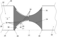
- the device comprises a fluid flow channel 22 disposed on a substrate.
- the fluid flow channel 22 is defined by a first wall 24 , a second wall 26 spaced from the first wall 24 , a fluid inlet 28 , and a fluid outlet 32 .
- the fluid flow D is from the fluid inlet 28 to the fluid outlet 32 .
- the first wall 24 includes an insulating flow structure 34 extending toward the second wall 26 thereby defining a constriction in the fluid flow channel 22 between the first wall 24 and the second wall 26 .
- the insulating flow structure 34 comprises a base section 36 and a plurality of projections 38 extending from the base section 36 toward the second wall 26 .
- the device includes electrodes in electrical communication with the fluid inlet 28 and the fluid outlet 32 of the fluid flow channel 22 , wherein the electrodes are positioned to generate a spatially non-uniform electric field across the insulating flow structure of the fluid flow channel to exert a dielectrophoretic force on particles suspended in the fluid within the fluid flow chamber.
- the device includes a power supply connected to each of the electrodes to generate an electric field within the fluid flow channel 22 .
- the second wall 26 includes a second insulating flow structure 35 having the same structure as the insulating flow structure 34 . However, the second insulating flow structure may have a different configuration from the insulating flow structure 34 .
- each projection 38 has a first end at a first junction 42 with the base section 36 and a second end at a second junction 44 with the base section 36 .
- a length L 1 from the first end to the second end can be in the range of 50 nm to 100 ⁇ m.
- the base section 36 extends from an upstream junction 46 with the first wall to a downstream junction 48 with the first wall, and the projections 38 only extend from the base section over a portion of a distance L 2 from the upstream junction 46 to the downstream junction 48 .
- the projections may only extend from the base section 36 over one half or more/less of the distance L 2 from the upstream junction 46 to the downstream junction 48 .
- a location or portion is upstream if it is situated in relation to a reference point in the opposite direction from that in which the fluid flows, whereas a location or portion is downstream if it is situated in relation to the reference point in the direction in which the fluid flows.
- the base section is elliptically shaped and the projections are elliptically shaped.
- the fluid flow channel is a microchannel.
- the analyte is a cell, in some instances a human cell, and in other instances a bacterial cell.
- the analyte is a microorganism.
- the analyte is a protein.
- the analyte is a crystal.
- the analyte is a virus.
- the device provides improved particle streamlines.
- the device provides enhanced analyte separation and improved resolution.
- the device reduces or eliminates extraneous trapping zones.
- the device provides a high ⁇
- the invention provides a multi-length scale structure for use in an insulator-based dielectrophoresis device for separating an analyte from a fluid, the device including a fluid flow channel disposed on a substrate, the fluid flow channel being defined by a first wall, and a second wall spaced from the first wall.
- the multi-length scale structure comprises an insulating flow structure extending from the first wall toward the second wall thereby defining a constriction in the fluid flow channel between the first wall and the second wall, the insulating flow structure comprising a base section and a plurality of projections extending from the base section toward the second wall.
- the base section is elliptically shaped and the projections are elliptically shaped.
- each projection has a first end at a first junction with the base section and a second end at a second junction with the base section, a length from the first end to the second end being in the range of 50 nm to 100 ⁇ m.
- the base section extends from an upstream junction with the first wall to a downstream junction with the first wall, and the projections only extend from the base section over a portion of a distance from the upstream junction to the downstream junction. In some embodiments of the multi-length scale structure, the projections only extend from the base section over one half or less of the distance from the upstream junction to the downstream junction. In some embodiments of the multi-length scale structure, the projections extend from the base section over more than half of the distance from the upstream junction to the downstream junction.
- the second wall of the multi-length scale structure may include a second insulating flow structure having the same structure as the insulating flow structure on the first wall. However, the second insulating flow structure may have a different configuration from the insulating flow structure on the first wall.
- the invention provides a method of separating a first analyte from a second analyte.
- the method comprises (a) providing the device described herein; and (b) transporting a fluid including the first analyte and the second analyte from the fluid inlet through the constriction in the fluid flow channel toward the fluid outlet.
- the methods and devices described herein can be used to separate at least one analyte, and in many embodiments, can separate one or more analytes, including any number of analytes.
- the methods and devices can separate two or more analytes, three or more analytes, four or more analytes, five or more analytes, six or more analytes, seven or more analytes, eight or more analytes, nine or more analytes, ten or more analytes, etc.
- any number of analytes can be separated, e.g., 2, 3, 4, 5, 6, 7, 8, 9, 10, 15, 20, 25, 30, 35, 40, 45, 50 etc.
- any number of analytes can be separated, especially in systems used in tandem or loop with a variable voltage.
- This example describes the development of a novel insulator geometry to improve the separation capabilities of iDEP.
- a new multi-length scale insulator has been developed.
- the insulator design will streamline the particles, minimize the possibility for extraneous trapping zones, laterally homogenize the forces, while maintaining high gradients to allow for separation.
- EK electrokinetic velocity
- DEP dielectrophoretic mobility
- DEP DEP ⁇
- DEP DEP ⁇
- DEP 2 ⁇ m r 3 f CM ⁇
- DEP is the DEP force
- ⁇ m is the permittivity of the medium
- r is the radius of the particle
- f CM is the Clausius-Mossotti factor which is dependent on the conductivity of the particle and medium in DC fields.
- the particle of interest will either undergo positive or negative DEP.
- positive DEP the conductivity of the particle is greater than the conductivity of the media; meaning that the particle is attracted to areas of high electric field.
- negative DEP the conductivity of the media is larger than that of the particle so the particle is effectively repelled from the locations of high electric field strength.
- EK and DEP result in extremely complex systems, however the behavior can be classified as either streaming or trapping behaviors. Trapping behaviors occur when the interaction between the and the slope of
- the gate pitches were 36.37 ⁇ m and 34.10 ⁇ m ( FIG. 3 ).
- the gate pitches were chosen to mimic measurements for a current channel design.
- the current channel measurements have been used for the manipulation and separation of several analytes including: polystyrene spheres, red blood cells, different serotypes of Escherichia coli , and different strains of Staphylococcus epidermidis. 1,8,11,38
- the channels modeled ranged in length from 7.5-12 mm (only the Inverse 20 ⁇ Curve channels were on the upper end of this).
- the length of the channel can be longer or shorter than 7.5-12 mm depending on the other parameters selected.
- a 500 V potential was applied so that the inlet wall was a ground and the outlet wall carried the potential ( FIG. 3 ).
- AutoCAD 2014 Autodesk, Inc, San Rafael, Calif. was used to build the to-scale microchannels.
- Insulator geometries were modeled to determine their effects on the applied electric potential.
- the insulator geometries focused on the following features: the effect of sharp features (triangular shape), flat designs (Inverse 20 ⁇ Curve and rectangular insulators), rounded insulators (circular and elliptical shapes), and the addition of small insulator features to larger geometry elements near or at the point of highest constriction ( FIG. 4 ).
- sharp features triangular shape
- flat designs Inverse 20 ⁇ Curve and rectangular insulators
- rounded insulators circular and elliptical shapes
- small insulator features to larger geometry elements near or at the point of highest constriction
- the photomask has a tolerance for the critical dimension of 0.3 ⁇ m ⁇ 10% with a maximum tolerance of 0.6 ⁇ m.
- 59 For the photomask the resolution over a 5.0 cm channel is 1.5 ⁇ m.
- Wafers were made using standard photolithographic techniques; specifically using the photoresist AZ 3312 (AZ Electronic Materials) which can be used to create features less than 0.50 ⁇ m.
- a microchannel depth of 20 ⁇ m with minimum feature size of a 2 ⁇ m is achievable using a Surface Technology Systems Deep Silicon Etch, which utilizes SF 6 , C 4 F 8 , and O 2 to etch using the Bosch process for an anisotropic etch. 61 Therefore the final multi-length scale insulator shape discussed in this example was developed with a minimum critical dimension of 2.5 ⁇ m.
- the distribution of the electric potential was modeled using the finite-element multiphysics simulation software (COMSOL Multiphysics 5.1).
- the AC/DC module was specifically used to determine the distribution of the
- the shape of insulators in iDEP is the defining attribute towards the ability to manipulate analytes within a microfluidic channel.
- the insulator induces the distribution of and therefore the ⁇
- Dielectrophoretic forces must be high enough to overcome transport and diffusional forces to generate an observable effect. This requires large gradients, resulting in large ⁇
- Sorting of particles in a continuous or semi-continuous mode has been an important use of dielectrophoresis.
- a common strategy is deflection using streaming DEP, but recent work has shown sorting by exploiting trapping or trapping-like mechanisms.
- similar principles apply, in that, all particles of a population should occupy a homogenous environment during the deflection process. This suggests that each particle is influenced by the same
- the two features can be at odds with one another, by definition gradient means a change in the value and homogeneous suggest a consistent level.
- This study probes a large variety of insulator shapes to create an environment where high gradient values are attained, while giving a homogeneous environment to all particles exposed to the separatory system.
- the most effective insulator design has sharp points, demonstrated by the triangular insulator ( FIG. 6 C ).
- the radius of curvature for sharp features changes rapidly which, in turn, constricts the electric field and results in a high ⁇
- the triangular insulator is representative of diamonds, sawteeth, and triangles used for insulators. 11,23,28,31,38,39,41
- 2 is for the 34.10 ⁇ m gate is approximated to be 3.2 ⁇ 10 16 V 2 /m 3 , which is the highest value of any of the insulator shapes examined. Particles will travel along the field line by EK forces in the absence of a significant gradient.
- Circular insulators have smaller gradients ( FIGS. 6 A&B) as the constriction of the electric field is more gradual as compared to triangular insulators. Therefore only smaller ⁇
- 2 along the centerline is 8.8 ⁇ 10 14 and 1.85 ⁇ 10 15 V 2 /m 3 for the circular and ellipse shaped insulators respectively with a gate pitch of 34.10 ⁇ m.
- Rectangular insulators are also used to alter the gradient of the electric field ( FIG. 6 D ). 14,37
- 2 along the centerline is 6.3 ⁇ 10 14 V 2 /m 3 with a gate pitch of 34.10 ⁇ m.
- the gradient for rectangular and Inverse 20 ⁇ Curve insulators ( FIGS. 6 D&F) are smaller than for circular and triangular insulators as the constriction of the electric field is abrupt, so a high gradient is limited to the corners of the insulators. These values are the lowest of any insulator shape, this could be increased by shortening the insulator or channel, however the ⁇
- 2 is not the same laterally for the triangular, circular, and rectangular insulators, so that particles will experience different forces based on their initial pathlines.
- particles starting at various vertical positions (as drawn, lateral position relative to the longitudinal axis of the device and applied external electric field) will be trapped at widely varying locations ( FIG. 1 ), meaning that trapping DEP will not occur at the same voltage for the different analyte pathlines.
- 45,46 The rectangular and Inverse 20 ⁇ Curve have the most laterally homogeneous electric field, however they do not have a strong enough gradient to trap analytes of typical interest.
- the advantage to multi-length scale design is the small insulators alter the distribution of the electric field significantly at the points approaching the constriction resulting in higher values for the ⁇
- the most useful insulator design from this study has an elliptically-shaped base insulator and small 20 ⁇ m-tall elliptically-shaped insulators across half the top of the base ( FIG. 6 E ).
- 2 at the 34.10 ⁇ m gate pitch is 1.7 ⁇ 10 15 V 2 /m 3 . This value is lower than for the triangular insulators, but higher than any of the other insulators.
- the triangular and elliptical insulator represents issues of partial trapping and an inhomogeneous lateral environment present for all other designs (circle and rectangle) and the triangular insulator has the highest ⁇
- the elliptical insulator is also used for comparison to determine the effects of the addition of the small insulators for the multi-length insulator. Using the definition of trapping in an iDEP device defined in Eq. 4 particles are trapped based on the ratio of the ⁇ EK and ⁇ DEP .
- ⁇ DEP ⁇ m ⁇ r 2 ⁇ f CM ( 12 )
- media permittivity ( ⁇ m ) is 10 ⁇ 9 F/m
- the radius of the particle (r) is 10 ⁇ 6 to 10 ⁇ 7 m
- f CM is ⁇ 0.3
- solution viscosity ( ⁇ ) is 10 ⁇ 3 Ns/m 2 . 12
- ⁇ DEP ⁇ 1.0 ⁇ 10 ⁇ 17 to ⁇ 1.0 ⁇ 10 ⁇ 19 m 4 /V 2 s. Therefore a range for the ratio of mobilities is 1.0 ⁇ 10 9 V/m 2 to 1.0 ⁇ 10 11 V/m 2 .
- a ratio of 5.6 ⁇ 10 9 V/m 2 was selected for the multi-length scale design selected to show trapping behavior at a slightly narrower gate (right) and complete passage of all particles at the wider gate (left) for the multi-length scale design ( FIG. 7 F ).
- the color scale toward red is the most repelling environment and the white areas completely exclude analytes with these properties.
- the portions with color define the area accessible to this analyte. This can be observed by noting that the white area completely bridges the gap on the right gate, indicating excluded area and trapping behavior.
- FIGS. 7 A, 7 B, 7 C , & 7 D Significantly different behaviors can be deduced for the triangular and ellipse insulators.
- the electrokinetic pathlines impinge upon the gradient at an acute angle, allowing for partial trapping at wider gates ( FIGS. 7 B & 7 D ).
- the pathlines clearly impinge on the slope of the
- the forces are more uniform laterally with the multi-length scale insulator meaning that the particles will be repelled or deflected in more a similar manner. These will ultimately lead to higher resolution separations as particles are deflected the same amount and better streaming will occur as the particles will be confined to a smaller area in the channel than with the other designs.
- the development of a new multi-length scale insulator for iDEP will allow for improved separations for both deflection and trapping techniques.
- the new insulator will streamline the analytes to ensure that like-particles experience similar environments as the is more homogenous in the accessible area. Furthermore, the minimization of partial and extraneous trapping should be possible. This can all be accomplished while maintaining
- the development of a new multi-length scale insulator for iDEP will allow for improved separations for both deflection and trapping techniques.
- the new insulator will streamline the analytes to ensure that like-particles experience similar environments as the E is more homogenous in the accessible area. Furthermore, the minimization of partial and extraneous trapping should be possible. This can all be accomplished while maintaining
Landscapes
- Chemical & Material Sciences (AREA)
- Health & Medical Sciences (AREA)
- Life Sciences & Earth Sciences (AREA)
- General Health & Medical Sciences (AREA)
- Molecular Biology (AREA)
- Analytical Chemistry (AREA)
- Chemical Kinetics & Catalysis (AREA)
- Dispersion Chemistry (AREA)
- Physics & Mathematics (AREA)
- Biochemistry (AREA)
- General Physics & Mathematics (AREA)
- Immunology (AREA)
- Pathology (AREA)
- Electrochemistry (AREA)
- Engineering & Computer Science (AREA)
- Microelectronics & Electronic Packaging (AREA)
- Clinical Laboratory Science (AREA)
- Hematology (AREA)
- Apparatus Associated With Microorganisms And Enzymes (AREA)
- Electrostatic Separation (AREA)
Abstract
Description
-
- (a) providing the device described herein;
- (b) transporting a fluid including the first analyte and the second analyte from the fluid inlet through the constriction in the fluid flow channel toward the fluid outlet.
Electric field lines present in all panels. At low
values, electric field lines are the pathlines of particles. Panels showing triangular insulator (A & B) show electric field lines off the centerline impinging the slope of the
(local direction of dielectrophoretic forces) at highly acute angles, creating a local trapping point. These lateral trapping areas are present at all sharp features and some rounded features (B & D). In this study, for the triangular and ellipse insulator given the analyte μEK/μDEP ratio of choice, the analyte is partially trapped at the first gate and fully trapped at the second gate. In contrast, the critical particle would pass the first gate completely and be trapped at the second gate for the multi-length scale insulator. Further, the multi-length scale insulator does not exhibit any lateral traps were the electric field lines impinge the
slope at extremely acute angles. The gate pitches are 36.37 μm and 34.10 μm, left to right (A-F).
The DEP velocity,
DEP is the force that is exerted on a polarizable spherical particle present in a non-uniform electric field.53,56
where
where D is the diffusion coefficient, C is the particle concentration, and
(μEK
Eq. 7 can be rearranged such that dielectrophoretic trapping is described as:58
meet at highly acute angles. Streaming DEP occurs where the
interact at glancing angles.
Microchannel Geometries
∇2φ=0 (7)
φ=V inlet (9)
φ=V outlet (10)
where
Results and Discussion
value at each point in the process.
where media permittivity (εm) is 10−9 F/m, the radius of the particle (r) is 10−6 to 10−7 m, fCM is −0.3, and solution viscosity (η) is 10−3 Ns/m2.12 This gives a range for μDEP of −1.0×10⁻¹⁷ to −1.0×10⁻¹⁹ m4/V2s. Therefore a range for the ratio of mobilities is 1.0×10⁹V/m2 to 1.0×10¹¹ V/m2. These values reasonably coincides with the value determined for Staphylococcus epidermidis of 4.6±0.6×10⁹V/m2 for gentamicin resistant and 9.2±0.4×10⁹ V/m2 for gentamicin sensitive.11
within the three designs provides evidence for significantly different behaviors (
values depicts that a triangular insulator achieves the highest values followed by the multi-length scale and then elliptical insulator (
value is plotted showing effect on a particle with a various mobility ratios. Specific ratios were utilized as the various shapes with the same constrictions and voltage applied will trap particles with ratios between 5.4×10⁹ and 1.7×10¹⁰ V/m2 (
at an acute angle. When full trapping across the gate occurs, an arc forms represented by the left edge of the white areas (
impinges upon the electrokinetic lines at a glancing angles and simply streams particles that experience negative DEP toward the centerline. For the left larger gate particles not on the centerline will impinge upon the white space (inaccessible area) first and be deflected towards the centerline, as this does not occur at highly acute angles necessary for trapping. As the particles interact with an inaccessible area first, and are deflected towards the centerline they will not interrogate the local minima between the small insulators (
At a trapping location (
values high enough to accomplish trapping.
values high enough to accomplish trapping.
- [1] Jones, P. V., Staton, S. J. R., Hayes, M. A., Anal. Bioanal. Chem. 2011, 401, 2103-2111.
- [2] Luo, J., Abdallah, B. G., Wolken, G. G., Arriaga, E. A., Ros, A., Biomgb 2014, 8, 021801.
- [3] Staton, S. J. R., Jones, P. V., Ku, G., Gilman, S. D., Kheterpal, I., Hayes, M. A., Analyst 2012, 137, 3227-3229.
- [4] Nakano, A., Camacho-Alanis, F., Ros, A., Analyst 2015, 140, 860-868.
- [5] Washizu, M., Kurosawa, O., IEEE T. Ind. Appl. 1990, 26, 1165-1172.
- [6] Chou, C.-F., Tegenfeldt, J. O., Bakajin, O., Chan, S. S., Cox, E. C., Darnton, N., Duke, T., Austin, R. H., Biophys. J. 2002, 83, 2170-2179.
- [7] Martinez-Duarte, R., Camacho-Alanis, F., Renaud, P., Ros, A.,
Electrophoresis 2013, 34, 1113-1122. - [8] Jones, P. V., DeMichele, A. F., Kemp, L., Hayes, M. A., Anal. Bioanal. Chem. 2014, 406, 183-192.
- [9] Lapizco-Encinas, B. H., Simmons, B. A., Cummings, E. B., Fintschenko, Y., Anal. Chem. 2004, 76, 1571-1579.
- [10] Lapizco-Encinas, B. H., Simmons, B. A., Cummings, E. B., Fintschenko, Y., Electrophoresis 2004, 25, 1695-1704.
- [11] Jones, P. V., Hilton, S. H., Davis, P. E., Yanashima, R., McLemore, R., McLaren, A., Hayes, M. A., Analyst 2015, 140, 5152-5161.
- [12] Jones, P. V., Hayes, M. A.,
Electrophoresis 2015, 36, 1098-1106. - [13] Abdallah, B. G., Chao, T.-C., Kupitz, C., Fromme, P., Ros, A., ACS Nano 2013, 7, 9129-9137.
- [14] Srivastava, S. K., Baylon-Cardiel, J. L., Lapizco-Encinas, B. H., Minerick, A. R., J. Chromatogr. A 2011, 1218, 1780-1789.
- [15] Hughes, M. P., Morgan, H., Rixon, F. J., Burt, J. P. H., Pethig, R., BBA-Gen Subjects 1998, 1425, 119-126.
- [16] Crane, J. S., Pohl, H. A., J. Electrochem. Soc. 1968, 115, 584-586.
- [17] Pohl, H. A., Crane, J. S., Biophys. J. 1971, 11, 711-727.
- [18] Hoettges, K. F., Hughes, M. P., Cotton, A., Hopkins, N. A. E., McDonnell, M. B., IEEE Eng. Med. Bio. 2003, 22, 68-74.
- [19] Johari, J., Hübner, Y., Hull, J. C., Dale, J. W., Hughes, M. P., Phys. Med. Biol. 2003, 48, N193.
- [20] Morgan, H., Hughes, M. P., Green, N. G., Biophys. J. 1998, 77, 516-525.
- [21] Hughes, M. P., Morgan, H., Anal. Chem. 1999, 71, 3441-3445.
- [22] Hughes, M. P., Electrophoresis 2002, 23, 2569-2582.
- [23] Chen, K. P., Pacheco, J. R., Hayes, M. A., Staton, S. J. R., Electrophoresis 2009, 30, 1441-1448.
- [24] Chaurey, V., Polanco, C., Chou, C.-F., Swami, N. S., Biomicrofluidics 2012, 6, 012806.
- [25] Swami, N., Chou, C.-F., Ramamurthy, V., Chaurey, V., Lab Chip 2009, 9, 3212-3220.
- [26] Su, Y.-H., Tsegaye, M., Varhue, W., Liao, K.-T., Abebe, L. S., Smith, J. A., Guerrant, R. L., Swami, N. S., Analyst 2014, 139, 66-73.
- [27] Gencoglu, A., Camacho-Alanis, F., Nguyen, V. T., Nakano, A., Ros, A., Minerick, A. R.,
Electrophoresis 2011, 32, 2436-2447. - [28] Cummings, E. B., Singh, A. K., Anal. Chem. 2003, 75, 4724-4731.
- [29] Srivastava, S., Gencoglu, A., Minerick, A., Anal. Bioanal. Chem. 2011, 399, 301-321.
- [30] Keshavamurthy, S. S., Leonard, K. M., Burgess, S. C., Minerick, A. R., NSTI-Nanotech, Boston, Mass. 2008, 401-404.
- [31] Kang, Y., Li, D., Kalams, S., Eid, J., Biomed. Microdevices 2008, 10, 243-249.
- [32] Barbulovic-Nad, I., Xuan, X., Lee, J. S. H., Li, D., Lab Chip 2006, 6, 274-279.
- [33] Thwar, P. K., Linderman, J. J., Burns, M. A.,
Electrophoresis 2007, 28, 4572-4581. - [34] Lapizco-Encinas, B. H., Davalos, R. V., Simmons, B. A., Cummings, E. B., Fintschenko, Y., J. Microbiol. Methods 2005, 62, 317-326.
- [35] Sabounchi, P., Morales, A., Ponce, P., Lee, L., Simmons, B., Davalos, R., Biomed. Microdevices 2008, 10, 661-670.
- [36] Regtmeier, J., Duong, T. T., Eichhorn, R., Anselmetti, D., Ros, A., Anal. Chem. 2007, 79, 3925-3932.
- [37] Kang, K. H., Kang, Y., Xuan, X., Li, D., Electrophoresis 2006, 27, 694-702.
- [38] Staton, S. J. R., Chen, K. P., Taylor, T. J., Pacheco, J. R., Hayes, M. A., Electrophoresis 2010, 31, 3634-3641.
- [39] Pysher, M. D., Hayes, M. A., Anal. Chem. 2007, 79, 4552-4557.
- [40] Gallo-Villanueva, R. C., Rodríguez-López, C. E., Díaz-de-la-Garza, R. I., Reyes-Betanzo, C., Lapizco-Encinas, B. H., Electrophoresis 2009, 30, 4195-4205.
- [41] LaLonde, A., Gencoglu, A., Romero-Creel, M. F., Koppula, K. S., Lapizco-Encinas, B. H., Journal of Chromatogr. A 2014, 1344, 99-108.
- [42] Cummings, E. B., IEEE Eng. Med. Bio. 2003, 22, 75-84.
- [43] Srivastava, S. K., Artemiou, A., Minerick, A. R.,
Electrophoresis 2011, 32, 2530-2540. - [44] Abdallah, B. G., Roy-Chowdhury, S., Coe, J., Fromme, P., Ros, A., Anal. Chem. 2015, 87, 4159-4167.
- [45] Gallo-Villanueva, R. C., Sano, M. B., Lapizco-Encinas, B. H., Davalos, R. V.,
Electrophoresis 2014, 35, 352-361. - [46] Saucedo-Espinosa, M. A., Lapizco-Encinas, B. H.,
Electrophoresis 2015, 36, 1086-1097. - [47] Giddings, J. C., Unified Separation Science, John Wiley & Sons, Inc., New York 1991.
- [48] Morton, K. J., Loutherback, K., Inglis, D. W., Tsui, O. K., Sturm, J. C., Chou, S. Y., Austin, R. H., P. Natl. Acad. Sci. USA 2008, 105, 7434-7438.
- [49] Huang, L. R., Cox, E. C., Austin, R. H., Sturm, J. C., Science 2004, 304, 987-990.
- [50] Streek, M., Schmid, F., Duong, T. T., Ros, A., J. Biotech. 2004, 112, 79-89.
- [51] Ros, A., Hellmich, W., Regtmeier, J., Duong, T. T., Anselmetti, D., Electrophoresis 2006, 27, 2651-2658.
- [52] Ozuna-Chacón, S., Lapizco-Encinas, B. H., Rito-Palomares, M., Martinez-Chapa, S. O., Reyes-Betanzo, C., Electrophoresis 2008, 29, 3115-3122.
- [53] Pohl, H. A., Dielectrophoresis: the behavior of neutral matter in nonuniform electric fields, Cambridge University Press, Cambridge; New York 1978.
- [54] Pethig, R., Biomicrofluidics 2010, 4, 022811.
- [55] Probstein, R. F., Physicochemical Hydrodynamics: An Introduction, John Wiley & Sons, Inc. 1994, pp. 1-8.
- [56] Jones, T. B., Electromechanics of Particles, Cambridge University Press 1995.
- [57] Kwon, J.-S., Maeng, J.-S., Chun, M.-S., Song, S., Microfluid Nanofluidics 2008, 5, 23-31.
- [58] Baylon-Cardiel, J. L., Lapizco-Encinas, B. H., Reyes-Betanzo, C., Chavez-Santoscoy, A. V., Martinez-Chapa, S. O., Lab Chip 2009, 9, 2896-2901.
- [59] Dingley, J., in: Photo-Tools, J. (Ed.), JD Photo-Tools 2014, pp. 1-89.
- [60 AZ Electronic Materials: AZ® 3300 Series Crossover Photoresists 2005.
- [61] Bhardwaj, J., Ashraf, H., McQuarrie, A., Proc. Symp. Microstructures and Microfabricated Systems, ECS 1997.
- [62]. Shalliker, R. A., Broyles, B. S., Guiochon, G., J. Chromatogr. A. 2000, 888, 1-12.
- [63] Staton, S. J. R., Chen, K. P., Taylor, J. P., Pacheco, J. R., Hayes, M. A., Electrophoresis 2010, 31, 3634-3641.
- [64] Pesch, G. R., Kiewidt, L., Du, F., Baune, M., Thöming, J., Electrophoresis, 2016, 37, 291-301.
- [65] Saucedo-Espinosa, M. A., Lapizco-Encinas, B. H., J. Chromatogr. A. 2015, 36, 325-333.
Claims (16)
Priority Applications (2)
| Application Number | Priority Date | Filing Date | Title |
|---|---|---|---|
| US17/400,419 US11806729B2 (en) | 2016-08-10 | 2021-08-12 | Hyper efficient separations device |
| US18/479,220 US20240149275A1 (en) | 2016-08-10 | 2023-10-02 | Hyper Efficient Separations Device |
Applications Claiming Priority (4)
| Application Number | Priority Date | Filing Date | Title |
|---|---|---|---|
| US201662372846P | 2016-08-10 | 2016-08-10 | |
| PCT/US2017/046217 WO2018031722A1 (en) | 2016-08-10 | 2017-08-10 | Hyper efficient separations device |
| US201916324324A | 2019-02-08 | 2019-02-08 | |
| US17/400,419 US11806729B2 (en) | 2016-08-10 | 2021-08-12 | Hyper efficient separations device |
Related Parent Applications (2)
| Application Number | Title | Priority Date | Filing Date |
|---|---|---|---|
| US16/324,324 Division US11090660B2 (en) | 2016-08-10 | 2017-08-10 | Hyper efficient separations device |
| PCT/US2017/046217 Division WO2018031722A1 (en) | 2016-08-10 | 2017-08-10 | Hyper efficient separations device |
Related Child Applications (1)
| Application Number | Title | Priority Date | Filing Date |
|---|---|---|---|
| US18/479,220 Continuation US20240149275A1 (en) | 2016-08-10 | 2023-10-02 | Hyper Efficient Separations Device |
Publications (2)
| Publication Number | Publication Date |
|---|---|
| US20210370319A1 US20210370319A1 (en) | 2021-12-02 |
| US11806729B2 true US11806729B2 (en) | 2023-11-07 |
Family
ID=61162514
Family Applications (3)
| Application Number | Title | Priority Date | Filing Date |
|---|---|---|---|
| US16/324,324 Active 2038-04-11 US11090660B2 (en) | 2016-08-10 | 2017-08-10 | Hyper efficient separations device |
| US17/400,419 Active 2037-09-15 US11806729B2 (en) | 2016-08-10 | 2021-08-12 | Hyper efficient separations device |
| US18/479,220 Pending US20240149275A1 (en) | 2016-08-10 | 2023-10-02 | Hyper Efficient Separations Device |
Family Applications Before (1)
| Application Number | Title | Priority Date | Filing Date |
|---|---|---|---|
| US16/324,324 Active 2038-04-11 US11090660B2 (en) | 2016-08-10 | 2017-08-10 | Hyper efficient separations device |
Family Applications After (1)
| Application Number | Title | Priority Date | Filing Date |
|---|---|---|---|
| US18/479,220 Pending US20240149275A1 (en) | 2016-08-10 | 2023-10-02 | Hyper Efficient Separations Device |
Country Status (4)
| Country | Link |
|---|---|
| US (3) | US11090660B2 (en) |
| EP (1) | EP3529604B1 (en) |
| CA (1) | CA3033518A1 (en) |
| WO (1) | WO2018031722A1 (en) |
Families Citing this family (5)
| Publication number | Priority date | Publication date | Assignee | Title |
|---|---|---|---|---|
| CN112005278A (en) * | 2018-04-27 | 2020-11-27 | 惠普发展公司,有限责任合伙企业 | Non-rotating non-uniform electric field object rotation |
| JP7057728B2 (en) * | 2018-07-13 | 2022-04-20 | 浜松ホトニクス株式会社 | Electrophoretic method, electrophoresis system, and storage container for electrophoresis |
| JP7515391B2 (en) * | 2020-12-14 | 2024-07-12 | 浜松ホトニクス株式会社 | Method and device for capturing fine particles |
| US12208400B2 (en) | 2021-05-25 | 2025-01-28 | Arizona Board Of Regents On Behalf Of Arizona State University | Systems and methods for non-destructive isolation, concentration, and detection for unbiased characterization of nano- and bioparticles |
| CN120976025B (en) * | 2025-10-21 | 2026-01-06 | 湖州市农业科学研究院(湖州市农业科技发展中心) | A super-resolution image reconstruction method oriented towards hyphal topology |
Citations (22)
| Publication number | Priority date | Publication date | Assignee | Title |
|---|---|---|---|---|
| WO1999045377A1 (en) | 1998-03-04 | 1999-09-10 | Arizona Board Of Regents | Chemical surface for control of electroosmosis by an applied external voltage field |
| WO1999064851A1 (en) | 1998-06-11 | 1999-12-16 | Arizona Board Of Regents | Control of flow and materials for micro devices |
| WO2000028315A1 (en) | 1998-11-12 | 2000-05-18 | Arizona Board Of Regents | Practical device for controlling ultrasmall volume flow |
| US20010023825A1 (en) * | 1999-05-28 | 2001-09-27 | Leonid Frumin | Methods and apparatus for nonlinear mobility electrophoresis separation |
| WO2001089985A2 (en) | 2000-05-23 | 2001-11-29 | Arizona Board Of Regents | Novel method of creating micro-structures for micro-fluidic applications |
| WO2001098785A2 (en) | 2000-06-19 | 2001-12-27 | Arizona Board Of Regents | Rapid flow-based immunoassay microchip |
| US20030042140A1 (en) | 2000-08-30 | 2003-03-06 | Arizona Board Of Regents | Chemical furface for control of electroosmosis by an applied external voltage field |
| WO2004081536A2 (en) | 2003-03-12 | 2004-09-23 | Arizona Board Of Regents | Radical activated cleavage of biologics and microfluidic devices using the same |
| US6890411B1 (en) | 1998-06-11 | 2005-05-10 | Arizona Board Of Regents | Control of flow and materials for micro devices |
| US20070054316A1 (en) | 2003-01-16 | 2007-03-08 | Wiener Robert J | Radical activated cleavage of biologics and microfluidic devices using the same |
| WO2007101174A2 (en) | 2006-02-27 | 2007-09-07 | Arizona Board Of Regents For And On Behalf Of Arizona State University | Digital magnetofluidic devices and methods |
| US20070284254A1 (en) | 2006-05-29 | 2007-12-13 | Samsung Electronics Co., Ltd. | Apparatus for and method of separating polarizable analyte using dielectrophoresis |
| US20080213853A1 (en) | 2006-02-27 | 2008-09-04 | Antonio Garcia | Magnetofluidics |
| WO2008124693A1 (en) | 2007-04-05 | 2008-10-16 | The Arizona Board Of Regents, A Body Corporate Of The State Of Arizona Acting For And On Behalf Of Arizona State University | Separation-based arrays |
| WO2009009028A1 (en) | 2007-07-06 | 2009-01-15 | Hayes Mark A | System and method for automated bioparticle recognition |
| US20110174623A1 (en) | 2001-05-02 | 2011-07-21 | Applied Biosystems, Llc | Concentration and Purification of Analytes Using Electric Fields |
| WO2013148166A1 (en) | 2012-03-29 | 2013-10-03 | Arizona Board Of Regents, A Body Corporate Of The State Of Arizona, Acting For And On Behlaf Of Arizona State University | Nanoscale process to generate reagents selective for individual protein variants |
| US20130286183A1 (en) | 2012-04-25 | 2013-10-31 | Arizona Board of Regents, A Body Corporate of the State of Arizona, Acting For and On Behalf of Arizona Stat | Bacterial identification |
| US20140091012A1 (en) | 2012-09-30 | 2014-04-03 | Arizona Board of Regents, a body Corporate of the State of Arizona, Acting for and on Behalf of Ariz | Methods, Systems and Apparatus for Size-Based Particle Separation |
| US20140131204A1 (en) | 2012-11-13 | 2014-05-15 | Academia Sinica | Molecular entrapment and enrichment |
| WO2014121226A2 (en) | 2013-02-01 | 2014-08-07 | Arizona Board of Regents, a body corporate of the State of Arizona Acting for and on behalf of Arizo | Punctuated microgradients for improved separations of molecules and particles |
| WO2016057974A1 (en) | 2014-10-09 | 2016-04-14 | University Of Virginia Patent Foundation | Identification and monitoring of cells by dielectrophoretic tracking of electrophysiology and phenotype |
Family Cites Families (1)
| Publication number | Priority date | Publication date | Assignee | Title |
|---|---|---|---|---|
| US7678256B2 (en) * | 2006-11-03 | 2010-03-16 | Sandia Corporation | Insulator-based DEP with impedance measurements for analyte detection |
-
2017
- 2017-08-10 EP EP17840247.5A patent/EP3529604B1/en not_active Not-in-force
- 2017-08-10 US US16/324,324 patent/US11090660B2/en active Active
- 2017-08-10 WO PCT/US2017/046217 patent/WO2018031722A1/en not_active Ceased
- 2017-08-10 CA CA3033518A patent/CA3033518A1/en active Pending
-
2021
- 2021-08-12 US US17/400,419 patent/US11806729B2/en active Active
-
2023
- 2023-10-02 US US18/479,220 patent/US20240149275A1/en active Pending
Patent Citations (35)
| Publication number | Priority date | Publication date | Assignee | Title |
|---|---|---|---|---|
| US6488831B1 (en) | 1998-03-04 | 2002-12-03 | Arizona Board Of Regents Arizona State University | Chemical surface for control of electroosmosis by an applied external voltage field |
| WO1999045377A1 (en) | 1998-03-04 | 1999-09-10 | Arizona Board Of Regents | Chemical surface for control of electroosmosis by an applied external voltage field |
| WO1999064851A1 (en) | 1998-06-11 | 1999-12-16 | Arizona Board Of Regents | Control of flow and materials for micro devices |
| US6890411B1 (en) | 1998-06-11 | 2005-05-10 | Arizona Board Of Regents | Control of flow and materials for micro devices |
| WO2000028315A1 (en) | 1998-11-12 | 2000-05-18 | Arizona Board Of Regents | Practical device for controlling ultrasmall volume flow |
| WO2000028315B1 (en) | 1998-11-12 | 2000-07-06 | Univ Arizona | Practical device for controlling ultrasmall volume flow |
| US20010023825A1 (en) * | 1999-05-28 | 2001-09-27 | Leonid Frumin | Methods and apparatus for nonlinear mobility electrophoresis separation |
| US20040050435A1 (en) | 2000-05-23 | 2004-03-18 | Hayes Mark A. | Novel method of creating micro-structures for micro-fluidic applications |
| WO2001089985A2 (en) | 2000-05-23 | 2001-11-29 | Arizona Board Of Regents | Novel method of creating micro-structures for micro-fluidic applications |
| WO2001098785A3 (en) | 2000-06-19 | 2002-09-19 | Univ Arizona | Rapid flow-based immunoassay microchip |
| WO2001098785A2 (en) | 2000-06-19 | 2001-12-27 | Arizona Board Of Regents | Rapid flow-based immunoassay microchip |
| US20050032051A1 (en) | 2000-06-19 | 2005-02-10 | Hayes Mark A | Rapid flow-based immunoassay microchip |
| US20030042140A1 (en) | 2000-08-30 | 2003-03-06 | Arizona Board Of Regents | Chemical furface for control of electroosmosis by an applied external voltage field |
| US20110174623A1 (en) | 2001-05-02 | 2011-07-21 | Applied Biosystems, Llc | Concentration and Purification of Analytes Using Electric Fields |
| US20070054316A1 (en) | 2003-01-16 | 2007-03-08 | Wiener Robert J | Radical activated cleavage of biologics and microfluidic devices using the same |
| WO2004081536A2 (en) | 2003-03-12 | 2004-09-23 | Arizona Board Of Regents | Radical activated cleavage of biologics and microfluidic devices using the same |
| WO2007101174A2 (en) | 2006-02-27 | 2007-09-07 | Arizona Board Of Regents For And On Behalf Of Arizona State University | Digital magnetofluidic devices and methods |
| US20080213853A1 (en) | 2006-02-27 | 2008-09-04 | Antonio Garcia | Magnetofluidics |
| US20070284254A1 (en) | 2006-05-29 | 2007-12-13 | Samsung Electronics Co., Ltd. | Apparatus for and method of separating polarizable analyte using dielectrophoresis |
| WO2008124693A1 (en) | 2007-04-05 | 2008-10-16 | The Arizona Board Of Regents, A Body Corporate Of The State Of Arizona Acting For And On Behalf Of Arizona State University | Separation-based arrays |
| WO2009009028A1 (en) | 2007-07-06 | 2009-01-15 | Hayes Mark A | System and method for automated bioparticle recognition |
| US8821703B2 (en) | 2007-07-06 | 2014-09-02 | Mark A. Hayes | System and method for automated bioparticle recognition |
| US20140371102A1 (en) | 2007-07-06 | 2014-12-18 | Mark A. Hayes | System and method for automated bioparticle recognition |
| WO2013148166A1 (en) | 2012-03-29 | 2013-10-03 | Arizona Board Of Regents, A Body Corporate Of The State Of Arizona, Acting For And On Behlaf Of Arizona State University | Nanoscale process to generate reagents selective for individual protein variants |
| US9938330B2 (en) | 2012-03-29 | 2018-04-10 | Arizona Board Of Regents, A Body Corporate Of The State Of Arizona, Acting For And On Behalf Of Arizona State University | Nanoscale process to generate reagents selective for individual protein variants |
| US20150056638A1 (en) * | 2012-03-29 | 2015-02-26 | Arizona Board of Regents, a Body Corp. of the State of Arizona, Acting For and on Behalf of Az. | Nanoscale process to generate reagents selective for individual protein variants |
| US9185356B2 (en) | 2012-04-25 | 2015-11-10 | Arizona Board Of Regents On Behalf Of Arizona State University | Bacterial identification |
| US20130286183A1 (en) | 2012-04-25 | 2013-10-31 | Arizona Board of Regents, A Body Corporate of the State of Arizona, Acting For and On Behalf of Arizona Stat | Bacterial identification |
| US9476085B2 (en) | 2012-04-25 | 2016-10-25 | Arizona Board Of Regents On Behalf Of Arizona State University | Bacterial identification |
| US20140091012A1 (en) | 2012-09-30 | 2014-04-03 | Arizona Board of Regents, a body Corporate of the State of Arizona, Acting for and on Behalf of Ariz | Methods, Systems and Apparatus for Size-Based Particle Separation |
| US20140131204A1 (en) | 2012-11-13 | 2014-05-15 | Academia Sinica | Molecular entrapment and enrichment |
| US20150360237A1 (en) | 2013-02-01 | 2015-12-17 | Arizona Borad Of Regents On Behalf Of Arizona State University | Punctuated microgradients for improved separations of molecules and particles |
| WO2014121226A2 (en) | 2013-02-01 | 2014-08-07 | Arizona Board of Regents, a body corporate of the State of Arizona Acting for and on behalf of Arizo | Punctuated microgradients for improved separations of molecules and particles |
| US10022728B2 (en) | 2013-02-01 | 2018-07-17 | Arizona Board Of Regents On Behalf Of Arizona State University | Punctuated microgradients for improved separations of molecules and particles |
| WO2016057974A1 (en) | 2014-10-09 | 2016-04-14 | University Of Virginia Patent Foundation | Identification and monitoring of cells by dielectrophoretic tracking of electrophysiology and phenotype |
Non-Patent Citations (73)
| Title |
|---|
| Abdallah, B. G., et al. "Dielectrophoretic sorting of membrane protein nanocrystals." ACS nano 7.10 (2013): 9129-9137. |
| Abdallah, B. G., et al. "High throughput protein nanocrystal fractionation in a microfluidic sorter." Analytical chemistry 87.8 (2015): 4159-4167. |
| Allen, D. "Isomotive dielectrophoresis for parallel analysis of individual particles", Electrophoresis, Jun. 2017 [available online Jan. 2017], vol. 38, No. 11, pp. 1441-1449 DOI:10.1002/elps.201600517. |
| Barbulovic-Nad, I., et al. "DC-dielectrophoretic separation of microparticles using an oil droplet obstacle." Lab on a Chip6.2 (2006): 274-279. |
| Barrett, L. et al., "Dielectrophoretic Manipulation of Particles and Cells Using Insulating Ridges in Faceted Prism Microchannels", Analytical Chemistry, Nov. 2005 (available online Sep. 2005), vol. 77, No. 21, pp. 6798-6804 DOI:10.1021/ac0507791. |
| Baylon-Cardiel, J. L., et al. "Prediction of trapping zones in an insulator-based dielectrophoretic device." Lab on a Chip9.20 (2009): 2896-2901. |
| Bhardwaj, J., et al. "Dry silicon etching for MEMS." Proc. Symp. Microstructures and Microfabricated Systems, ECS. 1997. |
| Braff, W. et al., "Dielectrophoresis-Based Discrimination of Bacteria at the Strain Level Based on Their Surface Properties", PLOS One, Oct. 2013, vol. 8, No. 10, e76751 (DOI:10.1371/journal.pone.0076751). |
| Braff, W. et al., "High sensitivity three-dimensional insulator-based dielectrophoresis", Lab on a Chip, Feb. 2012, vol. 12, pp. 1327-1331 (DOI:10.1039/C2LC21212A). |
| Chaurey, V., et al. "Floating-electrode enhanced constriction dielectrophoresis for biomolecular trapping in physiological media of high conductivity." Biomicrofluidics 6.1 (2012): 012806. |
| Chen, K. P., et al. "Insulator-based dielectrophoretic separation of small particles in a sawtooth channel." Electrophoresis 30.9 (2009): 1441-1448. |
| Chou, C.-F., et al. "Electrodeless dielectrophoresis of single-and double-stranded DNA." Biophysical journal 83.4 (2002): 2170-2179. |
| Crane, J. S., et al. "A study of living and dead yeast cells using dielectrophoresis." Journal of the Electrochemical Society 115.6 (1968): 584-586. |
| Crowther, C. et al., "Refinement of insulator-based dielectrophoresis", Analyst, Apr. 2017, vol. 142, pp. 1608-1618 (DOI:10.1039/C6AN02509A). |
| Cummings, E. B. "Streaming dielectrophoresis for continuous-flow microfluidic devices." IEEE Engineering in Medicine and Biology Magazine 22.6 (2003): 75-84. |
| Cummings, E. B., et al. "Dielectrophoresis in microchips containing arrays of insulating posts: theoretical and experimental results." Analytical chemistry 75.18 (2003): 4724-4731. |
| Ding, J. et al., "Concentration of Sindbis virus with optimized gradient insulator-based dielectrophoresis", Analyst, Mar. 2016 [available online Feb. 2016], vol. 141, No. 6, pp. 1997-2008 (DOI:10.1039/c5an02430g). |
| European Patent Office, Extended European Search Report, Application No. 17840247.5, dated Feb. 27, 2020, 11 pages. |
| Gallo-Villanueva, R. C., et al. "DNA manipulation by means of insulator-based dielectrophoresis employing direct current electric fields." Electrophoresis 30.24 (2009): 4195-4205. |
| Gallo-Villanueva, R. C., et al. "Joule heating effects on particle immobilization in insulator-based dielectrophoretic devices." Electrophoresis 35.2-3 (2014): 352-361. |
| Gencoglu, A., "Chemical and morphological changes on platinum microelectrode surfaces in AC and DC fields with biological buffer solutions." Lab on a Chip 9.13 (2009): 1866-1873. |
| Gencoglu, A., et al. "Quantification of pH gradients and implications in insulator-based dielectrophoresis of biomolecules." Electrophoresis 32.18 (2011): 2436-2447. |
| Hoettges, K. F., et al. "Optimizing particle collection for enhanced surface-based biosensors." IEEE engineering in medicine and biology magazine 22.6 (2003): 68-74. |
| Huang, L. R., et al. "Continuous particle separation through deterministic lateral displacement." Science 304.5673 (2004): 987-990. |
| Hughes, M. P. "Strategies for dielectrophoretic separation in laboratory-on-a-chip systems." Electrophoresis 23.16 (2002): 2569-2582. |
| Hughes, M. P., et al. "Dielectrophoretic characterization and separation of antibody-coated submicrometer latex spheres." Analytical Chemistry 71.16 (1999): 3441-3445. |
| Hughes, M. P., et al. "Manipulation of herpes simplex virus type 1 by dielectrophoresis." Biochimica et Biophysica Acta (BBA)-General Subjects 1425.1 (1998): 119-126. |
| Humble, P. et al., "Electric Field Gradient Focusing of Proteins Based on Shaped Ionically Conductive Acrylic Polymer", Analytical Chemistry, Oct. 2004 [available online Aug. 2004], vol. 76, No. 19, pp. 5641-5648 (10.1021/ac040055+). |
| Integrated Micro Materials. AZ Electronic Materials: AZ® 3300 Series Crossover Photoresists 2013. |
| International Search Report and Written Opinion for application PCT/US2017/046217, dated Oct. 24, 2017. |
| Johari, J., et al. "Dielectrophoretic assay of bacterial resistance to antibiotics." Physics in Medicine & Biology 48.14 (2003): N193. |
| Jones, P. V., et al. "Biophysical separation of Staphylococcus epidermidis strains based on antibiotic resistance." Analyst 140.15 (2015): 5152-5161. |
| Jones, P. V., et al. "Blood cell capture in a sawtooth dielectrophoretic microchannel." Analytical and bioanalytical chemistry 401.7 (2011): 2103. |
| Jones, P. V., et al. "Development of the resolution theory for gradient insulator-based dielectrophoresis." Electrophoresis 36.9-10 (2015): 1098-1106. |
| Jones, P. V., et al. "Differentiation of Escherichia coli serotypes using DC gradient insulator dielectrophoresis." Analytical and bioanalytical chemistry 406.1 (2014): 183-192. |
| Kang, K. H., et al. "Continuous separation of microparticles by size with Direct current-dielectrophoresis." Electrophoresis 27.3 (2006): 694-702. |
| Kang, Y., et al. "DC-Dielectrophoretic separation of biological cells by size." Biomedical microdevices 10.2 (2008): 243-249. |
| Keshavamurthy, S. S., et al. "Direct current dielectrophoretic characterization of erythrocytes: Positive ABO blood types." NSTI-Nanotech, Boston, MA (2008): 401-404. |
| Kwon, J.-S., et al. "Improvement of microchannel geometry subject to electrokinesis and dielectrophoresis using numerical simulations." Microfluidics and Nanofluidics 5.1 (2008): 23-31. |
| Lalonde, A., et al. "Effect of insulating posts geometry on particle manipulation in insulator based dielectrophoretic devices." Journal of Chromatography A 1344 (2014): 99-108. |
| Lapizco-Encinas, B. H., et al. "An insulator-based (electrodeless) dielectrophoretic concentrator for microbes in water." Journal of Microbiological methods 62.3 (2005): 317-326. |
| Lapizco-Encinas, B. H., et al. "Dielectrophoretic concentration and separation of live and dead bacteria in an array of insulators." Analytical chemistry 76.6 (2004): 1571-1579. |
| Lapizco-Encinas, B. H., et al. "Insulator-based dielectrophoresis for the selective concentration and separation of live bacteria in water." Electrophoresis 25.10-11 (2004): 1695-1704. |
| Luo, J., et al. "Insulator-based dielectrophoresis of mitochondria." Biomicrofluidics 8.2 (2014): 021801. |
| Martinez-Duarte, R., et al. "Dielectrophoresis of lambda-DNA using 3D carbon electrodes." Electrophoresis 34.7 (2013): 1113-1122. |
| Morgan, H., et al. "Separation of submicron bioparticles by dielectrophoresis." Biophysical journal 77.1 (1999): 516-525. |
| Morton, K. J., et al. "Hydrodynamic metamaterials: Microfabricated arrays to steer, refract, and focus streams of biomaterials." Proceedings of the National Academy of Sciences 105.21 (2008): 7434-7438. |
| Nakano, A. et al. "Insulator-based dielectrophoresis with ß-galactosidase in nanostructured devices." Analyst 140.3 (2015): 860-868. |
| Ozuna-Chacón, S., et al. "Performance characterization of an insulator-based dielectrophoretic microdevice." Electrophoresis 29.15 (2008): 3115-3122. |
| Pesch, G. R., et al. "Electrodeless dielectrophoresis: Impact of geometry and material on obstacle polarization." Electrophoresis 37.2 (2016): 291-301. |
| Pethig, R.. "Dielectrophoresis: Status of the theory, technology, and applications." Biomicrofluidics 4.2 (2010): 022811. |
| Pohl, H. A. "The motion and precipitation of suspensoids in divergent electric fields." Journal of Applied Physics 22.7 (1951): 869-871. |
| Pohl, H. A., et al. "Dielectrophoresis of cells." Biophysical journal 11.9 (1971): 711-727. |
| Probstein, R. F., Physicochemical Hydrodynamics: An Introduction, John Wiley & Sons, Inc. 1994, pp. 1-8. |
| Pysher, M. D., et al. "Electrophoretic and dielectrophoretic field gradient technique for separating bioparticles." Analytical chemistry 79.12 (2007): 4552-4557. |
| Regtmeier, J., et al. "Dielectrophoretic manipulation of DNA: separation and polarizability." Analytical chemistry 79.10 (2007): 3925-3932. |
| Ros, A., et al. "Bioanalysis in structured microfluidic systems." Electrophoresis 27.13 (2006): 2651-2658. |
| Sabounchi, P., et al. "Sample concentration and impedance detection on a microfluidic polymer chip." Biomedical Microdevices 10.5 (2008): 661. |
| Saucedo-Espinosa, M. A., et al. "Design of insulator-based dielectrophoretic devices: Effect of insulator posts characteristics." Journal of Chromatography A 1422 (2015): 325-333. |
| Saucedo-Espinosa, M. A., et al. "Experimental and theoretical study of dielectrophoretic particle trapping in arrays of insulating structures: Effect of particle size and shape." Electrophoresis 36.9-10 (2015): 1086-1097. |
| Shalliker, R. A., et al. "Physical evidence of two wall effects in liquid chromatography." Journal of Chromatography A 888.1-2 (2000): 1-12. |
| Srivastava, S. K., et al. "A continuous DC-insulator dielectrophoretic sorter of microparticles." Journal of Chromatography A 1218.13 (2011): 1780-1789. |
| Srivastava, S. K., et al. "DC insulator dielectrophoretic applications in microdevice technology: a review." Analytical and bioanalytical chemistry 399.1 (2011): 301-321. |
| Srivastava, S. K., et al. "Direct current insulator-based dielectrophoretic characterization of erythrocytes: ABO-Rh human blood typing." Electrophoresis 32.18 (2011): 2530-2540. |
| Staton, SJR, et al. "Characterization of particle capture in a sawtooth patterned insulating electrokinetic microfluidic device." Electrophoresis 31.22 (2010): 3634-3641. |
| Staton, SJR, et al. "Manipulation and capture of Aß amyloid fibrils and monomers by DC insulator gradient dielectrophoresis (DC-iGDEP)." Analyst 137.14 (2012): 3227-3229. |
| Streek, M., et al. "Mechanisms of DNA separation in entropic trap arrays: a Brownian dynamics simulation." Journal of biotechnology 112.1-2 (2004): 79-89. |
| Su, Y.-H., et al. "Quantitative dielectrophoretic tracking for characterization and separation of persistent subpopulations of Cryptosporidium parvum." Analyst 139.1 (2014): 66-73. |
| Swami, N., et al. "Enhancing DNA hybridization kinetics through constriction-based dielectrophoresis." Lab on a Chip9.22 (2009): 3212-3220. |
| Thwar, P. K., et al. "Electrodeless direct current dielectrophoresis using reconfigurable field-shaping oil barriers." Electrophoresis28.24 (2007): 4572-4581. |
| Washizu, M. et al. "Electrostatic manipulation of DNA in microfabricated structures." IEEE Transactions on industry applications 26.6 (1990): 1165-1172. |
| Weiss, N. et al., "Dielectrophoretic mobility determination in DC insulator-based dielectrophoresis", Electrophoresis, Sep. 2011 [available online Aug. 2011]. vol. 32, No. 17, pp. 2292-2297 (DOI:10.1002/elps.201100034). |
| Zellner, P. et al., "3D Insulator-based dielectrophoresis using DC-biased, AC electric fields for selective bacterial trapping", Electrophoresis, Jan. 2015 [available online Sep. 2014], vol. 36, No. 2, pp. 277-283 (DOI:10.1002/elps.201400236). |
Also Published As
| Publication number | Publication date |
|---|---|
| EP3529604B1 (en) | 2022-05-25 |
| US11090660B2 (en) | 2021-08-17 |
| EP3529604A1 (en) | 2019-08-28 |
| US20240149275A1 (en) | 2024-05-09 |
| CA3033518A1 (en) | 2018-02-15 |
| US20210370319A1 (en) | 2021-12-02 |
| US20190168237A1 (en) | 2019-06-06 |
| EP3529604A4 (en) | 2020-04-01 |
| WO2018031722A1 (en) | 2018-02-15 |
Similar Documents
| Publication | Publication Date | Title |
|---|---|---|
| US11806729B2 (en) | Hyper efficient separations device | |
| Crowther et al. | Refinement of insulator-based dielectrophoresis | |
| Saucedo‐Espinosa et al. | Experimental and theoretical study of dielectrophoretic particle trapping in arrays of insulating structures: Effect of particle size and shape | |
| Xuan | Recent advances in direct current electrokinetic manipulation of particles for microfluidic applications | |
| Nakano et al. | Immunoglobulin G and bovine serum albumin streaming dielectrophoresis in a microfluidic device | |
| US6596143B1 (en) | Apparatus for switching and manipulating particles and method of use thereof | |
| Barbulovic-Nad et al. | DC-dielectrophoretic separation of microparticles using an oil droplet obstacle | |
| Zhao et al. | Continuous separation of nanoparticles by type via localized DC-dielectrophoresis using asymmetric nano-orifice in pressure-driven flow | |
| Nakano et al. | Insulator-based dielectrophoresis with β-galactosidase in nanostructured devices | |
| Kang et al. | Electrokinetic motion of particles and cells in microchannels | |
| US11944967B2 (en) | Deterministic ratchet for sub-micrometer bioparticle separation | |
| Sonker et al. | Separation phenomena in tailored micro-and nanofluidic environments | |
| Thwar et al. | Electrodeless direct current dielectrophoresis using reconfigurable field‐shaping oil barriers | |
| Camacho-Alanis et al. | Transitioning streaming to trapping in DC insulator-based dielectrophoresis for biomolecules | |
| KR100624460B1 (en) | Microfluidic device comprising a membrane having nano to micro size pores formed thereon and a method for separating polarizable material using the same | |
| Saucedo-Espinosa et al. | Design of insulator-based dielectrophoretic devices: Effect of insulator posts characteristics | |
| Li et al. | Continuous manipulation and separation of particles using combined obstacle‐and curvature‐induced direct current dielectrophoresis | |
| Bhattacharya et al. | Insulator‐based dielectrophoretic single particle and single cancer cell trapping | |
| Rashed et al. | Advances and applications of isomotive dielectrophoresis for cell analysis | |
| Ivory et al. | Direct current dielectrophoretic simulation of proteins using an array of circular insulating posts | |
| US20070084727A1 (en) | Coherent nonlinear chromatography and methods and devices thereof | |
| Zhang | Investigation of dielectrophoresis and its applications in micro/nano fluidics, electronics and fabrications | |
| Hemmatifar et al. | Continuous size-based focusing and bifurcating microparticle streams using a negative dielectrophoretic system | |
| Duschl et al. | Versatile chip-based tool for the controlled manipulation of microparticles in biology using high Frequency Electromagnetic Fields | |
| Zhao | Nano-orifice based Dielectrophoretic Manipulation and Characterization of Nanoparticles and Biological Cells |
Legal Events
| Date | Code | Title | Description |
|---|---|---|---|
| FEPP | Fee payment procedure |
Free format text: ENTITY STATUS SET TO UNDISCOUNTED (ORIGINAL EVENT CODE: BIG.); ENTITY STATUS OF PATENT OWNER: SMALL ENTITY |
|
| FEPP | Fee payment procedure |
Free format text: ENTITY STATUS SET TO SMALL (ORIGINAL EVENT CODE: SMAL); ENTITY STATUS OF PATENT OWNER: SMALL ENTITY |
|
| STPP | Information on status: patent application and granting procedure in general |
Free format text: DOCKETED NEW CASE - READY FOR EXAMINATION |
|
| AS | Assignment |
Owner name: ARIZONA BOARD OF REGENTS ON BEHALF OF ARIZONA STATE UNIVERSITY, ARIZONA Free format text: ASSIGNMENT OF ASSIGNORS INTEREST;ASSIGNORS:HAYES, MARK;CROWTHER, CLAIRE;JONES, PAUL;SIGNING DATES FROM 20190215 TO 20190528;REEL/FRAME:058009/0651 |
|
| STPP | Information on status: patent application and granting procedure in general |
Free format text: NON FINAL ACTION MAILED |
|
| STPP | Information on status: patent application and granting procedure in general |
Free format text: RESPONSE TO NON-FINAL OFFICE ACTION ENTERED AND FORWARDED TO EXAMINER |
|
| STPP | Information on status: patent application and granting procedure in general |
Free format text: NOTICE OF ALLOWANCE MAILED -- APPLICATION RECEIVED IN OFFICE OF PUBLICATIONS |
|
| STPP | Information on status: patent application and granting procedure in general |
Free format text: PUBLICATIONS -- ISSUE FEE PAYMENT VERIFIED |
|
| STCF | Information on status: patent grant |
Free format text: PATENTED CASE |