US11806258B2 - Anti-migration stent - Google Patents
Anti-migration stent Download PDFInfo
- Publication number
- US11806258B2 US11806258B2 US17/411,211 US202117411211A US11806258B2 US 11806258 B2 US11806258 B2 US 11806258B2 US 202117411211 A US202117411211 A US 202117411211A US 11806258 B2 US11806258 B2 US 11806258B2
- Authority
- US
- United States
- Prior art keywords
- stent
- tie
- clip
- tubular member
- biodegradable tie
- Prior art date
- Legal status (The legal status is an assumption and is not a legal conclusion. Google has not performed a legal analysis and makes no representation as to the accuracy of the status listed.)
- Active, expires
Links
- 238000013508 migration Methods 0.000 title abstract description 33
- 230000007246 mechanism Effects 0.000 claims description 20
- 230000023597 hemostasis Effects 0.000 claims description 6
- 230000005484 gravity Effects 0.000 claims description 3
- 230000014759 maintenance of location Effects 0.000 abstract description 12
- 230000005012 migration Effects 0.000 abstract description 11
- 239000000463 material Substances 0.000 description 28
- 229910001000 nickel titanium Inorganic materials 0.000 description 27
- HLXZNVUGXRDIFK-UHFFFAOYSA-N nickel titanium Chemical compound [Ti].[Ti].[Ti].[Ti].[Ti].[Ti].[Ti].[Ti].[Ti].[Ti].[Ti].[Ni].[Ni].[Ni].[Ni].[Ni].[Ni].[Ni].[Ni].[Ni].[Ni].[Ni].[Ni].[Ni].[Ni] HLXZNVUGXRDIFK-UHFFFAOYSA-N 0.000 description 20
- -1 but not limited to Substances 0.000 description 18
- 210000001519 tissue Anatomy 0.000 description 13
- 210000001847 jaw Anatomy 0.000 description 12
- 229920000642 polymer Polymers 0.000 description 8
- 229910001182 Mo alloy Inorganic materials 0.000 description 7
- 229910045601 alloy Inorganic materials 0.000 description 7
- 239000000956 alloy Substances 0.000 description 7
- 235000013305 food Nutrition 0.000 description 6
- BASFCYQUMIYNBI-UHFFFAOYSA-N platinum Chemical group [Pt] BASFCYQUMIYNBI-UHFFFAOYSA-N 0.000 description 6
- 229920000139 polyethylene terephthalate Polymers 0.000 description 6
- 239000005020 polyethylene terephthalate Substances 0.000 description 6
- 229910052751 metal Inorganic materials 0.000 description 5
- 239000002184 metal Substances 0.000 description 5
- 239000007787 solid Substances 0.000 description 5
- PXHVJJICTQNCMI-UHFFFAOYSA-N Nickel Chemical compound [Ni] PXHVJJICTQNCMI-UHFFFAOYSA-N 0.000 description 4
- 208000031481 Pathologic Constriction Diseases 0.000 description 4
- 239000011248 coating agent Substances 0.000 description 4
- 238000000576 coating method Methods 0.000 description 4
- 229910000701 elgiloys (Co-Cr-Ni Alloy) Inorganic materials 0.000 description 4
- 210000003238 esophagus Anatomy 0.000 description 4
- 239000000835 fiber Substances 0.000 description 4
- 239000012530 fluid Substances 0.000 description 4
- 229910000856 hastalloy Inorganic materials 0.000 description 4
- 238000002595 magnetic resonance imaging Methods 0.000 description 4
- 238000004519 manufacturing process Methods 0.000 description 4
- 229910001092 metal group alloy Inorganic materials 0.000 description 4
- 238000000034 method Methods 0.000 description 4
- 239000010935 stainless steel Substances 0.000 description 4
- 229910001220 stainless steel Inorganic materials 0.000 description 4
- RTZKZFJDLAIYFH-UHFFFAOYSA-N Diethyl ether Chemical compound CCOCC RTZKZFJDLAIYFH-UHFFFAOYSA-N 0.000 description 3
- 206010028980 Neoplasm Diseases 0.000 description 3
- 239000004952 Polyamide Substances 0.000 description 3
- 229920002614 Polyether block amide Polymers 0.000 description 3
- 239000004721 Polyphenylene oxide Substances 0.000 description 3
- 239000000560 biocompatible material Substances 0.000 description 3
- 230000006870 function Effects 0.000 description 3
- 239000007943 implant Substances 0.000 description 3
- 150000002739 metals Chemical class 0.000 description 3
- 239000000203 mixture Substances 0.000 description 3
- 229920002647 polyamide Polymers 0.000 description 3
- 239000003356 suture material Substances 0.000 description 3
- 229910000881 Cu alloy Inorganic materials 0.000 description 2
- 239000004812 Fluorinated ethylene propylene Substances 0.000 description 2
- 229920000339 Marlex Polymers 0.000 description 2
- KDLHZDBZIXYQEI-UHFFFAOYSA-N Palladium Chemical compound [Pd] KDLHZDBZIXYQEI-UHFFFAOYSA-N 0.000 description 2
- 239000004696 Poly ether ether ketone Substances 0.000 description 2
- 239000004697 Polyetherimide Substances 0.000 description 2
- 239000004698 Polyethylene Substances 0.000 description 2
- 239000004642 Polyimide Substances 0.000 description 2
- 239000004734 Polyphenylene sulfide Substances 0.000 description 2
- 239000004743 Polypropylene Substances 0.000 description 2
- RTAQQCXQSZGOHL-UHFFFAOYSA-N Titanium Chemical compound [Ti] RTAQQCXQSZGOHL-UHFFFAOYSA-N 0.000 description 2
- 229910001080 W alloy Inorganic materials 0.000 description 2
- MTHLBYMFGWSRME-UHFFFAOYSA-N [Cr].[Co].[Mo] Chemical compound [Cr].[Co].[Mo] MTHLBYMFGWSRME-UHFFFAOYSA-N 0.000 description 2
- 239000000853 adhesive Substances 0.000 description 2
- 230000001070 adhesive effect Effects 0.000 description 2
- 238000004458 analytical method Methods 0.000 description 2
- 229910001566 austenite Inorganic materials 0.000 description 2
- 238000005452 bending Methods 0.000 description 2
- 239000000788 chromium alloy Substances 0.000 description 2
- PRQRQKBNBXPISG-UHFFFAOYSA-N chromium cobalt molybdenum nickel Chemical compound [Cr].[Co].[Ni].[Mo] PRQRQKBNBXPISG-UHFFFAOYSA-N 0.000 description 2
- 238000010276 construction Methods 0.000 description 2
- 229920001577 copolymer Polymers 0.000 description 2
- YOCUPQPZWBBYIX-UHFFFAOYSA-N copper nickel Chemical compound [Ni].[Cu] YOCUPQPZWBBYIX-UHFFFAOYSA-N 0.000 description 2
- 238000000113 differential scanning calorimetry Methods 0.000 description 2
- 229920001971 elastomer Polymers 0.000 description 2
- 150000002148 esters Chemical class 0.000 description 2
- 229920000840 ethylene tetrafluoroethylene copolymer Polymers 0.000 description 2
- 230000002496 gastric effect Effects 0.000 description 2
- 229910000734 martensite Inorganic materials 0.000 description 2
- 238000012986 modification Methods 0.000 description 2
- 230000004048 modification Effects 0.000 description 2
- DDTIGTPWGISMKL-UHFFFAOYSA-N molybdenum nickel Chemical compound [Ni].[Mo] DDTIGTPWGISMKL-UHFFFAOYSA-N 0.000 description 2
- 229910052759 nickel Inorganic materials 0.000 description 2
- 229920009441 perflouroethylene propylene Polymers 0.000 description 2
- 229910052697 platinum Inorganic materials 0.000 description 2
- 229920001200 poly(ethylene-vinyl acetate) Polymers 0.000 description 2
- 229920001707 polybutylene terephthalate Polymers 0.000 description 2
- 229920000728 polyester Polymers 0.000 description 2
- 229920002530 polyetherether ketone Polymers 0.000 description 2
- 229920001601 polyetherimide Polymers 0.000 description 2
- 229920000573 polyethylene Polymers 0.000 description 2
- 229920001721 polyimide Polymers 0.000 description 2
- 229920006324 polyoxymethylene Polymers 0.000 description 2
- 229920006380 polyphenylene oxide Polymers 0.000 description 2
- 229920000069 polyphenylene sulfide Polymers 0.000 description 2
- 229920001155 polypropylene Polymers 0.000 description 2
- 229920001343 polytetrafluoroethylene Polymers 0.000 description 2
- 239000004810 polytetrafluoroethylene Substances 0.000 description 2
- 229920002635 polyurethane Polymers 0.000 description 2
- 239000004814 polyurethane Substances 0.000 description 2
- 229910001285 shape-memory alloy Inorganic materials 0.000 description 2
- 239000010936 titanium Substances 0.000 description 2
- 229910052719 titanium Inorganic materials 0.000 description 2
- 230000007704 transition Effects 0.000 description 2
- 230000002792 vascular Effects 0.000 description 2
- KHXKESCWFMPTFT-UHFFFAOYSA-N 1,1,1,2,2,3,3-heptafluoro-3-(1,2,2-trifluoroethenoxy)propane Chemical compound FC(F)=C(F)OC(F)(F)C(F)(F)C(F)(F)F KHXKESCWFMPTFT-UHFFFAOYSA-N 0.000 description 1
- 229910000531 Co alloy Inorganic materials 0.000 description 1
- 208000019505 Deglutition disease Diseases 0.000 description 1
- 229920004943 Delrin® Polymers 0.000 description 1
- 229920006055 Durethan® Polymers 0.000 description 1
- 239000004593 Epoxy Substances 0.000 description 1
- 208000000461 Esophageal Neoplasms Diseases 0.000 description 1
- 208000007217 Esophageal Stenosis Diseases 0.000 description 1
- 229920000219 Ethylene vinyl alcohol Polymers 0.000 description 1
- 229910000640 Fe alloy Inorganic materials 0.000 description 1
- 229920003620 Grilon® Polymers 0.000 description 1
- 229920000271 Kevlar® Polymers 0.000 description 1
- JHWNWJKBPDFINM-UHFFFAOYSA-N Laurolactam Chemical compound O=C1CCCCCCCCCCCN1 JHWNWJKBPDFINM-UHFFFAOYSA-N 0.000 description 1
- 229910001209 Low-carbon steel Inorganic materials 0.000 description 1
- 229910000792 Monel Inorganic materials 0.000 description 1
- 229910000990 Ni alloy Inorganic materials 0.000 description 1
- 239000004677 Nylon Substances 0.000 description 1
- 229920000299 Nylon 12 Polymers 0.000 description 1
- 206010030155 Oesophageal carcinoma Diseases 0.000 description 1
- 206010030194 Oesophageal stenosis Diseases 0.000 description 1
- 229930040373 Paraformaldehyde Natural products 0.000 description 1
- 229920000265 Polyparaphenylene Polymers 0.000 description 1
- 239000004793 Polystyrene Substances 0.000 description 1
- QXZUUHYBWMWJHK-UHFFFAOYSA-N [Co].[Ni] Chemical compound [Co].[Ni] QXZUUHYBWMWJHK-UHFFFAOYSA-N 0.000 description 1
- HZEWFHLRYVTOIW-UHFFFAOYSA-N [Ti].[Ni] Chemical compound [Ti].[Ni] HZEWFHLRYVTOIW-UHFFFAOYSA-N 0.000 description 1
- 210000003445 biliary tract Anatomy 0.000 description 1
- 229920000249 biocompatible polymer Polymers 0.000 description 1
- 210000004204 blood vessel Anatomy 0.000 description 1
- 230000036760 body temperature Effects 0.000 description 1
- 210000004556 brain Anatomy 0.000 description 1
- 210000000621 bronchi Anatomy 0.000 description 1
- 201000011510 cancer Diseases 0.000 description 1
- 239000000919 ceramic Substances 0.000 description 1
- OGSYQYXYGXIQFH-UHFFFAOYSA-N chromium molybdenum nickel Chemical compound [Cr].[Ni].[Mo] OGSYQYXYGXIQFH-UHFFFAOYSA-N 0.000 description 1
- 210000001072 colon Anatomy 0.000 description 1
- 239000002131 composite material Substances 0.000 description 1
- 230000000694 effects Effects 0.000 description 1
- 239000013013 elastic material Substances 0.000 description 1
- 239000000806 elastomer Substances 0.000 description 1
- 229920006351 engineering plastic Polymers 0.000 description 1
- JBKVHLHDHHXQEQ-UHFFFAOYSA-N epsilon-caprolactam Chemical compound O=C1CCCCCN1 JBKVHLHDHHXQEQ-UHFFFAOYSA-N 0.000 description 1
- 201000004101 esophageal cancer Diseases 0.000 description 1
- QHSJIZLJUFMIFP-UHFFFAOYSA-N ethene;1,1,2,2-tetrafluoroethene Chemical group C=C.FC(F)=C(F)F QHSJIZLJUFMIFP-UHFFFAOYSA-N 0.000 description 1
- HQQADJVZYDDRJT-UHFFFAOYSA-N ethene;prop-1-ene Chemical group C=C.CC=C HQQADJVZYDDRJT-UHFFFAOYSA-N 0.000 description 1
- 150000002170 ethers Chemical class 0.000 description 1
- 239000005038 ethylene vinyl acetate Substances 0.000 description 1
- 239000004715 ethylene vinyl alcohol Substances 0.000 description 1
- 239000003302 ferromagnetic material Substances 0.000 description 1
- 239000000945 filler Substances 0.000 description 1
- 238000002594 fluoroscopy Methods 0.000 description 1
- 230000005251 gamma ray Effects 0.000 description 1
- PCHJSUWPFVWCPO-UHFFFAOYSA-N gold Chemical compound [Au] PCHJSUWPFVWCPO-UHFFFAOYSA-N 0.000 description 1
- 229910052737 gold Inorganic materials 0.000 description 1
- 239000010931 gold Substances 0.000 description 1
- RZXDTJIXPSCHCI-UHFFFAOYSA-N hexa-1,5-diene-2,5-diol Chemical compound OC(=C)CCC(O)=C RZXDTJIXPSCHCI-UHFFFAOYSA-N 0.000 description 1
- 229920001903 high density polyethylene Polymers 0.000 description 1
- 239000004700 high-density polyethylene Substances 0.000 description 1
- 229910001026 inconel Inorganic materials 0.000 description 1
- 229920000554 ionomer Polymers 0.000 description 1
- UGKDIUIOSMUOAW-UHFFFAOYSA-N iron nickel Chemical compound [Fe].[Ni] UGKDIUIOSMUOAW-UHFFFAOYSA-N 0.000 description 1
- 229920000092 linear low density polyethylene Polymers 0.000 description 1
- 239000004707 linear low-density polyethylene Substances 0.000 description 1
- 229920001684 low density polyethylene Polymers 0.000 description 1
- 239000004702 low-density polyethylene Substances 0.000 description 1
- 210000004373 mandible Anatomy 0.000 description 1
- 239000003550 marker Substances 0.000 description 1
- 239000002905 metal composite material Substances 0.000 description 1
- MOWMLACGTDMJRV-UHFFFAOYSA-N nickel tungsten Chemical compound [Ni].[W] MOWMLACGTDMJRV-UHFFFAOYSA-N 0.000 description 1
- 229910000623 nickel–chromium alloy Inorganic materials 0.000 description 1
- 235000016709 nutrition Nutrition 0.000 description 1
- 230000035764 nutrition Effects 0.000 description 1
- 229920001778 nylon Polymers 0.000 description 1
- 210000000056 organ Anatomy 0.000 description 1
- 229910052763 palladium Inorganic materials 0.000 description 1
- 230000002093 peripheral effect Effects 0.000 description 1
- VPRUMANMDWQMNF-UHFFFAOYSA-N phenylethane boronic acid Chemical compound OB(O)CCC1=CC=CC=C1 VPRUMANMDWQMNF-UHFFFAOYSA-N 0.000 description 1
- XNGIFLGASWRNHJ-UHFFFAOYSA-L phthalate(2-) Chemical compound [O-]C(=O)C1=CC=CC=C1C([O-])=O XNGIFLGASWRNHJ-UHFFFAOYSA-L 0.000 description 1
- 229920003023 plastic Polymers 0.000 description 1
- 239000004033 plastic Substances 0.000 description 1
- 229920002492 poly(sulfone) Polymers 0.000 description 1
- 239000004417 polycarbonate Substances 0.000 description 1
- 229920000515 polycarbonate Polymers 0.000 description 1
- 229920000570 polyether Polymers 0.000 description 1
- 239000011112 polyethylene naphthalate Substances 0.000 description 1
- 229940104181 polyflex Drugs 0.000 description 1
- 239000002861 polymer material Substances 0.000 description 1
- 229920000098 polyolefin Polymers 0.000 description 1
- 229920001296 polysiloxane Polymers 0.000 description 1
- 229920002223 polystyrene Polymers 0.000 description 1
- 229920002215 polytrimethylene terephthalate Polymers 0.000 description 1
- 239000004800 polyvinyl chloride Substances 0.000 description 1
- 239000005033 polyvinylidene chloride Substances 0.000 description 1
- 210000002307 prostate Anatomy 0.000 description 1
- 210000000813 small intestine Anatomy 0.000 description 1
- 210000002784 stomach Anatomy 0.000 description 1
- 229910052715 tantalum Inorganic materials 0.000 description 1
- GUVRBAGPIYLISA-UHFFFAOYSA-N tantalum atom Chemical compound [Ta] GUVRBAGPIYLISA-UHFFFAOYSA-N 0.000 description 1
- MHSKRLJMQQNJNC-UHFFFAOYSA-N terephthalamide Chemical compound NC(=O)C1=CC=C(C(N)=O)C=C1 MHSKRLJMQQNJNC-UHFFFAOYSA-N 0.000 description 1
- 125000000383 tetramethylene group Chemical group [H]C([H])([*:1])C([H])([H])C([H])([H])C([H])([H])[*:2] 0.000 description 1
- 238000002076 thermal analysis method Methods 0.000 description 1
- 210000003437 trachea Anatomy 0.000 description 1
- WFKWXMTUELFFGS-UHFFFAOYSA-N tungsten Chemical compound [W] WFKWXMTUELFFGS-UHFFFAOYSA-N 0.000 description 1
- 229910052721 tungsten Inorganic materials 0.000 description 1
- 239000010937 tungsten Substances 0.000 description 1
- 210000001635 urinary tract Anatomy 0.000 description 1
- 210000005166 vasculature Anatomy 0.000 description 1
Images


Classifications
-
- A—HUMAN NECESSITIES
- A61—MEDICAL OR VETERINARY SCIENCE; HYGIENE
- A61F—FILTERS IMPLANTABLE INTO BLOOD VESSELS; PROSTHESES; DEVICES PROVIDING PATENCY TO, OR PREVENTING COLLAPSING OF, TUBULAR STRUCTURES OF THE BODY, e.g. STENTS; ORTHOPAEDIC, NURSING OR CONTRACEPTIVE DEVICES; FOMENTATION; TREATMENT OR PROTECTION OF EYES OR EARS; BANDAGES, DRESSINGS OR ABSORBENT PADS; FIRST-AID KITS
- A61F2/00—Filters implantable into blood vessels; Prostheses, i.e. artificial substitutes or replacements for parts of the body; Appliances for connecting them with the body; Devices providing patency to, or preventing collapsing of, tubular structures of the body, e.g. stents
- A61F2/82—Devices providing patency to, or preventing collapsing of, tubular structures of the body, e.g. stents
- A61F2/848—Devices providing patency to, or preventing collapsing of, tubular structures of the body, e.g. stents having means for fixation to the vessel wall, e.g. barbs
-
- A—HUMAN NECESSITIES
- A61—MEDICAL OR VETERINARY SCIENCE; HYGIENE
- A61F—FILTERS IMPLANTABLE INTO BLOOD VESSELS; PROSTHESES; DEVICES PROVIDING PATENCY TO, OR PREVENTING COLLAPSING OF, TUBULAR STRUCTURES OF THE BODY, e.g. STENTS; ORTHOPAEDIC, NURSING OR CONTRACEPTIVE DEVICES; FOMENTATION; TREATMENT OR PROTECTION OF EYES OR EARS; BANDAGES, DRESSINGS OR ABSORBENT PADS; FIRST-AID KITS
- A61F2/00—Filters implantable into blood vessels; Prostheses, i.e. artificial substitutes or replacements for parts of the body; Appliances for connecting them with the body; Devices providing patency to, or preventing collapsing of, tubular structures of the body, e.g. stents
- A61F2/82—Devices providing patency to, or preventing collapsing of, tubular structures of the body, e.g. stents
- A61F2/86—Stents in a form characterised by the wire-like elements; Stents in the form characterised by a net-like or mesh-like structure
- A61F2/90—Stents in a form characterised by the wire-like elements; Stents in the form characterised by a net-like or mesh-like structure characterised by a net-like or mesh-like structure
- A61F2/91—Stents in a form characterised by the wire-like elements; Stents in the form characterised by a net-like or mesh-like structure characterised by a net-like or mesh-like structure made from perforated sheet material or tubes, e.g. perforated by laser cuts or etched holes
-
- A—HUMAN NECESSITIES
- A61—MEDICAL OR VETERINARY SCIENCE; HYGIENE
- A61F—FILTERS IMPLANTABLE INTO BLOOD VESSELS; PROSTHESES; DEVICES PROVIDING PATENCY TO, OR PREVENTING COLLAPSING OF, TUBULAR STRUCTURES OF THE BODY, e.g. STENTS; ORTHOPAEDIC, NURSING OR CONTRACEPTIVE DEVICES; FOMENTATION; TREATMENT OR PROTECTION OF EYES OR EARS; BANDAGES, DRESSINGS OR ABSORBENT PADS; FIRST-AID KITS
- A61F2/00—Filters implantable into blood vessels; Prostheses, i.e. artificial substitutes or replacements for parts of the body; Appliances for connecting them with the body; Devices providing patency to, or preventing collapsing of, tubular structures of the body, e.g. stents
- A61F2/02—Prostheses implantable into the body
- A61F2/04—Hollow or tubular parts of organs, e.g. bladders, tracheae, bronchi or bile ducts
- A61F2002/044—Oesophagi or esophagi or gullets
-
- A—HUMAN NECESSITIES
- A61—MEDICAL OR VETERINARY SCIENCE; HYGIENE
- A61F—FILTERS IMPLANTABLE INTO BLOOD VESSELS; PROSTHESES; DEVICES PROVIDING PATENCY TO, OR PREVENTING COLLAPSING OF, TUBULAR STRUCTURES OF THE BODY, e.g. STENTS; ORTHOPAEDIC, NURSING OR CONTRACEPTIVE DEVICES; FOMENTATION; TREATMENT OR PROTECTION OF EYES OR EARS; BANDAGES, DRESSINGS OR ABSORBENT PADS; FIRST-AID KITS
- A61F2/00—Filters implantable into blood vessels; Prostheses, i.e. artificial substitutes or replacements for parts of the body; Appliances for connecting them with the body; Devices providing patency to, or preventing collapsing of, tubular structures of the body, e.g. stents
- A61F2/82—Devices providing patency to, or preventing collapsing of, tubular structures of the body, e.g. stents
- A61F2/848—Devices providing patency to, or preventing collapsing of, tubular structures of the body, e.g. stents having means for fixation to the vessel wall, e.g. barbs
- A61F2002/8486—Devices providing patency to, or preventing collapsing of, tubular structures of the body, e.g. stents having means for fixation to the vessel wall, e.g. barbs provided on at least one of the ends
-
- A—HUMAN NECESSITIES
- A61—MEDICAL OR VETERINARY SCIENCE; HYGIENE
- A61F—FILTERS IMPLANTABLE INTO BLOOD VESSELS; PROSTHESES; DEVICES PROVIDING PATENCY TO, OR PREVENTING COLLAPSING OF, TUBULAR STRUCTURES OF THE BODY, e.g. STENTS; ORTHOPAEDIC, NURSING OR CONTRACEPTIVE DEVICES; FOMENTATION; TREATMENT OR PROTECTION OF EYES OR EARS; BANDAGES, DRESSINGS OR ABSORBENT PADS; FIRST-AID KITS
- A61F2220/00—Fixations or connections for prostheses classified in groups A61F2/00 - A61F2/26 or A61F2/82 or A61F9/00 or A61F11/00 or subgroups thereof
- A61F2220/0008—Fixation appliances for connecting prostheses to the body
-
- A—HUMAN NECESSITIES
- A61—MEDICAL OR VETERINARY SCIENCE; HYGIENE
- A61F—FILTERS IMPLANTABLE INTO BLOOD VESSELS; PROSTHESES; DEVICES PROVIDING PATENCY TO, OR PREVENTING COLLAPSING OF, TUBULAR STRUCTURES OF THE BODY, e.g. STENTS; ORTHOPAEDIC, NURSING OR CONTRACEPTIVE DEVICES; FOMENTATION; TREATMENT OR PROTECTION OF EYES OR EARS; BANDAGES, DRESSINGS OR ABSORBENT PADS; FIRST-AID KITS
- A61F2220/00—Fixations or connections for prostheses classified in groups A61F2/00 - A61F2/26 or A61F2/82 or A61F9/00 or A61F11/00 or subgroups thereof
- A61F2220/0025—Connections or couplings between prosthetic parts, e.g. between modular parts; Connecting elements
- A61F2220/0075—Connections or couplings between prosthetic parts, e.g. between modular parts; Connecting elements sutured, ligatured or stitched, retained or tied with a rope, string, thread, wire or cable
-
- A—HUMAN NECESSITIES
- A61—MEDICAL OR VETERINARY SCIENCE; HYGIENE
- A61F—FILTERS IMPLANTABLE INTO BLOOD VESSELS; PROSTHESES; DEVICES PROVIDING PATENCY TO, OR PREVENTING COLLAPSING OF, TUBULAR STRUCTURES OF THE BODY, e.g. STENTS; ORTHOPAEDIC, NURSING OR CONTRACEPTIVE DEVICES; FOMENTATION; TREATMENT OR PROTECTION OF EYES OR EARS; BANDAGES, DRESSINGS OR ABSORBENT PADS; FIRST-AID KITS
- A61F2230/00—Geometry of prostheses classified in groups A61F2/00 - A61F2/26 or A61F2/82 or A61F9/00 or A61F11/00 or subgroups thereof
- A61F2230/0063—Three-dimensional shapes
- A61F2230/0073—Quadric-shaped
- A61F2230/008—Quadric-shaped paraboloidal
Definitions
- the present disclosure pertains to medical devices, and methods for manufacturing medical devices. More particularly, the present disclosure pertains to an anti-migration stent.
- Implantable stents are devices that are placed in a body structure, such as a blood vessel or body cavity, to provide support and to maintain the structure open. These devices are manufactured by any one of a variety of different manufacturing methods and may be used according to any one of a variety of methods. Of the known medical devices, delivery systems, and methods, each has certain advantages and disadvantages. There is an ongoing need to provide alternative medical devices and delivery devices as well as alternative methods for manufacturing and using medical devices and delivery devices.
- An example medical device may include a stent.
- the stent comprises:
- an elongated tubular member having a first end, a second end and an intermediate region disposed therebetween, the elongated tubular member comprising at least one filament; and at least one flexible tie attached to the filament adjacent to the first end of the tubular member, the flexible tie having a first end and a second end.
- the first end of the flexible tie includes a first aperture and the second end of the flexible tie includes a second aperture.
- the stent further comprises an intermediate region disposed between the first aperture and the second aperture of the tie.
- the flexible tie comprises a single loop.
- the flexible tie is knotted to the filament of the tubular member.
- the flexible tie is adhesively secured to the filament of the tubular member.
- the at least one flexible tie comprises two or more flexible ties.
- the at least one flexible tie is biodegradable.
- the stent further comprises at least one clip configured to be secured to the at least one flexible tie.
- the clip comprises a pair of jaws configured to clamp around the at least one flexible tie.
- An example kit for securing a stent comprises:
- a stent having a first end, a second end and an intermediate region disposed therebetween;
- the flexible tie comprises a single loop.
- a first portion of the single loop is secured to a second portion of the single loop to define a first aperture and a second aperture.
- the clip comprises a pair of jaws.
- the clip comprises a hemostasis clip, such as, but not limited to the Resolution® Clip made by Boston Scientific, Corporation.
- Another example system for reducing migration of a stent comprises:
- an elongated tubular member having a first end, a second end and an intermediate region disposed therebetween, the elongated tubular member comprising at least one woven filament;
- At least one tie extending between the elongated tubular member and the retainer.
- the retainer comprises at least one aperture for receiving the at least one tie.
- the at least one tie comprises a distal end including a clip, the clip configured to secure the tie to the tubular member.
- the clip comprise a pair of jaws configured to clasp the tubular member.
- the retainer comprises a “U”-shape.
- FIG. 1 is a side view of an illustrative anti-migration stent.
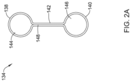
- FIG. 2 A is a side view of an illustrative tie.
- FIG. 2 B is a close up view of an end portion of an illustrative anti-migration stent.
- FIG. 2 C a close up view of an end portion of the illustrative anti-migration stent of FIG. 2 B including a fixation mechanism, such as a hemostasis clip device.
- FIG. 3 A is a close up view of an end portion of another illustrative anti-migration stent.
- FIG. 3 B a close up view of an end portion of the illustrative anti-migration stent of FIG. 3 A including a fixation mechanism.
- FIG. 4 A is a perspective view of another illustrative stent fixation mechanism.
- FIG. 4 B is a perspective view of the illustrative stent fixation mechanism of FIG. 4 A and an illustrative stent.
- FIG. 5 is a side view of another illustrative anti-migration stent.
- an endoluminal implant or stent, that can deliver luminal patency in patients with esophageal strictures.
- stents may be used in patients experiencing dysphagia, sometimes due to esophageal cancer.
- An esophageal stent may allow a patient to maintain nutrition via oral intake during cancer treatment or palliation periods.
- GI gastrointestinal
- stents described herein may be used and sized for use in other locations such as, but not limited to: bodily tissue, bodily organs, vascular lumens, non-vascular lumens and combinations thereof, such as, but not limited to, in the coronary or peripheral vasculature, trachea, bronchi, colon, small intestine, biliary tract, urinary tract, prostate, brain, stomach and the like.
- FIG. 1 illustrates a side view of an illustrative endoluminal implant 10 , such as, but not limited to, a stent.
- the stent 10 may be formed from an elongated tubular member 12 . While the stent 10 is described as generally tubular, it is contemplated that the stent 10 may take any cross-sectional shape desired.
- the stent 10 may have a first, or proximal, end 14 , a second, or distal, end 16 , and an intermediate region 18 disposed between the first end 14 and the second end 16 .
- the stent 10 may include a lumen 32 extending from a first opening adjacent the first end 14 to a second opening adjacent to the second end 16 to allow for the passage of food, fluids, etc.
- the stent 10 may be expandable from a first collapsed configuration (not explicitly shown) to a second expanded configuration.
- the stent 10 may be structured to extend across a stricture and to apply a radially outward pressure to the stricture in a lumen to open the lumen and allow for the passage of foods, fluids, air, etc.
- the stent 10 may have a woven structure, fabricated from a number of filaments or struts 36 .
- the stent 10 may be braided with one filament.
- the stent 10 may be braided with several filaments, as is found, for example, in the WallFlex®, WALLSTENT®, and Polyflex® stents, made and distributed by Boston Scientific, Corporation.
- the stent 10 may be knitted, such as the UltraflexTM stents made by Boston Scientific, Corporation.
- the stent 10 may be of a knotted type, such the Precision ColonicTM stents made by Boston Scientific, Corporation.
- the stent 10 may be a laser cut tubular member, such as the EPICTM stents made by Boston Scientific, Corporation.
- a laser cut tubular member may have an open and/or closed cell geometry including one or more interconnected filaments.
- an inner and/or outer surface of the stent 10 may be entirely, substantially or partially, covered with a polymeric covering or coating.
- a covering or coating which may help reduce food impaction and/or tumor or tissue ingrowth.
- the stent 10 may include a first end region 20 and a second end region 22 .
- the first end region 20 and the second end region 22 may include retention features or anti-migration flared regions 24 , 26 positioned adjacent to the first end 14 and the second end 16 of the stent 10 .
- the anti-migration flared regions 24 , 26 may be configured to engage an interior portion the walls of the esophagus.
- the retention features, or flared regions 24 , 26 may have a larger diameter than an intermediate region 18 of the stent 10 to prevent the stent 10 from migrating once placed in the esophagus. It is contemplated that the transition 28 , 30 from the cross-sectional area of the intermediate region 18 to the retention features or flared regions 24 , 26 may be gradual, sloped, or occur in an abrupt step-wise manner, as desired.
- the first anti-migration flared region 24 may have a first outer diameter and the second anti-migration flared region 26 may have a second outer diameter. In some instances, the first and second outer diameters may be approximately the same, while in other instances, the first and second outer diameters may be different. In some embodiments, the stent 10 may include only one or none of the anti-migration flared regions 24 , 26 .
- the first end region 20 may include an anti-migration flare 24 while the second end region 22 may have an outer diameter similar to the intermediate region 18 . It is further contemplated that the second end region 22 may include an anti-migration flare 26 while the first end region 20 may have an outer diameter similar to an outer diameter of the intermediate region 18 .
- the stent 10 may have a uniform outer diameter from the first end 14 to the second end 16 .
- the outer diameter of the intermediate region 18 may be in the range of 15 to 25 millimeters.
- the outer diameter of the anti-migration flares 24 , 26 may be in the range of 20 to 30 millimeters. It is contemplated that the outer diameter of the stent 10 may be varied to suit the desired application.
- the stent 10 can be made from a number of different materials such as, but not limited to, metals, metal alloys, shape memory alloys and/or polymers, as desired, enabling the stent 10 to be expanded into shape when accurately positioned within the body.
- the material may be selected to enable the stent 10 to be removed with relative ease as well.
- the stent 10 can be formed from alloys such as, but not limited to, nitinol and Elgiloy®. Depending the on material selected for construction, the stent 10 may be self-expanding or require an external force to expand the stent 10 .
- fibers may be used to make the stent 10 , which may be cored fibers, for example, having an outer shell made of nitinol having a platinum core. It is further contemplated the stent 10 may be formed from polymers including, but not limited to, polyethylene terephthalate (PET).
- PET polyethylene terephthalate
- the stent 10 may further include one or more ties (e.g., sutures or tethers 34 ) attached adjacent to the first end 14 of the stent 10 .
- the ties 34 may allow a physician to attach one or more fixation mechanisms or retention clips simultaneously to the ties 34 and the body lumen.
- the fixation mechanism may be a hemostasis clip, such as, but not limited to the Resolution® Clip made by Boston Scientific, Corporation, While the fixation mechanism is described as a clip, it is contemplated that any structure that allows for attachment of the tie 34 to the lumen wall may be used to secure the tie 34 within the lumen.
- the one or more ties 34 may be attached to the stent 10 at any point along the length thereof.
- the ties 34 may be affixed adjacent to the intermediate region 18 while in other instances, the ties 34 may be affixed adjacent to the second end 16 . This may allow the stent 10 to be anchored such that proximal, distal, or both proximal and distal movement is prevented.
- the ties 34 may be provided in a kit including the stent 10 and clips.
- the stent 10 may be delivered with the ties 34 previously attached thereto. This may allow a physician to attach the desired number of ties 34 to the stent 10 prior to use.
- a kit may also include a stent 10 with attached ties 34 and one or more clips. While the stent 10 is shown as having two ties 34 , it is contemplated that the stent 10 may include any number of ties 34 desired, such as, but not limited to, one, two, three, four, or more.
- the ties 34 may be made of a flexible, bendable material. In some instances, the ties 34 may be formed from suture material, or other biocompatible material. It is contemplated that the ties 34 may be formed from a biodegradable material that may “fall away” or be absorbed by the patient's body after a period of time, such as two to three weeks after the stent 10 is placed.
- the ties 34 may include a first end 38 , a second end 40 , and an intermediate region 42 disposed therebetween.
- the first end 38 may include a loop or other structure that allows a clamp, clip or other retention mechanism to grasp a portion of the tie.
- the first end 38 may be a solid or substantially solid enlarged portion that provides a surface area for the clip to grasp.
- the first end 38 may have a substantially “T” shape that provides a region for the clip to grasp.
- the second end 40 of the tie 34 may be affixed to a filament/strut 36 of the stent 10 . It is contemplated that the second end 40 may be affixed or attached to the stent 10 in a number of suitable ways.
- the tie 34 may be adhesively secured to the stent 10 or the tie 34 may be knotted, looped, or wound about a filament 36 .
- the intermediate region 42 of the tie 34 may be any length desired to provide a physician with easy access to attach a clip to the first end 38 of the tie 34 . While the ties 34 are illustrated as having a similar length, it is contemplated that the ties 34 may have differing lengths to allow for staggering of the clips, if desired.
- the second end 40 of the tie 34 may be secured to the stent 10 such that the tie 34 extends beyond or is capable of extending beyond the tubular portion 12 of the stent 10 .
- the tie 34 may be secured adjacent to the proximal end 14 of the stent 10 and extend proximally therefrom. While not explicitly shown, it is contemplated that the tie 34 may be secured adjacent to the distal end 15 of the stent 10 and extend distally therefrom.
- the tie 34 may be moved away from the tubular portion 12 of the stent 10 to allow the physician to easily secure a portion of the tissue and the tie 34 within the securing mechanism.
- the tie(s) 34 may be allowed to hang from the stent 10 .
- gravity may draw the ties(s) 34 into the lumen 32 of the stent 10 when they are not secured with a retention mechanism or clip.
- FIG. 5 which illustrates a side view of another illustrative endoluminal implant 400 , such as, but not limited to, a stent.
- the stent 400 may be similar in form and function to the stent 10 described above.
- the stent 400 may be formed from an elongated tubular member 412 . While the stent 400 is described as generally tubular, it is contemplated that the stent 400 may take any cross-sectional shape desired.
- the stent 400 may have a first end 414 , such as a proximal end, a second end 416 , such as a distal end, and an intermediate region 418 disposed between the first end 414 and the second end 416 .
- the stent 400 may include a lumen 432 extending from a first opening adjacent the first end 414 to a second opening adjacent to the second end 416 to allow for the passage of food, fluids, etc.
- the stent 400 may be expandable from a first collapsed configuration (not explicitly shown) to a second expanded configuration.
- the stent 400 may be structured to extend across a stricture and to apply a radially outward pressure to the stricture in a lumen to open the lumen and allow for the passage of foods, fluids, air, etc.
- the stent 400 may have a woven structure, fabricated from a number of filaments or struts 436 .
- the stent 400 may be a laser cut tubular member.
- an inner and/or outer surface of the stent 400 may be entirely, substantially or partially, covered with a polymeric covering or coating.
- a covering or coating which may help reduce food impaction and/or tumor or tissue ingrowth.
- the stent 400 may include a first end region 420 and a second end region 422 .
- the first end region 420 and the second end region 422 may include retention features or anti-migration flared regions 424 , 426 positioned adjacent to the first end 414 and the second end 416 of the stent 400 .
- the anti-migration flared regions 424 , 426 may be configured to engage an interior portion the walls of the body lumen, such as the esophagus.
- the retention features, or flared regions 424 , 426 may have a larger diameter than an intermediate region 418 of the stent 400 to prevent the stent 400 from migrating once placed in the body lumen, such as the esophagus. It is contemplated that the transition 428 , 430 from the cross-sectional area of the intermediate region 418 to the retention features or flared regions 424 , 426 may be gradual, sloped, or occur in an abrupt step-wise manner, as desired.
- the first anti-migration flared region 424 may have a first outer diameter and the second anti-migration flared region 426 may have a second outer diameter. In some instances, the first and second outer diameters may be approximately the same, while in other instances, the first and second outer diameters may be different. In some embodiments, the stent 400 may include only one or none of the anti-migration flared regions 424 , 426 . In some embodiments, the stent 400 may have a uniform outer diameter from the first end 414 to the second end 416 . In some embodiments, the outer diameter of the intermediate region 418 may be in the range of 15 to 25 millimeters. The outer diameter of the anti-migration flares 424 , 426 may be in the range of 20 to 30 millimeters. It is contemplated that the outer diameter of the stent 400 may be varied to suit the desired application.
- the stent 400 can be made from a number of different materials such as, but not limited to, metals, metal alloys, shape memory alloys and/or polymers, as desired, enabling the stent 400 to be expanded into shape when accurately positioned within the body.
- the material may be selected to enable the stent 400 to be removed with relative ease as well.
- the stent 400 can be formed from alloys such as, but not limited to, nitinol and Elgiloy®. Depending the on material selected for construction, the stent 400 may be self-expanding or require an external force to expand the stent 400 .
- fibers may be used to make the stent 400 , which may be cored fibers, for example, having an outer shell made of nitinol having a platinum core. It is further contemplated the stent 400 may be formed from polymers including, but not limited to, polyethylene terephthalate (PET).
- PET polyethylene terephthalate
- the stent 400 may further include one or more ties (e.g., sutures or tethers 434 ) attached to the tubular member 412 , such as adjacent to the first end 414 of the stent 400 .
- the ties 434 may allow a physician to attach one or more fixation mechanisms or clips simultaneously to the ties 434 and the body lumen.
- the fixation mechanism may be a hemostasis clip, such as, but not limited to the Resolution® Clip made by Boston Scientific, Corporation, While the fixation mechanism is described as a clip, it is contemplated that any structure that allows for attachment of the tie 434 to the lumen wall may be used to secure the tie 434 within the lumen.
- the one or more ties 434 may be attached to the stent 400 at any point along the length thereof.
- the ties 434 may be affixed adjacent to the intermediate region 418 while in other instances, the ties 434 may be affixed adjacent to either the first end 414 or the second end 416 , but not both. This may allow the stent 400 to be anchored such that proximal, distal, or both proximal and distal movement is prevented.
- the ties 434 may be provided in a kit including the stent 400 and clips.
- the stent 400 may be delivered with the ties 434 previously attached thereto. This may allow a physician to attach the desired number of ties 434 to the stent 400 prior to use.
- a kit may also include a stent 400 with attached ties 434 and one or more clips. While the stent 400 is shown as having four ties 434 , it is contemplated that the stent 400 may include any number of ties 434 desired, such as, but not limited to, one, two, three, four, or more.
- the ties 434 may be made of a flexible, bendable material. In some instances, the ties 434 may be formed from suture material, or other biocompatible material. It is contemplated that the ties 434 may be formed from a biodegradable material that may “fall away” or be absorbed by the patient's body after a period of time, such as two to three weeks after the stent 400 is placed.
- the ties 434 may include a first end 438 , a second end 440 , and an intermediate region 442 disposed therebetween.
- the first end 438 may include a loop or other structure that allows a clamp, clip or other retention mechanism to grasp a portion of the tie.
- the first end 438 may be a solid or substantially solid enlarged portion that provides a surface area for the clip to grasp.
- the first end 438 may have a substantially “T” shape that provides a region for the clip to grasp.
- the second end 440 of the tie 434 may be affixed to a filament/strut 436 of the stent 400 .
- the second end 40 may be affixed or attached to the stent 400 in a number of suitable ways.
- the tie 434 may be adhesively secured to the stent 400 or the tie 434 may be knotted, looped, or wound about a filament 436 .
- the intermediate region 442 of the tie 434 may be any length desired to provide a physician with easy access to attach a clip to the first end 438 of the tie 434 . While the ties 434 are illustrated as having a similar length, it is contemplated that the ties 434 may have differing lengths to allow for staggering of the clips, if desired.
- the second end 440 of the tie 434 may be secured to the stent 400 such that the tie 434 extends beyond or is capable of extending beyond the tubular portion 412 of the stent 400 .
- one or more ties 434 may be secured adjacent to the proximal end 414 of the stent 400 and extend proximally therefrom and one or more ties 434 may be secured adjacent to the distal end 416 of the stent and extend distally therefrom.
- the tie 434 may be moved away from the tubular portion 412 of the stent 400 to allow the physician to easily secure a portion of the tissue and the tie 434 within the securing mechanism.
- the tie(s) 434 may be allowed to hang from the stent 400 .
- gravity may draw the ties(s) 434 into the lumen 432 of the stent 400 when they are not secured with a retention mechanism or clip.
- the tie 134 may include a first looped end 138 having a first opening or aperture 144 and a second looped end 140 having a second opening or aperture 146 .
- the first looped end 138 and the second looped end 140 may be connected by an intermediate region 142 .
- the tie 134 may be formed as a unitary structure.
- the tie 134 may be formed as a single loop with portions of the loop 148 secured together along the intermediate region 142 to form the first opening 144 and the second opening 146 .
- the tie 134 may be formed of separate components secured to one another.
- first looped end 138 , second looped end 140 , and/or the intermediate region 142 may be formed as an individual component and secured to the remaining components, as desired.
- the tie 134 may be formed as a generally solid rectangular or oblong structure. One or more slits may be made in the rectangular structure adjacent to the first end and the second end thereof to form the first opening 144 and the second opening 146 . It is contemplated that the tie 134 may be formed in any manner that allows it to be secured to a stent, such as stent 10 , and to a clip. In some embodiments, the tie 134 may be provided with a clip, clamp, or other mechanism configured to grasp or surround a portion of the stent 10 .
- FIG. 2 B is a close up side view of an illustrative stent 10 with a tie 134 secured adjacent to the first end 14 of the stent 10 .
- the tie 134 may be looped around a filament 36 of the stent 10 to secure the tie 134 to the stent 10 .
- the tie 134 may be placed on a first side (for example, an inner or outer surface) of the filament 36 .
- the first looped end 138 may be wound or wrapped around the filament 36 on the second side.
- the first looped end 138 may be pushed through the second opening 146 and pulled to form a knot 160 and secure the tie 134 to the stent 10 in a looped manner, as illustrated in FIG. 2 B .
- an adhesive may be used in addition to, or in place of, the knot 160 .
- FIG. 2 C is a close up side view of an illustrative stent 10 with a tie 134 secured adjacent to the first end 14 of the stent 10 and an illustrative clip 150 affixed to the tie 134 .
- the stent 10 may be delivered and deployed to the target location using a stent delivery system and/or an endoscope, gastroscope or other guide means (not explicitly shown).
- the stent 10 may be advanced to the target location in a collapsed configuration and then expanded into an enlarged configuration. In some instances, it may be desirable to attach the stent 10 to the lumen to reduce or prevent migration of the stent 10 .
- the tie 134 may be moved away from the tubular portion 12 of the stent 10 to allow the physician to easily secure a portion of the tissue and the tie 134 within the securing mechanism.
- the tie 134 may extend proximally from the proximal end 14 of the stent 10 and be secured to the body lumen proximal of the proximal end 14 of the stent. In an esophageal application, this may reduce distal migration or movement of the stent 10 . This is just an example. In other applications, it may be desirable to secure a tie 134 distal of the distal end of the stent 10 to prevent proximal migration, for example.
- the physician may use a clip 150 to grip both a portion of the tie 134 (e.g., the first looped end 138 of the tie 134 ) and tissue of the lumen thus securing the stent 10 within the lumen. If a physician chooses not to use one or more of the ties 134 , the tie 134 may hang, or be otherwise disposed, within the lumen 32 of the stent 10 . The physician may choose to use as many clips 150 and/or ties 134 as they feel necessary to prevent migration of the stent 10 . In some instances, more than one clip 150 may be used with a single tie 134 .
- the clip 150 may include a pair of jaws 152 that may be opened and closed to grasp the tie 134 and tissue therebetween.
- the jaws 152 may be able to open and close a number of times prior to deploying the clip 150 to aid in positioning and/or repositioning of the clip 150 .
- the clip 150 may include a delivery system configured to advance the clip 150 , open and close the jaws 152 , and deploy the clip 150 within the lumen.
- the clip 150 may be left in place with the stent 10 or may be removed after a period of time. For example, the clip(s) 150 may be removed after tissue ingrowth has secured the stent 10 in place.
- FIG. 3 A is a close up side view of an illustrative stent 10 with another illustrative tie 234 secured adjacent to the first end 14 of the stent 10 .
- the tie 234 may be formed of a single loop of material, similar to a rubber band, defining an opening 244 .
- the tie 234 may be looped around a filament 36 of the stent 10 to secure the tie 234 to the stent 10 .
- the tie 234 may be placed on a first side (for example, an inner or outer surface) of the filament 36 .
- a first end 238 may be wound or wrapped around the filament 36 on the second side.
- the first end 238 may be pushed through the opening 246 adjacent to the second end 240 and pulled to form a knot 260 and secure the tie 234 to the stent 10 in a looped manner, as illustrated in FIG. 3 A .
- an adhesive may be used in addition to, or in place of, the knot 260 .
- FIG. 3 B is a close up side view of an illustrative stent 10 with a tie 234 secured adjacent to the first end 14 of the stent 10 and an illustrative clip 250 affixed to the tie 234 .
- the stent 10 may be delivered and deployed to the target location using a stent delivery system and/or an endoscope, gastroscope or other guide means (not explicitly shown).
- the stent 10 may be advanced to the target location in a collapsed configuration and then expanded into an enlarged configuration. In some instances, it may be desirable to attach the stent 10 to the lumen to reduce or prevent migration of the stent 10 .
- the physician may use a clip 150 to grip both the tie 134 and tissue of the lumen thus securing the stent 10 within the lumen. If a physician chooses not to use one or more of the ties 234 , the tie 234 may hang, or be otherwise disposed, within the lumen 32 of the stent 10 . The physician may choose to use as many clips 150 and/or ties 234 as they feel necessary to prevent migration of the stent 10 . In some instances, more than one clip 150 may be used with a single tie 234 .
- the clip 150 may include a pair of jaws 152 that may be opened and closed to grasp the tie 234 and tissue therebetween.
- the jaws 152 may be able to open and close a number of times prior to deploying the clip 150 to aid in positioning and/or repositioning of the clip 150 .
- the clip 150 may include a delivery system configured to advance the clip 150 , open and close the jaws 152 , and deploy the clip 150 within the lumen.
- FIGS. 4 A and 4 B illustrate another illustrative system 350 for reducing and/or preventing migration of an esophageal stent, such as stent 310 .
- the stent 310 may be similar in form and function to the stent 10 described above.
- the system 350 may be a mandible system configured to be placed in a patient's mouth.
- the system 350 may include a retainer 352 sized and shaped to be positioned over a patient's bottom teeth.
- the retainer 352 may be generally “U”-shaped having a first leg 354 and a second leg 356 .
- the first and second legs 354 , 356 may each include an aperture 358 , 360 extending therethrough.
- only one of the legs 354 , 356 may include an aperture 358 , 360 .
- the apertures may be positioned such along the retainer 352 such that they are near the back of a patient's mouth when the retainer is in a patient's mouth.
- One or more tethers or ties 362 may be attached to the apertures 358 , 360 .
- the ties 362 may be knotted, wound, wrapped, adhesively secured, or otherwise secured to the retainer 352 .
- the ties 362 may be made of a flexible, bendable material. In some instances, the ties 362 may be formed from suture material, or other biocompatible material.
- the ties 362 may be formed from a biodegradable material that may “fall away” or be absorbed by the patient's body after a period of time, such as two to three weeks after a stent is placed.
- Each of the ties 362 may include a clamp or clip 364 disposed adjacent a distal end 368 thereof.
- the clip 364 may include a pair of jaws 370 capable of opening and closing. In some instances the clip 364 may include a spring to bias the jaws 370 toward a closed position to grip tissue, etc. therebetween.
- the jaws 370 may clasp around a portion of a stent 310 , such as a filament 336 , to secure the tie 362 to the stent 310 .
- the tie 362 may be tied to, knotted around or adhesively secured to the stent 310 . It is contemplated that the retainer 352 may be removed from a patient's mouth after a period of time, such as but not limited, one week, or until the stent 310 is set in place on its own. The ties 362 may be disconnected (for example, untied, cut, etc.) and allowed to drop or hang from the stent 310 .
- the stents, delivery systems, and the various components thereof may be made from a metal, metal alloy, polymer (some examples of which are disclosed below), a metal-polymer composite, ceramics, combinations thereof, and the like, or other suitable material.
- suitable metals and metal alloys include stainless steel, such as 304V, 304L, and 316LV stainless steel; mild steel; nickel-titanium alloy such as linear-elastic and/or super-elastic nitinol; other nickel alloys such as nickel-chromium-molybdenum alloys (e.g., UNS: N06625 such as INCONEL® 625, UNS: N06022 such as HASTELLOY® C-22®, UNS: N10276 such as HASTELLOY® C276®, other HASTELLOY® alloys, and the like), nickel-copper alloys (e.g., UNS: N04400 such as MONEL® 400, NICKELVAC® 400, NICORRO
- linear elastic and/or non-super-elastic nitinol may be distinguished from super elastic nitinol in that the linear elastic and/or non-super-elastic nitinol does not display a substantial “superelastic plateau” or “flag region” in its stress/strain curve like super elastic nitinol does.
- linear elastic and/or non-super-elastic nitinol as recoverable strain increases, the stress continues to increase in a substantially linear, or a somewhat, but not necessarily entirely linear relationship until plastic deformation begins or at least in a relationship that is more linear that the super elastic plateau and/or flag region that may be seen with super elastic nitinol.
- linear elastic and/or non-super-elastic nitinol may also be termed “substantially” linear elastic and/or non-super-elastic nitinol.
- linear elastic and/or non-super-elastic nitinol may also be distinguishable from super elastic nitinol in that linear elastic and/or non-super-elastic nitinol may accept up to about 2-5% strain while remaining substantially elastic (e.g., before plastically deforming) whereas super elastic nitinol may accept up to about 8% strain before plastically deforming. Both of these materials can be distinguished from other linear elastic materials such as stainless steel (that can also can be distinguished based on its composition), which may accept only about 0.2 to 0.44 percent strain before plastically deforming.
- the linear elastic and/or non-super-elastic nickel-titanium alloy is an alloy that does not show any martensite/austenite phase changes that are detectable by differential scanning calorimetry (DSC) and dynamic metal thermal analysis (DMTA) analysis over a large temperature range.
- DSC differential scanning calorimetry
- DMTA dynamic metal thermal analysis
- the mechanical bending properties of such material may therefore be generally inert to the effect of temperature over this very broad range of temperature.
- the mechanical bending properties of the linear elastic and/or non-super-elastic nickel-titanium alloy at ambient or room temperature are substantially the same as the mechanical properties at body temperature, for example, in that they do not display a super-elastic plateau and/or flag region.
- the linear elastic and/or non-super-elastic nickel-titanium alloy maintains its linear elastic and/or non-super-elastic characteristics and/or properties.
- the linear elastic and/or non-super-elastic nickel-titanium alloy may be in the range of about 50 to about 60 weight percent nickel, with the remainder being essentially titanium. In some embodiments, the composition is in the range of about 54 to about 57 weight percent nickel. In some other embodiments, a superelastic alloy, for example a superelastic nitinol can be used to achieve desired properties.
- portions or all of the stents or delivery systems may also be doped with, made of, or otherwise include a radiopaque material.
- Radiopaque materials are generally understood to be materials which are opaque to RF energy in the wavelength range spanning x-ray to gamma-ray (at thicknesses of ⁇ 0.005′′). These materials are capable of producing a relatively dark image on a fluoroscopy screen relative to the light image that non-radiopaque materials such as tissue produce. This relatively bright image aids the user of the stents or delivery systems in determining its location.
- radiopaque materials can include, but are not limited to, gold, platinum, palladium, tantalum, tungsten alloy, polymer material loaded with a radiopaque filler, and the like. Additionally, other radiopaque marker bands and/or coils may also be incorporated into the design of the stents or delivery systems to achieve the same result.
- a degree of Magnetic Resonance Imaging (MM) compatibility is imparted into the stents or delivery systems.
- the stents or delivery systems or portions thereof may be made of a material that does not substantially distort the image and create substantial artifacts (i.e., gaps in the image). Certain ferromagnetic materials, for example, may not be suitable because they may create artifacts in an MRI image.
- the stents or delivery systems or portions thereof may also be made from a material that the MRI machine can image.
- Some materials that exhibit these characteristics include, for example, tungsten, cobalt-chromium-molybdenum alloys (e.g., UNS: R30003 such as ELGILOY®, PHYNOX®, and the like), nickel-cobalt-chromium-molybdenum alloys (e.g., UNS: R30035 such as MP35-N® and the like), nitinol, and the like, and others.
- cobalt-chromium-molybdenum alloys e.g., UNS: R30003 such as ELGILOY®, PHYNOX®, and the like
- nickel-cobalt-chromium-molybdenum alloys e.g., UNS: R30035 such as MP35-N® and the like
- nitinol and the like, and others.
- suitable polymers for the stents or delivery systems may include polytetrafluoroethylene (PTFE), ethylene tetrafluoroethylene (ETFE), fluorinated ethylene propylene (FEP), polyoxymethylene (POM, for example, DELRIN® available from DuPont), polyether block ester, polyurethane (for example, Polyurethane 85A), polypropylene (PP), polyvinylchloride (PVC), polyether-ester (for example, ARNITEL® available from DSM Engineering Plastics), ether or ester based copolymers (for example, butylene/poly(alkylene ether) phthalate and/or other polyester elastomers such as HYTREL® available from DuPont), polyamide (for example, DURETHAN® available from Bayer or CRISTAMID® available from Elf Atochem), elastomeric polyamides, block polyamide/ethers, polyether block amide (PEBA, for example available under the trade name PEBA
Abstract
An illustrative stent may comprise an elongated tubular member having a first end and a second end and an intermediate region disposed therebetween. The elongated tubular member may include at least one flexible tie affixed to an end thereof. The tie may allow the stent to be attached to a lumen wall with a clip, such as a retention clip, to inhibit migration of the stent within the body lumen.
Description
This application is a continuation of U.S. application Ser. No. 15/015,812, filed Feb. 4, 2016, which claims priority to U.S. Provisional Application No. 62/113,126, filed Feb. 6, 2015, the entire disclosures of which are herein incorporated by reference.
The present disclosure pertains to medical devices, and methods for manufacturing medical devices. More particularly, the present disclosure pertains to an anti-migration stent.
Implantable stents are devices that are placed in a body structure, such as a blood vessel or body cavity, to provide support and to maintain the structure open. These devices are manufactured by any one of a variety of different manufacturing methods and may be used according to any one of a variety of methods. Of the known medical devices, delivery systems, and methods, each has certain advantages and disadvantages. There is an ongoing need to provide alternative medical devices and delivery devices as well as alternative methods for manufacturing and using medical devices and delivery devices.
This disclosure provides design, material, manufacturing method, and use alternatives for medical devices. An example medical device may include a stent. The stent comprises:
an elongated tubular member having a first end, a second end and an intermediate region disposed therebetween, the elongated tubular member comprising at least one filament; and at least one flexible tie attached to the filament adjacent to the first end of the tubular member, the flexible tie having a first end and a second end.
Alternatively or additionally to any of the embodiments above, the first end of the flexible tie includes a first aperture and the second end of the flexible tie includes a second aperture.
Alternatively or additionally to any of the embodiments above, the stent further comprises an intermediate region disposed between the first aperture and the second aperture of the tie.
Alternatively or additionally to any of the embodiments above, the flexible tie comprises a single loop.
Alternatively or additionally to any of the embodiments above, the flexible tie is knotted to the filament of the tubular member.
Alternatively or additionally to any of the embodiments above, the flexible tie is adhesively secured to the filament of the tubular member.
Alternatively or additionally to any of the embodiments above, the at least one flexible tie comprises two or more flexible ties.
Alternatively or additionally to any of the embodiments above, the at least one flexible tie is biodegradable.
Alternatively or additionally to any of the embodiments above, the stent further comprises at least one clip configured to be secured to the at least one flexible tie.
Alternatively or additionally to any of the embodiments above, the clip comprises a pair of jaws configured to clamp around the at least one flexible tie.
An example kit for securing a stent comprises:
a stent having a first end, a second end and an intermediate region disposed therebetween;
at least one flexible tie; and
at least one clip.
Alternatively or additionally to any of the embodiments above, the flexible tie comprises a single loop.
Alternatively or additionally to any of the embodiments above, a first portion of the single loop is secured to a second portion of the single loop to define a first aperture and a second aperture.
Alternatively or additionally to any of the embodiments above, the clip comprises a pair of jaws.
Alternatively or additionally to any of the embodiments above, the clip comprises a hemostasis clip, such as, but not limited to the Resolution® Clip made by Boston Scientific, Corporation.
Alternatively or additionally to any of the embodiments above, wherein the flexible tie is secured to the stent adjacent to the first end of the stent.
Another example system for reducing migration of a stent comprises:
an elongated tubular member having a first end, a second end and an intermediate region disposed therebetween, the elongated tubular member comprising at least one woven filament;
a retainer; and
at least one tie extending between the elongated tubular member and the retainer.
Alternatively or additionally to any of the embodiments above, the retainer comprises at least one aperture for receiving the at least one tie.
Alternatively or additionally to any of the embodiments above, the at least one tie comprises a distal end including a clip, the clip configured to secure the tie to the tubular member.
Alternatively or additionally to any of the embodiments above, the clip comprise a pair of jaws configured to clasp the tubular member.
Alternatively or additionally to any of the embodiments above, the retainer comprises a “U”-shape.
The above summary of some embodiments is not intended to describe each disclosed embodiment or every implementation of the present disclosure. The Figures, and Detailed Description, which follow, more particularly exemplify these embodiments.
The invention may be more completely understood in consideration of the following detailed description of various embodiments in connection with the accompanying drawings, in which:
While the disclosure is amenable to various modifications and alternative forms, specifics thereof have been shown by way of example in the drawings and will be described in detail. It should be understood, however, that the intention is not to limit aspects of the invention to the particular embodiments described. On the contrary, the intention is to cover all modifications, equivalents, and alternatives falling within the scope of the invention.
For the following defined terms, these definitions shall be applied, unless a different definition is given in the claims or elsewhere in this specification.
All numeric values are herein assumed to be modified by the term “about”, whether or not explicitly indicated. The term “about” generally refers to a range of numbers that one of skill in the art would consider equivalent to the recited value (i.e., having the same function or result). In many instances, the term “about” may be indicative as including numbers that are rounded to the nearest significant figure.
The recitation of numerical ranges by endpoints includes all numbers within that range (e.g., 1 to 5 includes 1, 1.5, 2, 2.75, 3, 3.80, 4, and 5).
Although some suitable dimensions ranges and/or values pertaining to various components, features and/or specifications are disclosed, one of skill in the art, incited by the present disclosure, would understand desired dimensions, ranges and/or values may deviate from those expressly disclosed.
As used in this specification and the appended claims, the singular forms “a”, “an”, and “the” include plural referents unless the content clearly dictates otherwise. As used in this specification and the appended claims, the term “or” is generally employed in its sense including “and/or” unless the content clearly dictates otherwise.
The following detailed description should be read with reference to the drawings in which similar elements in different drawings are numbered the same. The detailed description and the drawings, which are not necessarily to scale, depict illustrative embodiments and are not intended to limit the scope of the invention. The illustrative embodiments depicted are intended only as exemplary. Selected features of any illustrative embodiment may be incorporated into an additional embodiment unless clearly stated to the contrary.
In some instances, it may be desirable to provide an endoluminal implant, or stent, that can deliver luminal patency in patients with esophageal strictures. Such stents may be used in patients experiencing dysphagia, sometimes due to esophageal cancer. An esophageal stent may allow a patient to maintain nutrition via oral intake during cancer treatment or palliation periods. However, a common complication of gastrointestinal (GI) stents is stent migration. It may be desirable to provide a stent that can deliver luminal patency while minimizing migration of the stent. While the embodiments disclosed herein are discussed with reference to esophageal stents, it is contemplated that the stents described herein may be used and sized for use in other locations such as, but not limited to: bodily tissue, bodily organs, vascular lumens, non-vascular lumens and combinations thereof, such as, but not limited to, in the coronary or peripheral vasculature, trachea, bronchi, colon, small intestine, biliary tract, urinary tract, prostate, brain, stomach and the like.
The stent 10 may be expandable from a first collapsed configuration (not explicitly shown) to a second expanded configuration. The stent 10 may be structured to extend across a stricture and to apply a radially outward pressure to the stricture in a lumen to open the lumen and allow for the passage of foods, fluids, air, etc.
The stent 10 may have a woven structure, fabricated from a number of filaments or struts 36. In some embodiments, the stent 10 may be braided with one filament. In other embodiments, the stent 10 may be braided with several filaments, as is found, for example, in the WallFlex®, WALLSTENT®, and Polyflex® stents, made and distributed by Boston Scientific, Corporation. In another embodiment, the stent 10 may be knitted, such as the Ultraflex™ stents made by Boston Scientific, Corporation. In yet another embodiment, the stent 10 may be of a knotted type, such the Precision Colonic™ stents made by Boston Scientific, Corporation. In still another embodiment, the stent 10 may be a laser cut tubular member, such as the EPIC™ stents made by Boston Scientific, Corporation. A laser cut tubular member may have an open and/or closed cell geometry including one or more interconnected filaments. In some instances, an inner and/or outer surface of the stent 10 may be entirely, substantially or partially, covered with a polymeric covering or coating. For example, a covering or coating which may help reduce food impaction and/or tumor or tissue ingrowth.
In some instances, in the expanded configuration, the stent 10 may include a first end region 20 and a second end region 22. In some embodiments, the first end region 20 and the second end region 22 may include retention features or anti-migration flared regions 24, 26 positioned adjacent to the first end 14 and the second end 16 of the stent 10. The anti-migration flared regions 24, 26 may be configured to engage an interior portion the walls of the esophagus. In some embodiments, the retention features, or flared regions 24, 26 may have a larger diameter than an intermediate region 18 of the stent 10 to prevent the stent 10 from migrating once placed in the esophagus. It is contemplated that the transition 28, 30 from the cross-sectional area of the intermediate region 18 to the retention features or flared regions 24, 26 may be gradual, sloped, or occur in an abrupt step-wise manner, as desired.
In some embodiments, the first anti-migration flared region 24 may have a first outer diameter and the second anti-migration flared region 26 may have a second outer diameter. In some instances, the first and second outer diameters may be approximately the same, while in other instances, the first and second outer diameters may be different. In some embodiments, the stent 10 may include only one or none of the anti-migration flared regions 24, 26. For example, the first end region 20 may include an anti-migration flare 24 while the second end region 22 may have an outer diameter similar to the intermediate region 18. It is further contemplated that the second end region 22 may include an anti-migration flare 26 while the first end region 20 may have an outer diameter similar to an outer diameter of the intermediate region 18. In some embodiments, the stent 10 may have a uniform outer diameter from the first end 14 to the second end 16. In some embodiments, the outer diameter of the intermediate region 18 may be in the range of 15 to 25 millimeters. The outer diameter of the anti-migration flares 24, 26 may be in the range of 20 to 30 millimeters. It is contemplated that the outer diameter of the stent 10 may be varied to suit the desired application.
It is contemplated that the stent 10 can be made from a number of different materials such as, but not limited to, metals, metal alloys, shape memory alloys and/or polymers, as desired, enabling the stent 10 to be expanded into shape when accurately positioned within the body. In some instances, the material may be selected to enable the stent 10 to be removed with relative ease as well. For example, the stent 10 can be formed from alloys such as, but not limited to, nitinol and Elgiloy®. Depending the on material selected for construction, the stent 10 may be self-expanding or require an external force to expand the stent 10. In some embodiments, fibers may be used to make the stent 10, which may be cored fibers, for example, having an outer shell made of nitinol having a platinum core. It is further contemplated the stent 10 may be formed from polymers including, but not limited to, polyethylene terephthalate (PET).
The stent 10 may further include one or more ties (e.g., sutures or tethers 34) attached adjacent to the first end 14 of the stent 10. As will be discussed in more detail below, the ties 34 may allow a physician to attach one or more fixation mechanisms or retention clips simultaneously to the ties 34 and the body lumen. In some instances, the fixation mechanism may be a hemostasis clip, such as, but not limited to the Resolution® Clip made by Boston Scientific, Corporation, While the fixation mechanism is described as a clip, it is contemplated that any structure that allows for attachment of the tie 34 to the lumen wall may be used to secure the tie 34 within the lumen. It is contemplated that the one or more ties 34 may be attached to the stent 10 at any point along the length thereof. For example, in some embodiments, the ties 34 may be affixed adjacent to the intermediate region 18 while in other instances, the ties 34 may be affixed adjacent to the second end 16. This may allow the stent 10 to be anchored such that proximal, distal, or both proximal and distal movement is prevented. In some embodiments, the ties 34 may be provided in a kit including the stent 10 and clips. In some instances, the stent 10 may be delivered with the ties 34 previously attached thereto. This may allow a physician to attach the desired number of ties 34 to the stent 10 prior to use. A kit may also include a stent 10 with attached ties 34 and one or more clips. While the stent 10 is shown as having two ties 34, it is contemplated that the stent 10 may include any number of ties 34 desired, such as, but not limited to, one, two, three, four, or more. The ties 34 may be made of a flexible, bendable material. In some instances, the ties 34 may be formed from suture material, or other biocompatible material. It is contemplated that the ties 34 may be formed from a biodegradable material that may “fall away” or be absorbed by the patient's body after a period of time, such as two to three weeks after the stent 10 is placed.
The ties 34 may include a first end 38, a second end 40, and an intermediate region 42 disposed therebetween. The first end 38 may include a loop or other structure that allows a clamp, clip or other retention mechanism to grasp a portion of the tie. In some embodiments, the first end 38 may be a solid or substantially solid enlarged portion that provides a surface area for the clip to grasp. In other embodiments, the first end 38 may have a substantially “T” shape that provides a region for the clip to grasp. The second end 40 of the tie 34 may be affixed to a filament/strut 36 of the stent 10. It is contemplated that the second end 40 may be affixed or attached to the stent 10 in a number of suitable ways. For example, the tie 34 may be adhesively secured to the stent 10 or the tie 34 may be knotted, looped, or wound about a filament 36. The intermediate region 42 of the tie 34 may be any length desired to provide a physician with easy access to attach a clip to the first end 38 of the tie 34. While the ties 34 are illustrated as having a similar length, it is contemplated that the ties 34 may have differing lengths to allow for staggering of the clips, if desired.
The second end 40 of the tie 34 may be secured to the stent 10 such that the tie 34 extends beyond or is capable of extending beyond the tubular portion 12 of the stent 10. For example, as shown in FIG. 1 , the tie 34 may be secured adjacent to the proximal end 14 of the stent 10 and extend proximally therefrom. While not explicitly shown, it is contemplated that the tie 34 may be secured adjacent to the distal end 15 of the stent 10 and extend distally therefrom. When a clip is used to secure the stent 10 within a lumen, the tie 34 may be moved away from the tubular portion 12 of the stent 10 to allow the physician to easily secure a portion of the tissue and the tie 34 within the securing mechanism. As will be described in more detail below, if a physician chooses not to use one or more of the ties 34, the tie(s) 34 may be allowed to hang from the stent 10. In some instances, gravity may draw the ties(s) 34 into the lumen 32 of the stent 10 when they are not secured with a retention mechanism or clip.
Referring additionally to FIG. 5 , which illustrates a side view of another illustrative endoluminal implant 400, such as, but not limited to, a stent. The stent 400 may be similar in form and function to the stent 10 described above. In some instances, the stent 400 may be formed from an elongated tubular member 412. While the stent 400 is described as generally tubular, it is contemplated that the stent 400 may take any cross-sectional shape desired. The stent 400 may have a first end 414, such as a proximal end, a second end 416, such as a distal end, and an intermediate region 418 disposed between the first end 414 and the second end 416. The stent 400 may include a lumen 432 extending from a first opening adjacent the first end 414 to a second opening adjacent to the second end 416 to allow for the passage of food, fluids, etc.
The stent 400 may be expandable from a first collapsed configuration (not explicitly shown) to a second expanded configuration. The stent 400 may be structured to extend across a stricture and to apply a radially outward pressure to the stricture in a lumen to open the lumen and allow for the passage of foods, fluids, air, etc.
In some embodiments, the stent 400 may have a woven structure, fabricated from a number of filaments or struts 436. In another embodiment, the stent 400 may be a laser cut tubular member. In some instances, an inner and/or outer surface of the stent 400 may be entirely, substantially or partially, covered with a polymeric covering or coating. For example, a covering or coating which may help reduce food impaction and/or tumor or tissue ingrowth.
In some instances, in the expanded configuration, the stent 400 may include a first end region 420 and a second end region 422. In some embodiments, the first end region 420 and the second end region 422 may include retention features or anti-migration flared regions 424, 426 positioned adjacent to the first end 414 and the second end 416 of the stent 400. The anti-migration flared regions 424, 426 may be configured to engage an interior portion the walls of the body lumen, such as the esophagus. In some embodiments, the retention features, or flared regions 424, 426 may have a larger diameter than an intermediate region 418 of the stent 400 to prevent the stent 400 from migrating once placed in the body lumen, such as the esophagus. It is contemplated that the transition 428, 430 from the cross-sectional area of the intermediate region 418 to the retention features or flared regions 424, 426 may be gradual, sloped, or occur in an abrupt step-wise manner, as desired.
In some embodiments, the first anti-migration flared region 424 may have a first outer diameter and the second anti-migration flared region 426 may have a second outer diameter. In some instances, the first and second outer diameters may be approximately the same, while in other instances, the first and second outer diameters may be different. In some embodiments, the stent 400 may include only one or none of the anti-migration flared regions 424, 426. In some embodiments, the stent 400 may have a uniform outer diameter from the first end 414 to the second end 416. In some embodiments, the outer diameter of the intermediate region 418 may be in the range of 15 to 25 millimeters. The outer diameter of the anti-migration flares 424, 426 may be in the range of 20 to 30 millimeters. It is contemplated that the outer diameter of the stent 400 may be varied to suit the desired application.
It is contemplated that the stent 400 can be made from a number of different materials such as, but not limited to, metals, metal alloys, shape memory alloys and/or polymers, as desired, enabling the stent 400 to be expanded into shape when accurately positioned within the body. In some instances, the material may be selected to enable the stent 400 to be removed with relative ease as well. For example, the stent 400 can be formed from alloys such as, but not limited to, nitinol and Elgiloy®. Depending the on material selected for construction, the stent 400 may be self-expanding or require an external force to expand the stent 400. In some embodiments, fibers may be used to make the stent 400, which may be cored fibers, for example, having an outer shell made of nitinol having a platinum core. It is further contemplated the stent 400 may be formed from polymers including, but not limited to, polyethylene terephthalate (PET).
The stent 400 may further include one or more ties (e.g., sutures or tethers 434) attached to the tubular member 412, such as adjacent to the first end 414 of the stent 400. As will be discussed in more detail below, the ties 434 may allow a physician to attach one or more fixation mechanisms or clips simultaneously to the ties 434 and the body lumen. In some instances, the fixation mechanism may be a hemostasis clip, such as, but not limited to the Resolution® Clip made by Boston Scientific, Corporation, While the fixation mechanism is described as a clip, it is contemplated that any structure that allows for attachment of the tie 434 to the lumen wall may be used to secure the tie 434 within the lumen. While the illustrative embodiment illustrates ties 434 attached to both the first and second ends 414, 416, it is contemplated that the one or more ties 434 may be attached to the stent 400 at any point along the length thereof. For example, in some embodiments, the ties 434 may be affixed adjacent to the intermediate region 418 while in other instances, the ties 434 may be affixed adjacent to either the first end 414 or the second end 416, but not both. This may allow the stent 400 to be anchored such that proximal, distal, or both proximal and distal movement is prevented. In some embodiments, the ties 434 may be provided in a kit including the stent 400 and clips. In some instances, the stent 400 may be delivered with the ties 434 previously attached thereto. This may allow a physician to attach the desired number of ties 434 to the stent 400 prior to use. A kit may also include a stent 400 with attached ties 434 and one or more clips. While the stent 400 is shown as having four ties 434, it is contemplated that the stent 400 may include any number of ties 434 desired, such as, but not limited to, one, two, three, four, or more. The ties 434 may be made of a flexible, bendable material. In some instances, the ties 434 may be formed from suture material, or other biocompatible material. It is contemplated that the ties 434 may be formed from a biodegradable material that may “fall away” or be absorbed by the patient's body after a period of time, such as two to three weeks after the stent 400 is placed.
The ties 434 may include a first end 438, a second end 440, and an intermediate region 442 disposed therebetween. The first end 438 may include a loop or other structure that allows a clamp, clip or other retention mechanism to grasp a portion of the tie. In some embodiments, the first end 438 may be a solid or substantially solid enlarged portion that provides a surface area for the clip to grasp. In other embodiments, the first end 438 may have a substantially “T” shape that provides a region for the clip to grasp. The second end 440 of the tie 434 may be affixed to a filament/strut 436 of the stent 400. It is contemplated that the second end 40 may be affixed or attached to the stent 400 in a number of suitable ways. For example, the tie 434 may be adhesively secured to the stent 400 or the tie 434 may be knotted, looped, or wound about a filament 436. The intermediate region 442 of the tie 434 may be any length desired to provide a physician with easy access to attach a clip to the first end 438 of the tie 434. While the ties 434 are illustrated as having a similar length, it is contemplated that the ties 434 may have differing lengths to allow for staggering of the clips, if desired.
The second end 440 of the tie 434 may be secured to the stent 400 such that the tie 434 extends beyond or is capable of extending beyond the tubular portion 412 of the stent 400. For example, as shown in FIG. 5 , one or more ties 434 may be secured adjacent to the proximal end 414 of the stent 400 and extend proximally therefrom and one or more ties 434 may be secured adjacent to the distal end 416 of the stent and extend distally therefrom. When a clip is used to secure the stent 400 within a lumen, the tie 434 may be moved away from the tubular portion 412 of the stent 400 to allow the physician to easily secure a portion of the tissue and the tie 434 within the securing mechanism. As will be described in more detail below, if a physician chooses not to use one or more of the ties 434, the tie(s) 434 may be allowed to hang from the stent 400. In some instances, gravity may draw the ties(s) 434 into the lumen 432 of the stent 400 when they are not secured with a retention mechanism or clip.
Referring now to FIG. 2A , which illustrates a close up view of an illustrative tie 134, the tie 134 may include a first looped end 138 having a first opening or aperture 144 and a second looped end 140 having a second opening or aperture 146. The first looped end 138 and the second looped end 140 may be connected by an intermediate region 142. In some instances, the tie 134 may be formed as a unitary structure. For example, the tie 134 may be formed as a single loop with portions of the loop 148 secured together along the intermediate region 142 to form the first opening 144 and the second opening 146. In other instances, the tie 134 may be formed of separate components secured to one another. For example, one or more of the first looped end 138, second looped end 140, and/or the intermediate region 142 may be formed as an individual component and secured to the remaining components, as desired. In yet another embodiment, the tie 134 may be formed as a generally solid rectangular or oblong structure. One or more slits may be made in the rectangular structure adjacent to the first end and the second end thereof to form the first opening 144 and the second opening 146. It is contemplated that the tie 134 may be formed in any manner that allows it to be secured to a stent, such as stent 10, and to a clip. In some embodiments, the tie 134 may be provided with a clip, clamp, or other mechanism configured to grasp or surround a portion of the stent 10.
The stents, delivery systems, and the various components thereof, may be made from a metal, metal alloy, polymer (some examples of which are disclosed below), a metal-polymer composite, ceramics, combinations thereof, and the like, or other suitable material. Some examples of suitable metals and metal alloys include stainless steel, such as 304V, 304L, and 316LV stainless steel; mild steel; nickel-titanium alloy such as linear-elastic and/or super-elastic nitinol; other nickel alloys such as nickel-chromium-molybdenum alloys (e.g., UNS: N06625 such as INCONEL® 625, UNS: N06022 such as HASTELLOY® C-22®, UNS: N10276 such as HASTELLOY® C276®, other HASTELLOY® alloys, and the like), nickel-copper alloys (e.g., UNS: N04400 such as MONEL® 400, NICKELVAC® 400, NICORROS® 400, and the like), nickel-cobalt-chromium-molybdenum alloys (e.g., UNS: R30035 such as MP35-N® and the like), nickel-molybdenum alloys (e.g., UNS: N10665 such as HASTELLOY® ALLOY B2®), other nickel-chromium alloys, other nickel-molybdenum alloys, other nickel-cobalt alloys, other nickel-iron alloys, other nickel-copper alloys, other nickel-tungsten or tungsten alloys, and the like; cobalt-chromium alloys; cobalt-chromium-molybdenum alloys (e.g., UNS: R30003 such as ELGILOY®, PHYNOX®, and the like); platinum enriched stainless steel; titanium; combinations thereof; and the like; or any other suitable material.
As alluded to herein, within the family of commercially available nickel-titanium or nitinol alloys, is a category designated “linear elastic” or “non-super-elastic” which, although may be similar in chemistry to conventional shape memory and super elastic varieties, may exhibit distinct and useful mechanical properties. Linear elastic and/or non-super-elastic nitinol may be distinguished from super elastic nitinol in that the linear elastic and/or non-super-elastic nitinol does not display a substantial “superelastic plateau” or “flag region” in its stress/strain curve like super elastic nitinol does. Instead, in the linear elastic and/or non-super-elastic nitinol, as recoverable strain increases, the stress continues to increase in a substantially linear, or a somewhat, but not necessarily entirely linear relationship until plastic deformation begins or at least in a relationship that is more linear that the super elastic plateau and/or flag region that may be seen with super elastic nitinol. Thus, for the purposes of this disclosure linear elastic and/or non-super-elastic nitinol may also be termed “substantially” linear elastic and/or non-super-elastic nitinol.
In some cases, linear elastic and/or non-super-elastic nitinol may also be distinguishable from super elastic nitinol in that linear elastic and/or non-super-elastic nitinol may accept up to about 2-5% strain while remaining substantially elastic (e.g., before plastically deforming) whereas super elastic nitinol may accept up to about 8% strain before plastically deforming. Both of these materials can be distinguished from other linear elastic materials such as stainless steel (that can also can be distinguished based on its composition), which may accept only about 0.2 to 0.44 percent strain before plastically deforming.
In some embodiments, the linear elastic and/or non-super-elastic nickel-titanium alloy is an alloy that does not show any martensite/austenite phase changes that are detectable by differential scanning calorimetry (DSC) and dynamic metal thermal analysis (DMTA) analysis over a large temperature range. For example, in some embodiments, there may be no martensite/austenite phase changes detectable by DSC and DMTA analysis in the range of about −60 degrees Celsius (° C.) to about 120° C. in the linear elastic and/or non-super-elastic nickel-titanium alloy. The mechanical bending properties of such material may therefore be generally inert to the effect of temperature over this very broad range of temperature. In some embodiments, the mechanical bending properties of the linear elastic and/or non-super-elastic nickel-titanium alloy at ambient or room temperature are substantially the same as the mechanical properties at body temperature, for example, in that they do not display a super-elastic plateau and/or flag region. In other words, across a broad temperature range, the linear elastic and/or non-super-elastic nickel-titanium alloy maintains its linear elastic and/or non-super-elastic characteristics and/or properties.
In some embodiments, the linear elastic and/or non-super-elastic nickel-titanium alloy may be in the range of about 50 to about 60 weight percent nickel, with the remainder being essentially titanium. In some embodiments, the composition is in the range of about 54 to about 57 weight percent nickel. In some other embodiments, a superelastic alloy, for example a superelastic nitinol can be used to achieve desired properties.
In at least some embodiments, portions or all of the stents or delivery systems may also be doped with, made of, or otherwise include a radiopaque material. Radiopaque materials are generally understood to be materials which are opaque to RF energy in the wavelength range spanning x-ray to gamma-ray (at thicknesses of <0.005″). These materials are capable of producing a relatively dark image on a fluoroscopy screen relative to the light image that non-radiopaque materials such as tissue produce. This relatively bright image aids the user of the stents or delivery systems in determining its location. Some examples of radiopaque materials can include, but are not limited to, gold, platinum, palladium, tantalum, tungsten alloy, polymer material loaded with a radiopaque filler, and the like. Additionally, other radiopaque marker bands and/or coils may also be incorporated into the design of the stents or delivery systems to achieve the same result.
In some embodiments, a degree of Magnetic Resonance Imaging (MM) compatibility is imparted into the stents or delivery systems. For example, the stents or delivery systems or portions thereof, may be made of a material that does not substantially distort the image and create substantial artifacts (i.e., gaps in the image). Certain ferromagnetic materials, for example, may not be suitable because they may create artifacts in an MRI image. The stents or delivery systems or portions thereof, may also be made from a material that the MRI machine can image. Some materials that exhibit these characteristics include, for example, tungsten, cobalt-chromium-molybdenum alloys (e.g., UNS: R30003 such as ELGILOY®, PHYNOX®, and the like), nickel-cobalt-chromium-molybdenum alloys (e.g., UNS: R30035 such as MP35-N® and the like), nitinol, and the like, and others.
Some examples of suitable polymers for the stents or delivery systems may include polytetrafluoroethylene (PTFE), ethylene tetrafluoroethylene (ETFE), fluorinated ethylene propylene (FEP), polyoxymethylene (POM, for example, DELRIN® available from DuPont), polyether block ester, polyurethane (for example, Polyurethane 85A), polypropylene (PP), polyvinylchloride (PVC), polyether-ester (for example, ARNITEL® available from DSM Engineering Plastics), ether or ester based copolymers (for example, butylene/poly(alkylene ether) phthalate and/or other polyester elastomers such as HYTREL® available from DuPont), polyamide (for example, DURETHAN® available from Bayer or CRISTAMID® available from Elf Atochem), elastomeric polyamides, block polyamide/ethers, polyether block amide (PEBA, for example available under the trade name PEBAX®), ethylene vinyl acetate copolymers (EVA), silicones, polyethylene (PE), Marlex high-density polyethylene, Marlex low-density polyethylene, linear low density polyethylene (for example REXELL®), polyester, polybutylene terephthalate (PBT), polyethylene terephthalate (PET), polytrimethylene terephthalate, polyethylene naphthalate (PEN), polyetheretherketone (PEEK), polyimide (PI), polyetherimide (PEI), polyphenylene sulfide (PPS), polyphenylene oxide (PPO), poly paraphenylene terephthalamide (for example, KEVLAR®), polysulfone, nylon, nylon-12 (such as GRILAMID® available from EMS American Grilon), perfluoro(propyl vinyl ether) (PFA), ethylene vinyl alcohol, polyolefin, polystyrene, epoxy, polyvinylidene chloride (PVdC), poly(styrene-b-isobutylene-b-styrene) (for example, SIBS and/or SIBS 50A), polycarbonates, ionomers, biocompatible polymers, other suitable materials, or mixtures, combinations, copolymers thereof, polymer/metal composites, and the like.
It should be understood that this disclosure is, in many respects, only illustrative. Changes may be made in details, particularly in matters of shape, size, and arrangement of steps without exceeding the scope of the disclosure. This may include, to the extent that it is appropriate, the use of any of the features of one example embodiment being used in other embodiments. The invention's scope is, of course, defined in the language in which the appended claims are expressed.
Claims (14)
1. A stent, the stent comprising:
an elongated tubular member having a first end, a second end and an intermediate region disposed therebetween, the elongated tubular member having at least one aperture at the first end; and
a biodegradable tie having a first discrete opening at a first end, a second discrete opening at a second end, the first and second discrete openings spaced apart by a middle region defining a first portion extending between the first discrete opening and the second discrete opening and a second portion extending between the first discrete opening and the second discrete opening, the first and second portions secured to one another along the middle region;
wherein the first end of the biodegradable tie is attached to the aperture in the elongated tubular member and the second end of the biodegradable tie is configured to extend beyond the first end of the elongated tubular member to be secured to tissue at a location beyond the first end of the elongated tubular member with a securing mechanism, wherein in the absence of the securing mechanism the second end of the biodegradable tie is configured to hang into a lumen of the elongated tubular member.
2. The stent of claim 1 , wherein the biodegradable tie is flexible.
3. The stent of claim 1 , wherein the elongated tubular member comprises at least one filament defining the at least one aperture, wherein the biodegradable tie is attached to the filament.
4. The stent of claim 3 , wherein the biodegradable tie is knotted to the filament of the elongated tubular member.
5. The stent of claim 3 , wherein the biodegradable tie is adhesively secured to the filament of the elongated tubular member.
6. The stent of claim 1 , further comprising a second biodegradable tie attached to the second end of the elongated tubular member.
7. The stent of claim 1 , further comprising at least one clip configured to be secured to the biodegradable tie.
8. The stent of claim 7 , wherein the clip is a hemostasis clip including a pair of jaws configured to clamp the biodegradable tie to tissue.
9. A kit for securing a stent, the kit comprising:
a stent having a first end, a second end and an intermediate region disposed therebetween;
at least one biodegradable tie having a first end configured to be attached to the first end of the stent and configured to extend beyond the first end of the stent; and
at least one clip configured to be removably attached to the at least one biodegradable tie, wherein the at least one clip is a hemostasis clip including a pair of jaws configured to clamp the at least one biodegradable tie to tissue;
wherein when the at least one biodegradable tie is attached to the stent, and in the absence of the clip, a second end of the at least one biodegradable tie is configured to hang freely into a lumen of the stent via gravity.
10. The kit of claim 9 , wherein the at least one biodegradable tie comprises a single loop.
11. The kit of claim 10 , wherein a first portion of the single loop is secured to a second portion along an intermediate of the single loop to define a first aperture and a second aperture.
12. The kit of claim 9 , wherein the stent includes a filament and the at least one biodegradable tie is wrapped around the filament adjacent to the first end of the stent.
13. The kit of claim 9 , wherein the at least one biodegradable tie includes a plurality of ties, some of which are attached to the first end of the stent and some of which are attached to the second end of the stent, wherein the at least one clip includes a plurality of clips, one for each tie.
14. The kit of claim 9 , wherein the at least one biodegradable tie is flexible.
Priority Applications (2)
| Application Number | Priority Date | Filing Date | Title |
|---|---|---|---|
| US17/411,211 US11806258B2 (en) | 2015-02-06 | 2021-08-25 | Anti-migration stent |
| US18/370,681 US20240009010A1 (en) | 2015-02-06 | 2023-09-20 | Anti-migration stent |
Applications Claiming Priority (3)
| Application Number | Priority Date | Filing Date | Title |
|---|---|---|---|
| US201562113126P | 2015-02-06 | 2015-02-06 | |
| US15/015,812 US11123204B2 (en) | 2015-02-06 | 2016-02-04 | Anti-migration stent |
| US17/411,211 US11806258B2 (en) | 2015-02-06 | 2021-08-25 | Anti-migration stent |
Related Parent Applications (1)
| Application Number | Title | Priority Date | Filing Date |
|---|---|---|---|
| US15/015,812 Continuation US11123204B2 (en) | 2015-02-06 | 2016-02-04 | Anti-migration stent |
Related Child Applications (1)
| Application Number | Title | Priority Date | Filing Date |
|---|---|---|---|
| US18/370,681 Continuation US20240009010A1 (en) | 2015-02-06 | 2023-09-20 | Anti-migration stent |
Publications (2)
| Publication Number | Publication Date |
|---|---|
| US20210378846A1 US20210378846A1 (en) | 2021-12-09 |
| US11806258B2 true US11806258B2 (en) | 2023-11-07 |
Family
ID=55588529
Family Applications (3)
| Application Number | Title | Priority Date | Filing Date |
|---|---|---|---|
| US15/015,812 Active 2038-09-30 US11123204B2 (en) | 2015-02-06 | 2016-02-04 | Anti-migration stent |
| US17/411,211 Active 2036-04-02 US11806258B2 (en) | 2015-02-06 | 2021-08-25 | Anti-migration stent |
| US18/370,681 Pending US20240009010A1 (en) | 2015-02-06 | 2023-09-20 | Anti-migration stent |
Family Applications Before (1)
| Application Number | Title | Priority Date | Filing Date |
|---|---|---|---|
| US15/015,812 Active 2038-09-30 US11123204B2 (en) | 2015-02-06 | 2016-02-04 | Anti-migration stent |
Family Applications After (1)
| Application Number | Title | Priority Date | Filing Date |
|---|---|---|---|
| US18/370,681 Pending US20240009010A1 (en) | 2015-02-06 | 2023-09-20 | Anti-migration stent |
Country Status (2)
| Country | Link |
|---|---|
| US (3) | US11123204B2 (en) |
| WO (1) | WO2016126967A1 (en) |
Families Citing this family (6)
| Publication number | Priority date | Publication date | Assignee | Title |
|---|---|---|---|---|
| NZ554495A (en) | 2004-10-15 | 2010-09-30 | Bfkw Llc | Bariatric device and method with lumen exerting force on eosophagus or stomach areas |
| US8529431B2 (en) | 2007-02-14 | 2013-09-10 | Bfkw, Llc | Bariatric device and method |
| JP5526038B2 (en) * | 2008-01-17 | 2014-06-18 | ボストン サイエンティフィック サイムド,インコーポレイテッド | Stent with anti-migration feature |
| JP6730991B2 (en) | 2014-12-29 | 2020-07-29 | ビーエフケイダブリュ・エルエルシーBfkw, Llc | Intraluminal device |
| WO2018073752A1 (en) * | 2016-10-17 | 2018-04-26 | Bfkw, Llc | Intraluminal device and fixation technique |
| JP7039957B2 (en) * | 2017-11-24 | 2022-03-23 | 株式会社ジェイ・エム・エス | Stent |
Citations (31)
| Publication number | Priority date | Publication date | Assignee | Title |
|---|---|---|---|---|
| US20030176912A1 (en) | 2002-02-26 | 2003-09-18 | Chuter Timothy A.M. | Endovascular graft device and methods for attaching components thereof |
| US6663663B2 (en) | 2001-05-14 | 2003-12-16 | M.I. Tech Co., Ltd. | Stent |
| US20050131515A1 (en) | 2003-12-16 | 2005-06-16 | Cully Edward H. | Removable stent-graft |
| US20060253191A1 (en) | 2003-12-23 | 2006-11-09 | Amr Salahieh | Methods and apparatus for endovascular heart valve replacement comprising tissue grasping elements |
| US7195016B2 (en) | 2004-01-07 | 2007-03-27 | E. Benson Hood Laboratories | Transtracheal oxygen stent |
| US20070198074A1 (en) | 2002-11-01 | 2007-08-23 | Mitchell Dann | Devices and methods for endolumenal gastrointestinal bypass |
| US7494461B2 (en) | 2003-09-30 | 2009-02-24 | Boston Scientific Scimed, Inc. | Through the scope tension member release clip |
| US7547321B2 (en) | 2001-07-26 | 2009-06-16 | Alveolus Inc. | Removable stent and method of using the same |
| US7556647B2 (en) | 2003-10-08 | 2009-07-07 | Arbor Surgical Technologies, Inc. | Attachment device and methods of using the same |
| US20090312603A1 (en) | 2008-06-17 | 2009-12-17 | Usgi Medical, Inc. | Endoscopic tissue anchor deployment |
| US7879052B2 (en) | 2001-10-05 | 2011-02-01 | Boston Scientific Scimed, Inc. | Device and method for through the scope endoscopic hemostatic clipping |
| WO2011115793A1 (en) | 2010-03-17 | 2011-09-22 | National Jewish Health | Airway anchor suture to prevent airway stent migration |
| US20120022633A1 (en) | 2010-07-23 | 2012-01-26 | Christopher Olson | Retaining mechanisms for prosthetic valves |
| US20120053681A1 (en) | 2010-08-24 | 2012-03-01 | St. Jude Medical, Inc. | Repositioning of prosthetic heart valve and deployment |
| US8133240B2 (en) | 2001-10-24 | 2012-03-13 | Boston Scientific Scimed, Inc. | Multiple hemoclip system for an endoscope |
| US20120071987A1 (en) | 2010-03-25 | 2012-03-22 | Mayo Foundation For Medical Education And Research | Removable and/or retrievable stents and kits |
| US8187217B2 (en) | 1998-09-10 | 2012-05-29 | Renati Richard J | TMR shunt |
| US20120310327A1 (en) | 2011-05-31 | 2012-12-06 | Cook Medical Technologies Llc | Non-foreshortening, axial tension constrainable stent |
| US20130090714A1 (en) | 2011-10-11 | 2013-04-11 | Cook Medical Technologies Llc | Stent delivery, repositioning, and removal system |
| US8647381B2 (en) | 2007-10-25 | 2014-02-11 | Symetis Sa | Stents, valved-stents, and methods and systems for delivery thereof |
| US8702785B2 (en) | 2005-12-30 | 2014-04-22 | Cordis Corporation | Migration resistant prosthetic stent graft for treatment of abdominal aortic aneurysm |
| US8715334B2 (en) | 2011-07-14 | 2014-05-06 | Boston Scientific Scimed, Inc. | Anti-migration stent with quill filaments |
| WO2014081796A1 (en) | 2012-11-21 | 2014-05-30 | Edwards Lifesciences Corporation | Retaining mechanisms for prosthetic heart valves |
| EP2777654A2 (en) | 2013-03-15 | 2014-09-17 | Cook Medical Technologies LLC | Wireless medical device release mechanism |
| US20140277573A1 (en) | 2013-03-15 | 2014-09-18 | Merit Medical Systems, Inc. | Esophageal stent |
| WO2014141239A1 (en) | 2013-03-14 | 2014-09-18 | 4Tech Inc. | Stent with tether interface |
| US20140277560A1 (en) | 2013-03-14 | 2014-09-18 | Boston Scientific Scimed, Inc. | Stent having removable anchoring element |
| US20140277394A1 (en) | 2013-03-15 | 2014-09-18 | Cook Medical Technologies Llc | Stents having barbs protected during delivery |
| US8845658B2 (en) | 2007-02-26 | 2014-09-30 | Boston Scientific Scimed, Inc. | Hemostatic clip and delivery system |
| US8974371B2 (en) | 2003-09-30 | 2015-03-10 | Boston Scientific Scimed, Inc. | Through the scope tension member release clip |
| US20160074183A1 (en) | 2007-12-26 | 2016-03-17 | Cook Medical Technologies Llc | Low profile non-symmetrical stent |
Family Cites Families (3)
| Publication number | Priority date | Publication date | Assignee | Title |
|---|---|---|---|---|
| US8274124B2 (en) * | 2010-07-07 | 2012-09-25 | United Microelectronics Corp. | Backside illuminated image sensor |
| US8975623B2 (en) * | 2011-05-20 | 2015-03-10 | Panasonic Intellectual Property Management Co., Ltd. | Organic electroluminescence element |
| US9318710B2 (en) * | 2012-07-30 | 2016-04-19 | Universal Display Corporation | Organic electroluminescent materials and devices |
-
2016
- 2016-02-04 WO PCT/US2016/016606 patent/WO2016126967A1/en active Application Filing
- 2016-02-04 US US15/015,812 patent/US11123204B2/en active Active
-
2021
- 2021-08-25 US US17/411,211 patent/US11806258B2/en active Active
-
2023
- 2023-09-20 US US18/370,681 patent/US20240009010A1/en active Pending
Patent Citations (35)
| Publication number | Priority date | Publication date | Assignee | Title |
|---|---|---|---|---|
| US8187217B2 (en) | 1998-09-10 | 2012-05-29 | Renati Richard J | TMR shunt |
| US6663663B2 (en) | 2001-05-14 | 2003-12-16 | M.I. Tech Co., Ltd. | Stent |
| US7547321B2 (en) | 2001-07-26 | 2009-06-16 | Alveolus Inc. | Removable stent and method of using the same |
| US7879052B2 (en) | 2001-10-05 | 2011-02-01 | Boston Scientific Scimed, Inc. | Device and method for through the scope endoscopic hemostatic clipping |
| US8709027B2 (en) | 2001-10-05 | 2014-04-29 | Boston Scientific Scimed, Inc. | Device and method for through the scope endoscopic hemostatic clipping |
| US8133240B2 (en) | 2001-10-24 | 2012-03-13 | Boston Scientific Scimed, Inc. | Multiple hemoclip system for an endoscope |
| US20030176912A1 (en) | 2002-02-26 | 2003-09-18 | Chuter Timothy A.M. | Endovascular graft device and methods for attaching components thereof |
| US20070198074A1 (en) | 2002-11-01 | 2007-08-23 | Mitchell Dann | Devices and methods for endolumenal gastrointestinal bypass |
| US8974371B2 (en) | 2003-09-30 | 2015-03-10 | Boston Scientific Scimed, Inc. | Through the scope tension member release clip |
| US7494461B2 (en) | 2003-09-30 | 2009-02-24 | Boston Scientific Scimed, Inc. | Through the scope tension member release clip |
| US7556647B2 (en) | 2003-10-08 | 2009-07-07 | Arbor Surgical Technologies, Inc. | Attachment device and methods of using the same |
| US20050131515A1 (en) | 2003-12-16 | 2005-06-16 | Cully Edward H. | Removable stent-graft |
| US20060253191A1 (en) | 2003-12-23 | 2006-11-09 | Amr Salahieh | Methods and apparatus for endovascular heart valve replacement comprising tissue grasping elements |
| US7195016B2 (en) | 2004-01-07 | 2007-03-27 | E. Benson Hood Laboratories | Transtracheal oxygen stent |
| US8702785B2 (en) | 2005-12-30 | 2014-04-22 | Cordis Corporation | Migration resistant prosthetic stent graft for treatment of abdominal aortic aneurysm |
| US8845658B2 (en) | 2007-02-26 | 2014-09-30 | Boston Scientific Scimed, Inc. | Hemostatic clip and delivery system |
| US8647381B2 (en) | 2007-10-25 | 2014-02-11 | Symetis Sa | Stents, valved-stents, and methods and systems for delivery thereof |
| US20160074183A1 (en) | 2007-12-26 | 2016-03-17 | Cook Medical Technologies Llc | Low profile non-symmetrical stent |
| US20090312603A1 (en) | 2008-06-17 | 2009-12-17 | Usgi Medical, Inc. | Endoscopic tissue anchor deployment |
| US8512414B2 (en) | 2010-03-17 | 2013-08-20 | National Jewish Health | Airway anchor suture to prevent airway stent migration |
| WO2011115793A1 (en) | 2010-03-17 | 2011-09-22 | National Jewish Health | Airway anchor suture to prevent airway stent migration |
| US20120071987A1 (en) | 2010-03-25 | 2012-03-22 | Mayo Foundation For Medical Education And Research | Removable and/or retrievable stents and kits |
| US20120022633A1 (en) | 2010-07-23 | 2012-01-26 | Christopher Olson | Retaining mechanisms for prosthetic valves |
| US20120053681A1 (en) | 2010-08-24 | 2012-03-01 | St. Jude Medical, Inc. | Repositioning of prosthetic heart valve and deployment |
| US20120310327A1 (en) | 2011-05-31 | 2012-12-06 | Cook Medical Technologies Llc | Non-foreshortening, axial tension constrainable stent |
| US8715334B2 (en) | 2011-07-14 | 2014-05-06 | Boston Scientific Scimed, Inc. | Anti-migration stent with quill filaments |
| US20130090714A1 (en) | 2011-10-11 | 2013-04-11 | Cook Medical Technologies Llc | Stent delivery, repositioning, and removal system |
| WO2014081796A1 (en) | 2012-11-21 | 2014-05-30 | Edwards Lifesciences Corporation | Retaining mechanisms for prosthetic heart valves |
| WO2014141239A1 (en) | 2013-03-14 | 2014-09-18 | 4Tech Inc. | Stent with tether interface |
| US20140277560A1 (en) | 2013-03-14 | 2014-09-18 | Boston Scientific Scimed, Inc. | Stent having removable anchoring element |
| US20160022448A1 (en) | 2013-03-14 | 2016-01-28 | 4Tech Inc. | Stent with tether interface |
| US20140277573A1 (en) | 2013-03-15 | 2014-09-18 | Merit Medical Systems, Inc. | Esophageal stent |
| US20140277341A1 (en) | 2013-03-15 | 2014-09-18 | Cook Medical Technologies Llc | Wireless medical device release mechanism |
| US20140277394A1 (en) | 2013-03-15 | 2014-09-18 | Cook Medical Technologies Llc | Stents having barbs protected during delivery |
| EP2777654A2 (en) | 2013-03-15 | 2014-09-17 | Cook Medical Technologies LLC | Wireless medical device release mechanism |
Non-Patent Citations (1)
| Title |
|---|
| International Search Report and Written Opinion, dated May 20, 2016 for International Application No. PCT/US2016/016606. |
Also Published As
| Publication number | Publication date |
|---|---|
| US20240009010A1 (en) | 2024-01-11 |
| US20210378846A1 (en) | 2021-12-09 |
| WO2016126967A1 (en) | 2016-08-11 |
| US11123204B2 (en) | 2021-09-21 |
| US20160228268A1 (en) | 2016-08-11 |
Similar Documents
| Publication | Publication Date | Title |
|---|---|---|
| US11806258B2 (en) | Anti-migration stent | |
| US10166126B2 (en) | Inflatable balloon stent | |
| US11147695B2 (en) | Implantable medical device with reduced migration capabilities | |
| US10888410B2 (en) | Stent and sleeve deployment | |
| US11883310B2 (en) | Repositionable and removable stents | |
| US20230255808A1 (en) | Removable stent | |
| US20180311057A1 (en) | Inflatable stent | |
| US11666429B2 (en) | Stents, systems, and methods for gastrointestinal tract treatment | |
| US20240122731A1 (en) | Repositionable and removable stents | |
| US11690743B2 (en) | Stent delivery system | |
| US20240016638A1 (en) | Anastomosis Anchors for Dynamic Gastric Bypass Device |
Legal Events
| Date | Code | Title | Description |
|---|---|---|---|
| FEPP | Fee payment procedure |
Free format text: ENTITY STATUS SET TO UNDISCOUNTED (ORIGINAL EVENT CODE: BIG.); ENTITY STATUS OF PATENT OWNER: LARGE ENTITY |
|
| STPP | Information on status: patent application and granting procedure in general |
Free format text: DOCKETED NEW CASE - READY FOR EXAMINATION |
|
| STPP | Information on status: patent application and granting procedure in general |
Free format text: NON FINAL ACTION MAILED |
|
| STPP | Information on status: patent application and granting procedure in general |
Free format text: NOTICE OF ALLOWANCE MAILED -- APPLICATION RECEIVED IN OFFICE OF PUBLICATIONS |
|
| STPP | Information on status: patent application and granting procedure in general |
Free format text: PUBLICATIONS -- ISSUE FEE PAYMENT VERIFIED |
|
| STCF | Information on status: patent grant |
Free format text: PATENTED CASE |