US11805604B2 - Display device - Google Patents
Display device Download PDFInfo
- Publication number
- US11805604B2 US11805604B2 US17/353,553 US202117353553A US11805604B2 US 11805604 B2 US11805604 B2 US 11805604B2 US 202117353553 A US202117353553 A US 202117353553A US 11805604 B2 US11805604 B2 US 11805604B2
- Authority
- US
- United States
- Prior art keywords
- support
- display device
- display panel
- housing
- disposed
- Prior art date
- Legal status (The legal status is an assumption and is not a legal conclusion. Google has not performed a legal analysis and makes no representation as to the accuracy of the status listed.)
- Active, expires
Links
- 230000008878 coupling Effects 0.000 claims description 16
- 238000010168 coupling process Methods 0.000 claims description 16
- 238000005859 coupling reaction Methods 0.000 claims description 16
- 230000007423 decrease Effects 0.000 claims description 2
- 238000003825 pressing Methods 0.000 claims description 2
- 102100024853 Carnitine O-palmitoyltransferase 2, mitochondrial Human genes 0.000 description 31
- 101000909313 Homo sapiens Carnitine O-palmitoyltransferase 2, mitochondrial Proteins 0.000 description 31
- 101000859570 Homo sapiens Carnitine O-palmitoyltransferase 1, liver isoform Proteins 0.000 description 19
- 101000989606 Homo sapiens Cholinephosphotransferase 1 Proteins 0.000 description 19
- 101100347958 Arabidopsis thaliana NAP1;1 gene Proteins 0.000 description 12
- 101150046077 nfa1 gene Proteins 0.000 description 12
- 239000013256 coordination polymer Substances 0.000 description 11
- 101100347962 Arabidopsis thaliana NAP1;2 gene Proteins 0.000 description 10
- 101100180304 Arabidopsis thaliana ISS1 gene Proteins 0.000 description 6
- 101100519257 Saccharomyces cerevisiae (strain ATCC 204508 / S288c) PDR17 gene Proteins 0.000 description 6
- 101100042407 Saccharomyces cerevisiae (strain ATCC 204508 / S288c) SFB2 gene Proteins 0.000 description 6
- 238000000034 method Methods 0.000 description 4
- 239000000853 adhesive Substances 0.000 description 3
- 230000001070 adhesive effect Effects 0.000 description 3
- 238000004519 manufacturing process Methods 0.000 description 3
- 230000008859 change Effects 0.000 description 2
- 239000004973 liquid crystal related substance Substances 0.000 description 2
- 239000000463 material Substances 0.000 description 2
- 238000012986 modification Methods 0.000 description 2
- 230000004048 modification Effects 0.000 description 2
- 230000008569 process Effects 0.000 description 2
- 239000004820 Pressure-sensitive adhesive Substances 0.000 description 1
- 238000005452 bending Methods 0.000 description 1
- 230000008901 benefit Effects 0.000 description 1
- 238000010586 diagram Methods 0.000 description 1
- 239000013013 elastic material Substances 0.000 description 1
- 239000012530 fluid Substances 0.000 description 1
- 238000007689 inspection Methods 0.000 description 1
- 239000002184 metal Substances 0.000 description 1
- 230000000149 penetrating effect Effects 0.000 description 1
- 239000002096 quantum dot Substances 0.000 description 1
- 230000003252 repetitive effect Effects 0.000 description 1
- 239000011347 resin Substances 0.000 description 1
- 229920005989 resin Polymers 0.000 description 1
- 230000000717 retained effect Effects 0.000 description 1
- 238000005406 washing Methods 0.000 description 1
- 210000000707 wrist Anatomy 0.000 description 1
Images


Classifications
-
- H—ELECTRICITY
- H04—ELECTRIC COMMUNICATION TECHNIQUE
- H04M—TELEPHONIC COMMUNICATION
- H04M1/00—Substation equipment, e.g. for use by subscribers
- H04M1/02—Constructional features of telephone sets
- H04M1/0202—Portable telephone sets, e.g. cordless phones, mobile phones or bar type handsets
- H04M1/026—Details of the structure or mounting of specific components
- H04M1/0266—Details of the structure or mounting of specific components for a display module assembly
- H04M1/0268—Details of the structure or mounting of specific components for a display module assembly including a flexible display panel
-
- G—PHYSICS
- G09—EDUCATION; CRYPTOGRAPHY; DISPLAY; ADVERTISING; SEALS
- G09F—DISPLAYING; ADVERTISING; SIGNS; LABELS OR NAME-PLATES; SEALS
- G09F9/00—Indicating arrangements for variable information in which the information is built-up on a support by selection or combination of individual elements
- G09F9/30—Indicating arrangements for variable information in which the information is built-up on a support by selection or combination of individual elements in which the desired character or characters are formed by combining individual elements
- G09F9/301—Indicating arrangements for variable information in which the information is built-up on a support by selection or combination of individual elements in which the desired character or characters are formed by combining individual elements flexible foldable or roll-able electronic displays, e.g. thin LCD, OLED
-
- H—ELECTRICITY
- H05—ELECTRIC TECHNIQUES NOT OTHERWISE PROVIDED FOR
- H05K—PRINTED CIRCUITS; CASINGS OR CONSTRUCTIONAL DETAILS OF ELECTRIC APPARATUS; MANUFACTURE OF ASSEMBLAGES OF ELECTRICAL COMPONENTS
- H05K5/00—Casings, cabinets or drawers for electric apparatus
- H05K5/02—Details
- H05K5/0217—Mechanical details of casings
-
- G—PHYSICS
- G06—COMPUTING; CALCULATING OR COUNTING
- G06F—ELECTRIC DIGITAL DATA PROCESSING
- G06F1/00—Details not covered by groups G06F3/00 - G06F13/00 and G06F21/00
- G06F1/16—Constructional details or arrangements
- G06F1/1613—Constructional details or arrangements for portable computers
- G06F1/1615—Constructional details or arrangements for portable computers with several enclosures having relative motions, each enclosure supporting at least one I/O or computing function
- G06F1/1616—Constructional details or arrangements for portable computers with several enclosures having relative motions, each enclosure supporting at least one I/O or computing function with folding flat displays, e.g. laptop computers or notebooks having a clamshell configuration, with body parts pivoting to an open position around an axis parallel to the plane they define in closed position
-
- G—PHYSICS
- G06—COMPUTING; CALCULATING OR COUNTING
- G06F—ELECTRIC DIGITAL DATA PROCESSING
- G06F1/00—Details not covered by groups G06F3/00 - G06F13/00 and G06F21/00
- G06F1/16—Constructional details or arrangements
- G06F1/1613—Constructional details or arrangements for portable computers
- G06F1/1633—Constructional details or arrangements of portable computers not specific to the type of enclosures covered by groups G06F1/1615 - G06F1/1626
- G06F1/1637—Details related to the display arrangement, including those related to the mounting of the display in the housing
- G06F1/1641—Details related to the display arrangement, including those related to the mounting of the display in the housing the display being formed by a plurality of foldable display components
-
- G—PHYSICS
- G06—COMPUTING; CALCULATING OR COUNTING
- G06F—ELECTRIC DIGITAL DATA PROCESSING
- G06F1/00—Details not covered by groups G06F3/00 - G06F13/00 and G06F21/00
- G06F1/16—Constructional details or arrangements
- G06F1/1613—Constructional details or arrangements for portable computers
- G06F1/1633—Constructional details or arrangements of portable computers not specific to the type of enclosures covered by groups G06F1/1615 - G06F1/1626
- G06F1/1637—Details related to the display arrangement, including those related to the mounting of the display in the housing
- G06F1/1652—Details related to the display arrangement, including those related to the mounting of the display in the housing the display being flexible, e.g. mimicking a sheet of paper, or rollable
-
- H—ELECTRICITY
- H05—ELECTRIC TECHNIQUES NOT OTHERWISE PROVIDED FOR
- H05K—PRINTED CIRCUITS; CASINGS OR CONSTRUCTIONAL DETAILS OF ELECTRIC APPARATUS; MANUFACTURE OF ASSEMBLAGES OF ELECTRICAL COMPONENTS
- H05K5/00—Casings, cabinets or drawers for electric apparatus
- H05K5/0017—Casings, cabinets or drawers for electric apparatus with operator interface units
-
- H—ELECTRICITY
- H10—SEMICONDUCTOR DEVICES; ELECTRIC SOLID-STATE DEVICES NOT OTHERWISE PROVIDED FOR
- H10K—ORGANIC ELECTRIC SOLID-STATE DEVICES
- H10K50/00—Organic light-emitting devices
- H10K50/80—Constructional details
- H10K50/84—Passivation; Containers; Encapsulations
-
- G—PHYSICS
- G06—COMPUTING; CALCULATING OR COUNTING
- G06F—ELECTRIC DIGITAL DATA PROCESSING
- G06F2203/00—Indexing scheme relating to G06F3/00 - G06F3/048
- G06F2203/041—Indexing scheme relating to G06F3/041 - G06F3/045
- G06F2203/04102—Flexible digitiser, i.e. constructional details for allowing the whole digitising part of a device to be flexed or rolled like a sheet of paper
-
- H—ELECTRICITY
- H04—ELECTRIC COMMUNICATION TECHNIQUE
- H04M—TELEPHONIC COMMUNICATION
- H04M1/00—Substation equipment, e.g. for use by subscribers
- H04M1/02—Constructional features of telephone sets
- H04M1/0202—Portable telephone sets, e.g. cordless phones, mobile phones or bar type handsets
- H04M1/0206—Portable telephones comprising a plurality of mechanically joined movable body parts, e.g. hinged housings
- H04M1/0208—Portable telephones comprising a plurality of mechanically joined movable body parts, e.g. hinged housings characterized by the relative motions of the body parts
- H04M1/0214—Foldable telephones, i.e. with body parts pivoting to an open position around an axis parallel to the plane they define in closed position
-
- H—ELECTRICITY
- H10—SEMICONDUCTOR DEVICES; ELECTRIC SOLID-STATE DEVICES NOT OTHERWISE PROVIDED FOR
- H10K—ORGANIC ELECTRIC SOLID-STATE DEVICES
- H10K2102/00—Constructional details relating to the organic devices covered by this subclass
- H10K2102/301—Details of OLEDs
- H10K2102/311—Flexible OLED
Definitions
- Embodiments of the invention relate generally to a display device and, more specifically, to a foldable display device.
- OLED organic light-emitting diode
- LCD liquid crystal displays
- the foldable display device has a foldable and unfoldable structure, and a large screen may be provided for use.
- Applicant realized that folding creases may be generated in a flexible display panel due to repeated folding.
- Display devices constructed according to the principles and illustrative implementations of the invention reduce the occurrence of folding creases generated due to repeated folding operations.
- a display device includes: a display panel; a first support disposed on the display panel and including a housing, a movable part supported for slidable movement relative to the housing, and an elastic part having one side supported by the housing to press the movable part, and a body disposed on the first support and including an inner space overlapping the first support and a second support disposed in the inner space and supporting one side of the movable part.
- the first support may include a first support plate and the housing may include a plurality of housings disposed at corners of the first support.
- the movable part When the display panel is folded, the movable part may slidably move with respect to the housing in a direction intersecting the thickness direction of the display device.
- the movable part may include a movable member having a substantially cylindrically-shaped portion and a stopper part extending from the substantially cylindrically-shape portion.
- the elastic part may include an elastic member: the housing may include a protrusion including an inner space accommodating the elastic part and an inner side surface surrounding the inner space; the one side of the elastic part may be supported by the inner side surface of the protrusion; and the other side of the elastic member is supported by the stopper part.
- the second support may include a second support part and the movable part may include a movable member: the one side of the movable part may extend from the housing toward the second support part; and when the display panel is folded, a length of the one side of the movable member protruding from the housing increases or decreases.
- a cover frame may overlap the inner space of the body.
- the body may include a body frame and the cover frame may include a generally flat part interposed between the first support and the second support; and a bent part connected to the generally flat part and bent to form an opening accommodating the housing between the cover frame and the body frame.
- the housing may be received through the opening in the inner space of the body frame.
- a coupling hole may be formed through the second support and the generally flat part.
- the first support may include a support plate and may be in direct contact with the cover frame.
- the support plate When the display panel is folded, the support plate may slidably move with respect to the cover frame.
- the elastic part may include an elastic member that may be compressible by the movable part to provide a restorative force to elongate the first support.
- the elastic part may be compressed when the display panel is folded; and the elastic part may be elongated when the display panel is unfolded.
- a bezel member may be disposed at least partially on an edge of the display panel.
- a gap may be formed between the display panel and the body; and the gap may be covered by the bezel member.
- a display device includes a display module including a display panel and a plurality of couplers overlapping corners of the display panel, and a foldable part disposed on the display module and including a plurality of support parts in contact with the plurality of couplers, wherein the plurality of couplers press the plurality of support parts to apply a tensile force to the display panel.
- At least one of the plurality of couplers may include a housing, a movable part supported for slidable movement relative to the housing, and an elastic part having one side supported by the housing and pressing the movable part; one side of the movable part may be supported by one of the plurality of support parts.
- the foldable part may include a foldable member and the display module may be slidably coupled to the foldable member for movement relative to the foldable member when the display panel is folded
- FIG. 1 is a perspective view illustrating an embodiment of a display device constructed according to the principles of the invention.
- FIG. 2 is a perspective view illustrating a folded position of the display device of FIG. 1 .
- FIG. 3 is an exploded perspective view illustrating the display device of FIG. 1 .
- FIG. 4 is an exploded perspective view illustrating an embodiment of the support member and foldable member of the display device of FIG. 3 .
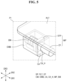
- FIG. 5 is an enlarged perspective view illustrating portion P 1 of FIG. 4 .
- FIG. 6 is an enlarged plan view illustrating portion P 2 of FIG. 4 .
- FIG. 7 is a cross-sectional view taken along line A-A′ of FIG. 6 .
- FIG. 8 is a cross-sectional view taken along line B-B′ of FIG. 6 .
- FIG. 9 is a cross-sectional view with an enlarged callout illustrating an embodiment of an elastic member when the display device is in an unfolded position.
- FIG. 10 is a cross-sectional view with an enlarged callout illustrating an embodiment of an elastic member when the display device is in an unfolded position.
- the illustrated embodiments are to be understood as providing illustrative features of varying detail of some ways in which the inventive concepts may be implemented in practice. Therefore, unless otherwise specified, the features, components, modules, layers, films, panels, regions, and/or aspects, etc. (hereinafter individually or collectively referred to as “elements”), of the various embodiments may be otherwise combined, separated, interchanged, and/or rearranged without departing from the inventive concepts.
- an element such as a layer
- it may be directly on, connected to, or coupled to the other element or layer or intervening elements or layers may be present.
- an element or layer is referred to as being “directly on,” “directly connected to,” or “directly coupled to” another element or layer, there are no intervening elements or layers present.
- the term “connected” may refer to physical, electrical, and/or fluid connection, with or without intervening elements.
- the D 1 -axis, the D 2 -axis, and the D 3 -axis are not limited to three axes of a rectangular coordinate system, such as the x, y, and z-axes, and may be interpreted in a broader sense.
- the D 1 -axis, the D 2 -axis, and the D 3 -axis may be perpendicular to one another, or may represent different directions that are not perpendicular to one another.
- a first direction DR 1 , a second direction DR 2 , and a third direction DR 3 intersect each other in different directions.
- the first direction DR 1 may be a width direction
- the second direction DR 2 may be a longitudinal direction
- the third direction DR 3 may be a height direction (thickness direction).
- Each of the first direction DR 1 , the second direction DR 2 , and the third direction DR 3 may include two or more directions.
- the third direction DR 3 may include an upward direction and a downward direction.
- one surface, which faces in the upward direction, of a member may be referred to as an upper surface thereof and the other surface, which faces in the downward direction, of the member may be referred to as a lower surface.
- the directions are only exemplary and relative and are not limited thereto.
- “at least one of X, Y, and Z” and “at least one selected from the group consisting of X, Y, and Z” may be construed as X only, Y only, Z only, or any combination of two or more of X, Y, and Z, such as, for instance, XYZ, XYY, YZ, and ZZ.
- the term “and/or” includes any and all combinations of one or more of the associated listed items.
- Spatially relative terms such as “beneath,” “below,” “under,” “lower,” “above,” “upper,” “over,” “higher,” “side” (e.g., as in “sidewall”), and the like, may be used herein for descriptive purposes, and, thereby, to describe one elements relationship to another element(s) as illustrated in the drawings.
- Spatially relative terms are intended to encompass different orientations of an apparatus in use, operation, and/or manufacture in addition to the orientation depicted in the drawings. For example, if the apparatus in the drawings is turned over, elements described as “below” or “beneath” other elements or features would then be oriented “above” the other elements or features.
- the term “below” can encompass both an orientation of above and below.
- the apparatus may be otherwise oriented (e.g., rotated 90 degrees or at other orientations), and, as such, the spatially relative descriptors used herein interpreted accordingly.
- FIG. 1 is a perspective view illustrating an embodiment of a display device constructed according to the principles of the invention.
- FIG. 2 is a perspective view illustrating a folded position of the display device of FIG. 1 .
- FIG. 3 is an exploded perspective view illustrating the display device of FIG. 1 .
- a display device 1 may include one of various devices configured to display screens or images.
- the display device 1 may include or take the form of, for example, a smartphone, a mobile phone, a tablet personal computer (PC), a personal digital assistant (PDA), a portable multimedia player (PMP), a television set, a game machine, a wrist watch type electronic device, a head mounted display, a monitor of a PC, a notebook computer, a car navigation system, a dashboard, a digital camera, a camcorder, an outdoor billboard, an electronic sign, various medical devices, various inspection devices, various home appliances including display areas (DPAs), such as a refrigerator and a washing machine, and the Internet of Things device but is not limited thereto.
- DPAs display areas
- the display device 1 may have a generally rectangular shape having two short sides in the first direction DR 1 , two long sides in the second direction DR 2 , and four corners CN when viewed from above.
- the shape of the display device 1 is not limited thereto, and the display device 1 may have one of various shapes such as a generally square shape, a generally round shape, and a generally rhombus shape.
- the display device 1 may be a foldable device which is foldable and unfoldable.
- the display device 1 may be folded or unfolded with respect to a folding axis FX extending in the second direction DR 2 .
- the folding axis FX may be incorporated in at least one rotatable shaft.
- the display device 1 may include a folding area FA, a first non-folding area NFA 1 , and a second non-folding area NFA 2 .
- the first non-folding area NFA 1 , the folding area FA, and the second non-folding area NFA 2 may be arranged sequentially in the first direction DR 1 .
- the folding area FA may be an area which is bent or folded when the display device 1 is folded, and the first non-folding area NFA 1 and the second non-folding area NFA 2 may be areas which are not bent or folded even when the display device 1 is folded.
- the display device 1 may be completely folded so that an angle between the first non-folding area NFA 1 and the second non-folding area NFA 2 becomes about 0° or about 360°, partially folded so that the angle between the first non-folding area NFA 1 and the second non-folding area NFA 2 becomes greater than about 0° and less than about 180°, or unfolded so that the angle between the first non-folding area NFA 1 and the second non-folding area NFA 2 becomes about 180°.
- the display device 1 may be in-folded. As illustrated in FIG. 2 , the term “in-folded” may denote “being folded such that an upper surface of a module in the form of a display module DM, which will be described below, is not exposed to the outside.”
- the upper surface of the display module DM may be a surface on which an image or video is displayed.
- some of the display module DM disposed in the first non-folding area NFA 1 may face other parts of the display module DM disposed in the second non-folding area NFA 2 .
- the display device 1 may also be out-folded or may be in-folded or out-folded.
- the term “out-folded” may denote “being folded so that the upper surface of the display module DM is exposed to the outside.”
- the display device 1 may include the flexible display module DM and a foldable part in the form of a foldable member FM disposed under the display module DM and supporting the display module DM.
- the display module DM may extend substantially across the first non-folding area NFA 1 , the folding area FA, and the second non-folding area NFA 2 of the display device 1 .
- the display module DM may be folded or unfolded by the foldable member FM.
- the display module DM may have a generally rectangular shape extending in the first direction DR 1 when viewed from above but is not limited thereto.
- the display module DM may include a display panel DP and a first support in the form of a support plate SP supporting the display panel DP.
- the display panel DP having four corners CN may display an image or video.
- the display panel DP may take the form of, but is not limited to a self-luminous display panel such as an organic light-emitting diode (OLED) display panel, an inorganic light-emitting (inorganic EL) display panel, a quantum dot light-emitting (QLED) display panel, a micro light emitting-diode (LED) display panel (micro-LED), a nano LED (nano-LED) display panel, a plasma display panel (PDP), a field emission display (FED) panel, or a cathode ray tube (CRT) display panel or a light-receiving display panel such as a liquid crystal display (LCD) panel or a electrophoretic display (EPD) panel.
- OLED organic light-emitting diode
- the support plate SP may be disposed on the display panel DP and overlap the display panel DP in the thickness direction.
- the support plate SP may be disposed on a lower surface of the display panel DP.
- the lower surface of the display panel DP may be a surface opposite to an upper surface, on which an image is displayed, of the display panel DP.
- the support plate SP may be provided as a plate-shaped member having a generally rectangular shape when viewed from above.
- the support plate SP may be directly attached to the lower surface of the display panel DP but is not limited thereto.
- the support plate SP may have flexibility so that the support plate SP may be integrally folded or unfolded with the display panel DP.
- the support plate SP may be formed as, for example, a thin metal plate.
- a pattern to facilitate folding and reduce bending stiffness may be formed in the folding area FA.
- the foldable member FM may include a first body in the form of a first body frame BF 1 , a second body in the form of a second body frame BF 2 , a first cover frame CPT 1 , a second cover frame CPT 2 , and a hinge member HM.
- first body or the second body may be referred to, independently, as a body and the first cover or the second cover may be referred to, independently, as a cover.
- the first body frame BF 1 and the second body frame BF 2 may be disposed on a lower surface of the support plate SP.
- the first body frame BF 1 may be substantially disposed in the first non-folding area NFA 1
- the second body frame BF 2 may be substantially disposed in the second non-folding area NFA 2
- the first body frame BF 1 and the second body frame BF 2 may be symmetrically disposed with respect to the folding area FA (folding axis FX).
- the first body frame BF 1 and the second body frame BF 2 may have substantially the same or similar structures.
- the first cover frame CPT 1 and the second cover frame CPT 2 may be disposed in the first body frame BF 1 and the second body frame BF 2 .
- the first cover frame CPT 1 and the second cover frame CPT 2 may cover an upper portion of the first body frame BF 1 and an upper portion of the second body frame BF 2 , respectively.
- the first cover frame CPT 1 and the second cover frame CPT 2 may be symmetrically disposed with respect to the folding area FA (folding axis FX).
- the first body frame BF 1 and the second body frame BF 2 may have substantially the same or similar structures.
- the hinge member HM may connect the first body frame BF 1 and the second body frame BF 2 .
- the hinge member HM may be disposed in the folding area FA.
- the first body frame BF 1 may be rotatably connected to one side of the hinge member HM, and the second body frame BF 2 may be connected to the other side of the hinge member HM.
- the first body frame BF 1 and the second body frame BF 2 may rotate in different directions about the hinge member HM.
- the display device 1 may further include a bezel member BZ disposed along an edge of the display module DM.
- the bezel member BZ may cover a gap G (see FIG. 10 ) generated between the display module DM and the foldable member FM when the display device 1 is folded or unfolded.
- the display device 1 may further include a first back cover BC 1 (see FIGS. 7 to 10 ) disposed on a lower surface of the first body frame BF 1 and a second back cover BC 2 (see FIGS. 9 to 10 ) disposed on a lower surface of the second body frame BF 2 .
- FIG. 4 is an exploded perspective view illustrating an embodiment of the support member and foldable member of the display device of FIG. 3 .
- FIG. 5 is an enlarged perspective view illustrating portion P 1 of FIG. 4 .
- FIG. 6 is an enlarged plan view illustrating portion P 2 of FIG. 4 .
- FIG. 7 is a cross-sectional view taken along line A-A′ of FIG. 6 .
- FIG. 8 is a cross-sectional view taken along line B-B′ of FIG. 6 .
- the support plate SP may include a plate part PLT and a plurality of couplers in the form of coupling parts CP.
- the plate part PLT may be disposed on the foldable member FM. As illustrated in FIGS. 3 and 4 , an upper surface of the plate part PLT may face the display panel DP, and a lower surface of the plate part PLT may face the foldable member FM.
- the plate part PLT may be provided as a generally plate shaped member having a substantially rectangular shape when viewed from above. The plate part PLT may overlap and cover the first body frame BF 1 , the hinge member HM, the second body frame BF 2 , the first cover frame CPT 1 , and the second cover frame CPT 2 in the thickness direction.
- the plate part PLT may be directly disposed on the first cover frame CPT 1 , the second cover frame CPT 2 , and the hinge member HM.
- other members for example, double-sided tape, a pressure-sensitive adhesive, an optically transparent adhesive, or an adhesive member such as a resin may not be interposed between the plate part PLT and the first cover frame CPT 1 , between the plate part PLT and the second cover frame CPT 2 , and between the plate part PLT and the hinge member HM.
- the display module DM and the foldable member FM are not attached by the adhesive member or the like but are coupled by the plurality of coupling parts CP, when the display device 1 is folded, the display module DM may slidably move with respect to the foldable member FM in a direction intersecting, e.g., orthogonal to, the thickness direction. Accordingly, when the display device 1 is folded, stresses generated due to a change in the gap between the members, a change in relative position between the members, or the like may be released.
- the direction intersecting the thickness direction may be a direction generally parallel to an upper surface of the foldable member FM.
- the plurality of coupling parts CP may be disposed on the lower surface of the plate part PLT.
- the plurality of coupling parts CP may protrude from the lower surface of the plate part PLT.
- the plurality of coupling parts CP may be disposed in edge portions of the plate part PLT.
- four coupling parts CP may be disposed on four corners of the plate part PLT, which generally correspond to the four corners CN of the display module DM.
- the four corners may be formed by two long sides which extend in the first direction DR 1 meeting two short sides extending in the second direction DR 2 of the plate part PLT.
- the embodiments are not limited thereto, and positions of the plurality of coupling parts CP may be variously changed.
- the positions of the plurality of coupling parts CP may be disposed close to central portions of the short sides extending in the second direction DR 2 and/or central portions of the long sides extending in the first direction DR 1 of the plate part PLT or a central region of the plate part PLT.
- the plurality of coupling parts CP may be inserted into a plurality of openings OP of the foldable member FM, which will be described below, to press the foldable member FM in a direction in which the hinge member HM is positioned so as to apply a tensile force to the plate part PLT and the display panel DP disposed on the plate part PLT.
- the first body frame BF 1 , the second body frame BF 2 , the hinge member HM, the first cover frame CPT 1 , and the second cover frame CPT 2 may be disposed on the lower surface of the plate part PLT.
- the first body frame BF 1 and the second body frame BF 2 may have sides which form recesses d and define inner spaces ISS 1 and ISS 2 (see FIGS. 4 and 7 to 10 ) in which electronic components are mounted.
- the first cover frame CPT 1 and the second cover frame CPT 2 may be disposed to, respectively, cover almost all the inner spaces ISS 1 and ISS 2 of the first body frame BF 1 and the second body frame BF 2 .
- the first cover frame CPT 1 and the second cover frame CPT 2 may cover, respectively, a portion of the inner space of the first body frame BF 1 and a portion of the inner space of the second body frame BF 2 .
- a plurality of openings OP may be formed in the upper surface of the foldable member FM facing the support plate SP.
- the portion of the inner space ISS 1 of the first body frame BF 1 and the portion of the inner space ISS 2 of the second body frame BF 2 may be exposed upward through the plurality of openings OP.
- the plurality of openings OP may be formed between the first body frame BF 1 and the first cover frame CPT 1 and between the second body frame BF 2 and the second cover frame CPT 2 but are not limited thereto.
- the plurality of openings OP may be formed to penetrate through the first cover frame CPT 1 or the second cover frame CPT 2 .
- the plurality of openings OP may be formed at positions facing a plurality of protrusions CMB projecting downwardly from the support plate PLT as discussed in connection with FIG. 5 .
- the plurality of openings OP may receive the plurality of protrusions CMB.
- the plurality of four openings OP may be formed in four corners of the upper surface of the foldable member FM.
- the plurality of openings OP are not limited thereto and may be disposed close to the long sides extending in the first direction DR 1 and/or the short sides extending in the second direction DR 2 of the foldable member FM.
- corner portions P 1 and P 2 illustrated at a left side in the FIG. 4 will be mainly described of the corner portions, which are disposed in the first non-folding area NFA 1 , of the display device 1 .
- Other corner portions of the display device 1 may also substantially have the same or a similar structure of the corner portion of the left upper end of the display device 1 , so such descriptions will be omitted to avoid redundancy.
- both corners of the first non-folding area NFA 1 may have a symmetrical structure with respect to an arbitrary axis bisecting the display device 1 in the first direction DR 1
- both corners of the first non-folding area NFA 1 and both corners of the second non-folding area NFA 2 may have a symmetrical structure with respect to the hinge member HM and/or folding axis FX (see FIG. 1 ).
- the coupling part CP may include a housing in the form of the protrusion CMB, a movable part in the form of a movable member MP, and an elastic part in the form or elastic member EM.
- the protrusion CMB may be disposed on the corner of the plate part PLT and may be formed to project downwardly from the lower surface of the plate part PLT. As illustrated in FIG. 6 , the protrusion CMB may be received in the opening OP formed between the first cover frame CPT 1 and the first body frame BF 1 .
- the protrusion CMB may have an inner space ISS of which one side is open. At least a portion of the movable member MP and the elastic member EM may be received in the protrusion CMB.
- the protrusion CMB may denote a chamber of which one side is open and which receives the portion of the movable member MP and the elastic member EM.
- the coupling part CP may further include a capping member CA which covers one open side of the protrusion CMB.
- the protrusion CMB and the capping member CA may include a first through hole CMB_H and a second through hole CA_H through which the movable member MP passes.
- the first through hole CMB_H and the second through hole CA_H may be arranged in a linear direction of the movable member MP along its longitudinal axis to guide the sliding movement of the movable member MP.
- the diameter of the first through hole CMB_H and the diameter of the second through hole CA_H may be greater than or equal to a diameter of a substantially cylindrically-shaped portion of a cylinder part CY, which forms part of the movable member MP.
- the size of the first through hole CMB_H and a size of the second through hole CA_H may be less than a size of a stopper part STP.
- the movable member MP may be slidably supported by and movably coupled to the protrusion CMB.
- the movable member MP may be inserted into the protrusion CMB.
- the movable member MP may be a generally rod or pin shaped member of having an outer circumferential surface extending in a radial direction.
- the movable member MP may include the cylinder part CY and the stopper part STP.
- the cylinder part CY may have a generally cylindrical shape extending in the first direction DR 1 .
- a portion of the cylinder part CY may be received in the protrusion CMB, and both ends thereof may be exposed to the outside of the protrusion CMB.
- the exposed length of each of the ends of the cylinder part CY may be changed.
- the stopper part STP may extend outwardly from an outer circumferential surface of the cylinder part CY.
- the stopper part STP may be received in the protrusion CMB.
- the stopper part STP may come into contact with the capping member CA to restrict the movable distance of the movable member MP.
- the first body frame BF 1 may include the inner space ISS 1 , which, may be covered by the first cover frame CPT 1 . A portion of the inner space close to a corner of the first body frame BF 1 may not be covered by the first cover frame CPT 1 so as to form the opening OP.
- the opening OP may be covered by the plate part PLT.
- the protrusion CMB may be received in the inner space ISS 1 of the first body frame BF 1 through the opening OP.
- the first cover frame CPT 1 may include a generally flat part CPT 1 _F and a bent part CPT 1 _B, as shown in FIG. 7 .
- the generally flat part CPT 1 _F may be disposed on the lower surface of the plate part PLT.
- the generally flat part CPT 1 _F may be provided as a generally plate shaped member generally parallel to the first direction DR 1 and the second direction DR 2 .
- the generally flat part CPT 1 _F may flatly extend in a substantially horizontal direction to cover the inner space of the first body frame BF 1 .
- the generally flat part CPT 1 _F may not be disposed at a corner portion of the first body frame BF 1 so that the opening OP is formed therein.
- a corner portion of the generally flat part CPT 1 _F may be recessed inward from the generally flat part CPT 1 _F so that an edge thereof has a generally L shape when viewed from above.
- a lower surface of the generally flat part CPT 1 _F may be seated on an upper surface of a second support in the form of a support part PST.
- a portion of the generally flat part CPT 1 _F may be interposed between the support part PST and the plate part PLT.
- the bent part CPT 1 _B may be connected to the generally flat part CPT 1 _F, be bent from the generally flat part CPT 1 _F, and extend in the third direction DR 3 .
- the third direction DR 3 may be a substantially vertical direction.
- the inner space of the first body frame BF 1 may not be completely covered by the first cover frame CPT 1 , and the opening OP accommodating the protrusion CMB and the movable member MP may be formed between an inner side surface forming the inner space ISS 1 of the first body frame BF 1 and the bent part CPT 1 _B.
- the bent part CPT 1 _B may be disposed on a side surface of the protrusion CMB extending in the third direction DR 3 .
- a third through hole CPT 1 _H through which the movable member MP passes may be formed in the bent part CPT 1 _B, and the movable member MP may be in direct contact with the side surface of the protrusion CMB through the third through hole CPT 1 _H.
- the third through hole CPT 1 _H may fix a position of an end portion of the movable member MP in contact with the support part PST.
- an upper surface of a portion in which the bent part CPT 1 _B and the generally flat part CPT 1 _F are connected includes a generally curved surface having a generally convex curvature outward, the display module DM and the foldable member FM may be easily assembled.
- the support part PST may be disposed under the generally flat part CPT 1 _F.
- the support part PST may be in direct contact with the lower surface of the generally flat part CPT 1 _F to support the generally flat part CPT 1 _F.
- the support part PST may support one side of the movable member MP.
- the support part PST may restrict movement of the movable member MP in the first direction DR 1 .
- the first direction DR 1 may a direction toward the hinge member HM.
- the support part PST may fix the relative position of the movable member MP with respect to the foldable member FM (first body frame BF 1 ) so that a tensile force may be applied to the plate part PLT and the display panel DP disposed on the plate part PLT due to the restoring force of the elastic member EM.
- the relative position of the movable member MP with respect to the display module DM protrusion CMB
- the foldable member FM may further include a coupling hole SCW_H penetrating through the support part PST and the generally flat part CPT 1 _F in the thickness direction.
- a coupling member such as a screw may be inserted into the coupling hole SCW_H to fix the first cover frame CPT 1 to the first body frame BF 1 .
- the embodiments are not limited thereto, and the first cover frame CPT 1 and the first body frame BF 1 may be coupled together in one of various manners.
- the elastic member EM may be received in the protrusion CMB.
- the elastic member EM may be interposed between an inner side surface ISSP of the protrusion CMB and the stopper part STP of the movable member MP.
- One side OSS of the elastic member EM may be supported by the inner side surface ISSP forming the inner space ISS of the protrusion CMB, and the other side OTS of the elastic member EM may be supported by the stopper part STP.
- One side SS of the movable member MP may be supported by the support part PST, and the elastic member EM may push an inner sidewall of the protrusion CMB in a direction away from the hinge member HM (depicted in FIG. 4 ). Accordingly, a tensile force may be applied to the plate part PLT integrally connected to the protrusion CMB and the display panel DP attached to the plate part PLT to reduce creasing dur to folding and unfolding of the display.
- the elastic member EM may be provided as a part formed of an elastic material capable of providing a restoring force.
- the elastic member EM may be a spring.
- the other side of the movable member MP may pass through the spring so that the spring may surround the outer circumferential surface of the movable member MP.
- the elastic member EM may be received in the protrusion CMB in a state in which the elastic member EM is compressed to provide a predetermined restorative force.
- the elastic member EM may always provide the restorative force to elongate the display panel DP regardless of folding of the display device 1 . That is, the display device 1 according to one embodiment may allow the tensile force to be continuously applied to the display panel DP so that folding creases of the display panel DP due to repeated folding may be reduced.
- FIG. 9 is a cross-sectional view with an enlarged callout illustrating an embodiment of an elastic member when the display device is in an unfolded position.
- FIG. 10 is a cross-sectional view with an enlarged callout illustrating an embodiment of an elastic member when the display device is in an unfolded position. Repetitive descriptions of elements discussed above will be omitted to avoid redundancy.
- the movable member MP may slidably move with respect to the protrusion CMB in the first direction DR 1 .
- the first direction DR 1 may be a direction intersecting the thickness direction.
- the first direction DR 1 may be a direction substantially parallel to a direction in which the upper surface (lower surface) of the display panel DP extends.
- the movable member MP may move in a direction opposite to a direction in which the hinge member HM is positioned and/or in which the elastic member EM is compressed.
- the movable member MP may move in the direction in which the hinge member HM is positioned and/or in which the elastic member EM is elongated.
- the length of the elastic member EM retained in the protrusion CMB may be changed.
- the elastic member EM in a case in which the display device 1 is in the unfolded state, the elastic member EM has a first length L 1 , and in a case in which the display device 1 is in the folded state, the elastic member EM may have a second length L 2 , less than the first length L 1 , as the elastic member is compressed and the moving member MP has a greater length extending outside the protrusion CMB. That is, the length of the elastic member EM may be reduced when the display panel DP is folded and may be elongated when the display device 1 is unfolded. According to a specific configuration of the display device 1 , the second length L 2 may be greater than the first length L 1 .
- the display module DM when the display device 1 is folded, the display module DM may be slidably moved by a small distance with respect to the foldable member FM.
- the gap G may be formed between the edge of the display module DM (display panel DP) and the foldable member FM (inner side surface of the first body frame BF 1 ).
- the bezel member BZ may be disposed across the display panel DP and the first body frame BF 1 to cover the gap G.
- the gap G may be formed when the display device 1 is unfolded.
- Display devices having a foldable display panel constructed according to the principles and embodiments of the invention can reduce folding creases, which are generated due to repeated folding.
Abstract
Description
Claims (17)
Applications Claiming Priority (2)
| Application Number | Priority Date | Filing Date | Title |
|---|---|---|---|
| KR10-2020-0140414 | 2020-10-27 | ||
| KR1020200140414A KR20220056294A (en) | 2020-10-27 | 2020-10-27 | Display device |
Publications (2)
| Publication Number | Publication Date |
|---|---|
| US20220132689A1 US20220132689A1 (en) | 2022-04-28 |
| US11805604B2 true US11805604B2 (en) | 2023-10-31 |
Family
ID=81256746
Family Applications (1)
| Application Number | Title | Priority Date | Filing Date |
|---|---|---|---|
| US17/353,553 Active 2041-07-01 US11805604B2 (en) | 2020-10-27 | 2021-06-21 | Display device |
Country Status (3)
| Country | Link |
|---|---|
| US (1) | US11805604B2 (en) |
| KR (1) | KR20220056294A (en) |
| CN (1) | CN114495705A (en) |
Citations (24)
| Publication number | Priority date | Publication date | Assignee | Title |
|---|---|---|---|---|
| KR20040059817A (en) | 2002-12-30 | 2004-07-06 | 엘지.필립스 엘시디 주식회사 | Flat panel display module |
| US20140111954A1 (en) * | 2012-10-19 | 2014-04-24 | Samsung Display Co., Ltd. | Foldable display device |
| US9173288B1 (en) * | 2014-09-01 | 2015-10-27 | Lg Display Co., Ltd. | Foldable display apparatus |
| US9348362B2 (en) * | 2013-02-08 | 2016-05-24 | Samsung Electronics Co., Ltd. | Flexible portable terminal |
| KR20170052474A (en) | 2015-10-29 | 2017-05-12 | 엘지디스플레이 주식회사 | Display device |
| KR20170057500A (en) | 2015-11-16 | 2017-05-25 | 삼성디스플레이 주식회사 | Foldable display apparatus |
| US20170290179A1 (en) * | 2016-03-31 | 2017-10-05 | Lenovo (Beijing) Limited | Deformable surface apparatus, electronic device, and method |
| US9791892B2 (en) * | 2014-06-27 | 2017-10-17 | Samsung Electronics Co., Ltd. | Foldable device |
| US9844251B2 (en) * | 2014-06-18 | 2017-12-19 | Au Optronics Corp. | Foldable display device |
| US20180213663A1 (en) * | 2017-01-26 | 2018-07-26 | Guangdong Oppo Mobile Telecommunications Corp., Ltd. | Capping member, housing assembly, and electronic |
| US10209746B2 (en) | 2016-03-29 | 2019-02-19 | Samsung Display Co., Ltd. | Foldable display device |
| US20190075669A1 (en) | 2018-06-28 | 2019-03-07 | Shanghai Tianma AM-OLED Co., Ltd. | Bending apparatus and display device |
| US20190132974A1 (en) | 2017-10-26 | 2019-05-02 | Wuhan China Star Optoelectronics Semiconducter Display Technology Co., Ltd. | Middle frame and flexible display device |
| US20190306290A1 (en) * | 2015-12-10 | 2019-10-03 | Lg Electronics Inc. | Mobile terminal |
| US10474196B2 (en) * | 2017-08-07 | 2019-11-12 | Wuhan China Star Optoelectronics Semiconductor Display Technology Co., Ltd. | Display device |
| US10520992B1 (en) * | 2018-12-06 | 2019-12-31 | Jarllytec Co., Ltd. | Hinge module for a foldable type device |
| US20200170127A1 (en) * | 2018-11-23 | 2020-05-28 | Lg Display Co., Ltd. | Foldable display device |
| US20200253068A1 (en) * | 2019-01-31 | 2020-08-06 | Lg Electronics Inc. | Flexible display device |
| US20200253069A1 (en) * | 2019-01-31 | 2020-08-06 | Lg Electronics Inc. | Flexible display device |
| US11044825B1 (en) * | 2019-12-18 | 2021-06-22 | Wuhan China Star Optoelectronics Semiconductor Display Technology Co., Ltd. | Foldable display device |
| US20210223820A1 (en) * | 2020-01-20 | 2021-07-22 | Lg Electronics Inc. | Mobile terminal |
| US20210360799A1 (en) * | 2019-07-30 | 2021-11-18 | Wuhan Chian Star Optoeletronics Semiconductor Display Technology Co., Ltd. | Foldable display device |
| US20210365074A1 (en) * | 2018-11-02 | 2021-11-25 | Hewlett-Packard Development Company, L.P. | Magnetic suspensions for displays |
| US11240920B2 (en) * | 2017-12-28 | 2022-02-01 | Lg Display Co., Ltd. | Foldable display device having adjustable support units retreatable into recessed portions of set frames |
-
2020
- 2020-10-27 KR KR1020200140414A patent/KR20220056294A/en active Search and Examination
-
2021
- 2021-06-21 US US17/353,553 patent/US11805604B2/en active Active
- 2021-08-26 CN CN202110987068.3A patent/CN114495705A/en active Pending
Patent Citations (26)
| Publication number | Priority date | Publication date | Assignee | Title |
|---|---|---|---|---|
| KR20040059817A (en) | 2002-12-30 | 2004-07-06 | 엘지.필립스 엘시디 주식회사 | Flat panel display module |
| US20140111954A1 (en) * | 2012-10-19 | 2014-04-24 | Samsung Display Co., Ltd. | Foldable display device |
| US9348362B2 (en) * | 2013-02-08 | 2016-05-24 | Samsung Electronics Co., Ltd. | Flexible portable terminal |
| US9844251B2 (en) * | 2014-06-18 | 2017-12-19 | Au Optronics Corp. | Foldable display device |
| US9791892B2 (en) * | 2014-06-27 | 2017-10-17 | Samsung Electronics Co., Ltd. | Foldable device |
| US9173288B1 (en) * | 2014-09-01 | 2015-10-27 | Lg Display Co., Ltd. | Foldable display apparatus |
| KR20170052474A (en) | 2015-10-29 | 2017-05-12 | 엘지디스플레이 주식회사 | Display device |
| US10694623B2 (en) | 2015-11-16 | 2020-06-23 | Samsung Display Co., Ltd. | Foldable display apparatus |
| KR20170057500A (en) | 2015-11-16 | 2017-05-25 | 삼성디스플레이 주식회사 | Foldable display apparatus |
| US20190306290A1 (en) * | 2015-12-10 | 2019-10-03 | Lg Electronics Inc. | Mobile terminal |
| US10209746B2 (en) | 2016-03-29 | 2019-02-19 | Samsung Display Co., Ltd. | Foldable display device |
| US20170290179A1 (en) * | 2016-03-31 | 2017-10-05 | Lenovo (Beijing) Limited | Deformable surface apparatus, electronic device, and method |
| US20180213663A1 (en) * | 2017-01-26 | 2018-07-26 | Guangdong Oppo Mobile Telecommunications Corp., Ltd. | Capping member, housing assembly, and electronic |
| US10474196B2 (en) * | 2017-08-07 | 2019-11-12 | Wuhan China Star Optoelectronics Semiconductor Display Technology Co., Ltd. | Display device |
| US20190132974A1 (en) | 2017-10-26 | 2019-05-02 | Wuhan China Star Optoelectronics Semiconducter Display Technology Co., Ltd. | Middle frame and flexible display device |
| US11240920B2 (en) * | 2017-12-28 | 2022-02-01 | Lg Display Co., Ltd. | Foldable display device having adjustable support units retreatable into recessed portions of set frames |
| US20190075669A1 (en) | 2018-06-28 | 2019-03-07 | Shanghai Tianma AM-OLED Co., Ltd. | Bending apparatus and display device |
| US20210365074A1 (en) * | 2018-11-02 | 2021-11-25 | Hewlett-Packard Development Company, L.P. | Magnetic suspensions for displays |
| US11353934B2 (en) * | 2018-11-02 | 2022-06-07 | Hewlett-Packard Development Company, L.P. | Magnetic suspensions for displays |
| US20200170127A1 (en) * | 2018-11-23 | 2020-05-28 | Lg Display Co., Ltd. | Foldable display device |
| US10520992B1 (en) * | 2018-12-06 | 2019-12-31 | Jarllytec Co., Ltd. | Hinge module for a foldable type device |
| US20200253068A1 (en) * | 2019-01-31 | 2020-08-06 | Lg Electronics Inc. | Flexible display device |
| US20200253069A1 (en) * | 2019-01-31 | 2020-08-06 | Lg Electronics Inc. | Flexible display device |
| US20210360799A1 (en) * | 2019-07-30 | 2021-11-18 | Wuhan Chian Star Optoeletronics Semiconductor Display Technology Co., Ltd. | Foldable display device |
| US11044825B1 (en) * | 2019-12-18 | 2021-06-22 | Wuhan China Star Optoelectronics Semiconductor Display Technology Co., Ltd. | Foldable display device |
| US20210223820A1 (en) * | 2020-01-20 | 2021-07-22 | Lg Electronics Inc. | Mobile terminal |
Also Published As
| Publication number | Publication date |
|---|---|
| US20220132689A1 (en) | 2022-04-28 |
| CN114495705A (en) | 2022-05-13 |
| KR20220056294A (en) | 2022-05-06 |
Similar Documents
| Publication | Publication Date | Title |
|---|---|---|
| US11099691B2 (en) | Display device | |
| US11119534B2 (en) | Foldable display device | |
| US10503210B2 (en) | Folding device of foldable display and display device having the same | |
| US10925176B2 (en) | Display apparatus | |
| US10368452B2 (en) | Foldable display device | |
| US10963012B2 (en) | Display device | |
| US11073870B2 (en) | Display device | |
| KR20190001864A (en) | Foldable display apparatus | |
| US7515406B2 (en) | Foldable multi-display apparatus and method thereof | |
| US11792946B2 (en) | Display device having a folding area | |
| US9164547B1 (en) | Foldable display apparatus | |
| US9651987B2 (en) | Portable display device | |
| EP3657766B1 (en) | Display device | |
| CN111223403B (en) | Display device | |
| US11605796B2 (en) | Display device | |
| US11178779B2 (en) | Display device | |
| US11726527B2 (en) | Display device | |
| CN109345987A (en) | Display panel and display device | |
| US11940846B2 (en) | Display device | |
| US20220269307A1 (en) | Display device | |
| US11599156B2 (en) | Display device | |
| US11805604B2 (en) | Display device | |
| US11805607B2 (en) | Display device |
Legal Events
| Date | Code | Title | Description |
|---|---|---|---|
| AS | Assignment |
Owner name: SAMSUNG DISPLAY CO., LTD., KOREA, REPUBLIC OF Free format text: ASSIGNMENT OF ASSIGNORS INTEREST;ASSIGNOR:LEE, JI HEON;REEL/FRAME:056709/0293 Effective date: 20210329 |
|
| FEPP | Fee payment procedure |
Free format text: ENTITY STATUS SET TO UNDISCOUNTED (ORIGINAL EVENT CODE: BIG.); ENTITY STATUS OF PATENT OWNER: LARGE ENTITY |
|
| STPP | Information on status: patent application and granting procedure in general |
Free format text: DOCKETED NEW CASE - READY FOR EXAMINATION |
|
| STPP | Information on status: patent application and granting procedure in general |
Free format text: NON FINAL ACTION MAILED |
|
| STPP | Information on status: patent application and granting procedure in general |
Free format text: RESPONSE TO NON-FINAL OFFICE ACTION ENTERED AND FORWARDED TO EXAMINER |
|
| STPP | Information on status: patent application and granting procedure in general |
Free format text: PUBLICATIONS -- ISSUE FEE PAYMENT VERIFIED |
|
| STCF | Information on status: patent grant |
Free format text: PATENTED CASE |