US1180098A - Soldering-iron. - Google Patents
Soldering-iron. Download PDFInfo
- Publication number
- US1180098A US1180098A US6913315A US6913315A US1180098A US 1180098 A US1180098 A US 1180098A US 6913315 A US6913315 A US 6913315A US 6913315 A US6913315 A US 6913315A US 1180098 A US1180098 A US 1180098A
- Authority
- US
- United States
- Prior art keywords
- hot point
- holder
- combustion chamber
- soldering
- soldering iron
- Prior art date
- Legal status (The legal status is an assumption and is not a legal conclusion. Google has not performed a legal analysis and makes no representation as to the accuracy of the status listed.)
- Expired - Lifetime
Links
- XEEYBQQBJWHFJM-UHFFFAOYSA-N iron Substances [Fe] XEEYBQQBJWHFJM-UHFFFAOYSA-N 0.000 title description 22
- 229910052742 iron Inorganic materials 0.000 title description 12
- 238000002485 combustion reaction Methods 0.000 description 17
- 238000005476 soldering Methods 0.000 description 11
- 239000000446 fuel Substances 0.000 description 7
- 239000007789 gas Substances 0.000 description 7
- 238000010276 construction Methods 0.000 description 4
- 238000004519 manufacturing process Methods 0.000 description 1
Images
Classifications
-
- B—PERFORMING OPERATIONS; TRANSPORTING
- B23—MACHINE TOOLS; METAL-WORKING NOT OTHERWISE PROVIDED FOR
- B23K—SOLDERING OR UNSOLDERING; WELDING; CLADDING OR PLATING BY SOLDERING OR WELDING; CUTTING BY APPLYING HEAT LOCALLY, e.g. FLAME CUTTING; WORKING BY LASER BEAM
- B23K3/00—Tools, devices, or special appurtenances for soldering, e.g. brazing, or unsoldering, not specially adapted for particular methods
- B23K3/02—Soldering irons; Bits
- B23K3/021—Flame-heated soldering irons
- B23K3/022—Flame-heated soldering irons using a gaseous fuel
Definitions
- My present invention is an improved soldering iron of the gas heated type, and has for its object to provide a soldering iron of relatively simple and inexpensive construction and comprising a hot point and. a holder therefor formed with a combustion chamber into which the body of the hot point extends, and having provisions for readily securing the hot point in, and releasing it from, the holder, and for securing an effective transfer of heat to the hot point directly from the burning gases and indirectly through the holder.
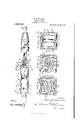
- Figure 1 is an elevation with parts in longitudinal section of my improved soldering ironv construction;
- Figs. 2, 3 and 4f are transverse sections taken on the lines 2 2, 3-3, and 4-4 respectively of Fig. 1.
- My improved soldering iron in the form shown in the drawings comprises a member A which forms the body portion of a holder in which the hot point B is releasably secured.
- the latter is rectangular in cross section and has its front end tapered in the usual manner.
- rl ⁇ he member A is formed with a front end portion A a rear end portion A2, and a pair of parallel, spaced apart i portions A3 connecting the two end portions.
- the front end portion A is formed with an axial passage way through which the hot point B extends.
- the front end portion A is also formed with beveled seats A4 for an opposed pair of clamping jaws C.
- the wedge shaped front end portions C of the clamping jaws C jam between the tapered seats At and the adjacent fiat sides of the hot point B to clamp the latter in place.
- the jaws are forced into the clamping position by means of a follower D which lits between the side portions A3 and is formed with sockets or grooves D3 in its front end to receive the correspondingly shaped rear ends C2 of the clamping jaws C.
- the member D is formed with an axial passage D enlarged at its rear end to form a socket D2 receiving the end of a fuel supply pipe F which is externally threaded and is screwed through a threaded axial passage way formed in the rear end portion A2 of the holder body.
- the tube E is shown as surrounded by the usual insulated hollow handle E2, and at its rear end the tube is formed with provisions E for the attachment of a fuel supply hose.
- the jaw members C are of a width to snugly fit between the opposed side portions A2, and unite with the latter to form the side walls of the combustion chamber which is generally rectangular in cross section and is closed at its rear end 'by the member D.
- the rear end of the hot point projects a considerable distance into the combustion chamber and advantageously as shown in Fig. 3, an appreciable clearance is provided between the portion of the hot point projecting into the combustion chamber and the adjacent wall of the latter.
- longitudinal grooves or channels A5 are formed in the inner wall of the passage way for the hot point and lead from the combustion chamber through the front end portion A of the holder.
- ASmall ports C3 may be formed, as shown, through the jaw members C adjacent their front end, to facilitate the ignition of the fuel supplied to the combustion chamber through the pipe E and the port D.
- the soldering iron shown is intended to be heated by the combustion of air and gas supplied to the combustion chamber A6 through the pipe E and the port D in the member D, in the proportion necessary for complete combustion.
- a roll of gauze F or equivalent means may be placed in the forward end of the tube E to chill the flame and to prevent it from striking back.
- the soldering iron construction described is obviously simple, and durable, and relatively inexpensive to manufacture.
- the hotv and dispoint may be readily connected to connected from the holder in any desired adjustment and when secured in place is held very rigidly and securely.
- the construction disclosed insures a highly eflicient .utilization of the heatgenerated in the conibustion chamber.
- the heat absorbed by -the walls of the combustion chamber is very l-argely transmitted vthe contact of the sponding use of other features.
- a gas heated soldering iron the combination with a hot point, of ⁇ a holder therefor comprising a body member formed with front and rear'end portions and a-pair of parallel spaced apart side' portions connecting said end portions, said front end portion being formed with a passage way for the hotpoint and said rear end portion being .formed with a threaded opening, a pair of clamping jaws cooperating with said 'front endfportion to clamp the hot point in place and uniting with said side'portions to form the ylateral walls of a combustion chamber, a follower engaging the rear ends of said jaws and uniting with said side portions to form the rear end of said combustion chamber, and a fuel supply pipe threaded through said threaded opening, and engaging said follower to advance said jaws and 'thereby clamp the hot point in place, said follower being formed with a passagethrough'which the fuel passes from said supply pipe into said chamber.
- f rIn a gas heated soldering iron, the combination with the hot point, of a holder therefor formed with a combustion cha1nber and a passage throughwhich the hot point projects into'said chamber, and comprising albody portion and movable clamping jaws uniting with said body portionrto form ⁇ a portion of the wall of said combustion spaceand to secure the hot point in saidpassage, and a pipe supplying fuel to saidy chamber rotatively mounted in said holder and adapted to tighten and release said jaws when turned relatively to the holder in one direction or the other.
Landscapes
- Engineering & Computer Science (AREA)
- Mechanical Engineering (AREA)
- Gas Burners (AREA)
Description
H. ZIMMERNIANN.
SOLDERING IRON.
APPLICATION FILED 0m29.191s.
L l Patented Apr. 18, 1916.
ffl
"i lll D Flifltl.
HANS ZIMMERMANN, 0F PHILADELPHIA, PENNSYLVANIA, ASSIGNOR T0 SGHUTTE & KOERTING COMPANY, OF PHILADELPHIA, PENNSYLVANIA, A CORPORATION OF PENNSYLVANIA.
SOLDERING-IRON.
To all whom t may concern:
Be it known that I, HANS ZIMMERMANN, a subject of the German Empire, residing in the city and county of Philadelphia, in the State of Pennsylvania, have invented certain new and useful Improvements in Soldering-irons, of which the following is a true and exact description, reference being had to the accompanying drawings, which form a part thereof.
My present invention is an improved soldering iron of the gas heated type, and has for its object to provide a soldering iron of relatively simple and inexpensive construction and comprising a hot point and. a holder therefor formed with a combustion chamber into which the body of the hot point extends, and having provisions for readily securing the hot point in, and releasing it from, the holder, and for securing an effective transfer of heat to the hot point directly from the burning gases and indirectly through the holder.
The various features of novelty which characterize my invention are pointed out with partioularity in the claims-annexed to and forming a part of this specification. For a better understanding of the invention, however, and the advantages possessed by it, reference should be had to the accompanying drawings and descriptive matter in which I have illustrated and described a preferred embodiment of my invention.
0f the drawings: Figure 1 is an elevation with parts in longitudinal section of my improved soldering ironv construction; Figs. 2, 3 and 4f are transverse sections taken on the lines 2 2, 3-3, and 4-4 respectively of Fig. 1.
My improved soldering iron in the form shown in the drawings, comprises a member A which forms the body portion of a holder in which the hot point B is releasably secured. The latter is rectangular in cross section and has its front end tapered in the usual manner. rl`he member A is formed with a front end portion A a rear end portion A2, and a pair of parallel, spaced apart i portions A3 connecting the two end portions. The front end portion A is formed with an axial passage way through which the hot point B extends. The front end portion A is also formed with beveled seats A4 for an opposed pair of clamping jaws C. The
Specification of Letters Patent.
Patented Apr. l, 19H5.
Serial No. 69,133.
wedge shaped front end portions C of the clamping jaws C jam between the tapered seats At and the adjacent fiat sides of the hot point B to clamp the latter in place. The jaws are forced into the clamping position by means of a follower D which lits between the side portions A3 and is formed with sockets or grooves D3 in its front end to receive the correspondingly shaped rear ends C2 of the clamping jaws C. As shown the member D is formed with an axial passage D enlarged at its rear end to form a socket D2 receiving the end of a fuel supply pipe F which is externally threaded and is screwed through a threaded axial passage way formed in the rear end portion A2 of the holder body. By rotating the tube E relative to the holder body A it is thus possible to rigidly clamp the hot point in place, or release it to permit its withdrawal or adjustment. The tube E is shown as surrounded by the usual insulated hollow handle E2, and at its rear end the tube is formed with provisions E for the attachment of a fuel supply hose. The jaw members C are of a width to snugly fit between the opposed side portions A2, and unite with the latter to form the side walls of the combustion chamber which is generally rectangular in cross section and is closed at its rear end 'by the member D.
The rear end of the hot point projects a considerable distance into the combustion chamber and advantageously as shown in Fig. 3, an appreciable clearance is provided between the portion of the hot point projecting into the combustion chamber and the adjacent wall of the latter. As shown, longitudinal grooves or channels A5 are formed in the inner wall of the passage way for the hot point and lead from the combustion chamber through the front end portion A of the holder. ASmall ports C3 may be formed, as shown, through the jaw members C adjacent their front end, to facilitate the ignition of the fuel supplied to the combustion chamber through the pipe E and the port D. The soldering iron shown is intended to be heated by the combustion of air and gas supplied to the combustion chamber A6 through the pipe E and the port D in the member D, in the proportion necessary for complete combustion. A roll of gauze F or equivalent means may be placed in the forward end of the tube E to chill the flame and to prevent it from striking back.
The soldering iron construction described is obviously simple, and durable, and relatively inexpensive to manufacture. The hotv and dispoint may be readily connected to connected from the holder in any desired adjustment and when secured in place is held very rigidly and securely. The construction disclosed insures a highly eflicient .utilization of the heatgenerated in the conibustion chamber. The heat absorbed by -the walls of the combustion chamber is very l-argely transmitted vthe contact of the sponding use of other features.
Having now describedv my what vI claim as new and desire by Letters Patent, is
l. In a gas heated soldering iron, the combinationwith the hot point, of .aholder the-refor formed with a combustion chamber, pipe for supplying fuel to said chamber vrotatively mounted in said holder, and meansactuated by the rotative movement of saidholder and pipe for detachably securing saidrhot pointto said holder.
2. In a gas `heated soldering iron, the 'combination withthe hotpoint, of a holder therefor formed with a combustion chamber and ,a ypassage through which the lhot pointprojects'into said chamber, and comprising a chambered body portion with latinvention, to secure eral openings in the wall thereof, and movable clamping jaws located in said Opeliingsuniting with said body portion to form a portion ofthe wall of said combustion space and to secure the hot point in said passage.
8. In a gas heated soldering iron, the combination with a hot point, of `a holder therefor comprising a body member formed with front and rear'end portions and a-pair of parallel spaced apart side' portions connecting said end portions, said front end portion being formed with a passage way for the hotpoint and said rear end portion being .formed with a threaded opening, a pair of clamping jaws cooperating with said 'front endfportion to clamp the hot point in place and uniting with said side'portions to form the ylateral walls of a combustion chamber, a follower engaging the rear ends of said jaws and uniting with said side portions to form the rear end of said combustion chamber, and a fuel supply pipe threaded through said threaded opening, and engaging said follower to advance said jaws and 'thereby clamp the hot point in place, said follower being formed with a passagethrough'which the fuel passes from said supply pipe into said chamber.
f rIn a gas heated soldering iron, the combination with the hot point, of a holder therefor formed with a combustion cha1nber and a passage throughwhich the hot point projects into'said chamber, and comprising albody portion and movable clamping jaws uniting with said body portionrto form `a portion of the wall of said combustion spaceand to secure the hot point in saidpassage, and a pipe supplying fuel to saidy chamber rotatively mounted in said holder and adapted to tighten and release said jaws when turned relatively to the holder in one direction or the other.
'HA-NS ZIMMERMANN.
.Copies Iof? thspatent may be obtained'fonveocents each,-by. addressing the Commissioner of Eatents,
'Washington,= DJC.
Priority Applications (1)
| Application Number | Priority Date | Filing Date | Title |
|---|---|---|---|
| US6913315A US1180098A (en) | 1915-12-29 | 1915-12-29 | Soldering-iron. |
Applications Claiming Priority (1)
| Application Number | Priority Date | Filing Date | Title |
|---|---|---|---|
| US6913315A US1180098A (en) | 1915-12-29 | 1915-12-29 | Soldering-iron. |
Publications (1)
| Publication Number | Publication Date |
|---|---|
| US1180098A true US1180098A (en) | 1916-04-18 |
Family
ID=3248082
Family Applications (1)
| Application Number | Title | Priority Date | Filing Date |
|---|---|---|---|
| US6913315A Expired - Lifetime US1180098A (en) | 1915-12-29 | 1915-12-29 | Soldering-iron. |
Country Status (1)
| Country | Link |
|---|---|
| US (1) | US1180098A (en) |
-
1915
- 1915-12-29 US US6913315A patent/US1180098A/en not_active Expired - Lifetime
Similar Documents
| Publication | Publication Date | Title |
|---|---|---|
| US2780218A (en) | Unitary heating device for supplying hot combustion gases and hot air | |
| US1180098A (en) | Soldering-iron. | |
| US1304197A (en) | Conduit-equipped stbttcture | |
| US1526923A (en) | Tip for welding blowpipes | |
| US718034A (en) | Self-heating soldering-tool. | |
| US1356745A (en) | Coupling for electric-light fixtures | |
| US1516655A (en) | Welding torch | |
| US793894A (en) | Vapor-heated or gas-heated implement. | |
| US462607A (en) | Soldering-tool | |
| US851865A (en) | Tool-heating furnace. | |
| US1568726A (en) | Torch | |
| US1436677A (en) | Soldering iron | |
| US935458A (en) | Welding and brazing tool. | |
| US1383859A (en) | Gas-heated soldering-tool | |
| US1255745A (en) | Torch. | |
| US485161A (en) | Soldering-tool | |
| US1080644A (en) | Self-heating soldering-iron. | |
| US423368A (en) | coady | |
| US1108666A (en) | Self-heating soldering-iron. | |
| US991141A (en) | Gas-burner. | |
| US1099957A (en) | Soldering-tool. | |
| US793781A (en) | Self-heating soldering-iron. | |
| US1092678A (en) | Soldering-iron. | |
| US650163A (en) | Self-heating soldering-tool. | |
| US430164A (en) | Vapor sad-iron |