US11799174B2 - Battery module - Google Patents
Battery module Download PDFInfo
- Publication number
- US11799174B2 US11799174B2 US17/127,585 US202017127585A US11799174B2 US 11799174 B2 US11799174 B2 US 11799174B2 US 202017127585 A US202017127585 A US 202017127585A US 11799174 B2 US11799174 B2 US 11799174B2
- Authority
- US
- United States
- Prior art keywords
- battery
- component
- sequence
- battery module
- busbar
- Prior art date
- Legal status (The legal status is an assumption and is not a legal conclusion. Google has not performed a legal analysis and makes no representation as to the accuracy of the status listed.)
- Active, expires
Links
Images


Classifications
-
- H—ELECTRICITY
- H01—ELECTRIC ELEMENTS
- H01M—PROCESSES OR MEANS, e.g. BATTERIES, FOR THE DIRECT CONVERSION OF CHEMICAL ENERGY INTO ELECTRICAL ENERGY
- H01M50/00—Constructional details or processes of manufacture of the non-active parts of electrochemical cells other than fuel cells, e.g. hybrid cells
- H01M50/50—Current conducting connections for cells or batteries
- H01M50/502—Interconnectors for connecting terminals of adjacent batteries; Interconnectors for connecting cells outside a battery casing
- H01M50/505—Interconnectors for connecting terminals of adjacent batteries; Interconnectors for connecting cells outside a battery casing comprising a single busbar
-
- H—ELECTRICITY
- H01—ELECTRIC ELEMENTS
- H01M—PROCESSES OR MEANS, e.g. BATTERIES, FOR THE DIRECT CONVERSION OF CHEMICAL ENERGY INTO ELECTRICAL ENERGY
- H01M50/00—Constructional details or processes of manufacture of the non-active parts of electrochemical cells other than fuel cells, e.g. hybrid cells
- H01M50/20—Mountings; Secondary casings or frames; Racks, modules or packs; Suspension devices; Shock absorbers; Transport or carrying devices; Holders
- H01M50/204—Racks, modules or packs for multiple batteries or multiple cells
- H01M50/207—Racks, modules or packs for multiple batteries or multiple cells characterised by their shape
- H01M50/209—Racks, modules or packs for multiple batteries or multiple cells characterised by their shape adapted for prismatic or rectangular cells
-
- H—ELECTRICITY
- H01—ELECTRIC ELEMENTS
- H01M—PROCESSES OR MEANS, e.g. BATTERIES, FOR THE DIRECT CONVERSION OF CHEMICAL ENERGY INTO ELECTRICAL ENERGY
- H01M50/00—Constructional details or processes of manufacture of the non-active parts of electrochemical cells other than fuel cells, e.g. hybrid cells
- H01M50/50—Current conducting connections for cells or batteries
- H01M50/502—Interconnectors for connecting terminals of adjacent batteries; Interconnectors for connecting cells outside a battery casing
- H01M50/503—Interconnectors for connecting terminals of adjacent batteries; Interconnectors for connecting cells outside a battery casing characterised by the shape of the interconnectors
-
- H—ELECTRICITY
- H01—ELECTRIC ELEMENTS
- H01M—PROCESSES OR MEANS, e.g. BATTERIES, FOR THE DIRECT CONVERSION OF CHEMICAL ENERGY INTO ELECTRICAL ENERGY
- H01M50/00—Constructional details or processes of manufacture of the non-active parts of electrochemical cells other than fuel cells, e.g. hybrid cells
- H01M50/50—Current conducting connections for cells or batteries
- H01M50/502—Interconnectors for connecting terminals of adjacent batteries; Interconnectors for connecting cells outside a battery casing
- H01M50/507—Interconnectors for connecting terminals of adjacent batteries; Interconnectors for connecting cells outside a battery casing comprising an arrangement of two or more busbars within a container structure, e.g. busbar modules
-
- H—ELECTRICITY
- H01—ELECTRIC ELEMENTS
- H01M—PROCESSES OR MEANS, e.g. BATTERIES, FOR THE DIRECT CONVERSION OF CHEMICAL ENERGY INTO ELECTRICAL ENERGY
- H01M50/00—Constructional details or processes of manufacture of the non-active parts of electrochemical cells other than fuel cells, e.g. hybrid cells
- H01M50/50—Current conducting connections for cells or batteries
- H01M50/543—Terminals
- H01M50/547—Terminals characterised by the disposition of the terminals on the cells
- H01M50/548—Terminals characterised by the disposition of the terminals on the cells on opposite sides of the cell
-
- H—ELECTRICITY
- H01—ELECTRIC ELEMENTS
- H01M—PROCESSES OR MEANS, e.g. BATTERIES, FOR THE DIRECT CONVERSION OF CHEMICAL ENERGY INTO ELECTRICAL ENERGY
- H01M50/00—Constructional details or processes of manufacture of the non-active parts of electrochemical cells other than fuel cells, e.g. hybrid cells
- H01M50/50—Current conducting connections for cells or batteries
- H01M50/543—Terminals
- H01M50/547—Terminals characterised by the disposition of the terminals on the cells
- H01M50/55—Terminals characterised by the disposition of the terminals on the cells on the same side of the cell
-
- H—ELECTRICITY
- H01—ELECTRIC ELEMENTS
- H01M—PROCESSES OR MEANS, e.g. BATTERIES, FOR THE DIRECT CONVERSION OF CHEMICAL ENERGY INTO ELECTRICAL ENERGY
- H01M50/00—Constructional details or processes of manufacture of the non-active parts of electrochemical cells other than fuel cells, e.g. hybrid cells
- H01M50/50—Current conducting connections for cells or batteries
- H01M50/572—Means for preventing undesired use or discharge
- H01M50/584—Means for preventing undesired use or discharge for preventing incorrect connections inside or outside the batteries
- H01M50/588—Means for preventing undesired use or discharge for preventing incorrect connections inside or outside the batteries outside the batteries, e.g. incorrect connections of terminals or busbars
-
- Y—GENERAL TAGGING OF NEW TECHNOLOGICAL DEVELOPMENTS; GENERAL TAGGING OF CROSS-SECTIONAL TECHNOLOGIES SPANNING OVER SEVERAL SECTIONS OF THE IPC; TECHNICAL SUBJECTS COVERED BY FORMER USPC CROSS-REFERENCE ART COLLECTIONS [XRACs] AND DIGESTS
- Y02—TECHNOLOGIES OR APPLICATIONS FOR MITIGATION OR ADAPTATION AGAINST CLIMATE CHANGE
- Y02E—REDUCTION OF GREENHOUSE GAS [GHG] EMISSIONS, RELATED TO ENERGY GENERATION, TRANSMISSION OR DISTRIBUTION
- Y02E60/00—Enabling technologies; Technologies with a potential or indirect contribution to GHG emissions mitigation
- Y02E60/10—Energy storage using batteries
Definitions
- This application relates to the field of batteries, and in particular, to a battery module.
- An existing battery module generally includes a plurality of batteries.
- the plurality of batteries are arranged in a row and connected together. Because the plurality of batteries are arranged in a row, positive and negative output electrodes of the battery module are generally disposed at two ends of the battery module along the arrangement direction.
- a typical battery pack includes a plurality of battery modules. The plurality of battery modules are connected by the positive and negative output electrodes. If the positive and negative output electrodes are disposed at the two ends of the battery module along the arrangement direction, an adverse effect will be caused to connection between the battery modules, a connection structure will be complicated, and an energy density of the battery pack will be affected.
- an objective of this application is to provide a battery module to implement same-side output of the battery module and simplify a structure of the battery module.
- this application provides a battery module including a first battery sequence, a second battery sequence, a first output electrode component, a second output electrode component, and a busbar assembly.
- the first battery sequence includes a plurality of first batteries arranged along a longitudinal direction of the battery module
- the second battery sequence includes a plurality of second batteries arranged along the longitudinal direction
- the first battery sequence and the second battery sequence are laid out along a transverse direction of the battery module that is perpendicular to the longitudinal direction.
- the first batteries include a first electrode terminal
- the second batteries include a second electrode terminal.
- the busbar assembly includes a first busbar component, a second busbar component, and a third busbar component.
- the first busbar component is connected to the first electrode terminal
- the second busbar component is connected to the second electrode terminal
- the third busbar component connects the first electrode terminal and the second electrode terminal.
- the first output electrode component is connected to the first electrode terminal of a first battery within the first battery sequence.
- the second output electrode component is connected to the second electrode terminal of a second battery within the second battery sequence.
- the first battery connected to the first output electrode component and the second battery connected to the second output electrode component are located at the same end of the battery module along the longitudinal direction.
- the first output electrode component extends beyond an outer side of the first battery sequence along the longitudinal direction
- the second output electrode component extends beyond an outer side of the second battery sequence along the longitudinal direction
- first electrode terminal of the first battery and the second electrode terminal of the second battery are disposed opposite to each other along the transverse direction; and the busbar assembly is disposed between the first battery sequence and the second battery sequence.
- the battery module further includes a spacer plate disposed between the first battery sequence and the second battery sequence.
- the spacer plate separates the first busbar component from the second busbar component, and separates the first output electrode component from the second output electrode component.
- a limiting slot is disposed on the spacer plate. The first output electrode component, the second output electrode component, and the busbar assembly are at least partly accommodated in the limiting slot.
- the third busbar component includes a first part, a second part, and a third part.
- the first part is connected to the first battery.
- the second part is connected to the second battery.
- the third part is bent against the first part and the second part, and the third part connects the first part and the second part.
- the third busbar component is a U-shaped integrated component; or the first part and the third part are an L-shaped integrated component, and the third part is connected to the second part.
- the third part includes a first connecting region and a second connecting region.
- the first part and the first connecting region are an L-shaped integrated component.
- the second part and the second connecting region are an L-shaped integrated component.
- the first connecting region is connected to the second connecting region.
- the spacer plate separates the first part from the second part.
- the third part is located on an outer side of the spacer plate along the longitudinal direction.
- the first output electrode component is flush with the second output electrode component along a height direction.
- the first electrode terminal is disposed on an upper side of the first battery along the height direction
- the second electrode terminal is disposed on an upper side of the second battery along the height direction
- the battery module further includes a spacer plate disposed between the first battery sequence and the second battery sequence.
- this application can not only increase a capacity of the battery module, but also dispose the first output electrode component and the second output electrode component at the same end of the battery module along the longitudinal direction to achieve the same-side output of the battery module and simplify a connection structure between battery modules.
- FIG. 1 is a schematic diagram of a first embodiment of a battery module according to this application.
- FIG. 2 is a schematic diagram of a second embodiment of a battery module according to this application.
- FIG. 3 is a schematic diagram of a third embodiment of a battery module according to this application.
- FIG. 4 is an exploded view of the battery module in FIG. 3 ;
- FIG. 5 is a schematic diagram of a first battery sequence of the battery module in FIG. 3 ;
- FIG. 6 is a schematic diagram of a second battery sequence of the battery module in FIG. 3 ;
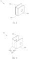
- FIG. 7 is a schematic connection diagram of a first battery, a second battery, and a third busbar component.
- FIG. 8 to FIG. 10 are schematic diagrams of different embodiments of a third busbar component.
- connection may be a fixed connection, or a detachable connection, or an integrated connection, or an electrical connection; or may be a direct connection or an indirect connection implemented through an intermediate medium.
- a battery module in a first embodiment, includes a first battery sequence 1 , a second battery sequence 2 , a first output electrode component 3 , a second output electrode component 4 , a busbar assembly 5 , end plates 7 , and side plates 8 .
- the first battery sequence 1 includes a plurality of first batteries 11 arranged along a longitudinal direction Y of the battery module.
- the second battery sequence 2 includes a plurality of second batteries 21 arranged along the longitudinal direction Y.
- the first battery sequence 1 and the second battery sequence 2 are laid out along a transverse direction X of the battery module that is perpendicular to the longitudinal direction.
- the first batteries 11 and the second batteries 21 may be prismatic lithium-ion batteries.
- the first batteries 11 include two first electrode terminals 111 , that is, a first positive terminal 1111 and a first negative terminal 1112 .
- the second batteries 21 include two second electrode terminals 211 , that is, a second positive terminal 2111 and a second negative terminal 2112 .
- Two end plates 7 and two side plates 8 are interconnected to form a frame.
- the first battery sequence 1 and the second battery sequence 2 are accommodated and fixed in the frame.
- the busbar assembly 5 includes a first busbar component 51 , a second busbar component 52 , and a third busbar component 53 .
- the first busbar component 51 is connected to the first electrode terminal 111 .
- the second busbar component 52 is connected to the second electrode terminal 211 .
- the third busbar component 53 connects the first electrode terminal 111 and the second electrode terminal 211 .
- first busbar components 51 there may be a plurality of first busbar components 51 .
- One first busbar component 51 may connect a first positive terminal 1111 of one first battery 11 and a first negative terminal 1112 of another first battery 11 , thereby serial-connecting the two first batteries 11 together.
- one first busbar component 51 may also connect first positive terminals 1111 of two first batteries 11 , thereby parallel-connecting the two first batteries 11 .
- the plurality of first busbar components 51 serial-connects (and/or parallel-connects) the plurality of first batteries 11 together by connecting to the first electrode terminal 111 .
- second busbar components 52 there may be a plurality of second busbar components 52 .
- the second busbar components 52 serial-connects (and/or parallel-connects) the plurality of second batteries 21 together by connecting to the second electrode terminal 211 .
- the third busbar component 53 connects the first electrode terminal 111 and the second electrode terminal 211 , thereby electrically connecting the first battery sequence 1 and the second battery sequence 2 .
- the first busbar component 51 , the second busbar component 52 , and the third busbar component 53 gather currents of the plurality of first batteries 11 and the plurality of second batteries 21 .
- the first output electrode component 3 is connected to the first electrode terminal 111 of the first battery 11 .
- the second output electrode component 4 is connected to the second electrode terminal 211 of the second battery 21 .
- the first battery 11 connected to the first output electrode component 3 and the second battery 21 connected to the second output electrode component 4 are located at the same end of the battery module along the longitudinal direction Y.
- Polarity of the first electrode terminal 111 connected to the first output electrode component 3 is opposite to polarity of the second electrode terminal 211 connected to the second output electrode component 4 .
- the first output electrode component 3 and the second output electrode component 4 are configured to charge and discharge the battery module.
- this application can not only increase the capacity of the battery module, but also dispose the first output electrode component 3 and the second output electrode component 4 at the same end of the battery module along the longitudinal direction Y to achieve the same-side output of the battery module and simplify the connection structure between battery modules.
- the first output electrode component 3 extends beyond an outer side of the first battery sequence 1 along the longitudinal direction Y so as to conveniently connect to other components (for example, another battery module).
- the second output electrode component 4 extends beyond an outer side of the second battery sequence 2 along the longitudinal direction Y so as to conveniently connect to other components (for example, another battery module).
- the two first electrode terminals 111 are located on the same side of the first battery 11 .
- the two first electrode terminals 111 are both disposed on an upper side of the first battery 11 along a height direction Z.
- the two second electrode terminals 211 are both disposed on an upper side of the second battery 21 along the height direction Z.
- the battery module further includes a harness plate disposed on the upper side of the first battery sequence 1 and the second battery sequence 2 .
- the busbar assembly 5 is fixed onto a lower side of the harness plate.
- the harness plate can collect information (such as voltage and current) of each battery through the first busbar component 51 , the second busbar component 52 , and the third busbar component 53 .
- the battery module further includes a spacer plate 6 disposed between the first battery sequence 1 and the second battery sequence 2 . Two ends of the spacer plate 6 along the longitudinal direction Y are fixed onto the end plates 7 . In a working process of the battery module, both the first battery 11 and the second battery 21 swell. A swelling force may cause a failure of the connection between an end plate 7 and a side plate 8 .
- the spacer plate 6 can improve an anti-swelling capability of the battery module and prevent failure of the battery module.
- the battery module may further include a bottom plate and an upper cover (not shown).
- the top cover is fixed onto an upper side of the harness plate to protect the harness plate and the busbar assembly 5 .
- the bottom plate is disposed on a lower side of the first battery sequence 1 and the second battery sequence 2 and fixed onto the end plates 7 .
- a second embodiment of this application is substantially the same as the first embodiment, but differs in the busbar assembly 5 .
- the first busbar component 51 can connect the first positive terminals 1111 of two (or more) first batteries 11 and the first negative terminals 1112 of two (or more) first batteries 11 concurrently, thereby connecting the four first batteries 11 together in a serial-parallel manner. It is the same with the second busbar component 52 and the third busbar component 53 .
- first batteries 11 connected to the first output electrode component 3 and a plurality of second batteries 21 connected to the second output electrode component 4 .
- a battery module in a third embodiment, includes a first battery sequence 1 , a second battery sequence 2 , a first output electrode component 3 , a second output electrode component 4 , a busbar assembly 5 , end plates 7 (not shown), and side plates 8 (not shown).
- the first battery sequence 1 includes a plurality of first batteries 11 arranged along a longitudinal direction Y of the battery module.
- the second battery sequence 2 includes a plurality of second batteries 21 arranged along the longitudinal direction Y.
- the first battery sequence 1 and the second battery sequence 2 are laid out along a transverse direction X of the battery module that is perpendicular to the longitudinal direction.
- the first batteries 11 include two first electrode terminals 111 , that is, a first positive terminal 1111 and a first negative terminal 1112 .
- the second batteries 21 include two second electrode terminals 211 , that is, a second positive terminal 2111 and a second negative terminal 2112 .
- Two end plates 7 and two side plates 8 are interconnected to form a frame. The first battery sequence 1 and the second battery sequence 2 are accommodated and fixed in the frame.
- the busbar assembly 5 includes a first busbar component 51 , a second busbar component 52 , and a third busbar component 53 .
- the first busbar component 51 is connected to the first electrode terminal 111 .
- the second busbar component 52 is connected to the second electrode terminal 211 .
- the third busbar component 53 connects the first electrode terminal 111 and the second electrode terminal 211 .
- the first output electrode component 3 is connected to the first electrode terminal 111 of the first battery 11 .
- the second output electrode component 4 is connected to the second electrode terminal 211 of the second battery 21 .
- the first battery 11 connected to the first output electrode component 3 and the second battery 21 connected to the second output electrode component 4 are located at the same end of the battery module along the longitudinal direction Y.
- Polarity of the first electrode terminal 111 connected to the first output electrode component 3 is opposite to polarity of the second electrode terminal 211 connected to the second output electrode component 4 .
- the first output electrode component 3 and the second output electrode component 4 are configured to charge and discharge the battery module.
- the first output electrode component 3 extends beyond an outer side of the first battery sequence 1 along the longitudinal direction Y so as to conveniently connect to other external components; and the second output electrode component 4 extends beyond an outer side of the second battery sequence 2 along the longitudinal direction Y so as to conveniently connect to other external components.
- the first electrode terminal 111 of the first battery 11 and the second electrode terminal 211 of the second battery 21 are disposed opposite to each other along the transverse direction X. That is, in the transverse direction X, the two first electrode terminals 11 are both located on a side that is of the first battery 11 and that is close to the second battery 21 , and the two second electrode terminals 211 are both located on a side that is of the second battery 21 and that is close to the first battery 11 .
- the busbar assembly 5 is disposed between the first battery sequence 1 and the second battery sequence 2 . Because the first electrode terminal 111 and the second electrode terminal 211 are disposed opposite to each other along the transverse direction X, the first busbar component 51 and the second busbar component 52 overlap along the transverse direction X, and the first output electrode component 3 and the second output electrode component 4 also overlap along the transverse direction X.
- the battery module further includes a spacer plate 6 disposed between the first battery sequence 1 and the second battery sequence 2 .
- the spacer plate 6 separates the first busbar component 51 from the second busbar component 52 to avoid contact between the first busbar component 51 and the second busbar component 52 and prevent a short circuit.
- the spacer plate 6 also separates the first output electrode component 3 from the second output electrode component 4 to avoid contact between the first output electrode component 3 and the second output electrode component 4 and prevent a short circuit.
- a limiting slot 61 is disposed on the spacer plate 6 .
- the first output electrode component 3 , the second output electrode component 4 , and the busbar assembly 5 are at least partly accommodated in the limiting slot 61 .
- the limiting slot 61 serves a function of fixing a position, and is conducive to assembling the spacer plate 6 , the first output electrode component 3 , the second output electrode component 4 , and the busbar assembly 5 .
- the spacer plate 6 can also support the first output electrode component 3 , the second output electrode component 4 , and the busbar assembly 5 .
- the spacer plate 6 may be an insulated harness plate.
- the harness plate can collect information (such as voltage and current) of each battery through the first busbar component 51 , the second busbar component 52 , and the third busbar component 53 .
- the battery module may further include a bottom plate and an upper cover (not shown).
- the upper cover is disposed on an upper side of the first battery sequence 1 and the second battery sequence 2 and fixed onto the end plates 7 .
- the bottom plate is disposed on a lower side of the first battery sequence 1 and the second battery sequence 2 and fixed onto the end plates 7 .
- the upper cover is generally fixed to the harness plate to protect the harness plate, and therefore, the upper cover generally cannot fix the first battery sequence 1 or the second battery sequence 2 from the upper side.
- the spacer plate 6 is clamped between the first battery sequence 1 and the second battery sequence 2 , and the upper cover does not need to protect the harness plate, and therefore, the upper cover may be directly connected to the end plates 7 and fix the first battery sequence 1 and the second battery sequence 2 from the upper side, so as to improve overall strength of the battery module.
- the third busbar component 53 is generally a bent structure in order to connect the first electrode terminal 111 and the second electrode terminal 211 .
- the third busbar component 53 includes a first part 531 , a second part 532 , and a third part 533 .
- the first part 531 is connected to the first battery 11 .
- the second part 532 is connected to the second battery 21 .
- the third part 533 is bent against the first part 531 and the second part 532 , and the third part 533 connects the first part 531 and the second part 532 .
- the third busbar component 53 is a U-shaped integrated component
- the first part 531 and the second part 532 take on a flat plate shape
- the third part 533 takes on a curved shape.
- the first part 531 and the third part 533 are an L-shaped integrated component, and the third part 533 is connected to the second part 532 .
- the first part 531 may be welded to the first electrode terminal 111 and the second part 532 may be welded to the second electrode terminal 211 first, and then welding is performed along a boundary between the third part 533 and the second part 532 .
- the third part 533 includes a first connecting region 5331 and a second connecting region 5332 .
- the first part 531 and the first connecting region 5331 are an L-shaped integrated component.
- the second part 532 and the second connecting region 5332 are an L-shaped integrated component.
- the first connecting region 5331 is connected to the second connecting region 5332 .
- the spacer plate 6 separates the first part 531 from the second part 532 .
- the third part 533 is located on an outer side of the spacer plate 6 along the longitudinal direction Y.
- the spacer plate 6 can reduce vibration of the first part 531 and the second part 532 along the transverse direction X.
- the first output electrode component 3 is flush with the second output electrode component 4 along a height direction Z, thereby further simplifying a connection structure between two battery modules.
Landscapes
- Chemical & Material Sciences (AREA)
- Chemical Kinetics & Catalysis (AREA)
- Electrochemistry (AREA)
- General Chemical & Material Sciences (AREA)
- Battery Mounting, Suspending (AREA)
- Connection Of Batteries Or Terminals (AREA)
Abstract
Description
-
- 1: First battery sequence;
- 11: First battery;
- 111: First electrode terminal;
- 1111: First positive terminal;
- 1112: First negative terminal;
- 2: Second battery sequence;
- 21: Second battery;
- 211: Second electrode terminal;
- 2111: Second positive terminal;
- 2112: Second negative terminal;
- 3: First output electrode component;
- 4: Second output electrode component;
- 5: Busbar assembly;
- 51: First busbar component;
- 52: Second busbar component;
- 53: Third busbar component;
- 531: First part;
- 532: Second part;
- 533: Third part;
- 5331: First connecting region;
- 5332: Second connecting region;
- 6: Spacer plate;
- 61: Limiting slot;
- 7: End plate;
- 8: Side plate;
- X: Transverse direction;
- Y: Longitudinal direction; and
- Z: Height direction
Claims (20)
Applications Claiming Priority (3)
| Application Number | Priority Date | Filing Date | Title |
|---|---|---|---|
| CN201821509925.9 | 2018-09-14 | ||
| CN201821509925.9U CN208819967U (en) | 2018-09-14 | 2018-09-14 | battery module |
| PCT/CN2019/105370 WO2020052590A1 (en) | 2018-09-14 | 2019-09-11 | Battery module |
Related Parent Applications (1)
| Application Number | Title | Priority Date | Filing Date |
|---|---|---|---|
| PCT/CN2019/105370 Continuation WO2020052590A1 (en) | 2018-09-14 | 2019-09-11 | Battery module |
Publications (2)
| Publication Number | Publication Date |
|---|---|
| US20210111467A1 US20210111467A1 (en) | 2021-04-15 |
| US11799174B2 true US11799174B2 (en) | 2023-10-24 |
Family
ID=66277273
Family Applications (1)
| Application Number | Title | Priority Date | Filing Date |
|---|---|---|---|
| US17/127,585 Active 2041-03-01 US11799174B2 (en) | 2018-09-14 | 2020-12-18 | Battery module |
Country Status (4)
| Country | Link |
|---|---|
| US (1) | US11799174B2 (en) |
| EP (1) | EP3780153B1 (en) |
| CN (1) | CN208819967U (en) |
| WO (1) | WO2020052590A1 (en) |
Families Citing this family (11)
| Publication number | Priority date | Publication date | Assignee | Title |
|---|---|---|---|---|
| CN208819967U (en) | 2018-09-14 | 2019-05-03 | 宁德时代新能源科技股份有限公司 | battery module |
| CN113285149A (en) * | 2020-02-18 | 2021-08-20 | 比亚迪股份有限公司 | Battery, battery module, battery pack and electric vehicle |
| CN113381098A (en) * | 2020-02-21 | 2021-09-10 | 比亚迪股份有限公司 | Battery sequence, battery package and electric motor car |
| CN213752852U (en) * | 2020-11-10 | 2021-07-20 | 江苏塔菲尔动力系统有限公司 | Battery module based on battery is divided into groups and buffer between groups is connected |
| CN114400418A (en) * | 2022-01-26 | 2022-04-26 | 瑞浦能源有限公司 | Battery module and battery pack |
| WO2024031413A1 (en) * | 2022-08-10 | 2024-02-15 | 宁德时代新能源科技股份有限公司 | Battery and electrical device |
| EP4456294A4 (en) * | 2022-08-10 | 2025-05-21 | Contemporary Amperex Technology Co., Limited | Battery, electric device, and forming method for battery |
| WO2024040384A1 (en) * | 2022-08-22 | 2024-02-29 | 宁德时代新能源科技股份有限公司 | Battery cell, battery and electric device |
| WO2024065785A1 (en) * | 2022-09-30 | 2024-04-04 | 宁德时代新能源科技股份有限公司 | Battery and electric device |
| CN115764172A (en) * | 2022-11-23 | 2023-03-07 | 福建时代星云科技有限公司 | Battery module capable of adjusting positions of polar terminals in arrangement mode |
| CN222927716U (en) * | 2024-07-24 | 2025-05-30 | 惠州亿纬锂能股份有限公司 | Connecting piece and battery pack |
Citations (8)
| Publication number | Priority date | Publication date | Assignee | Title |
|---|---|---|---|---|
| CN201682022U (en) | 2010-05-20 | 2010-12-22 | 江苏双登集团有限公司 | Arrangement structure of 12V lead-acid storage battery monomers |
| CN101944582A (en) | 2010-09-10 | 2011-01-12 | 鸥瑞智诺能源科技(北京)有限公司 | Novel stack battery connection method |
| JP2012243597A (en) | 2011-05-20 | 2012-12-10 | Hitachi Vehicle Energy Ltd | Battery pack, and square battery |
| JP2014203747A (en) | 2013-04-08 | 2014-10-27 | 株式会社Gsユアサ | Power storage element module |
| DE102013213527A1 (en) | 2013-07-10 | 2015-01-15 | Robert Bosch Gmbh | Electric cell connector for a battery module |
| US9634445B1 (en) * | 2016-06-15 | 2017-04-25 | Delphi Technologies, Inc. | Electrical bus bar connector system |
| CN208819967U (en) | 2018-09-14 | 2019-05-03 | 宁德时代新能源科技股份有限公司 | battery module |
| EP3817124A1 (en) | 2018-09-10 | 2021-05-05 | Lg Chem, Ltd. | Icb assembly, battery module comprising same, and method for manufacturing same |
-
2018
- 2018-09-14 CN CN201821509925.9U patent/CN208819967U/en active Active
-
2019
- 2019-09-11 WO PCT/CN2019/105370 patent/WO2020052590A1/en not_active Ceased
- 2019-09-11 EP EP19859985.4A patent/EP3780153B1/en active Active
-
2020
- 2020-12-18 US US17/127,585 patent/US11799174B2/en active Active
Patent Citations (10)
| Publication number | Priority date | Publication date | Assignee | Title |
|---|---|---|---|---|
| CN201682022U (en) | 2010-05-20 | 2010-12-22 | 江苏双登集团有限公司 | Arrangement structure of 12V lead-acid storage battery monomers |
| CN101944582A (en) | 2010-09-10 | 2011-01-12 | 鸥瑞智诺能源科技(北京)有限公司 | Novel stack battery connection method |
| JP2012243597A (en) | 2011-05-20 | 2012-12-10 | Hitachi Vehicle Energy Ltd | Battery pack, and square battery |
| JP2014203747A (en) | 2013-04-08 | 2014-10-27 | 株式会社Gsユアサ | Power storage element module |
| DE102013213527A1 (en) | 2013-07-10 | 2015-01-15 | Robert Bosch Gmbh | Electric cell connector for a battery module |
| US20160164063A1 (en) | 2013-07-10 | 2016-06-09 | Robert Bosch Gmbh | Electric cell connector for a battery module |
| US9634445B1 (en) * | 2016-06-15 | 2017-04-25 | Delphi Technologies, Inc. | Electrical bus bar connector system |
| EP3817124A1 (en) | 2018-09-10 | 2021-05-05 | Lg Chem, Ltd. | Icb assembly, battery module comprising same, and method for manufacturing same |
| US20210288385A1 (en) | 2018-09-10 | 2021-09-16 | Lg Chem, Ltd. | ICB Assembly, Battery Module Including Same and Method for Manufacturing Same |
| CN208819967U (en) | 2018-09-14 | 2019-05-03 | 宁德时代新能源科技股份有限公司 | battery module |
Non-Patent Citations (2)
| Title |
|---|
| Contemporary Amperex Technology Co., Limited, Extended European Search Report, EP19859985.4, dated Sep. 27, 2021, 7 pgs. |
| Contemporary Amperex Technology Co., Limited, International Search Report and Written Opinion, PCTCN2019105370, dated Dec. 19, 2019, 14 pgs. |
Also Published As
| Publication number | Publication date |
|---|---|
| EP3780153A4 (en) | 2021-10-27 |
| EP3780153B1 (en) | 2022-09-07 |
| EP3780153A1 (en) | 2021-02-17 |
| CN208819967U (en) | 2019-05-03 |
| WO2020052590A1 (en) | 2020-03-19 |
| US20210111467A1 (en) | 2021-04-15 |
Similar Documents
| Publication | Publication Date | Title |
|---|---|---|
| US11799174B2 (en) | Battery module | |
| KR101815876B1 (en) | Battery pack with apparatus to prevent surge current | |
| JP7048838B2 (en) | Battery module and battery pack with busbar | |
| KR101835582B1 (en) | Battery Pack | |
| KR101016596B1 (en) | Cell cartridge consisting of intercell interconnection | |
| JP4515961B2 (en) | Battery module using secondary battery | |
| US9331324B2 (en) | Connector assembly and battery pack having the same | |
| KR101320393B1 (en) | Battery module | |
| US11990644B2 (en) | Battery pack including connection plate | |
| US7927728B2 (en) | Battery module interface | |
| KR101977454B1 (en) | Battery Pack | |
| KR102317501B1 (en) | Battery pack | |
| EP3496182A1 (en) | Battery pack | |
| KR20160069348A (en) | Secondary battery and battery pack having the same | |
| CN115663406B (en) | Battery cell adapter, battery cell stack and no-module battery pack | |
| KR20200002327U (en) | Spacer for a battery stack and battery module comprising the battery stack | |
| EP3699980B1 (en) | Battery pack | |
| KR102321794B1 (en) | Battery module including connector having bidirectional coupling structure | |
| KR20200129463A (en) | Battery pack | |
| US20240322390A1 (en) | Battery pack | |
| KR102108575B1 (en) | Cell frame structure | |
| CN224204294U (en) | Battery modules and battery packs | |
| KR20250137386A (en) | End plate for batery frame and battery module and battery pack having the same | |
| KR20250010381A (en) | Secondary battery module and manufacturing method thereof |
Legal Events
| Date | Code | Title | Description |
|---|---|---|---|
| FEPP | Fee payment procedure |
Free format text: ENTITY STATUS SET TO UNDISCOUNTED (ORIGINAL EVENT CODE: BIG.); ENTITY STATUS OF PATENT OWNER: LARGE ENTITY |
|
| AS | Assignment |
Owner name: CONTEMPORARY AMPEREX TECHNOLOGY CO., LIMITED, CHINA Free format text: ASSIGNMENT OF ASSIGNORS INTEREST;ASSIGNORS:GAO, HANQING;HU, XIAOWEI;CHEN, CHUANLIAN;AND OTHERS;SIGNING DATES FROM 20201121 TO 20201125;REEL/FRAME:054853/0356 |
|
| STPP | Information on status: patent application and granting procedure in general |
Free format text: APPLICATION DISPATCHED FROM PREEXAM, NOT YET DOCKETED |
|
| STPP | Information on status: patent application and granting procedure in general |
Free format text: DOCKETED NEW CASE - READY FOR EXAMINATION |
|
| STPP | Information on status: patent application and granting procedure in general |
Free format text: NOTICE OF ALLOWANCE MAILED -- APPLICATION RECEIVED IN OFFICE OF PUBLICATIONS |
|
| STPP | Information on status: patent application and granting procedure in general |
Free format text: PUBLICATIONS -- ISSUE FEE PAYMENT RECEIVED |
|
| STPP | Information on status: patent application and granting procedure in general |
Free format text: PUBLICATIONS -- ISSUE FEE PAYMENT VERIFIED |
|
| STCF | Information on status: patent grant |
Free format text: PATENTED CASE |
|
| AS | Assignment |
Owner name: CONTEMPORARY AMPEREX TECHNOLOGY (HONG KONG) LIMITED, CHINA Free format text: ASSIGNMENT OF ASSIGNORS INTEREST;ASSIGNOR:CONTEMPORARY AMPEREX TECHNOLOGY CO., LIMITED;REEL/FRAME:068338/0723 Effective date: 20240806 |