US11796843B2 - Viewing angle control device and display apparatus - Google Patents
Viewing angle control device and display apparatus Download PDFInfo
- Publication number
- US11796843B2 US11796843B2 US16/994,672 US202016994672A US11796843B2 US 11796843 B2 US11796843 B2 US 11796843B2 US 202016994672 A US202016994672 A US 202016994672A US 11796843 B2 US11796843 B2 US 11796843B2
- Authority
- US
- United States
- Prior art keywords
- viewing angle
- control device
- angle control
- polarizing
- portions
- Prior art date
- Legal status (The legal status is an assumption and is not a legal conclusion. Google has not performed a legal analysis and makes no representation as to the accuracy of the status listed.)
- Active, expires
Links
Images


Classifications
-
- G—PHYSICS
- G02—OPTICS
- G02F—OPTICAL DEVICES OR ARRANGEMENTS FOR THE CONTROL OF LIGHT BY MODIFICATION OF THE OPTICAL PROPERTIES OF THE MEDIA OF THE ELEMENTS INVOLVED THEREIN; NON-LINEAR OPTICS; FREQUENCY-CHANGING OF LIGHT; OPTICAL LOGIC ELEMENTS; OPTICAL ANALOGUE/DIGITAL CONVERTERS
- G02F1/00—Devices or arrangements for the control of the intensity, colour, phase, polarisation or direction of light arriving from an independent light source, e.g. switching, gating or modulating; Non-linear optics
- G02F1/01—Devices or arrangements for the control of the intensity, colour, phase, polarisation or direction of light arriving from an independent light source, e.g. switching, gating or modulating; Non-linear optics for the control of the intensity, phase, polarisation or colour
- G02F1/13—Devices or arrangements for the control of the intensity, colour, phase, polarisation or direction of light arriving from an independent light source, e.g. switching, gating or modulating; Non-linear optics for the control of the intensity, phase, polarisation or colour based on liquid crystals, e.g. single liquid crystal display cells
- G02F1/133—Constructional arrangements; Operation of liquid crystal cells; Circuit arrangements
- G02F1/1333—Constructional arrangements; Manufacturing methods
- G02F1/1335—Structural association of cells with optical devices, e.g. polarisers or reflectors
- G02F1/1336—Illuminating devices
- G02F1/13362—Illuminating devices providing polarized light, e.g. by converting a polarisation component into another one
-
- G—PHYSICS
- G02—OPTICS
- G02F—OPTICAL DEVICES OR ARRANGEMENTS FOR THE CONTROL OF LIGHT BY MODIFICATION OF THE OPTICAL PROPERTIES OF THE MEDIA OF THE ELEMENTS INVOLVED THEREIN; NON-LINEAR OPTICS; FREQUENCY-CHANGING OF LIGHT; OPTICAL LOGIC ELEMENTS; OPTICAL ANALOGUE/DIGITAL CONVERTERS
- G02F1/00—Devices or arrangements for the control of the intensity, colour, phase, polarisation or direction of light arriving from an independent light source, e.g. switching, gating or modulating; Non-linear optics
- G02F1/01—Devices or arrangements for the control of the intensity, colour, phase, polarisation or direction of light arriving from an independent light source, e.g. switching, gating or modulating; Non-linear optics for the control of the intensity, phase, polarisation or colour
- G02F1/13—Devices or arrangements for the control of the intensity, colour, phase, polarisation or direction of light arriving from an independent light source, e.g. switching, gating or modulating; Non-linear optics for the control of the intensity, phase, polarisation or colour based on liquid crystals, e.g. single liquid crystal display cells
- G02F1/1323—Arrangements for providing a switchable viewing angle
-
- G—PHYSICS
- G02—OPTICS
- G02F—OPTICAL DEVICES OR ARRANGEMENTS FOR THE CONTROL OF LIGHT BY MODIFICATION OF THE OPTICAL PROPERTIES OF THE MEDIA OF THE ELEMENTS INVOLVED THEREIN; NON-LINEAR OPTICS; FREQUENCY-CHANGING OF LIGHT; OPTICAL LOGIC ELEMENTS; OPTICAL ANALOGUE/DIGITAL CONVERTERS
- G02F1/00—Devices or arrangements for the control of the intensity, colour, phase, polarisation or direction of light arriving from an independent light source, e.g. switching, gating or modulating; Non-linear optics
- G02F1/01—Devices or arrangements for the control of the intensity, colour, phase, polarisation or direction of light arriving from an independent light source, e.g. switching, gating or modulating; Non-linear optics for the control of the intensity, phase, polarisation or colour
- G02F1/13—Devices or arrangements for the control of the intensity, colour, phase, polarisation or direction of light arriving from an independent light source, e.g. switching, gating or modulating; Non-linear optics for the control of the intensity, phase, polarisation or colour based on liquid crystals, e.g. single liquid crystal display cells
- G02F1/133—Constructional arrangements; Operation of liquid crystal cells; Circuit arrangements
- G02F1/1333—Constructional arrangements; Manufacturing methods
- G02F1/1335—Structural association of cells with optical devices, e.g. polarisers or reflectors
- G02F1/133528—Polarisers
-
- G—PHYSICS
- G02—OPTICS
- G02F—OPTICAL DEVICES OR ARRANGEMENTS FOR THE CONTROL OF LIGHT BY MODIFICATION OF THE OPTICAL PROPERTIES OF THE MEDIA OF THE ELEMENTS INVOLVED THEREIN; NON-LINEAR OPTICS; FREQUENCY-CHANGING OF LIGHT; OPTICAL LOGIC ELEMENTS; OPTICAL ANALOGUE/DIGITAL CONVERTERS
- G02F1/00—Devices or arrangements for the control of the intensity, colour, phase, polarisation or direction of light arriving from an independent light source, e.g. switching, gating or modulating; Non-linear optics
- G02F1/01—Devices or arrangements for the control of the intensity, colour, phase, polarisation or direction of light arriving from an independent light source, e.g. switching, gating or modulating; Non-linear optics for the control of the intensity, phase, polarisation or colour
- G02F1/13—Devices or arrangements for the control of the intensity, colour, phase, polarisation or direction of light arriving from an independent light source, e.g. switching, gating or modulating; Non-linear optics for the control of the intensity, phase, polarisation or colour based on liquid crystals, e.g. single liquid crystal display cells
- G02F1/133—Constructional arrangements; Operation of liquid crystal cells; Circuit arrangements
- G02F1/1333—Constructional arrangements; Manufacturing methods
- G02F1/1335—Structural association of cells with optical devices, e.g. polarisers or reflectors
- G02F1/1336—Illuminating devices
- G02F1/133626—Illuminating devices providing two modes of illumination, e.g. day-night
-
- G—PHYSICS
- G09—EDUCATION; CRYPTOGRAPHY; DISPLAY; ADVERTISING; SEALS
- G09F—DISPLAYING; ADVERTISING; SIGNS; LABELS OR NAME-PLATES; SEALS
- G09F9/00—Indicating arrangements for variable information in which the information is built-up on a support by selection or combination of individual elements
- G09F9/30—Indicating arrangements for variable information in which the information is built-up on a support by selection or combination of individual elements in which the desired character or characters are formed by combining individual elements
- G09F9/33—Indicating arrangements for variable information in which the information is built-up on a support by selection or combination of individual elements in which the desired character or characters are formed by combining individual elements being semiconductor devices, e.g. diodes
-
- H—ELECTRICITY
- H10—SEMICONDUCTOR DEVICES; ELECTRIC SOLID-STATE DEVICES NOT OTHERWISE PROVIDED FOR
- H10K—ORGANIC ELECTRIC SOLID-STATE DEVICES
- H10K59/00—Integrated devices, or assemblies of multiple devices, comprising at least one organic light-emitting element covered by group H10K50/00
- H10K59/50—OLEDs integrated with light modulating elements, e.g. with electrochromic elements, photochromic elements or liquid crystal elements
-
- G—PHYSICS
- G02—OPTICS
- G02F—OPTICAL DEVICES OR ARRANGEMENTS FOR THE CONTROL OF LIGHT BY MODIFICATION OF THE OPTICAL PROPERTIES OF THE MEDIA OF THE ELEMENTS INVOLVED THEREIN; NON-LINEAR OPTICS; FREQUENCY-CHANGING OF LIGHT; OPTICAL LOGIC ELEMENTS; OPTICAL ANALOGUE/DIGITAL CONVERTERS
- G02F1/00—Devices or arrangements for the control of the intensity, colour, phase, polarisation or direction of light arriving from an independent light source, e.g. switching, gating or modulating; Non-linear optics
- G02F1/01—Devices or arrangements for the control of the intensity, colour, phase, polarisation or direction of light arriving from an independent light source, e.g. switching, gating or modulating; Non-linear optics for the control of the intensity, phase, polarisation or colour
- G02F1/13—Devices or arrangements for the control of the intensity, colour, phase, polarisation or direction of light arriving from an independent light source, e.g. switching, gating or modulating; Non-linear optics for the control of the intensity, phase, polarisation or colour based on liquid crystals, e.g. single liquid crystal display cells
- G02F1/133—Constructional arrangements; Operation of liquid crystal cells; Circuit arrangements
- G02F1/1333—Constructional arrangements; Manufacturing methods
- G02F1/1335—Structural association of cells with optical devices, e.g. polarisers or reflectors
- G02F1/133528—Polarisers
- G02F1/133538—Polarisers with spatial distribution of the polarisation direction
Definitions
- the disclosure relates to a viewing angle control technique, and particularly relates to a viewing angle control device and a display apparatus.
- a display apparatus is generally provided with a wide viewing angle display effect.
- the wide viewing angle display effect is easy to cause the confidential information to be peeped by others and lead to leakage of the confidential information.
- the general approach is to place a light control film (LCF) in front of the display panel to filter out the light at a large angle.
- the light control film is manually removed from the front of the display panel.
- the disclosure provides a viewing angle control device which has a filter effect at a large viewing angle and has improved light transmittance in the viewing angle direction.
- the disclosure provides a display apparatus having excellent anti-peeping performance.
- an embodiment of the disclosure provides a viewing angle control device.
- the viewing angle control device includes a plurality of first polarizing portions and a plurality of transmissive portions.
- the first polarizing portions are arranged along a first direction and extend in a second direction.
- the transmissive portions and the first polarizing portions are alternately arranged.
- Each of the first polarizing portions has a width in the first direction and a height in a direction perpendicular to the first direction and the second direction, and a ratio of the height to the width of each of the first polarizing portions is greater than 1.
- the display apparatus includes a viewing angle control device and a display panel.
- the viewing angle control device includes a plurality of first polarizing portions and a plurality of transmissive portions.
- the first polarizing portions are arranged along a first direction and extend in a second direction.
- the transmissive portions and the first polarizing portions are alternately arranged.
- Each of the first polarizing portions has a width in the first direction and a height in a direction perpendicular to the first direction and the second direction, and a ratio of the height to the width of each of the first polarizing portions is greater than 1.
- the display panel overlaps the viewing angle control device.
- the display panel is provided with a polarizer on one side facing the viewing angle control device.
- the first polarizing portions have a first transmission axis
- the polarizer has a second transmission axis
- the first transmission axis is perpendicular to the second transmission axis.
- the viewing angle control device through the alternating arrangement of the polarizing portion and the transmissive portion, and an aspect ratio greater than 1 of the polarizing portion, the polarizability of light at a large viewing angle can be increased, and the light energy loss after the light passes through the viewing angle control device can be effectively reduced.
- the display apparatus by configuring the transmission axis of the polarizer provided between the display panel and the viewing angle control device of the above embodiment to be perpendicular to the transmission axis of the polarizing portion of the viewing angle control device, the display apparatus can have a filter effect at a large viewing angle, and the overall brightness of the light at other viewing angles after exiting the display apparatus can be enhanced.
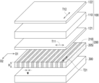
- FIG. 1 is a schematic exploded view showing a display apparatus according to a first embodiment of the disclosure.
- FIG. 2 is a schematic cross-sectional view showing the display apparatus of FIG. 1 .
- FIG. 3 is a schematic exploded view showing a display apparatus according to a second embodiment of the disclosure.
- FIG. 4 is a schematic exploded view showing a display apparatus according to a third embodiment of the disclosure.
- FIG. 5 is a schematic cross-sectional view showing a viewing angle control device according to an embodiment of the disclosure.
- FIG. 6 is a schematic cross-sectional view showing a viewing angle control device according to another embodiment of the disclosure.
- FIG. 7 is a schematic cross-sectional view showing a viewing angle control device according to still another embodiment of the disclosure.
- FIG. 8 is a schematic cross-sectional view showing a viewing angle control device according to still another embodiment of the disclosure.
- FIG. 9 is a schematic exploded view showing a display apparatus according to a fourth embodiment of the disclosure.
- FIG. 10 A to FIG. 10 C are schematic cross-sectional views showing the display apparatus of FIG. 9 in different operation modes.
- FIG. 11 A and FIG. 11 B are schematic cross-sectional views showing a display apparatus according to a fifth embodiment of the disclosure in different operation modes.
- FIG. 12 A and FIG. 12 B are schematic cross-sectional views showing a display apparatus according to a sixth embodiment of the disclosure in different operation modes.
- FIG. 13 A and FIG. 13 B are schematic cross-sectional views showing a display apparatus according to a seventh embodiment of the disclosure in different operation modes.
- the description of “A” component facing “B” component herein may contain the situations that “A” component directly faces “B” component or one or more additional components are between “A” component and “B” component.
- the description of “A” component “adjacent to” “B” component herein may contain the situations that “A” component is directly “adjacent to” “B” component or one or more additional components are between “A” component and “B” component. Accordingly, the drawings and descriptions will be regarded as illustrative in nature and not as restrictive.
- FIG. 1 is a schematic exploded view showing a display apparatus according to a first embodiment of the disclosure.
- FIG. 2 is a cross-sectional view showing the display apparatus of FIG. 1 .
- FIG. 1 omits the illustration of a substrate 201 and a substrate 202 of FIG. 2 .
- a display apparatus 10 includes a display panel 100 and a viewing angle control device 200 .
- the display panel 100 is, for example, a liquid crystal display panel or another suitable non-self-luminous display panel. Therefore, the display apparatus 10 may selectively include a backlight module 300 .
- the display panel 100 overlaps the viewing angle control device 200 .
- the viewing angle control device 200 is located between the display panel 100 and the backlight module 300 .
- the display panel 100 may be located between the viewing angle control device 200 and the backlight module 300 .
- the display panel of the display apparatus may also be an organic light emitting diode (OLED) panel, a micro light emitting diode (micro LED) panel, or another suitable self-luminous display panel. In that case, it is not required to additionally dispose a backlight module, and the viewing angle control device is disposed on the light emitting side of the self-luminous display panel.
- OLED organic light emitting diode
- micro LED micro light emitting diode
- the display panel 100 may include a liquid crystal cell 110 and a first polarizer 121 and a second polarizer 122 located on two opposite sides of the liquid crystal cell 110 .
- the first polarizer 121 is disposed on a side of the display panel 100 facing the viewing angle control device 200 .
- the first polarizer 121 and the second polarizer 122 respectively have a transmission axis T 11 and a transmission axis T 12 , and an axial direction of the transmission axis T 11 of the first polarizer 121 is perpendicular to an axial direction of the transmission axis T 12 of the second polarizer 122 .
- the liquid crystal cell 110 may include a liquid crystal layer (not shown) and two electrode layers (not shown) disposed on two opposite sides of the liquid crystal layer.
- the two electrode layers may respectively have different potentials (e.g., a ground potential and a high potential).
- the potential difference between the two electrode layers may form an electric field in the liquid crystal layer, and the electric field may drive liquid crystal molecules of the liquid crystal layer to rotate to form an arrangement state corresponding to the potential difference.
- the phase retardation of the beam transmitted in the liquid crystal layer can be changed, thereby adjusting the polarization state of this beam.
- the beam B 1 can pass through the second polarizer 122 , so that the pixels of the display panel 100 are in a bright state.
- the pixels of the display panel 100 will be in a dark state.
- the display panel 100 displays a white image as an example.
- the viewing angle control device 200 has a plurality of first polarizing portions 210 and a plurality of transmissive portions 205 .
- the first polarizing portions 210 are arranged along a direction D 1 (for example, arranged on a substrate 201 ) and extend in a direction D 2 .
- the transmissive portions 205 are provided between any two adjacent first polarizing portions 210 , and the transmissive portions 205 exhibit a high transmittance with respect to the beam emitted by the backlight module 300 .
- the first polarizing portions 210 and the transmissive portions 205 are alternately arranged along the direction D 1 .
- the first polarizing portion 210 has a width W in the direction D 1 and a height H in a direction perpendicular to the direction D 1 and the direction D 2 , and a ratio (H/W) of the height H to the width W of the first polarizing portion 210 is greater than 1.
- the ratio of the height H to the width W of the first polarizing portion 210 may be greater than 3. Accordingly, the polarizability of the beam at a large viewing angle can be increased, and the light energy loss of the beam after passing through the viewing angle control device 200 can be effectively reduced.
- the rate of reflection (for example, the reflectivity) of the beam occurring at the interface between the first polarizing portion 210 and the transmissive portion 205 can be reduced, thereby increasing the polarization effect of the viewing angle control device 200 on the beam at the large viewing angle.
- the number and the pitch (i.e., the distribution density) of the plurality of first polarizing portions 210 (or the plurality of transmissive portions 205 ) are only exemplary, and the disclosure is not limited to the content shown in the drawings. In other embodiments, the distribution density of the first polarizing portions 210 may also be adjusted according to the actual design requirements (e.g., the polarizability distribution at different viewing angles).
- the first polarizing portion 210 of the viewing angle control device 200 has a transmission axis T 21 , and an axial direction of the transmission axis T 21 of the first polarizing portion 210 is perpendicular to the axial direction of the transmission axis T 11 of the first polarizer 121 . Therefore, a beam exiting the viewing angle control device 200 at a large angle (e.g., a beam passing obliquely through the first polarizing portion 210 ) cannot pass through the first polarizer 121 of the display panel 100 . Accordingly, the viewing angle range of the display apparatus 10 can be reduced, and namely the anti-peeping effect can be achieved.
- the arrangement direction (i.e., the direction D 1 ) of the plurality of first polarizing portions 210 may be defined as the viewing angle control direction of the display apparatus 10 .
- the beam B 1 may be transmitted to the display panel 100 while still in its original unpolarized state.
- a beam B 2 and a beam B 3 which also come from the backlight module 300 and enter the viewing angle control device 200 at a large angle, lose part of the light energy (e.g., light energy in the direction other than the direction of the first linear polarization P 1 ) after passing through the first polarizing portion 210 and form beams with the first linear polarization P 1 which are transmitted to the display panel 100 .
- the beam B 1 Since the beam B 1 is an unpolarized beam, the beam B 1 can pass through the first polarizer 121 to form a beam with the second linear polarization P 2 .
- the polarization directions of the beam B 2 and the beam B 3 are perpendicular to the transmission axis T 11 of the first polarizer 121 , so the beam B 2 and the beam B 3 are absorbed by the first polarizer 121 and cannot pass through the display panel 100 .
- the display apparatus 10 can achieve a filter effect at a large viewing angle. Namely, the viewing angle range of the display apparatus 10 can be reduced to achieve the purpose of peeping prevention.
- the transmittance (or the polarizability) of the viewing angle control device 200 at a large viewing angle may be determined by the number of the first polarizing portions 210 (i.e., the distribution density of the first polarizing portions 210 ) which the beam needs to pass through.
- the disclosure is not limited thereto, and in other embodiments, the transmittance of the viewing angle control device 200 at a large viewing angle may be further determined by the degree of polarization of the first polarizing portion 210 .
- the distribution density of the first polarizing portions 210 may be increased, so that the beam B 2 originally passes through only one first polarizing portion 210 but now passes through two first polarizing portions 210 . Accordingly, the degree of polarization of the first polarizing portion 210 may be reduced, so as to facilitate the selection of the material of the first polarizing portion 210 .
- the manufacturing method of the viewing angle control device 200 may include forming a plurality of first polarizing portions 210 separate from each other by photolithography on a polarizing layer having a great film thickness (e.g., greater than 10 ⁇ m), and filling a plurality of trenches defined by the first polarizing portions 210 with a gel material having a high light transmittance and curing it to form transmissive portions 205 (it is noted that, the height of the first polarizing portions is less than the thickness of the polarizing layer).
- a great film thickness e.g. 10 ⁇ m
- a light-transmitting material layer and a polarizing material layer may be alternately stacked to form a multi-layer stacked structure, which is then cut along the stacking direction according to the required size to obtain a viewing angle control device 200 .
- the manufacturing method of the viewing angle control device 200 may further selectively include attaching a protective layer on two opposite surfaces of the first polarizing portions 210 and the transmissive portions 205 perpendicular to the arrangement direction to improve the reliability and durability of the viewing angle control device 200 .
- the material of the transmissive portion 205 may include polycarbonate (PC), poly(methyl methacrylate) (PMMA), cyclo-olefin polymer (COP), cyclo-olefin copolymer (COC), polymerized siloxanes, or other materials with high light transmittance.
- the viewing angle control device 200 may selectively have another substrate 202 , and the plurality of first polarizing portions 210 and the plurality of transmissive portions 205 are sandwiched between the substrate 201 and the substrate 202 .
- the materials of the two substrates may include glass, polyethylene terephthalate (PET), polyimide, or other films exhibiting both light transmittance and protection effect.
- FIG. 3 is a schematic exploded view showing a display apparatus according to a second embodiment of the disclosure.
- the difference between a display apparatus 11 of this embodiment and the display apparatus 10 of FIG. 1 lies in the configuration of the polarizing portion.
- a viewing angle control device 200 A further includes a plurality of second polarizing portions 220 , and the second polarizing portions 220 are arranged along the direction D 2 and extend in the direction D 1 .
- the second polarizing portions 220 and the plurality of transmissive portions 205 are alternately arranged along the direction D 2 , and the second polarizing portions 220 intersect with the first polarizing portions 210 (for example, the first polarizing portions 210 and the second polarizing portions 220 are on the same layer, and arranged in a grid pattern).
- each first polarizing portion 210 and each second polarizing portion 220 have an intersection.
- the second polarizing portion 220 has a transmission axis T 22 , and an axial direction of the transmission axis T 22 is parallel to the axial direction of the transmission axis T 21 of the first polarizing portion 210 .
- the axial direction of the transmission axis T 22 of the second polarizing portion 220 is also perpendicular to the axial direction of the transmission axis T 11 of the first polarizer 121 .
- the viewing angle control device 200 A can also provide a filter effect at large angle in the direction D 2
- the display apparatus 11 adopting the viewing angle control device 200 A can also have an anti-peeing function in the direction D 2 to satisfy different product design requirements.
- FIG. 4 is a schematic exploded view showing a display apparatus according to a third embodiment of the disclosure.
- a viewing angle control device 200 B further includes a plurality of second polarizing portions 220 and a plurality of third polarizing portions 230 .
- the second polarizing portions 220 are arranged along a direction D 4 and are respectively connected to the plurality of first polarizing portions 210 and the plurality of third polarizing portions 230 .
- the third polarizing portions 230 are arranged along a direction D 3 and are respectively connected to the plurality of first polarizing portions 210 and the plurality of second polarizing portions 220 . More specifically, the polarizing portions of the viewing angle control device 200 B of this embodiment are arranged in a honeycomb pattern.
- the second polarizing portion 220 has a transmission axis T 22
- the third polarizing portion 230 has a transmission axis T 23
- the axial directions of the transmission axis T 22 and the transmission axis T 23 are parallel to the axial direction of the transmission axis T 21 of the first polarizing portion 210 .
- the axial direction of the transmission axis T 22 of the second polarizing portion 220 and the axial direction of the transmission axis T 23 of the third polarizing portion 230 are also perpendicular to the axial direction of the transmission axis T 11 of the first polarizer 121 .
- the viewing angle control device 200 B can also provide a filter effect at a large angle in the direction D 3 and the direction D 4 .
- the display apparatus 12 adopting the viewing angle control device 200 B can have an anti-peeping function respectively in the direction D 1 , the direction D 3 , and the direction D 4 to satisfy different product design requirements.
- FIG. 5 is a schematic cross-sectional view showing a viewing angle control device according to an embodiment of the disclosure.
- FIG. 6 is a schematic cross-sectional view showing a viewing angle control device according to another embodiment of the disclosure.
- FIG. 7 is a schematic cross-sectional view showing a viewing angle control device according to still another embodiment of the disclosure.
- FIG. 8 is a schematic cross-sectional view showing a viewing angle control device according to still another embodiment of the disclosure.
- the viewing angle control devices shown in FIG. 5 to FIG. 8 are also applicable to the display apparatuses of the foregoing embodiments.
- each first polarizing portion 210 A of the viewing angle control device 200 C has a plurality of polarizing patterns 211 (e.g., a plurality of polarizing patterns 211 separate from each other), and the orthographic projections of the polarizing patterns 211 on a light entrance surface 200 s of the viewing angle control device 200 C overlap each other.
- the polarizing patterns 211 may be flush with each other in the normal direction of the substrate 201 .
- the orthographic projections of the polarizing patterns 211 on the light entrance surface 200 s completely overlap each other, but the disclosure is not limited thereto.
- the manufacturing method of the viewing angle control device 200 C may include alternately forming a material layer containing polarizing patterns 211 and a light-transmitting material layer to form a multi-layer stacked structure on substrate 201 .
- a multi-layer stacked structure of material layers including the polarizing patterns 211 (for example, a height of the material layers is greater than a height of the polarizing patterns) may be formed.
- a light-transmitting material layer may be provided between two polarizing patterns 211 to form a transmissive portion 205 A of the viewing angle control device 200 C.
- the material of the light-transmitting material layer may include polycarbonate (PC), poly(methyl methacrylate) (PMMA), cyclo-olefin polymer (COP), cyclo-olefin copolymer (COC), polymerized siloxanes, or other materials with high light transmittance, but the disclosure is not limited thereto.
- PC polycarbonate
- PMMA poly(methyl methacrylate)
- COP cyclo-olefin polymer
- COC cyclo-olefin copolymer
- siloxanes or other materials with high light transmittance
- the number of the polarizing patterns 211 of the first polarizing portion 210 A is exemplarily described to be four as an example, but it does not mean that the disclosure is limited to the content shown in the drawings. In other embodiments, the number of the polarizing patterns 211 of the first polarizing portion 210 A may also be adjusted according to the actual design requirements (e.g., the aspect ratio of the polarizing portion).
- each polarizing pattern 211 of each first polarizing portion 210 B are staggered with respect to each other in the normal direction of the substrate 201 .
- each polarizing pattern 211 has a symmetry center CS, and a connection line CL connecting the symmetry centers CS of the plurality of polarizing patterns 211 of each first polarizing portion 210 B is oblique with respect to the light entrance surface 200 s .
- the plurality of polarizing patterns 211 of each first polarizing portion 210 B (or transmissive portion 205 B) are arranged obliquely with respect to the normal direction of the substrate 201 .
- a beam B 4 (the transmission path of the beam B 4 is non-parallel to the connection line CL) and a beam B 5 entering the viewing angle control device 200 D pass through the polarizing patterns 211 of the first polarizing portion 210 B on their transmission paths. Therefore, after passing through the viewing angle control device 200 D, the beam B 4 and the beam B 5 can be absorbed by the first polarizer (as shown in FIG. 2 ).
- the transmission path of a beam B 6 (for example, the transmission path of the beam B 6 is parallel to the connection line CL) in the viewing angle control device 200 D does not pass through the polarizing patterns 211 of the first polarizing portion 210 B (namely, the beam B 6 is transmitted in the transmissive portion 205 B), so after exiting the viewing angle control device 200 D, the beam B 6 can pass through the first polarizer of the display panel (as shown in FIG. 2 ).
- the viewing angle range (for example, the center of the viewing angle range) of the display apparatus adopting the viewing angle control device 200 D can deviate from the front viewing direction (namely, the display apparatus can provide an anti-peeping effect within a range covering the front viewing angle and one side viewing angle).
- each first polarizing portion 210 C includes a plurality of polarizing patterns, such as a polarizing pattern 211 , a polarizing pattern 212 , a polarizing pattern 213 , and a polarizing pattern 214 , and the area of an orthographic projection of each polarizing pattern on the light entrance surface 200 s is different from each other.
- an increasing order (from smaller to larger ones) of the widths of the plurality of polarizing patterns of each first polarizing portion 210 C in the direction D 1 is as follows: the polarizing pattern 211 , the polarizing pattern 212 , the polarizing pattern 213 , and the polarizing pattern 214 .
- the areas of the orthographic projections of the plurality of polarizing patterns of the first polarizing portion 210 C on the light entrance surface 200 s gradually increase in a direction away from the light entrance surface 200 s .
- the width of a transmissive portion 205 C in the direction D 1 gradually decreases in a direction from the substrate 201 toward the substrate 202 . Accordingly, different product design requirements (e.g., the viewing angle range of the display apparatus) can be satisfied.
- each first polarizing portion 210 D includes a plurality of polarizing patterns, such as a polarizing pattern 211 , a polarizing pattern 212 , a polarizing pattern 213 , and a polarizing pattern 214 , and the area of an orthographic projection of each polarizing pattern on the light entrance surface 200 s is different from each other.
- an increasing order (from smaller to larger ones) of the widths of the plurality of polarizing patterns of the first polarizing portion 210 D in the direction D 1 is as follows: the polarizing pattern 211 , the polarizing pattern 212 , the polarizing pattern 213 , and the polarizing pattern 214 .
- the areas of the orthographic projections of the plurality of polarizing patterns of the first polarizing portion 210 D on the light entrance surface 200 s gradually decrease in a direction away from the light entrance surface 200 s .
- the width of a transmissive portion 205 D in the direction D 1 gradually increases in a direction from the substrate 201 toward the substrate 202 .
- one side (e.g., the left side) of the plurality of polarizing patterns of the first polarizing portion 210 D is flush with each other in the normal direction of the substrate 201 .
- a beam B 7 entering the viewing angle control device 200 F passes through the polarizing patterns of the first polarizing portion 210 D on its transmission path. Therefore, after passing through the viewing angle control device 200 F, the beam B 7 can be absorbed by the first polarizer (as shown in FIG. 2 ).
- the transmission paths of a beam B 8 and a beam B 9 in the viewing angle control device 200 F do not pass through the polarizing patterns of the first polarizing portion 210 D (namely, the beam B 8 and the beam B 9 are transmitted in the transmissive portion 205 D), so after exiting the viewing angle control device 200 F, the beam B 8 and the beam B 9 can pass through the first polarizer of the display panel (as shown in FIG. 2 ).
- the viewing angle range of the display apparatus adopting the viewing angle control device 200 F can only cover the front viewing angle and one side viewing angle (namely, the display apparatus can have an asymmetric anti-peeping effect at the side viewing angles).
- FIG. 9 is a schematic exploded view showing a display apparatus according to a fourth embodiment of the disclosure.
- FIG. 10 A to FIG. 10 C are schematic cross-sectional views showing the display apparatus of FIG. 9 in different operation modes.
- FIG. 9 omits the illustration of the two substrates 201 and 202 in FIG. 10 A to FIG. 10 C .
- the difference between a display apparatus 20 of this embodiment and the display apparatus 10 of FIG. 1 lies in that the display apparatus 20 further includes an electrically controlled viewing angle switch device 400 .
- the electrically controlled viewing angle switch device 400 overlaps the viewing angle control device 200 and is located between the display panel 100 and the viewing angle control device 200 .
- the electrically controlled viewing angle switch device 400 may be selectively located between the display panel 100 and the backlight module 300 , but the disclosure is not limited thereto.
- the electrically controlled viewing angle switch device 400 includes a liquid crystal layer 420 , a first electrode layer 411 , a second electrode layer 412 , a first substrate 401 , a second substrate 402 , and two alignment films (not shown).
- the liquid crystal layer 420 is sandwiched between the two alignment films.
- the alignment films are used to arrange multiple liquid crystal molecules LC of the liquid crystal layer 420 so that their optical axis is arranged in a predetermined direction.
- the alignment directions of the two alignment films may intersect with each other (for example, non-parallel).
- an included angle between the two alignment directions may range from 90 degrees to 270 degrees.
- the liquid crystal layer 420 may include a twisted nematic liquid crystal (TN-LC).
- the electrically controlled viewing angle switch device 400 of this embodiment may include a twisted nematic liquid crystal cell (TN-LC cell) or a super twisted nematic liquid crystal cell (STN-LC cell).
- the operation mode of the liquid crystal cell of the electrically controlled viewing angle switch device may also be an electrically controlled birefringence (ECB) mode, an optically compensated bend (OCB) mode, an in-plane switching (IPS) mode, or a vertical alignment/multi domain vertical alignment (VA/MVA) mode.
- EBCB electrically controlled birefringence
- OOB optically compensated bend
- IPS in-plane switching
- VA/MVA vertical alignment/multi domain vertical alignment
- the electrode layer of the electrically controlled viewing angle switch device may be at least two electrode layers disposed on two opposite sides of the liquid crystal layer, or at least one electrode layer disposed on one side of the liquid crystal layer.
- first electrode layer 411 of the electrically controlled viewing angle switch device 400 is disposed between the first substrate 401 and the liquid crystal layer 420
- second electrode layer 412 is disposed between the second substrate 402 and the liquid crystal layer 420 .
- the potential difference may form an electric field between the two electrode layers to drive the liquid crystal molecules LC of the liquid crystal layer 420 to rotate.
- the first electrode layer 411 and the second electrode layer 412 are, for example, light-transmissive electrodes
- the material of the light-transmissive electrodes includes indium tin oxide, indium zinc oxide, aluminum tin oxide, aluminum zinc oxide, other suitable oxides, ultrathin metal, metal mesh or wired grid, carbon nanotube, Ag nano-wire, graphene, or a stacked layer of at least two of the above.
- a share mode i.e., a single-side anti-peeping mode, and a double-side anti-peeping mode
- a share mode i.e., a single-side anti-peeping mode, and a double-side anti-peeping mode
- the liquid crystal molecules LC are arranged along the alignment direction of the alignment film.
- the polarization state of the polarized light is changed as the beam passes through the liquid crystal layer 420 (e.g., changing from the direction of the second linear polarization P 2 to the direction of the first linear polarization P 1 , or changing from the direction of the first linear polarization P 1 to the direction of the second linear polarization P 2 ).
- the beam B 2 and the beam B 3 passing through the viewing angle control device 200 respectively have the first linear polarization P 1
- the polarization states of the two beams can be converted from the first linear polarization P 1 to the second linear polarization P 2 , where the polarization direction of the first linear polarization P 1 is perpendicular to the direction of the second linear polarization P 2 . Since the beam B 2 and the beam B 3 entering the display panel 100 have the second linear polarization P 2 , they can pass through the first polarizer 121 of the display panel 100 .
- the beam B 1 is still in the unpolarized state. Therefore, the beam B 1 can also pass through the first polarizer 121 of the display panel 100 after losing part of the light energy.
- the first electrode layer 411 and the second electrode layer 412 of the electrically controlled viewing angle switch device 400 are enabled and have different potentials, and the electric field formed by the potential difference between the two electrode layers can drive the liquid crystal molecules LC of the liquid crystal layer 420 to rotate.
- the liquid crystal layer 420 can generate different phase retardations for the plurality of beams B 1 to B 3 entering at different angles (for example, depending on the included angle between the direction of the transmission path of the beam and the direction of a pre-tilt angle of the alignment film), the beams B 1 to B 3 can respectively have different polarization states after passing through the liquid crystal layer 420 .
- the beam B 1 is still in the unpolarized state, and the beam B 2 and the beam B 3 respectively have the second linear polarization P 2 and the first linear polarization P 1 .
- the display apparatus 20 has a single-side anti-peeping function.
- an absolute value of the voltage difference between the two electrode layers of the electrically controlled viewing angle switch device 400 is greater than 0 V and less than the maximum operating voltage difference of the liquid crystal layer 420 , where the maximum operating voltage is the voltage which drives the average optical axis direction of the liquid crystal layer 420 to be substantially perpendicular to the first substrate 401 (namely, the long axis of most of the liquid crystal molecules LC is perpendicular to the first substrate 401 ).
- phase retardation of the beam B 3 is much smaller than the phase retardation of the beam B 2 .
- the polarization state of the beam B 3 does not change significantly after passing through the electrically controlled viewing angle switch device 400 .
- the phase retardation of the beam B 2 is also greatly reduced.
- the polarization state of the beam B 2 (i.e., the first linear polarization P 1 ) does not change significantly after passing through the electrically controlled viewing angle switch device 400 , either, as shown in FIG. 10 C .
- the beam B 2 and the beam B 3 cannot pass through the display panel 100 .
- the display apparatus 20 has a double-side anti-peeping function, i.e., the double-side anti-peeping mode. Therefore, through the coordination between such an electrically controlled viewing angle switch device 400 having a (super) twisted nematic liquid crystal cell and the viewing angle control device 200 , the functionality of the display apparatus 20 can be increased to satisfy different application scenarios.
- the transmission axis T 11 of the first polarizer 121 is perpendicular to the transmission axis T 21 of the first polarizing portion 210 of the viewing angle control device 200 , but the disclosure is not limited thereto. In other embodiments, the transmission axis of the first polarizer may also be parallel to the transmission axis of the first polarizing portion of the viewing angle control device.
- FIG. 11 A and FIG. 11 B are schematic cross-sectional views showing a display apparatus according to a fifth embodiment of the disclosure in different operation modes.
- the main difference between a display apparatus 21 of this embodiment and the display apparatus 20 of FIG. 10 A lies in that the arrangement of the components is different.
- the display panel 100 is disposed between the backlight module 300 and the electrically controlled viewing angle switch device 400
- a viewing angle control device 200 G is disposed on one side of the electrically controlled viewing angle switch device 400 away from the display panel 100 .
- two operation modes of the display apparatus 21 i.e., a share mode and an anti-peeping mode, will be exemplarily described.
- the liquid crystal molecules LC are arranged along the alignment direction of the alignment film.
- the polarization state of the polarized light is changed as the beam passes through the liquid crystal layer 420 (e.g., changing from the direction of the second linear polarization P 2 to the direction of the first linear polarization P 1 , or changing from the direction of the first linear polarization P 1 to the direction of the second linear polarization P 2 ).
- the plurality of beams exiting the display panel 100 (e.g., the beam B 1 , the beam B 2 , and the beam B 3 ) all have the first linear polarization P 1 .
- the polarization states of the beams can be converted from the first linear polarization P 1 to the second linear polarization P 2 , and the direction of the second linear polarization P 2 is parallel to a transmission axis T 21 A of the first polarizing portion 210 of the viewing angle control device 200 G. Therefore, the beams can all directly pass through the viewing angle control device 200 G to be perceived by the human eye.
- the first electrode layer 411 and the second electrode layer 412 of the electrically controlled viewing angle switch device 400 are enabled and have different potentials, and the electric field formed by the potential difference between the two electrode layers can drive the liquid crystal molecules LC of the liquid crystal layer 420 to rotate.
- the liquid crystal layer 420 can generate different phase retardations for the plurality of beams B 1 to B 3 entering at different angles, the beams B 1 to B 3 respectively have different polarization states after passing through the liquid crystal layer 420 .
- the phase retardation generated by the liquid crystal layer 420 for the beams B 1 to B 3 is smaller, so the polarization states of the beams B 1 to B 3 (i.e., the first linear polarization P 1 ) are not substantially changed. Since the polarization direction of the first linear polarization P 1 is perpendicular to the transmission axis T 21 A of the first polarizing portion 210 , the beam B 2 and the beam B 3 cannot pass through the viewing angle control device 200 G. The beam B 1 does not pass through the first polarizing portion 210 on its transmission path, so the beam B 1 can directly pass through the viewing angle control device 200 G. Accordingly, the display apparatus 21 can provide a double-side anti-peeping function.
- FIG. 12 A and FIG. 12 B are schematic cross-sectional views showing a display apparatus according to a sixth embodiment of the disclosure in different operation modes.
- the main difference between a display apparatus 22 of this embodiment and the display apparatus 21 of FIG. 11 A lies in that the configuration of the polarizing portion of the viewing angle control device is different.
- a first polarizing portion 210 E of a viewing angle control device 200 H has a first surface 210 a and a second surface 210 b which are not covered by the transmissive portion 205 , and the orthographic projections of the first surface 210 a and the second surface 210 b , which are opposite to each other, on the light entrance surface 200 s do not completely overlap each other.
- the side wall of the first polarizing portion 210 E covered by the transmissive portion 205 is oblique with respect to the light entrance surface 200 s .
- the first polarizing portion 210 E is arranged obliquely with respect to the normal direction of the light entrance surface 200 s .
- the viewing angle control device 200 H of this embodiment may be implemented according to the viewing angle control device 200 D of FIG. 6 , and the number of the polarizing patterns 211 of each first polarizing portion 210 B of FIG. 6 may be greater than four.
- two operation modes of the display apparatus 22 i.e., a share mode and an anti-peeping mode, will be exemplarily described.
- the polarization state of the polarized light is changed as the beam passes through the liquid crystal layer 420 (e.g., changing from the direction of the second linear polarization P 2 to the direction of the first linear polarization P 1 , or changing from the direction of the first linear polarization P 1 to the direction of the second linear polarization P 2 ).
- the plurality of beams exiting the display panel 100 e.g., the beam B 1 , the beam B 2 , and the beam B 3 ) all have the first linear polarization P 1 .
- the polarization states of the beams can be converted from the first linear polarization P 1 to the second linear polarization P 2 , and the direction of the second linear polarization P 2 is parallel to the transmission axis T 21 A of the first polarizing portion 210 E of the viewing angle control device 200 H. Therefore, the beams can all directly pass through the viewing angle control device 200 H to be perceived by the human eye.
- the first electrode layer 411 and the second electrode layer 412 of the electrically controlled viewing angle switch device 400 are enabled and have different potentials, and the electric field formed by the potential difference between the two electrode layers can drive the liquid crystal molecules LC of the liquid crystal layer 420 to rotate.
- the liquid crystal layer 420 can generate different phase retardations for the plurality of beams B 1 to B 3 entering at different angles, the beams B 1 to B 3 respectively have different polarization states after passing through the liquid crystal layer 420 .
- the phase retardation generated by the liquid crystal layer 420 for the beams B 1 to B 3 is smaller, so the polarization states of the beams B 1 to B 3 (i.e., the first linear polarization P 1 ) are not changed substantially.
- the display apparatus 22 can provide an anti-peeping function within a range covering the front viewing angle and one side viewing angle, so as to satisfy different application scenarios.
- FIG. 13 A and FIG. 13 B are schematic cross-sectional views showing a display apparatus according to a seventh embodiment of the disclosure in different operation modes.
- the main difference between a display apparatus 30 of this embodiment and the display apparatus 21 of FIG. 11 A lies in that the composition of the display apparatus is different.
- a display panel 100 A of the display apparatus 30 is, for example, an organic light emitting diode (OLED) panel, a micro light emitting diode (micro LED) panel, a mini light emitting diode (mini LED) panel, or another self-luminous display panel.
- OLED organic light emitting diode
- micro LED micro light emitting diode
- mini LED mini light emitting diode
- the display panel 100 A may include a pixel structure layer 130 and a circular polarizer 123 .
- the pixel structure layer 130 may be activated to emit a plurality of beams (e.g., the beam B 1 , the beam B 2 , and the beam B 3 ).
- the beams emitted by the pixel structure layer 130 are circularly polarized light, and after passing through the circular polarizer 123 , the beams have the first linear polarization P 1 and are transmitted to the electrically controlled viewing angle switch device 400 .
- the circular polarizer 123 is composed of, for example, a linear polarizer (not shown) and a quarter wave plate (not shown) and can convert the circularly polarized beam emitted by the pixel structure layer 130 into a linearly polarized state.
- Two operation modes of the display apparatus 30 are similar to those of the display apparatus 21 of FIG. 11 A and FIG. 11 B .
- the display apparatus 30 is operated in the share mode, no potential difference is present between the first electrode layer 411 and the second electrode layer 412 of the electrically controlled viewing angle switch device 400 .
- the electrically controlled viewing angle switch device 400 is disabled, due to the arrangement of the liquid crystal molecules LC, the polarization state of the polarized light is changed as the beam passes through the liquid crystal layer 420 (e.g., changing from the direction of the second linear polarization P 2 to the direction of the first linear polarization P 1 , or changing from the direction of the first linear polarization P 1 to the direction of the second linear polarization P 2 ).
- the plurality of beams exiting the display panel 100 A (e.g., the beam B 1 , the beam B 2 , and the beam B 3 ) all have the first linear polarization P 1 .
- the polarization states of the beams can be converted from the first linear polarization P 1 to the second linear polarization P 2 , and the direction of the second linear polarization P 2 is parallel to the transmission axis T 21 A of the first polarizing portion 210 of the viewing angle control device 200 G. Therefore, the beams can all directly pass through the viewing angle control device 200 G to be perceived by the human eye.
- the first electrode layer 411 and the second electrode layer 412 of the electrically controlled viewing angle switch device 400 are enabled and have different potentials, and the electric field formed by the potential difference between the two electrode layers can drive the liquid crystal molecules LC of the liquid crystal layer 420 to rotate.
- the phase retardation generated by the liquid crystal layer 420 for the beams B 1 to B 3 is smaller, so the polarization states of the beams B 1 to B 3 (i.e., the first linear polarization P 1 ) are not changed substantially.
- the display apparatus 30 can provide a double-side anti-peeping function.
- the viewing angle control device through the alternating arrangement of the polarizing portion and the transmissive portion, and an aspect ratio greater than 1 of the polarizing portion, the polarizability of light at a large viewing angle can be increased, and the light energy loss after the light passes through the viewing angle control device can be effectively reduced.
- the display apparatus by configuring the transmission axis of the polarizer provided between the display panel and the viewing angle control device of the above embodiment to be perpendicular to the transmission axis of the polarizing portion of the viewing angle control device, the display apparatus can have a filter effect at a large viewing angle, and the overall brightness of the light at other viewing angles after exiting the display apparatus can be enhanced.
- the term “the disclosure”, “the disclosure” or the like does not necessarily limit the claim scope to a specific embodiment, and the reference to particularly preferred exemplary embodiments of the disclosure does not imply a limitation on the disclosure, and no such limitation is to be inferred.
- the disclosure is limited only by the spirit and scope of the appended claims. Moreover, these claims may refer to use “first”, “second”, etc. following with noun or element. Such terms should be understood as a nomenclature and should not be construed as giving the limitation on the number of the elements modified by such nomenclature unless specific number has been given.
- the abstract of the disclosure is provided to comply with the rules requiring an abstract, which will allow a searcher to quickly ascertain the subject matter of the technical disclosure of any patent issued from this disclosure.
Abstract
Description
Claims (9)
Priority Applications (1)
| Application Number | Priority Date | Filing Date | Title |
|---|---|---|---|
| US16/994,672 US11796843B2 (en) | 2019-08-19 | 2020-08-17 | Viewing angle control device and display apparatus |
Applications Claiming Priority (4)
| Application Number | Priority Date | Filing Date | Title |
|---|---|---|---|
| US201962889025P | 2019-08-19 | 2019-08-19 | |
| CN202010410754.XA CN112394548B (en) | 2019-08-19 | 2020-05-15 | Viewing angle controller and display device |
| CN202010410754.X | 2020-05-15 | ||
| US16/994,672 US11796843B2 (en) | 2019-08-19 | 2020-08-17 | Viewing angle control device and display apparatus |
Publications (2)
| Publication Number | Publication Date |
|---|---|
| US20210055582A1 US20210055582A1 (en) | 2021-02-25 |
| US11796843B2 true US11796843B2 (en) | 2023-10-24 |
Family
ID=74603820
Family Applications (1)
| Application Number | Title | Priority Date | Filing Date |
|---|---|---|---|
| US16/994,672 Active 2040-09-25 US11796843B2 (en) | 2019-08-19 | 2020-08-17 | Viewing angle control device and display apparatus |
Country Status (3)
| Country | Link |
|---|---|
| US (1) | US11796843B2 (en) |
| CN (1) | CN112394548B (en) |
| TW (1) | TWI768353B (en) |
Families Citing this family (6)
| Publication number | Priority date | Publication date | Assignee | Title |
|---|---|---|---|---|
| TWI724808B (en) * | 2020-03-02 | 2021-04-11 | 友達光電股份有限公司 | Display apparatus |
| CN111812874B (en) * | 2020-07-02 | 2021-07-06 | 深圳市华星光电半导体显示技术有限公司 | Method and device for adjusting dark state visual angle of display panel |
| EP4160302A3 (en) | 2021-09-30 | 2023-04-19 | Shanghai Tianma Micro-Electronics Co., Ltd. | Display module, method for driving the same, display apparatus, and vehicle |
| CN114545692A (en) * | 2022-02-09 | 2022-05-27 | 业成科技(成都)有限公司 | Stacked screen liquid crystal display device |
| CN114815369B (en) * | 2022-04-08 | 2023-06-20 | 中山大学 | Peep-proof display device, peep-proof film and performance test method of peep-proof display device |
| CN115494667B (en) * | 2022-09-05 | 2024-04-12 | 武汉华星光电技术有限公司 | Peep-proof film and display device |
Citations (11)
| Publication number | Priority date | Publication date | Assignee | Title |
|---|---|---|---|---|
| CN1448764A (en) | 2002-04-02 | 2003-10-15 | 精工爱普生株式会社 | LCD, manufacturing method thereof, and electronic device |
| US20040233350A1 (en) * | 2001-04-27 | 2004-11-25 | Hiroyuki Kawanishi | Polarizing plate and liquid crystal display using the same |
| CN1755460A (en) | 2004-09-29 | 2006-04-05 | 株式会社东芝 | Viewing angle control apparatus and display device comprising same |
| US20120169910A1 (en) * | 2010-08-04 | 2012-07-05 | Panasonic Corporation | Image sensor and image capture device |
| US20140110040A1 (en) * | 2012-10-23 | 2014-04-24 | Ronald Steven Cok | Imprinted micro-louver structure method |
| US20150009563A1 (en) * | 2012-03-26 | 2015-01-08 | 3M Innovative Properties Company | Light control film and p-polarization multi-layer film optical film stack |
| CN105572959A (en) | 2016-03-01 | 2016-05-11 | 京东方科技集团股份有限公司 | Liquid crystal display panel and display device |
| CN207301541U (en) | 2016-10-25 | 2018-05-01 | 扬升照明股份有限公司 | Viewing angle control device and viewing angle controllable display device |
| CN108196391A (en) | 2018-01-02 | 2018-06-22 | 京东方科技集团股份有限公司 | A kind of peep-proof device, display device and anti-peeping method |
| TWM563556U (en) | 2017-12-26 | 2018-07-11 | 揚昇照明股份有限公司 | Viewing angle switchable device and viewing angle switchable display module |
| WO2019151334A1 (en) | 2018-01-30 | 2019-08-08 | 富士フイルム株式会社 | Polarization plate, circular polarization plate, and display device |
Family Cites Families (3)
| Publication number | Priority date | Publication date | Assignee | Title |
|---|---|---|---|---|
| JPH09160039A (en) * | 1995-12-04 | 1997-06-20 | Sharp Corp | Liquid crystal display element and its production |
| US6816290B2 (en) * | 2000-07-05 | 2004-11-09 | Sony Corporation | Image display element, and image display device |
| JP4143444B2 (en) * | 2003-03-07 | 2008-09-03 | キヤノン株式会社 | Illumination optics |
-
2020
- 2020-05-15 CN CN202010410754.XA patent/CN112394548B/en active Active
- 2020-05-26 TW TW109117470A patent/TWI768353B/en active
- 2020-08-17 US US16/994,672 patent/US11796843B2/en active Active
Patent Citations (13)
| Publication number | Priority date | Publication date | Assignee | Title |
|---|---|---|---|---|
| US20040233350A1 (en) * | 2001-04-27 | 2004-11-25 | Hiroyuki Kawanishi | Polarizing plate and liquid crystal display using the same |
| CN1448764A (en) | 2002-04-02 | 2003-10-15 | 精工爱普生株式会社 | LCD, manufacturing method thereof, and electronic device |
| US20040004681A1 (en) * | 2002-04-02 | 2004-01-08 | Seiko Epson Corporation | Liquid crystal display device, manufacturing method therefor, and electronic apparatus |
| CN1755460A (en) | 2004-09-29 | 2006-04-05 | 株式会社东芝 | Viewing angle control apparatus and display device comprising same |
| US20120169910A1 (en) * | 2010-08-04 | 2012-07-05 | Panasonic Corporation | Image sensor and image capture device |
| US20150009563A1 (en) * | 2012-03-26 | 2015-01-08 | 3M Innovative Properties Company | Light control film and p-polarization multi-layer film optical film stack |
| US20140110040A1 (en) * | 2012-10-23 | 2014-04-24 | Ronald Steven Cok | Imprinted micro-louver structure method |
| CN105572959A (en) | 2016-03-01 | 2016-05-11 | 京东方科技集团股份有限公司 | Liquid crystal display panel and display device |
| CN207301541U (en) | 2016-10-25 | 2018-05-01 | 扬升照明股份有限公司 | Viewing angle control device and viewing angle controllable display device |
| TWM563556U (en) | 2017-12-26 | 2018-07-11 | 揚昇照明股份有限公司 | Viewing angle switchable device and viewing angle switchable display module |
| CN108196391A (en) | 2018-01-02 | 2018-06-22 | 京东方科技集团股份有限公司 | A kind of peep-proof device, display device and anti-peeping method |
| WO2019151334A1 (en) | 2018-01-30 | 2019-08-08 | 富士フイルム株式会社 | Polarization plate, circular polarization plate, and display device |
| US20200355960A1 (en) * | 2018-01-30 | 2020-11-12 | Fujifilm Corporation | Polarizing plate, circularly polarizing plate, and display device |
Non-Patent Citations (3)
| Title |
|---|
| "Office Action of China Counterpart Application", dated Jun. 17, 2023, p. 1-p. 11. |
| "Office Action of China Counterpart Application", dated Oct. 8, 2022, p. 1-p. 10. |
| "Office Action of Taiwan Counterpart Application", dated May 10, 2021, p. 1-p. 3. |
Also Published As
| Publication number | Publication date |
|---|---|
| TW202122878A (en) | 2021-06-16 |
| CN112394548A (en) | 2021-02-23 |
| CN112394548B (en) | 2024-02-09 |
| TWI768353B (en) | 2022-06-21 |
| US20210055582A1 (en) | 2021-02-25 |
Similar Documents
| Publication | Publication Date | Title |
|---|---|---|
| US11796843B2 (en) | Viewing angle control device and display apparatus | |
| US11526038B2 (en) | Display device, viewing angle limiting device and manufacturing method thereof | |
| US8405806B2 (en) | Liquid crystal display device that includes both a transmissive portion and a reflective portion | |
| CN111796438A (en) | Visual angle switching module and display device | |
| US11221521B2 (en) | Display device | |
| GB2439961A (en) | Liquid crystal cell switchable between two viewing angles | |
| KR20060086174A (en) | Liquid crystal display apparatus | |
| US7336332B2 (en) | Reflective type continuous domain in-plane switching liquid crystal display | |
| JP2009031439A (en) | Liquid crystal display | |
| JP2006293393A (en) | Reflector, method for manufacturing reflector, liquid crystal apparatus, and electronic appliance | |
| TW200410016A (en) | Liquid crystal display device | |
| WO2014084261A1 (en) | Light control film and display device | |
| KR20130039211A (en) | Reflective type liguid crystal display device and method for controlling the same | |
| KR100663074B1 (en) | Reflection and transflection type liquid crystal display device with retardation film | |
| WO2012090839A1 (en) | Liquid-crystal panel and liquid-crystal display | |
| US20050157231A1 (en) | Transflective mode liquid crystal display | |
| US20130271680A1 (en) | Liquid crystal panel, and liquid crystal display | |
| US11340493B2 (en) | Display device | |
| WO2018225631A1 (en) | Liquid crystal display device | |
| KR101971142B1 (en) | Touch panel type liquid crystal display device | |
| US20230288753A1 (en) | Backlight module and display apparatus | |
| WO2017029960A1 (en) | Liquid crystal device and display device | |
| JP7361683B2 (en) | liquid crystal display device | |
| US11714317B2 (en) | Display apparatus | |
| CN219758605U (en) | Multifunctional display panel and multifunctional display device |
Legal Events
| Date | Code | Title | Description |
|---|---|---|---|
| AS | Assignment |
Owner name: CORETRONIC CORPORATION, TAIWAN Free format text: ASSIGNMENT OF ASSIGNORS INTEREST;ASSIGNORS:CHEN, PING-YEN;FANG, CHUNG-YANG;WANG, WEN-CHUN;REEL/FRAME:053507/0303 Effective date: 20200812 |
|
| FEPP | Fee payment procedure |
Free format text: ENTITY STATUS SET TO UNDISCOUNTED (ORIGINAL EVENT CODE: BIG.); ENTITY STATUS OF PATENT OWNER: LARGE ENTITY |
|
| STPP | Information on status: patent application and granting procedure in general |
Free format text: APPLICATION DISPATCHED FROM PREEXAM, NOT YET DOCKETED |
|
| STPP | Information on status: patent application and granting procedure in general |
Free format text: DOCKETED NEW CASE - READY FOR EXAMINATION |
|
| STPP | Information on status: patent application and granting procedure in general |
Free format text: NON FINAL ACTION MAILED |
|
| STPP | Information on status: patent application and granting procedure in general |
Free format text: RESPONSE TO NON-FINAL OFFICE ACTION ENTERED AND FORWARDED TO EXAMINER |
|
| STPP | Information on status: patent application and granting procedure in general |
Free format text: FINAL REJECTION MAILED |
|
| STPP | Information on status: patent application and granting procedure in general |
Free format text: DOCKETED NEW CASE - READY FOR EXAMINATION |
|
| STPP | Information on status: patent application and granting procedure in general |
Free format text: NON FINAL ACTION MAILED |
|
| STPP | Information on status: patent application and granting procedure in general |
Free format text: FINAL REJECTION MAILED |
|
| STPP | Information on status: patent application and granting procedure in general |
Free format text: NOTICE OF ALLOWANCE MAILED -- APPLICATION RECEIVED IN OFFICE OF PUBLICATIONS |
|
| STPP | Information on status: patent application and granting procedure in general |
Free format text: PUBLICATIONS -- ISSUE FEE PAYMENT VERIFIED |
|
| STCF | Information on status: patent grant |
Free format text: PATENTED CASE |