US11784020B2 - Electromagnetic relay - Google Patents
Electromagnetic relay Download PDFInfo
- Publication number
- US11784020B2 US11784020B2 US17/835,876 US202217835876A US11784020B2 US 11784020 B2 US11784020 B2 US 11784020B2 US 202217835876 A US202217835876 A US 202217835876A US 11784020 B2 US11784020 B2 US 11784020B2
- Authority
- US
- United States
- Prior art keywords
- space
- movable contact
- flow path
- disposed
- arc
- Prior art date
- Legal status (The legal status is an assumption and is not a legal conclusion. Google has not performed a legal analysis and makes no representation as to the accuracy of the status listed.)
- Active
Links
Images


Classifications
-
- H—ELECTRICITY
- H01—ELECTRIC ELEMENTS
- H01H—ELECTRIC SWITCHES; RELAYS; SELECTORS; EMERGENCY PROTECTIVE DEVICES
- H01H50/00—Details of electromagnetic relays
- H01H50/54—Contact arrangements
- H01H50/60—Contact arrangements moving contact being rigidly combined with movable part of magnetic circuit
-
- H—ELECTRICITY
- H01—ELECTRIC ELEMENTS
- H01H—ELECTRIC SWITCHES; RELAYS; SELECTORS; EMERGENCY PROTECTIVE DEVICES
- H01H50/00—Details of electromagnetic relays
- H01H50/14—Terminal arrangements
-
- H—ELECTRICITY
- H01—ELECTRIC ELEMENTS
- H01H—ELECTRIC SWITCHES; RELAYS; SELECTORS; EMERGENCY PROTECTIVE DEVICES
- H01H50/00—Details of electromagnetic relays
- H01H50/16—Magnetic circuit arrangements
- H01H50/163—Details concerning air-gaps, e.g. anti-remanence, damping, anti-corrosion
-
- H—ELECTRICITY
- H01—ELECTRIC ELEMENTS
- H01H—ELECTRIC SWITCHES; RELAYS; SELECTORS; EMERGENCY PROTECTIVE DEVICES
- H01H50/00—Details of electromagnetic relays
- H01H50/54—Contact arrangements
-
- H—ELECTRICITY
- H01—ELECTRIC ELEMENTS
- H01H—ELECTRIC SWITCHES; RELAYS; SELECTORS; EMERGENCY PROTECTIVE DEVICES
- H01H50/00—Details of electromagnetic relays
- H01H50/54—Contact arrangements
- H01H50/56—Contact spring sets
- H01H50/58—Driving arrangements structurally associated therewith; Mounting of driving arrangements on armature
-
- H—ELECTRICITY
- H01—ELECTRIC ELEMENTS
- H01H—ELECTRIC SWITCHES; RELAYS; SELECTORS; EMERGENCY PROTECTIVE DEVICES
- H01H9/00—Details of switching devices, not covered by groups H01H1/00 - H01H7/00
- H01H9/30—Means for extinguishing or preventing arc between current-carrying parts
- H01H9/302—Means for extinguishing or preventing arc between current-carrying parts wherein arc-extinguishing gas is evolved from stationary parts
-
- H—ELECTRICITY
- H01—ELECTRIC ELEMENTS
- H01H—ELECTRIC SWITCHES; RELAYS; SELECTORS; EMERGENCY PROTECTIVE DEVICES
- H01H9/00—Details of switching devices, not covered by groups H01H1/00 - H01H7/00
- H01H9/30—Means for extinguishing or preventing arc between current-carrying parts
- H01H9/34—Stationary parts for restricting or subdividing the arc, e.g. barrier plate
-
- H—ELECTRICITY
- H01—ELECTRIC ELEMENTS
- H01H—ELECTRIC SWITCHES; RELAYS; SELECTORS; EMERGENCY PROTECTIVE DEVICES
- H01H2205/00—Movable contacts
- H01H2205/002—Movable contacts fixed to operating part
-
- H—ELECTRICITY
- H01—ELECTRIC ELEMENTS
- H01H—ELECTRIC SWITCHES; RELAYS; SELECTORS; EMERGENCY PROTECTIVE DEVICES
- H01H50/00—Details of electromagnetic relays
- H01H50/02—Bases; Casings; Covers
- H01H50/023—Details concerning sealing, e.g. sealing casing with resin
Definitions
- the present invention relates to an electromagnetic relay.
- an arc occurs at the contacts when the current is cut off. As the arc elevates the temperature of the contacts, the contacts may melt and generate a hot gas containing metal vapor. If the hot gas stays in the vicinity of the contacts, the insulation performance between the contacts is degraded, and the arc may reignite.
- the electromagnetic relay disclosed in Japanese Unexamined Patent Application Publication No. 2016-24864 includes an arc-extinguishing space, a gas inflow space separate from the arc-extinguishing space, and a gas passage, all disposed in a case, for allowing the hot gas to escape from the arc-extinguishing space into the gas inflow space.
- the inlet and outlet of the gas passage are disposed in the vicinity of the contact.
- the hot gas easily returns to the contact through the gas passage.
- the load capacity increases, the amount of hot gas returning to the vicinity of the contact also increases, which may cause the arc to reignite.
- An object of the present invention is to reduce the possibility of re-ignition of an arc at a contact in an electromagnetic relay.
- the electromagnetic relay includes a case, a first fixed terminal, a second fixed terminal, a movable contact piece, a first magnet, a gas flow path, and a partition member.
- the case includes an accommodation space and a side wall covering the accommodation space in a first direction.
- the accommodation space includes a first space and a second space.
- the first fixed terminal includes a first fixed contact disposed in the first space and a first external connecting portion.
- the second fixed terminal is disposed apart from the first fixed terminal.
- the second fixed terminal includes a second fixed contact disposed in the second space and a second external connecting portion protruding from the side wall in the first direction.
- the movable contact piece extends between the first space and the second space.
- the movable contact piece includes a first movable contact facing the first fixed contact and a second movable contact facing the second fixed contact.
- the first magnet configured to extend a first arc generated between the first fixed contact and the first movable contact in the first direction.
- the gas flow path is disposed between the side wall and the movable contact piece.
- the gas flow path includes an inlet communicating with the first space and an outlet communicating with the second space.
- the partition member is disposed between the movable contact piece and the gas flow path, and is configured to partition the first space and the second space from the gas flow path.
- the gas flow path between the side wall and the movable contact piece allows the hot gas due to the first arc to escape from the first space to the second space, decreasing the hot gas due to the first arc that stays in the first space.
- the outlet of the gas flow path communicates with the second space, and thereby the outlet is disposed at a position apart from the first fixed contact.
- the electromagnetic relay may further include a second magnet configured to extend a second arc generated between the second fixed contact and the second movable contact in a second direction opposite to the first direction.
- a second magnet configured to extend a second arc generated between the second fixed contact and the second movable contact in a second direction opposite to the first direction.
- the electromagnetic relay may further include a drive device disposed in the second direction with respect to the first space and the second space.
- the drive device may be configured to move the movable contact piece in moving directions including a direction in which the first movable contact approaches the first fixed contact and a direction in which the first movable contact separates from the first fixed contact.
- the second space may be in communication with a space where the drive unit is installed. In this case, the hot gas due to the second arc can escape to the space where the drive is disposed.
- the first magnet may be further configured to extend the first arc in a direction approaching the first magnet as the first arc is extended in the first direction.
- the case may be disposed between the first magnet and the movable contact piece and may further include an arc contact surface where the first arc contacts.
- the inlet of the gas flow path may face the arc contact surface. In this case, the hot gas due to the first arc can be efficiently guided to the gas flow path.
- the inlet of the gas flow path may include a tapered portion that expands toward the arc contact surface. In this case, the hot gas due to the first arc can be more efficiently guided to the gas flow path.
- the partition member may include a tapered surface inclined toward the arc contact surface in a direction approaching the side wall. In this case, the hot gas due to the first arc can be more efficiently guided to the gas flow path.
- the partition member may further include a convex portion protruding toward the movable contact piece in a second direction opposite to the first direction.
- the convex portion may be disposed farther apart from the arc contact surface than the tapered surface. In this case, the convex portion can limit the hot gas, which has flowed from the first space to the second space through the gas flow path, from returning to the vicinity of the first movable contact.
- the partition member may be a separate body from the side wall of the case.
- the partition member can be made of a material having excellent arc extinguishing performance.
- the electromagnetic relay may further include a flow path member.
- the flow path member may be a separate body from the side wall of the case.
- the flow path member may be disposed between the side wall and the partition member and may constitute the gas flow path.
- the flow path member can be made of a material having excellent arc extinguishing performance.
- FIG. 1 is a perspective view of an electromagnetic relay.
- FIG. 2 is a perspective view of an electromagnetic relay with the cover removed.
- FIG. 3 is a partial cross-sectional view of an electromagnetic relay cut along a plane orthogonal to the up-down direction.
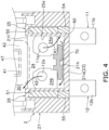
- FIG. 4 is a partial cross-sectional view of an electromagnetic relay cut along a plane orthogonal to the front-back direction.
- FIG. 5 is a cross-sectional perspective view of the periphery of the partition member.
- FIG. 6 is a cross-sectional perspective view of the periphery of the partition member according to a modified example.
- the electromagnetic relay 1 includes a case 2 , a contact device 3 , and a drive device 4 .
- the direction in which the contact device 3 and the drive device 4 are disposed with respect to a later-described base 21 of the case 2 is referred to as up (an example of a second direction), and the opposite direction is referred to as down (an example of a first direction).
- the direction in which the contact device 3 is disposed with respect to the drive device 4 is referred to as front, and the opposite is referred to as back.
- the left-right direction of the paper of FIG. 3 is referred to as left-right.
- these directions are defined only for convenience of description, and do not limit the arrangement directions of the electromagnetic relay 1 .
- the case 2 has a box shape.
- the case 2 made of an insulating material such as resin.
- the case 2 includes a base 21 and a cover 22 .
- the base 21 supports the contact device 3 and the drive device 4 .
- the base 21 includes a bottom 21 a , outer walls 21 b to 21 e , and an inner wall 21 f .
- the bottom 21 a extends in a direction orthogonal to the up-down direction.
- the outer wall 21 b extends upward from the front edge of the bottom 21 a .
- the outer wall 21 c extends upward from the back edge of the bottom 21 a .
- the outer wall 21 d extends upward from the left edge of the bottom 21 a .
- the outer wall 21 e extends upward from the right edge of the bottom 21 a .
- the inner wall 21 f extends upward from the bottom 21 a .
- the inner wall 21 f extends in the left-right direction between the outer wall 21 d and the outer wall 21 e .
- the inner wall 21 f is disposed between the contact device 3 and the drive device 4 in the front-back direction.
- the cover 22 is open downward and is attached to the outer walls 21 b to 21 e of the base 21 so as to cover the bottom 21 a of the base 21 from above.
- the contact device 3 and the drive device 4 are accommodated in the case 2 .
- the contact device 3 includes a first fixed terminal 11 , a second fixed terminal 12 , and a movable contact piece 13 .
- the first fixed terminal 11 and the second fixed terminal 12 may be referred to as fixed terminals 11 and 12 .
- the fixed terminals 11 and 12 are made of a conductive material such as copper.
- the fixed terminals 11 and 12 are plate-shaped terminals and extend in a direction orthogonal to the front-back direction.
- the fixed terminals 11 and 12 are supported by the bottom 21 a of the base 21 .
- the fixed terminals 11 and 12 are fixedly press-fitted to the bottom 21 a of the base 21 .
- the first fixed terminal 11 includes a first fixed contact 11 a and a first external connecting portion 11 b .
- the first fixed contact 11 a is disposed on the front surface of the first fixed terminal 11 .
- the first fixed contact 11 a is fixedly caulked to the first fixed terminal 11 .
- the first fixed contact 11 a may be integrated with the first fixed terminal 11 .
- the first external connecting portion 11 b protrudes downward from the bottom 21 a of the base 21 and is electrically connected to an external device (not shown).
- the second fixed terminal 12 is apart from the first fixed terminal 11 to the left.
- the second fixed terminal 12 has a symmetrical shape with respect to the first fixed terminal 11 .
- the second fixed terminal 12 includes a second fixed contact 12 a and a second external connecting portion 12 b .
- the second fixed contact 12 a is disposed on the front surface of the second fixed terminal 12 .
- the second fixed contact 12 a is fixedly caulked to the second fixed terminal 12 .
- the second fixed contact 12 a may be integrated with the second fixed terminal 12 .
- the second external connecting portion 12 b protrudes downward from the bottom 21 a of the base 21 and is electrically connected to an external device (not shown).
- the movable contact piece 13 is a plate-shaped terminal and is made of a conductive material such as copper.
- the movable contact piece 13 is disposed in front of the fixed terminals 11 and 12 .
- the movable contact piece 13 has a substantially T-shape when viewed from the front-back direction.
- the movable contact piece 13 includes a first movable contact 13 a , a second movable contact 13 b , an up-down extending portion 13 c , and a left-right extending portion 13 d.
- the first movable contact 13 a and the second movable contact 13 b are fixedly caulked to the movable contact piece 13 .
- the first movable contact 13 a and the second movable contact 13 b are disposed on the back surface of the left-right extending portion 13 d .
- the first movable contact 13 a faces the first fixed contact 11 a in the front-back direction.
- the first movable contact 13 a is able to be in contact with the first fixed contact 11 a .
- the second movable contact 13 b is disposed apart from the first movable contact 13 a to the left.
- the second movable contact 13 b faces the second fixed contact 12 a in the front-back direction.
- the second movable contact 13 b is able to be in contact with the second fixed contact 12 a .
- the first movable contact 13 a and the second movable contact 13 b may be integrated with the movable contact piece 13 .
- the up-down extending portion 13 c extends in the up-down direction and is connected to the drive device 4 .
- the left-right extending portion 13 d extends from the lower part of the up-down extending portion 13 c in the left-right direction.
- the drive device 4 is disposed above the contact device 3 .
- the drive device 4 is disposed above a later-described first space 24 a and a later-described second space 24 b .
- the drive device 4 moves the movable contact piece 13 in the direction in which the first movable contact 13 a approaches the first fixed contact 11 a and in the direction in which the first movable contact 13 a separates from the first fixed contact 11 a .
- the drive device 4 moves the movable contact piece 13 in the direction in which the second movable contact 13 b approaches the second fixed contact 12 a and in the direction in which the second movable contact 13 b separates from the second fixed contact 12 a .
- the drive device 4 moves the movable contact piece 13 in the front-back direction.
- the drive device 4 includes a spool 41 , a coil 42 , a yoke 43 , a movable iron piece 44 , a resin member 45 , a return spring 46 , and a fixed iron core 47 .
- the spool 41 is tubular and extends in the front-back direction.
- the coil 42 is wound around the outer circumference of the spool 41 .
- the coil 42 is disposed above the fixed terminals 11 , 12 .
- the yoke 43 has an L-shaped bent shape.
- the yoke 43 includes a coupling portion 43 a and an extending portion 43 b .
- the coupling portion 43 a is disposed behind the spool 41 and is coupled to the fixed iron core 47 .
- the extending portion 43 b extends forward from the upper end of the coupling portion 43 a so as to cover the upper part of the coil 42 .
- the movable iron piece 44 is disposed in front of the fixed iron core 47 .
- the movable iron piece 44 is rotatably supported by the yoke 43 at the front end of the extending portion 43 b .
- the resin member 45 insulates the movable iron piece 44 and the movable contact piece 13 .
- the resin member 45 couples the movable iron piece 44 and the movable contact piece 13 .
- the movable iron piece 44 and the movable contact piece 13 are made by insert-molding into the resin member 45 .
- the resin member 45 and the movable contact piece 13 are rotatable integrally with the movable iron piece 44 in response to the rotation of the movable iron piece 44 .
- the return spring 46 is a coil spring and extends in the front-back direction.
- the return spring 46 has a front end connected to the movable iron piece 44 and a back end connected to a yoke 43 .
- the return spring 46 forces the movable contact piece 13 forward via the movable iron piece 44 and the resin member 45 . That is, the return spring 46 forces the movable contact piece 13 in the direction in which the first movable contact 13 a separates from the first fixed contact 11 a and in the direction in which the second movable contact 13 b separates from the second fixed contact 12 a .
- the fixed iron core 47 is disposed in the spool 41 and penetrates the spool 41 in the front-back direction. The fixed iron core 47 is disposed above the fixed terminals 11 , 12 .
- the operation of the electromagnetic relay 1 will be described. While no voltage is applied to the coil 42 , as shown in FIG. 3 , by the elastic force of the return spring 46 , the first movable contact 13 a is separated from the first fixed contact 11 a and the second movable contact 13 b is separated from the second fixed contact 12 a .
- the electromagnetic force causes the movable iron piece 44 to be attracted to the fixed iron core 47 , which rotates the movable iron piece 44 against the elastic force of the return spring 46 .
- the movable contact piece 13 moves backward, the first movable contact 13 a contacts the first fixed contact 11 a , and the second movable contact 13 b contacts the second fixed contact 12 a .
- the movable iron piece 44 is rotated by the elastic force of the return spring 46 .
- the movable contact piece 13 moves forward, the first movable contact 13 a separates from the first fixed contact 11 a , and the second movable contact 13 b separates from the second fixed contact 12 a.
- the case 2 further includes a side wall 23 , an accommodation space 24 , and magnet housings 25 , 26 .
- the side wall 23 is configured by the bottom 21 a of the base 21 in the present embodiment.
- the side wall 23 covers the accommodation space 24 from below.
- the accommodation space 24 is disposed between the base 21 and the cover 22 .
- the accommodation space 24 is between the magnet housing 25 and the magnet housing 26 in the left-right direction.
- the accommodation space 24 is between the outer wall 21 b and the inner wall 21 f in the front-back direction.
- the first fixed contact 11 a , the second fixed contact 12 a , and the movable contact piece 13 are accommodated in the accommodation space 24 .
- the accommodation space 24 includes a first space 24 a and a second space 24 b .
- the first space 24 a is a space where the first fixed contact 11 a and the first movable contact 13 a are disposed.
- the second space 24 b is a space where the second fixed contact 12 a and the second movable contact 13 b are disposed.
- the second space 24 b is in communication with the first space 24 a .
- the boundary B between the first space 24 a and the second space 24 b is, for example, the center of the movable contact piece 13 in the left-right direction.
- the first space 24 a and the second space 24 b are, at the upper part, in communication with a space 30 where the drive device 4 is disposed.
- the drive device 4 is disposed above the first space 24 a and the second space 24 b in the case 2 .
- the movable contact piece 13 extends between the first space 24 a and the second space 24 b.
- the magnet housing 25 is integrally formed with the base 21 .
- the magnet housing 25 is a concave portion that opens downward, and is formed so as to protrude upward from the side wall 23 .
- the magnet housing 25 is disposed to the right of the first fixed contact 11 a and the first movable contact 13 a .
- the magnet housing 25 includes an arc contact surface 25 a .
- the arc contact surface 25 a is disposed between a later-described magnet 50 and the movable contact piece 13 in the left-right direction.
- the arc contact surface 25 a extends in a direction orthogonal to the left-right direction.
- the arc contact surface 25 a contacts with an arc A 1 (an example of the first arc) generated between the first fixed contact 11 a and the first movable contact 13 a.
- the magnet housing 26 has a symmetrical shape with the magnet housing 25 , and is disposed to the left of the second fixed contact 12 a and the second movable contact 13 b.
- the electromagnetic relay 1 includes magnets 50 and 51 , a gas flow path 60 , and a partition member 70 .
- the magnet 50 is an example of the first magnet.
- the magnet 51 is an example of a second magnet.
- the magnets 50 and 51 are, for example, rectangular permanent magnets.
- the magnet 50 is disposed to the right of the first fixed contact 11 a and the first movable contact 13 a .
- the magnet 50 is housed in the magnet housing 25 .
- the magnet 50 is inserted into the magnet housing 25 from below, and a support member 54 configure to support the magnet 50 from below retains the magnet 50 within the magnet housing 25 .
- the magnet 50 is disposed so that the magnetic flux in the vicinity of the first fixed contact 11 a flows to the right. As shown in FIG. 4 , the magnet 50 extends the arc A 1 downward. Specifically, for example, when a current flows from the first movable contact 13 a toward the first fixed contact 11 a , a downward Lorentz force acts on the arc A 1 , and the arc A 1 is extended downward. As shown in FIG. 4 , as extended downward, the arc A 1 is extended in a direction to approach the arc contact surface 25 a.
- the magnet 51 is disposed to the left of the second fixed contact 12 a and the second movable contact 13 b .
- the magnet 51 is housed in the magnet housing 26 .
- the magnet 51 is inserted into the magnet housing 26 from below, and a support member 55 configure to support the magnet 51 from below retains the magnet 51 within the magnet housing 26 .
- the magnet 51 is disposed so that the magnetic flux in the vicinity of the second fixed contact 12 a flows to the right.
- the magnet 51 is disposed to face the magnet 50 at the different poles each other.
- the magnet 51 extends upward an arc A 2 (an example of the second arc) generated between the second fixed contact 12 a and the second movable contact 13 b .
- an upward Lorentz force acts on the arc A 2 , and the arc A 2 is extended upward.
- the arc A 2 is extended to approach the magnet 51 .
- the gas flow path 60 is disposed in the accommodation space 24 .
- the gas flow path 60 is a path for releasing the hot gas due to the first arc from the first space 24 a to the second space 24 b .
- the gas flow path 60 is disposed below the first space 24 a to the second space 24 b .
- the gas flow path 60 is disposed between the side wall 23 and the movable contact piece 13 in the up-down direction.
- the gas flow path 60 is disposed between the magnet housing 25 and the magnet housing 26 in the left-right direction.
- the gas flow path 60 extends in the left-right direction.
- the gas flow path 60 is configured by the side wall 23 , the partition member 70 , the outer wall 21 b , and the inner wall 21 f.
- the gas flow path 60 includes an inlet 61 and an outlet 62 .
- the inlet 61 is in communication with the first space 24 a .
- the inlet 61 faces the arc contact surface 25 a .
- the inlet 61 includes a tapered portion 61 a that expands toward the arc contact surface 25 a .
- the inlet 61 is closer to the arc contact surface 25 a than the center of the first fixed contact 11 a and the center of the first movable contact 13 a in the left-right direction.
- the outlet 62 is in communication with the second space 24 b .
- the outlet 62 faces the magnet housing 26 .
- the outlet 62 includes a tapered portion 62 a that expands toward the magnet housing 26 .
- the outlet 62 is closer to the magnet housing 26 than the center of the second fixed contact 12 a and the center of the second movable contact 13 b in the left-right direction.
- the partition member 70 is a separate body from the base 21 .
- the partition member 70 is made of, for example, a material having better arc extinguishing performance than that of the base 21 .
- the partition member 70 may be made of the same material as that of the base 21 .
- the partition member 70 is fixed to the base 21 .
- the partition member 70 is disposed in the accommodation space 24 .
- the partition member 70 is disposed between the movable contact piece 13 and the gas flow path 60 .
- the partition member 70 partitions the first space 24 a and the second space 24 b from the gas flow path 60 .
- the partition member 70 extends in the left-right direction and the front-back direction.
- the partition member 70 has, in the front-back direction, side surfaces that are in contact with the outer wall 21 b and the inner wall 21 f .
- the side surfaces of the partition member 70 in the left-right direction are separated from the magnet housings 25 and 26 .
- the lower surface of the partition member 70 is separated from the side wall 23 .
- the partition member 70 includes a concave portion 70 a , convex portions 70 b , 70 c , and tapered surfaces 70 d , 70 e .
- the concave portion 70 a is formed on the lower surface of the partition member 70 .
- the concave portion 70 a is formed at the center of the partition member 70 in the left-right direction.
- the concave portion 70 a is open downward.
- the partition member 70 is supported by support portions 21 g and 21 h that are formed on the base 21 . Specifically, the concave portion 70 a of the partition member 70 is supported by the support portions 21 g and 21 h .
- the support portion 21 g has a shape protruding from the outer wall 21 b toward the accommodation space 24 .
- the support portion 21 g is connected to the side wall 23 .
- the support portion 21 h has a shape protruding from the inner wall 21 f toward the accommodation space 24 .
- the support portion 21 h is connected to the side wall 23 .
- the support portion 21 g is separated from the support portion 21 g in the front-back direction.
- the convex portions 70 b and 70 c are formed on the upper surface of the partition member 70 .
- the convex portions 70 b and 70 c protrude upward toward the movable contact piece 13 .
- the convex portions 70 b and 70 c are disposed farther from the arc contact surface 25 a than the tapered surface 70 d in the left-right direction.
- the convex portion 70 b is disposed in the first space 24 a .
- the convex portion 70 b is disposed to the left of the first fixed contact 11 a and the first movable contact 13 a in the first space 24 a .
- the convex portion 70 c is disposed in the second space 24 b .
- the convex portion 70 c is disposed to the right of the second fixed contact 12 a and the second movable contact 13 b in the second space 24 b.
- the tapered surfaces 70 d and 70 e are formed on the upper surface of the partition member 70 .
- the tapered surface 70 d is disposed below the first fixed contact 11 a and the first movable contact 13 a .
- the tapered surface 70 d is inclined toward the arc contact surface 25 a in a direction approaching the side wall 23 .
- the tapered surface 70 e is disposed below the second fixed contact 12 a and the second movable contact 13 b .
- the tapered surface 70 e is inclined toward the magnet housing 26 in a direction approaching the side wall 23 .
- the gas flow path 60 between the side wall 23 of the case 2 and the movable contact piece 13 allows the hot gas due to the arc A 1 to escape from the first space 24 a to the second space 24 b . Accordingly, the hot gas due to the arc A 1 is hindered from staying in the first space 24 a .
- the hot gas due to the arc A 1 flows from the first space 24 a to the second space 24 b through the gas flow path 60 .
- the outlet 62 of the gas flow path 60 is in communication with the second space 24 b , and thereby the outlet 62 is disposed at a position apart from the first fixed contact 11 a .
- the hot gas which has flowed from the first space 24 a to the second space 24 b through the gas flow path 60 , is unlikely to return to the first space 24 a .
- the possibility of re-ignition of the arc A 1 can be reduced.
- the configurations of the contact device 3 and the drive device 4 may be modified.
- the drive device 4 may have a plunger type structure.
- the configuration of the case 2 may be changed.
- the arrangement and shape of the magnets 50 and 51 may be changed.
- the shape of the partition member 70 may be changed.
- the partition member 70 may have any shape that partitions the first space 24 a and the second space 24 b from the gas flow path 60 .
- at least one of the convex portions 70 b and 70 c may be omitted, or a convex portion may be formed at the boundary B between the first space 24 a and the second space 24 b.
- FIG. 6 is a cross-sectional perspective view of the periphery of the partition member 70 according to a modified example.
- the electromagnetic relay 1 may further include a flow path member 80 .
- the flow path member 80 is a separate body from the case 2 .
- the flow path member 80 is disposed between the side wall 23 and the partition member 70 .
- the gas flow path 60 is configured by the flow path member 80 , the partition member 70 , the outer wall 21 b , and the inner wall 21 f .
- the flow path member 80 is fixed to the side wall 23 .
- the flow path member 80 may be made of, for example, a material having better arc extinguishing performance than that of the base 21 .
- the partition member 70 and the flow path member 80 may be integrated together.
Abstract
Description
-
- 1 Electromagnetic relay
- 2 Case
- 4 Drive device
- 11 First fixed terminal
- 12 Second fixed terminal
- 12 a Second fixed contact
- 13 Movable contact piece
- 13 a First movable contact
- 13 b Second movable contact
- 23 Side wall
- 24 Accommodation space
- 24 a First space
- 24 b Second space
- 25 a Arc contact surface
- 50 Magnet (one example of first magnet)
- 51 Magnet (one example of second magnet)
- 60 Gas flow path
- 61 a Tapered portion
- 70 Partition member
- 70 d Tapered surface
Claims (10)
Applications Claiming Priority (2)
| Application Number | Priority Date | Filing Date | Title |
|---|---|---|---|
| JP2021106421A JP2023004605A (en) | 2021-06-28 | 2021-06-28 | electromagnetic relay |
| JP2021-106421 | 2021-06-28 |
Publications (2)
| Publication Number | Publication Date |
|---|---|
| US20220415599A1 US20220415599A1 (en) | 2022-12-29 |
| US11784020B2 true US11784020B2 (en) | 2023-10-10 |
Family
ID=84388201
Family Applications (1)
| Application Number | Title | Priority Date | Filing Date |
|---|---|---|---|
| US17/835,876 Active US11784020B2 (en) | 2021-06-28 | 2022-06-08 | Electromagnetic relay |
Country Status (4)
| Country | Link |
|---|---|
| US (1) | US11784020B2 (en) |
| JP (1) | JP2023004605A (en) |
| CN (1) | CN115602495A (en) |
| DE (1) | DE102022113942A1 (en) |
Citations (10)
| Publication number | Priority date | Publication date | Assignee | Title |
|---|---|---|---|---|
| US4421959A (en) * | 1982-04-19 | 1983-12-20 | Eaton Corporation | Bridging contactor with main and arcing contacts |
| US5546061A (en) * | 1994-02-22 | 1996-08-13 | Nippondenso Co., Ltd. | Plunger type electromagnetic relay with arc extinguishing structure |
| US6700466B1 (en) * | 1999-10-14 | 2004-03-02 | Matsushita Electric Works, Ltd. | Contactor |
| US6975194B2 (en) * | 2002-08-09 | 2005-12-13 | Omron Corporation | Switching device |
| US20100060394A1 (en) * | 2008-09-05 | 2010-03-11 | Anden Co., Ltd. | Electromagnetic relay |
| US20120313737A1 (en) * | 2011-06-07 | 2012-12-13 | Fujitsu Component Limited | Electromagnetic relay and method of manufacturing the same |
| US8519811B2 (en) * | 2010-03-30 | 2013-08-27 | Anden Co., Ltd. | Electromagnetic relay |
| JP2016024864A (en) | 2014-07-16 | 2016-02-08 | 富士電機機器制御株式会社 | Contact mechanism and electromagnetic contactor employing the same |
| US20180182584A1 (en) * | 2016-12-27 | 2018-06-28 | Fujitsu Component Limited | Electromagnetic relay |
| US20190035585A1 (en) * | 2016-04-22 | 2019-01-31 | Omron Corporation | Electromagnetic relay |
-
2021
- 2021-06-28 JP JP2021106421A patent/JP2023004605A/en active Pending
-
2022
- 2022-06-02 DE DE102022113942.5A patent/DE102022113942A1/en active Pending
- 2022-06-06 CN CN202210632933.7A patent/CN115602495A/en active Pending
- 2022-06-08 US US17/835,876 patent/US11784020B2/en active Active
Patent Citations (10)
| Publication number | Priority date | Publication date | Assignee | Title |
|---|---|---|---|---|
| US4421959A (en) * | 1982-04-19 | 1983-12-20 | Eaton Corporation | Bridging contactor with main and arcing contacts |
| US5546061A (en) * | 1994-02-22 | 1996-08-13 | Nippondenso Co., Ltd. | Plunger type electromagnetic relay with arc extinguishing structure |
| US6700466B1 (en) * | 1999-10-14 | 2004-03-02 | Matsushita Electric Works, Ltd. | Contactor |
| US6975194B2 (en) * | 2002-08-09 | 2005-12-13 | Omron Corporation | Switching device |
| US20100060394A1 (en) * | 2008-09-05 | 2010-03-11 | Anden Co., Ltd. | Electromagnetic relay |
| US8519811B2 (en) * | 2010-03-30 | 2013-08-27 | Anden Co., Ltd. | Electromagnetic relay |
| US20120313737A1 (en) * | 2011-06-07 | 2012-12-13 | Fujitsu Component Limited | Electromagnetic relay and method of manufacturing the same |
| JP2016024864A (en) | 2014-07-16 | 2016-02-08 | 富士電機機器制御株式会社 | Contact mechanism and electromagnetic contactor employing the same |
| US20190035585A1 (en) * | 2016-04-22 | 2019-01-31 | Omron Corporation | Electromagnetic relay |
| US20180182584A1 (en) * | 2016-12-27 | 2018-06-28 | Fujitsu Component Limited | Electromagnetic relay |
Also Published As
| Publication number | Publication date |
|---|---|
| US20220415599A1 (en) | 2022-12-29 |
| JP2023004605A (en) | 2023-01-17 |
| CN115602495A (en) | 2023-01-13 |
| DE102022113942A1 (en) | 2022-12-29 |
Similar Documents
| Publication | Publication Date | Title |
|---|---|---|
| EP3139396B1 (en) | Contact switching device | |
| CN110323105B (en) | Relay with a movable contact | |
| US20220293375A1 (en) | Electromagnetic relay | |
| JP2017068926A (en) | Electromagnetic relay | |
| US20220293378A1 (en) | Electromagnetic relay | |
| US11621136B2 (en) | Relay | |
| US20230019139A1 (en) | Relay | |
| JP7390560B2 (en) | Electromagnetic relays and insulation materials for electromagnetic relays | |
| US20220165527A1 (en) | Electromagnetic relay | |
| US11387063B2 (en) | Contact point device and electromagnetic relay | |
| US11784020B2 (en) | Electromagnetic relay | |
| US20220293374A1 (en) | Electromagnetic relay | |
| US20220406546A1 (en) | Electromagnetic relay | |
| US11705292B2 (en) | Electromagnetic relay | |
| US11908650B2 (en) | Electromagnetic relay | |
| JP7357193B2 (en) | electromagnetic relay | |
| US20240136133A1 (en) | Electromagnetic relay | |
| JP2020173939A (en) | Magnetic relay | |
| EP4276877A1 (en) | Electromagnetic relay | |
| TW201419357A (en) | Switch | |
| WO2023053686A1 (en) | Electromagnetic relay | |
| CN117981034A (en) | Electromagnetic relay | |
| JP2023051498A (en) | electromagnetic relay | |
| JP2023051497A (en) | electromagnetic relay | |
| JP2021083160A (en) | Electric connection device |
Legal Events
| Date | Code | Title | Description |
|---|---|---|---|
| AS | Assignment |
Owner name: OMRON CORPORATION, JAPAN Free format text: ASSIGNMENT OF ASSIGNORS INTEREST;ASSIGNORS:KAWAGUCHI, NAOKI;NISHIDA, TAKESHI;FURUKAWA, KAZUKI;AND OTHERS;SIGNING DATES FROM 20220518 TO 20220527;REEL/FRAME:060143/0118 |
|
| FEPP | Fee payment procedure |
Free format text: ENTITY STATUS SET TO UNDISCOUNTED (ORIGINAL EVENT CODE: BIG.); ENTITY STATUS OF PATENT OWNER: LARGE ENTITY |
|
| STPP | Information on status: patent application and granting procedure in general |
Free format text: DOCKETED NEW CASE - READY FOR EXAMINATION |
|
| STPP | Information on status: patent application and granting procedure in general |
Free format text: NON FINAL ACTION MAILED |
|
| STPP | Information on status: patent application and granting procedure in general |
Free format text: NOTICE OF ALLOWANCE MAILED -- APPLICATION RECEIVED IN OFFICE OF PUBLICATIONS |
|
| STPP | Information on status: patent application and granting procedure in general |
Free format text: PUBLICATIONS -- ISSUE FEE PAYMENT RECEIVED |
|
| STPP | Information on status: patent application and granting procedure in general |
Free format text: PUBLICATIONS -- ISSUE FEE PAYMENT VERIFIED |
|
| STCF | Information on status: patent grant |
Free format text: PATENTED CASE |