US11782874B2 - Bottom-up pre-emptive cache update in a multi-level redundant cache system - Google Patents
Bottom-up pre-emptive cache update in a multi-level redundant cache system Download PDFInfo
- Publication number
- US11782874B2 US11782874B2 US17/383,846 US202117383846A US11782874B2 US 11782874 B2 US11782874 B2 US 11782874B2 US 202117383846 A US202117383846 A US 202117383846A US 11782874 B2 US11782874 B2 US 11782874B2
- Authority
- US
- United States
- Prior art keywords
- ledger
- data
- client
- dataset
- cache
- Prior art date
- Legal status (The legal status is an assumption and is not a legal conclusion. Google has not performed a legal analysis and makes no representation as to the accuracy of the status listed.)
- Active, expires
Links
Images


Classifications
-
- G—PHYSICS
- G06—COMPUTING OR CALCULATING; COUNTING
- G06F—ELECTRIC DIGITAL DATA PROCESSING
- G06F12/00—Accessing, addressing or allocating within memory systems or architectures
- G06F12/02—Addressing or allocation; Relocation
- G06F12/08—Addressing or allocation; Relocation in hierarchically structured memory systems, e.g. virtual memory systems
- G06F12/0802—Addressing of a memory level in which the access to the desired data or data block requires associative addressing means, e.g. caches
- G06F12/0893—Caches characterised by their organisation or structure
- G06F12/0897—Caches characterised by their organisation or structure with two or more cache hierarchy levels
-
- G—PHYSICS
- G06—COMPUTING OR CALCULATING; COUNTING
- G06F—ELECTRIC DIGITAL DATA PROCESSING
- G06F16/00—Information retrieval; Database structures therefor; File system structures therefor
- G06F16/10—File systems; File servers
- G06F16/11—File system administration, e.g. details of archiving or snapshots
- G06F16/119—Details of migration of file systems
-
- G—PHYSICS
- G06—COMPUTING OR CALCULATING; COUNTING
- G06F—ELECTRIC DIGITAL DATA PROCESSING
- G06F12/00—Accessing, addressing or allocating within memory systems or architectures
- G06F12/02—Addressing or allocation; Relocation
- G06F12/08—Addressing or allocation; Relocation in hierarchically structured memory systems, e.g. virtual memory systems
- G06F12/0802—Addressing of a memory level in which the access to the desired data or data block requires associative addressing means, e.g. caches
- G06F12/0806—Multiuser, multiprocessor or multiprocessing cache systems
- G06F12/0811—Multiuser, multiprocessor or multiprocessing cache systems with multilevel cache hierarchies
-
- G—PHYSICS
- G06—COMPUTING OR CALCULATING; COUNTING
- G06F—ELECTRIC DIGITAL DATA PROCESSING
- G06F12/00—Accessing, addressing or allocating within memory systems or architectures
- G06F12/02—Addressing or allocation; Relocation
- G06F12/08—Addressing or allocation; Relocation in hierarchically structured memory systems, e.g. virtual memory systems
- G06F12/0802—Addressing of a memory level in which the access to the desired data or data block requires associative addressing means, e.g. caches
- G06F12/0891—Addressing of a memory level in which the access to the desired data or data block requires associative addressing means, e.g. caches using clearing, invalidating or resetting means
-
- G—PHYSICS
- G06—COMPUTING OR CALCULATING; COUNTING
- G06F—ELECTRIC DIGITAL DATA PROCESSING
- G06F16/00—Information retrieval; Database structures therefor; File system structures therefor
- G06F16/10—File systems; File servers
- G06F16/18—File system types
- G06F16/182—Distributed file systems
- G06F16/1824—Distributed file systems implemented using Network-attached Storage [NAS] architecture
-
- G—PHYSICS
- G06—COMPUTING OR CALCULATING; COUNTING
- G06F—ELECTRIC DIGITAL DATA PROCESSING
- G06F9/00—Arrangements for program control, e.g. control units
- G06F9/06—Arrangements for program control, e.g. control units using stored programs, i.e. using an internal store of processing equipment to receive or retain programs
- G06F9/44—Arrangements for executing specific programs
- G06F9/455—Emulation; Interpretation; Software simulation, e.g. virtualisation or emulation of application or operating system execution engines
-
- G—PHYSICS
- G06—COMPUTING OR CALCULATING; COUNTING
- G06F—ELECTRIC DIGITAL DATA PROCESSING
- G06F12/00—Accessing, addressing or allocating within memory systems or architectures
- G06F12/02—Addressing or allocation; Relocation
- G06F12/08—Addressing or allocation; Relocation in hierarchically structured memory systems, e.g. virtual memory systems
- G06F12/0802—Addressing of a memory level in which the access to the desired data or data block requires associative addressing means, e.g. caches
- G06F12/0862—Addressing of a memory level in which the access to the desired data or data block requires associative addressing means, e.g. caches with prefetch
Definitions
- Embodiments are generally directed to cache memory systems, and more specifically to bottom-up pre-emptive updating of caches in a multi-cache system.
- VMs virtual machines
- All caching imposes a cost involved in keeping the cache coherent and up-to-date with a backend system so that it can return accurate referral information to clients using the redirection service.
- Such a multi-level cache system significantly reduces the time taken to service the request, thus enhancing performance.
- FIG. 1 is a diagram of a distributed storage cluster system implementing a bottom-up pre-emptive cache update process, under some embodiments.
- FIG. 2 illustrates a hierarchy of caches in a multi-level cache system that implements a bottom-up cache update process, under some embodiments.
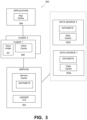
- FIG. 3 is a block diagram of a hierarchical multi-node system using a bottom-up pre-emptive cache process, under some embodiments.
- FIG. 4 is a flowchart that illustrates a method of performing bottom-up pre-emptive cache updates, under some embodiments.
- FIG. 5 is a block diagram illustrating implementing a cache update process in an example namespace redirection service application, under some embodiments.
- FIGS. 6 A to 6 C provide a time sequence diagram illustrating cache and ledger entries during the lookup and cache updates for the dataset migration example of FIG. 5 , with FIG. 6 A illustrating a first point in time, T 1 , FIG. 6 B illustrating a second point in time, T 2 , and FIG. 6 C illustrating a third point in time, T 3 .
- FIG. 7 is a diagram that summarizes the ledger number update process for the examples of FIGS. 6 A to 6 C , under an example embodiment.
- FIG. 8 is a block diagram of a computer system used to execute one or more software components of a system implementing a bottom-up pre-emptive cache update process, under some embodiments.
- a computer-usable medium or computer-readable medium may be any physical medium that can contain or store the program for use by or in connection with the instruction execution system, apparatus or device.
- the computer-readable storage medium or computer-usable medium may be, but is not limited to, a random-access memory (RAM), read-only memory (ROM), or a persistent store, such as a mass storage device, hard drives, CDROM, DVDROM, tape, erasable programmable read-only memory (EPROM or flash memory), or any magnetic, electromagnetic, optical, or electrical means or system, apparatus or device for storing information.
- RAM random-access memory
- ROM read-only memory
- EPROM or flash memory erasable programmable read-only memory
- the computer-readable storage medium or computer-usable medium may be any combination of these devices or even paper or another suitable medium upon which the program code is printed, as the program code can be electronically captured, via, for instance, optical scanning of the paper or other medium, then compiled, interpreted, or otherwise processed in a suitable manner, if necessary, and then stored in a computer memory.
- Applications software programs or computer-readable instructions may be referred to as components or modules.
- Applications may be hardwired or hard coded in hardware or take the form of software executing on a general-purpose computer or be hardwired or hard coded in hardware such that when the software is loaded into and/or executed by the computer, the computer becomes an apparatus for practicing the invention.
- Applications may also be downloaded, in whole or in part, through the use of a software development kit or toolkit that enables the creation and implementation of the described embodiments.
- these implementations, or any other form that the invention may take may be referred to as techniques. In general, the order of the steps of disclosed processes may be altered within the scope of the invention.
- Some embodiments of the invention involve automated backup and data storage techniques in a distributed system, such as a very large-scale wide area network (WAN), metropolitan area network (MAN), or cloud based network system, however, those skilled in the art will appreciate that embodiments are not limited thereto, and may include smaller-scale networks, such as LANs (local area networks).
- WAN wide area network
- MAN metropolitan area network
- cloud based network system a system that provides a wide area network
- LANs local area networks
- aspects of the one or more embodiments described herein may be implemented on one or more computers executing software instructions, and the computers may be networked in a client-server arrangement or similar distributed computer network.
- FIG. 1 is a diagram of a distributed storage cluster system implementing a bottom-up pre-emptive cache update process, under some embodiments.
- a network server computer 102 is coupled directly or indirectly to the network clients and/or servers 104 and 106 through network 110 , which may be a cloud network, LAN, WAN or other appropriate network.
- Network 110 provides connectivity to the various systems, components, and resources of system 100 , and may be implemented using protocols such as Transmission Control Protocol (TCP) and/or Internet Protocol (IP), well known in the relevant arts.
- TCP Transmission Control Protocol
- IP Internet Protocol
- network 110 may represent a cloud-based network environment in which applications, servers and data are maintained and provided through a centralized cloud-computing platform.
- the data sourced by system 100 may be stored in any number of other storage locations and devices, such as local client storage, server storage, or network storage (e.g., 114 ), which may at least be partially implemented through storage device arrays, such as RAID components.
- Embodiments can be used in a physical storage environment, a virtual storage environment, or a mix of both, running a deduplicated backup program.
- system 100 includes a number of virtual machines (VMs) or groups of VMs that are provided to serve as backup targets.
- VMs virtual machines
- Such target VMs may be organized into one or more vCenters (virtual centers) representing a physical or virtual network of many virtual machines (VMs), such as on the order of thousands of VMs each.
- the VMs serve as target storage devices for data backed up from one or more data sources, such as file system (FS) clients.
- Other data sources having data to be protected and backed up may include other VMs 104 and data in network storage 114 .
- the data sourced by the data source may be any appropriate type of data, such as database data that is part of a database management system. In this case, the data may reside on one or more storage devices of the system, and may be stored in the database in a variety of formats.
- network system 100 includes a server 102 that functions as a backup server by executing a backup management process 112 that automates the backup of network data using the target VM devices or the network storage devices 114 .
- the backup process 112 uses certain known full and incremental (or differencing) backup techniques along with a snapshot backup process that is used to store an image or images of the system(s) to be backed up prior to the full or incremental backup operations.
- the network system of FIG. 1 may be implemented as a DellEMC PowerProtect Data Manager (or similar) data protection system.
- This is an enterprise-level data protection software platform that automates data backups to tape, disk, and flash-based storage media across physical and virtual environments.
- a number of different operating systems e.g., Windows, MacOS, Linux, etc.
- Deduplication of backup data is provided by integration with systems such as DellEMC Data Domain and other similar storage solutions.
- server 102 may be implemented as a Data Domain Restorer (DDR) Deduplication Storage: server provided by DellEMC Corporation.
- DDR Data Domain Restorer
- a number of different users may use backup management process 112 to back up their data on a regular basis to virtual or physical storage media for purposes of data protection.
- the saved datasets can then be used in data restore operations to restore any data that may be lost or compromised due to system failure or attack.
- data centers 104 and 106 may represent different DDR sites that function as sources and/or targets for data.
- a system such as shown in FIG. 1 may have many different caches used by the various network elements, such as the server or servers 102 , the client data centers 104 , 106 , and any application or service 108 that may be executing on the system.
- these multiple components all process the same data and cache it using their respective caches.
- the data may change, get old, be relocated (e.g., through namespace redirection process 118 ), or be subject to a configuration change to the network itself. Any such change can cause the data in one or more of the caches to become outdated (stale).
- the caches for processes closest to the data have the newest data and caches for higher levels may contain stale data when the lower level caches update. It is important that the caches be notified of any stale data so that cache update processes can be used to prevent cache misses, which often impose excessive processing overhead.
- the system of FIG. 1 includes a cache update process 120 that provides a bottom-up pre-emptive cache update in the system 100 , which has potentially several levels of multi-level caches.
- FIG. 2 illustrates a hierarchy of caches in a multi-level cache system that implements a bottom-up cache update process, under some embodiments.
- the example of FIG. 2 shows four caches of different levels denoted cache level A, 208 , cache level B, 208 , cache level C, 208 , and cache level D, 202 .
- cache level D is the lowest level cache in that it is used in or most closely associated with the VM of the actual data source, in this case a database.
- the next level cache, level C is a next higher level cache, in this case a service (such as the namespace redirection service 118 ); cache level B is then the next higher level cache, such as for a client (e.g., a backup client), and cache level A is the highest level cache, such as for an application (e.g., a backup program).
- FIG. 2 is provided for purposes of illustration only, and different numbers of caches used in different machines and processes may be used.
- the cache update process 220 updates the cascaded-level caches in a bottom-up process in which the lowest or lower level cache updates the higher levels by passing updated information as appended or ‘piggybacked’ data in response to any cached data request by the next higher level cache.
- cache level D updates cache level C
- cache level C updates cache level B
- cache level B updates cache level A.
- the update process 220 strictly updates the multi-level caches in this bottom-up manner and only between pairs of lower and the next upper layer cache.
- An upper layer cache is a cache that calls the lower level cache for relevant data.
- system 300 of FIG. 3 mirrors that of FIG. 2 wherein the data sources 302 a , 302 b , contain the lowest level cache(s) 202 , the service 304 contains the next higher level cache 204 , the client 306 contains the next higher level cache 206 and the application contains the highest level cache 208 , for an example of a four-level cache system.
- the cache update process 120 uses a ledger that maintains a cache state at the time of a cache lookup in the form of an incrementing number (numeric count). This ledger information is sent along with the data to higher level requesting caches to provide a basis for indicating changed or unchanged data in the lower level cache. In this way, the process provides an opportunistic notification of cache changes in a bottom-up manner in a multi-cache system.
- FIG. 3 is a block diagram of a general multi-node system using a bottom-up pre-emptive cache process, under some embodiments.
- System 300 includes a number of data sources denoted Data Source 1 ( 302 a ) and Data Source 2 ( 302 b ) among many other possible data sources.
- the data sources each contain datasets and maintain their own cache.
- the data sources are accessed directly by higher level clients 302 , with each client maintaining its own cache. These clients, in turn, are accessed by an application 308 , which maintains its own cache.
- the application itself may be accessed by yet a higher level system (not shown), and so on, so that a cascaded-cache system, such as shown in FIG. 2 is produced with each cache level making calls to a next lower level to access data in that level from the application down to the database or data source level, for the example of FIG. 3 .
- the data requested in the lower level may be in present in the lower level cache, in which case it is simply returned in response to the higher level request. If however, the data is not in or has been changed in the lower level cache, the cache entries in the higher level cache are considered stale, and the valid data must then be retrieved from the lower level component.
- the higher level cache data can be rendered stale due to any change in the cached data prior to a higher level request, such as creation of new data, modification/change of the data, movement of data such as through redirection or migration, and a change in any relevant network or system configuration, which may alter access of that data in or through the lower level component. Other factors that cause a change in the accessed data can also be possible.
- system 100 includes a service 304 that manages a service or application that processes the data such that cached data is changed on a deliberate or regular manner.
- a service 304 that manages a service or application that processes the data such that cached data is changed on a deliberate or regular manner.
- One such service is a Namespace Redirection Service (NRS) that effectively moves data from one data source or client to another data source or client by renaming the original source to a different source.
- NRS Namespace Redirection Service
- Another example service is a backup operation that moves source data to a target backup device, or a recovery operation that moves backed up data from the target backup device back to the source device.
- Other similar services and applications can also be considered that change the contents of the data or the pathname to access the data, or both.
- the service 304 e.g., NRS server
- the service 304 is notified of the event using a trigger which the service has subscribed to.
- the client 306 is still unaware of any change that has happened to the dataset location.
- the service 304 can pass a hint of which entry to invalidate on the client cache.
- the service can detect that the client cache (at the next higher level) needs to be invalidated by maintaining a ledger 312 of which datasets got moved.
- This ledger can be a simple fixed sized circular log in memory.
- the ledger 312 keeps entries in the form of ⁇ entry no> ⁇ dataset_id>. Whenever a dataset is moved from one node (or server) to another node, the service 304 will update the ledger 312 .
- the entry number (entry no.) in the ledger is a continuously incrementing number.
- the client itself maintains its own ledger copy 307 storing its last accessed entry number. Whenever a client 306 comes to the service 304 for a lookup request, it will let the service know the last entry in the ledger it had read as stored in its own ledger 307 . For a client which has connected for the first time this number will be 0.
- the entry in the ledger 312 is greater than the last entry which the client has read, then at least some datasets have moved or changed since the last time the client connected to the service 304 .
- the service 304 will attach (or piggyback) the newer entries to the client.
- the client can then invalidate any cached entries for those updated datasets.
- the client then updates its own ledger copy 307 to reflect this new entry number (such as from 0 to 1).
- FIG. 3 illustrates a service component 304 maintaining a bottom-up notification between the data source level 302 a and the client level 306 .
- a similar service component can be provided between the client level 306 and the application level 308 , and another similar service component can be provided between the application level 308 and any higher level, and so on, so that all levels with a cascaded multi-cache system can be included in the bottom-up pre-emptive update notification process.
- any change to a dataset in the lowest level will cause a notification up the chain of cache levels to service any request from any higher or even the highest level component.
- FIG. 4 is a flowchart that illustrates a method of performing bottom-up pre-emptive cache updates, under some embodiments.
- Process 400 of FIG. 4 begins with providing a service component 301 between a lower level cache component (e.g., data source 302 a ) and the next higher level cache component (e.g., service 304 ) to route requests for datasets in lower level cache by the higher level component, step 402 .
- the service component 304 maintains a ledger 312 storing an incrementing entry number indicating a present state of the datasets in the lower level cache, step 404 .
- the higher level component When making a data request to the lower level component, the higher level component appends the last used entry number from its ledger copy 307 , step 406 .
- This appended number corresponds to the last entry that the higher level component has read from the lower level component, and is 0 for a first request from the higher level component.
- the lower level component If, as determined in decision block 408 , the appended entry number matches the current service ledger entry number, then the lower level component returns the requested dataset from its cache, step 410 . If, however, entry numbers do not match, then this indicates that at least some data in the requested dataset is stale in the higher level cache, 412 . The service then obtains the new or updated data from the client and sends this data to the higher level component, step 414 . The higher level component then updates the entry number in its ledger copy to reflect the latest data it has accessed from the lower level component, step 416 .
- the data from the lower level component can be sent to the higher level component through the service upon request from the higher level component, in which case, the service maintains a present copy of the lower level datasets in its own cache.
- the lower level component can send the data to the higher level component directly without going through the service component, and the service component would then append the current ledger entry number as part of the data in response to the request.
- system 100 of FIG. 1 is a distributed computer network that implements a distributed file system (DFS) that is distributed on multiple file servers or multiple locations.
- DFS distributed file system
- the DFS allows programs to access or store isolated files as they do with the local files.
- the files shares on multiple file systems are grouped into a common folder, referred to as a namespace, and a namespace server is a network server or domain controller that hosts a namespace.
- a cluster management system or a datacenter with multiple clients typically the datasets are hosted on multiple servers.
- a dataset is a collection of directories and files which pertain to a specific client, a specific backup or specific a storage unit.
- the namespace server serves the client's lookup requests providing it with referral information for a given dataset.
- the clients end up caching this referral information in order to improve the performance for subsequent data access requests and also to directly connect to the nodes instead of going through the redirection service for subsequent lookups. If any such dataset gets migrated to a different server or a node in a cluster, this cache information needs to be invalidated on the namespace server as well as in the client.
- a services VM 108 various services for the VMs and data centers are provided by a services VM 108 .
- the namespace redirection service (NRS) is an example of one such service.
- NFS namespace redirection service
- embodiments are described with respect to a namespace redirection service, embodiments are not so limited, and any application that utilizes or impacts caches through movement or modification of data in a multi-level cache system can be used.
- every client maintains a redirection cache to remember which Data Domain (or similar) server to route requests to for a specific dataset. For a dataset that is not in its cache, the client will send a lookup request to the NRS.
- the NRS itself maintains a cache of the recently looked up datasets and relevant information for these datasets. If the dataset being looked up by the client exists in the NRS cache (possibly populated by some other client issuing a lookup request some time in the past), the NRS returns the redirection information for the dataset, along with the current NRS ledger number.
- the ledger number is similar to a generation number specific to a ledger (e.g., 312 ) that the NRS maintains to track dataset migrations across the different datasets and Data Domain servers. Along with the lookup result, the NRS also returns to the client, the delta of datasets previously looked up by the client that are now invalidated due to relocation or migration of the datasets.
- the NRS can compute what all datasets need to be invalidated in the client cache and accordingly report these datasets as invalidated to the client.
- the computation of the client cache entries to be invalidated by comparing the client and NRS ledger numbers provides a key mechanism of the cache update process 120 .
- the NRS will perform a database read to fetch the redirection information for the dataset and will apply the same mechanisms to send updates for other datasets the client has previously looked up.
- the advantage of this approach is that the client cache gets updated proactively, without the client having to do frequent database reads to update its cache. Furthermore, it can drastically reduce timeout issues seen by backup applications due to stale client redirection caches.
- FIG. 5 is a block diagram illustrating implementing a cache update process in an example NRS application, user some embodiments.
- Diagram 500 of FIG. 5 depicts the Namespace Redirection Service and how it interacts with clients and also gets notifications about dataset migrations on the different data servers.
- the data sources 502 include three data servers, denoted Data Server 1 , Data Server 2 , and Data Server 3 , each having at least two datasets each cached in respective data caches, with some datasets possibly common among the datasets, such as Dataset_ 2 (common to Data Server 2 and Data Server 3 ) and Dataset_ 4 through copying or migration. These datasets are accessed through requests from client 504 , which maintains its own client cache.
- the NRS server 510 keeps track of changes to the cached dataset for the data sources 502 for response to requests from client 504 .
- the NRS server 510 maintains ledger 512 that stores the current entry_no for each dataset_ID for the data sources 502 . When data within any dataset is moved by redirection, the NRS server 502 increments the corresponding entry number for that dataset by one.
- the Dataset_ 2 and Dataset_ 4 both migrate to different data servers, and notifications are sent to the NRS server 510 , and the NRS cache stores the newly updated data for the changed datasets 2 and 4 (as shown).
- the client requests data for Dateset_ 2 and/or Dataset_ 4 by sending its last entry number from its ledger copy 507 to the NRS server 510 . It will receive redirection information for these migrated datasets and a hint or indication to the client to invalidate these cache entries that is sent along with the updated data for these datasets.
- the NRS server may perform a lookup from database 505 for this updated data.
- the client 504 may request data from Dataset_ 1 , which has not been migrated, in which case this data is returned directly from the Data Server 1 cache to the client.
- the service In response to the data request for Dataset_ 1 by client 504 , however, the service also provides a hint that Dataset_ 2 and Dataset_ 4 has been migrated if a ledger number difference is detected. In this case, the client will receive the redirection information for Dataset_ 2 and Dataset_ 4 as well as the request Dataset_ 1 information. Thus, regardless of the looked-up data, all updated data information is sent in response to a lookup request by a higher level component whenever a ledger number discrepancy exists. That is, for any request, the higher level component will receive information for all updated datasets even if the requested dataset was not updated.
- this information or data returned to the higher level component from the lower level component comprises the redirection information for the dataset, which may be a new path or other updated location information.
- the information does not include the dataset or the data itself, but rather the information provided by the service—in this case the namespace redirection information.
- the information returned by the update process 220 likewise comprises metadata or data provided or managed by that service, and not necessarily the data processed by that service.
- FIGS. 6 A to 6 C provide a time sequence diagram illustrating cache and ledger entries during the lookup and cache updates for the dataset migration example of FIG. 5 .
- the existing client cache entries of the datasets are pre-emptively updated by the appended information from the NRS server 510 upon subsequent lookup of non-related data lookups.
- FIG. 6 A illustrates a first point in time, t 1 , in which the client 504 looks up the namespace server for re-direction information on Dataset_ 2 , and Dataset_ 4 from data sources 502 and stores this in its client cache with the starting ledger number 0. All the entries are also present in the Namespace Redirection Service (NRS) cache and also in the NRS ledger 512 . In this case, the ledger number in the service (NRS ledger) is 0, as is the ledger number in the client cache.
- NRS Namespace Redirection Service
- FIG. 6 B illustrates a second point in time, t 2 , in which dataset_ 2 and dataset_ 4 are migrated to Dataserver_ 3 and Dataserver_ 4 respectively.
- the NRS server 510 will get a trigger when this migration happens and it will update its cache. It will also add another entry with this updated information in the ledger 512 incrementing the ledger number to 1 from the starting number of 0.
- the ledger number in the service (NRS ledger) is 1, while the ledger number in the client cache remains 0.
- FIG. 6 C illustrates a third point in time, t 3 , in which the client 504 looks up Dataset_ 1 , it passes the ledger number 0 from its ledger copy 512 to the NRS server 510 .
- the NRS server will check with its ledger 512 and find that the client has not been notified of the cache updates because the ledger number passed by the client is ‘0’ whereas NRS ledger has number as ‘1’. So it sends the latest/updated redirection information, such as in the form of an updated file system (directory) path of Datasets_ 2 and 4 as appended data to the client along with Dataset_ 1 redirection information.
- the client 504 then updates this ledger number and its cache with all the latest information for all three datasets 1 , 2 and 4 .
- the ledger number in the service (NRS ledger) remains 1, as is the ledger number in the client cache is now updated to 1 from 0.
- FIG. 7 is a diagram that summarizes the ledger number update process for the examples of FIGS. 6 A to 6 C , under an example embodiment.
- FIG. 7 illustrates the contents of the ledger numbers for the client and NRS caches for along the timeline from T 1 to T 3 in relation to a change in a specific dataset.
- the NRS cache and the client cache both have a ledger number 0.
- the dataset may have been renamed causing a change of location information.
- the NRS ledger is updated to ledger no. 1, and at this time (T 2 ) the higher level client cache has not been updated and thus has stale information for this dataset.
- the client is sent the updated information (i.e., new location information) for the dataset, and the client ledger is then updated to reflect the current NRS ledger number, i.e., from 0 to 1.
- the client changes both its cache contents and the ledger number in response to a change in the dataset.
- the namespace service can map the per client information either using generation number or client mapping in order to figure out the datasets looked up by each client. This currently can be implemented with Data Domain proprietary boost protocol and can be extended to NFS as well along with the existing NFS client invalidation algorithm.
- system 100 processes that may be implemented as a computer implemented software process, or as a hardware component, or both. As such, it may be an executable module executed by the one or more computers in the network, or it may be embodied as a hardware component or circuit provided in the system.
- the network environment of FIG. 1 may comprise any number of individual client-server networks coupled over the Internet or similar large-scale network or portion thereof. Each node in the network(s) comprises a computing device capable of executing software code to perform the processing steps described herein.
- FIG. 8 is a block diagram of a computer system used to execute one or more software components of a system for performing some of the processor-based functions, under some embodiments.
- the computer system 1000 includes a monitor 1011 , keyboard 1016 , and mass storage devices 1022 .
- Computer system 1000 further includes subsystems such as central processor 1010 , system memory 1015 , input/output (I/O) controller 1021 , display adapter 1025 , serial or universal serial bus (USB) port 1030 , network interface 1035 , and speaker 1040 .
- the system may also be used with computer systems with additional or fewer subsystems.
- a computer system could include more than one processor 1010 (i.e., a multiprocessor system) or a system may include a cache memory.
- Arrows such as 1045 represent the system bus architecture of computer system 1000 . However, these arrows are illustrative of any interconnection scheme serving to link the subsystems. For example, speaker 1040 could be connected to the other subsystems through a port or have an internal direct connection to central processor 1010 .
- the processor may include multiple processors or a multicore processor, which may permit parallel processing of information.
- Computer system 1000 is but one example of a computer system suitable for use with the present system. Other configurations of subsystems suitable for use with the present invention will be readily apparent to one of ordinary skill in the art.
- Computer software products may be written in any of various suitable programming languages.
- the computer software product may be an independent application with data input and data display modules.
- the computer software products may be classes that may be instantiated as distributed objects.
- the computer software products may also be component software.
- An operating system for the system may be one of the Microsoft Windows®. family of systems (e.g., Windows Server), Linux, Mac OS X, IRIX32, or IRIX64. Other operating systems may be used.
- Microsoft Windows is a trademark of Microsoft Corporation.
- Various functions described above may be performed by a single process or groups of processes, on a single computer or distributed over several computers. Processes may invoke other processes to handle certain tasks.
- a single storage device may be used, or several may be used to take the place of a single storage device.
- the words “comprise,” “comprising,” and the like are to be construed in an inclusive sense as opposed to an exclusive or exhaustive sense; that is to say, in a sense of “including, but not limited to.” Words using the singular or plural number also include the plural or singular number respectively. Additionally, the words “herein,” “hereunder,” “above,” “below,” and words of similar import refer to this application as a whole and not to any particular portions of this application. When the word “or” is used in reference to a list of two or more items, that word covers all of the following interpretations of the word: any of the items in the list, all of the items in the list and any combination of the items in the list.
Landscapes
- Engineering & Computer Science (AREA)
- Theoretical Computer Science (AREA)
- Physics & Mathematics (AREA)
- General Engineering & Computer Science (AREA)
- General Physics & Mathematics (AREA)
- Data Mining & Analysis (AREA)
- Databases & Information Systems (AREA)
- Software Systems (AREA)
- Information Retrieval, Db Structures And Fs Structures Therefor (AREA)
Abstract
Description
Claims (20)
Priority Applications (1)
| Application Number | Priority Date | Filing Date | Title |
|---|---|---|---|
| US17/383,846 US11782874B2 (en) | 2021-07-23 | 2021-07-23 | Bottom-up pre-emptive cache update in a multi-level redundant cache system |
Applications Claiming Priority (1)
| Application Number | Priority Date | Filing Date | Title |
|---|---|---|---|
| US17/383,846 US11782874B2 (en) | 2021-07-23 | 2021-07-23 | Bottom-up pre-emptive cache update in a multi-level redundant cache system |
Publications (2)
| Publication Number | Publication Date |
|---|---|
| US20230022351A1 US20230022351A1 (en) | 2023-01-26 |
| US11782874B2 true US11782874B2 (en) | 2023-10-10 |
Family
ID=84976420
Family Applications (1)
| Application Number | Title | Priority Date | Filing Date |
|---|---|---|---|
| US17/383,846 Active 2041-10-07 US11782874B2 (en) | 2021-07-23 | 2021-07-23 | Bottom-up pre-emptive cache update in a multi-level redundant cache system |
Country Status (1)
| Country | Link |
|---|---|
| US (1) | US11782874B2 (en) |
Families Citing this family (2)
| Publication number | Priority date | Publication date | Assignee | Title |
|---|---|---|---|---|
| US12056017B2 (en) * | 2022-04-20 | 2024-08-06 | Dell Products L.P. | Capacity-based redirection efficiency and resiliency |
| CN117112267B (en) * | 2023-10-20 | 2024-01-23 | 成都华栖云科技有限公司 | Cache maintenance method of application interface |
Citations (5)
| Publication number | Priority date | Publication date | Assignee | Title |
|---|---|---|---|---|
| US20120198164A1 (en) * | 2010-09-28 | 2012-08-02 | Texas Instruments Incorporated | Programmable Address-Based Write-Through Cache Control |
| CN104317736A (en) * | 2014-09-28 | 2015-01-28 | 曙光信息产业股份有限公司 | Method for implementing multi-level caches in distributed file system |
| US20150248455A1 (en) * | 2014-02-28 | 2015-09-03 | Palo Alto Research Center Incorporated | Content name resolution for information centric networking |
| US20160162508A1 (en) * | 2014-12-09 | 2016-06-09 | Compellent Technologies | Managing deduplication in a data storage system using a bloomier filter data dictionary |
| US10366011B1 (en) * | 2018-05-03 | 2019-07-30 | EMC IP Holding Company LLC | Content-based deduplicated storage having multilevel data cache |
-
2021
- 2021-07-23 US US17/383,846 patent/US11782874B2/en active Active
Patent Citations (5)
| Publication number | Priority date | Publication date | Assignee | Title |
|---|---|---|---|---|
| US20120198164A1 (en) * | 2010-09-28 | 2012-08-02 | Texas Instruments Incorporated | Programmable Address-Based Write-Through Cache Control |
| US20150248455A1 (en) * | 2014-02-28 | 2015-09-03 | Palo Alto Research Center Incorporated | Content name resolution for information centric networking |
| CN104317736A (en) * | 2014-09-28 | 2015-01-28 | 曙光信息产业股份有限公司 | Method for implementing multi-level caches in distributed file system |
| US20160162508A1 (en) * | 2014-12-09 | 2016-06-09 | Compellent Technologies | Managing deduplication in a data storage system using a bloomier filter data dictionary |
| US10366011B1 (en) * | 2018-05-03 | 2019-07-30 | EMC IP Holding Company LLC | Content-based deduplicated storage having multilevel data cache |
Also Published As
| Publication number | Publication date |
|---|---|
| US20230022351A1 (en) | 2023-01-26 |
Similar Documents
| Publication | Publication Date | Title |
|---|---|---|
| US11068187B2 (en) | Systems and methods for data migration in a clustered file system | |
| US11178246B2 (en) | Managing cloud-based storage using a time-series database | |
| US10140185B1 (en) | Epoch based snapshot summary | |
| US8930648B1 (en) | Distributed deduplication using global chunk data structure and epochs | |
| US9332083B2 (en) | High performance, distributed, shared, data grid for distributed Java virtual machine runtime artifacts | |
| US20240028466A1 (en) | Storing Namespace Metadata in a Key Value Store to Facilitate Space Efficient Point In Time Snapshots | |
| US11567837B2 (en) | Journaling data received in a cloud-based distributed computing environment | |
| Paulo et al. | A survey and classification of storage deduplication systems | |
| US9489389B2 (en) | System and method for maintaining cache coherency | |
| US20220114064A1 (en) | Online restore for database engines | |
| US20200068010A1 (en) | Managing a cloud-based distributed computing environment using a distributed database | |
| US11893422B2 (en) | Scale out deduplicated file system as microservices | |
| US10942867B2 (en) | Client-side caching for deduplication data protection and storage systems | |
| US10909143B1 (en) | Shared pages for database copies | |
| US10872073B1 (en) | Lock-free updates to a data retention index | |
| US10678461B2 (en) | Distributed scalable storage | |
| US20140317359A1 (en) | Clustered file system caching | |
| US11782874B2 (en) | Bottom-up pre-emptive cache update in a multi-level redundant cache system | |
| US20220269657A1 (en) | Cache indexing using data addresses based on data fingerprints | |
| US12130798B1 (en) | Variable reclamation of data copies | |
| US6928466B1 (en) | Method and system for identifying memory component identifiers associated with data | |
| US11204877B2 (en) | Minimizing data written to disk and enabling directory change notifications in multi-volume filter environments | |
| US12299061B1 (en) | Intelligent database page prefetching for faster query processing | |
| US12032516B1 (en) | File-level snapshot access service | |
| Hicks | Improving I/O bandwidth with Cray DVS Client‐side Caching |
Legal Events
| Date | Code | Title | Description |
|---|---|---|---|
| AS | Assignment |
Owner name: EMC IP HOLDING COMPANY LLC, MASSACHUSETTS Free format text: ASSIGNMENT OF ASSIGNORS INTEREST;ASSIGNORS:KAIPA, SIRISHA;RAGHAVAN, MADHURA SRINIVASA;NAIK, NEHA R.;SIGNING DATES FROM 20210722 TO 20210723;REEL/FRAME:056961/0972 |
|
| FEPP | Fee payment procedure |
Free format text: ENTITY STATUS SET TO UNDISCOUNTED (ORIGINAL EVENT CODE: BIG.); ENTITY STATUS OF PATENT OWNER: LARGE ENTITY |
|
| AS | Assignment |
Owner name: CREDIT SUISSE AG, CAYMAN ISLANDS BRANCH, NORTH CAROLINA Free format text: SECURITY AGREEMENT;ASSIGNORS:DELL PRODUCTS, L.P.;EMC IP HOLDING COMPANY LLC;REEL/FRAME:057682/0830 Effective date: 20211001 |
|
| AS | Assignment |
Owner name: THE BANK OF NEW YORK MELLON TRUST COMPANY, N.A., AS NOTES COLLATERAL AGENT, TEXAS Free format text: SECURITY INTEREST;ASSIGNORS:DELL PRODUCTS L.P.;EMC IP HOLDING COMPANY LLC;REEL/FRAME:057931/0392 Effective date: 20210908 Owner name: THE BANK OF NEW YORK MELLON TRUST COMPANY, N.A., AS NOTES COLLATERAL AGENT, TEXAS Free format text: SECURITY INTEREST;ASSIGNORS:DELL PRODUCTS L.P.;EMC IP HOLDING COMPANY LLC;REEL/FRAME:058014/0560 Effective date: 20210908 Owner name: THE BANK OF NEW YORK MELLON TRUST COMPANY, N.A., AS NOTES COLLATERAL AGENT, TEXAS Free format text: SECURITY INTEREST;ASSIGNORS:DELL PRODUCTS L.P.;EMC IP HOLDING COMPANY LLC;REEL/FRAME:057758/0286 Effective date: 20210908 |
|
| AS | Assignment |
Owner name: EMC IP HOLDING COMPANY LLC, TEXAS Free format text: RELEASE OF SECURITY INTEREST IN PATENTS PREVIOUSLY RECORDED AT REEL/FRAME (057758/0286);ASSIGNOR:THE BANK OF NEW YORK MELLON TRUST COMPANY, N.A., AS NOTES COLLATERAL AGENT;REEL/FRAME:061654/0064 Effective date: 20220329 Owner name: DELL PRODUCTS L.P., TEXAS Free format text: RELEASE OF SECURITY INTEREST IN PATENTS PREVIOUSLY RECORDED AT REEL/FRAME (057758/0286);ASSIGNOR:THE BANK OF NEW YORK MELLON TRUST COMPANY, N.A., AS NOTES COLLATERAL AGENT;REEL/FRAME:061654/0064 Effective date: 20220329 Owner name: EMC IP HOLDING COMPANY LLC, TEXAS Free format text: RELEASE OF SECURITY INTEREST IN PATENTS PREVIOUSLY RECORDED AT REEL/FRAME (057931/0392);ASSIGNOR:THE BANK OF NEW YORK MELLON TRUST COMPANY, N.A., AS NOTES COLLATERAL AGENT;REEL/FRAME:062022/0382 Effective date: 20220329 Owner name: DELL PRODUCTS L.P., TEXAS Free format text: RELEASE OF SECURITY INTEREST IN PATENTS PREVIOUSLY RECORDED AT REEL/FRAME (057931/0392);ASSIGNOR:THE BANK OF NEW YORK MELLON TRUST COMPANY, N.A., AS NOTES COLLATERAL AGENT;REEL/FRAME:062022/0382 Effective date: 20220329 Owner name: EMC IP HOLDING COMPANY LLC, TEXAS Free format text: RELEASE OF SECURITY INTEREST IN PATENTS PREVIOUSLY RECORDED AT REEL/FRAME (058014/0560);ASSIGNOR:THE BANK OF NEW YORK MELLON TRUST COMPANY, N.A., AS NOTES COLLATERAL AGENT;REEL/FRAME:062022/0473 Effective date: 20220329 Owner name: DELL PRODUCTS L.P., TEXAS Free format text: RELEASE OF SECURITY INTEREST IN PATENTS PREVIOUSLY RECORDED AT REEL/FRAME (058014/0560);ASSIGNOR:THE BANK OF NEW YORK MELLON TRUST COMPANY, N.A., AS NOTES COLLATERAL AGENT;REEL/FRAME:062022/0473 Effective date: 20220329 |
|
| STPP | Information on status: patent application and granting procedure in general |
Free format text: NON FINAL ACTION MAILED |
|
| STPP | Information on status: patent application and granting procedure in general |
Free format text: NOTICE OF ALLOWANCE MAILED -- APPLICATION RECEIVED IN OFFICE OF PUBLICATIONS |
|
| STPP | Information on status: patent application and granting procedure in general |
Free format text: PUBLICATIONS -- ISSUE FEE PAYMENT VERIFIED |
|
| STCF | Information on status: patent grant |
Free format text: PATENTED CASE |