US11778905B2 - Compound and organic light emitting device comprising same - Google Patents
Compound and organic light emitting device comprising same Download PDFInfo
- Publication number
- US11778905B2 US11778905B2 US16/760,598 US201916760598A US11778905B2 US 11778905 B2 US11778905 B2 US 11778905B2 US 201916760598 A US201916760598 A US 201916760598A US 11778905 B2 US11778905 B2 US 11778905B2
- Authority
- US
- United States
- Prior art keywords
- group
- substituted
- unsubstituted
- compound
- layer
- Prior art date
- Legal status (The legal status is an assumption and is not a legal conclusion. Google has not performed a legal analysis and makes no representation as to the accuracy of the status listed.)
- Active, expires
Links
Images


Classifications
-
- C—CHEMISTRY; METALLURGY
- C07—ORGANIC CHEMISTRY
- C07D—HETEROCYCLIC COMPOUNDS
- C07D213/00—Heterocyclic compounds containing six-membered rings, not condensed with other rings, with one nitrogen atom as the only ring hetero atom and three or more double bonds between ring members or between ring members and non-ring members
- C07D213/02—Heterocyclic compounds containing six-membered rings, not condensed with other rings, with one nitrogen atom as the only ring hetero atom and three or more double bonds between ring members or between ring members and non-ring members having three double bonds between ring members or between ring members and non-ring members
- C07D213/04—Heterocyclic compounds containing six-membered rings, not condensed with other rings, with one nitrogen atom as the only ring hetero atom and three or more double bonds between ring members or between ring members and non-ring members having three double bonds between ring members or between ring members and non-ring members having no bond between the ring nitrogen atom and a non-ring member or having only hydrogen or carbon atoms directly attached to the ring nitrogen atom
- C07D213/06—Heterocyclic compounds containing six-membered rings, not condensed with other rings, with one nitrogen atom as the only ring hetero atom and three or more double bonds between ring members or between ring members and non-ring members having three double bonds between ring members or between ring members and non-ring members having no bond between the ring nitrogen atom and a non-ring member or having only hydrogen or carbon atoms directly attached to the ring nitrogen atom containing only hydrogen and carbon atoms in addition to the ring nitrogen atom
- C07D213/16—Heterocyclic compounds containing six-membered rings, not condensed with other rings, with one nitrogen atom as the only ring hetero atom and three or more double bonds between ring members or between ring members and non-ring members having three double bonds between ring members or between ring members and non-ring members having no bond between the ring nitrogen atom and a non-ring member or having only hydrogen or carbon atoms directly attached to the ring nitrogen atom containing only hydrogen and carbon atoms in addition to the ring nitrogen atom containing only one pyridine ring
-
- C—CHEMISTRY; METALLURGY
- C07—ORGANIC CHEMISTRY
- C07D—HETEROCYCLIC COMPOUNDS
- C07D239/00—Heterocyclic compounds containing 1,3-diazine or hydrogenated 1,3-diazine rings
- C07D239/02—Heterocyclic compounds containing 1,3-diazine or hydrogenated 1,3-diazine rings not condensed with other rings
- C07D239/24—Heterocyclic compounds containing 1,3-diazine or hydrogenated 1,3-diazine rings not condensed with other rings having three or more double bonds between ring members or between ring members and non-ring members
- C07D239/26—Heterocyclic compounds containing 1,3-diazine or hydrogenated 1,3-diazine rings not condensed with other rings having three or more double bonds between ring members or between ring members and non-ring members with only hydrogen atoms, hydrocarbon or substituted hydrocarbon radicals, directly attached to ring carbon atoms
-
- C—CHEMISTRY; METALLURGY
- C07—ORGANIC CHEMISTRY
- C07D—HETEROCYCLIC COMPOUNDS
- C07D251/00—Heterocyclic compounds containing 1,3,5-triazine rings
- C07D251/02—Heterocyclic compounds containing 1,3,5-triazine rings not condensed with other rings
- C07D251/12—Heterocyclic compounds containing 1,3,5-triazine rings not condensed with other rings having three double bonds between ring members or between ring members and non-ring members
- C07D251/14—Heterocyclic compounds containing 1,3,5-triazine rings not condensed with other rings having three double bonds between ring members or between ring members and non-ring members with hydrogen or carbon atoms directly attached to at least one ring carbon atom
- C07D251/24—Heterocyclic compounds containing 1,3,5-triazine rings not condensed with other rings having three double bonds between ring members or between ring members and non-ring members with hydrogen or carbon atoms directly attached to at least one ring carbon atom to three ring carbon atoms
-
- C—CHEMISTRY; METALLURGY
- C07—ORGANIC CHEMISTRY
- C07D—HETEROCYCLIC COMPOUNDS
- C07D405/00—Heterocyclic compounds containing both one or more hetero rings having oxygen atoms as the only ring hetero atoms, and one or more rings having nitrogen as the only ring hetero atom
- C07D405/02—Heterocyclic compounds containing both one or more hetero rings having oxygen atoms as the only ring hetero atoms, and one or more rings having nitrogen as the only ring hetero atom containing two hetero rings
- C07D405/10—Heterocyclic compounds containing both one or more hetero rings having oxygen atoms as the only ring hetero atoms, and one or more rings having nitrogen as the only ring hetero atom containing two hetero rings linked by a carbon chain containing aromatic rings
-
- C—CHEMISTRY; METALLURGY
- C07—ORGANIC CHEMISTRY
- C07D—HETEROCYCLIC COMPOUNDS
- C07D409/00—Heterocyclic compounds containing two or more hetero rings, at least one ring having sulfur atoms as the only ring hetero atoms
- C07D409/02—Heterocyclic compounds containing two or more hetero rings, at least one ring having sulfur atoms as the only ring hetero atoms containing two hetero rings
- C07D409/10—Heterocyclic compounds containing two or more hetero rings, at least one ring having sulfur atoms as the only ring hetero atoms containing two hetero rings linked by a carbon chain containing aromatic rings
-
- C—CHEMISTRY; METALLURGY
- C09—DYES; PAINTS; POLISHES; NATURAL RESINS; ADHESIVES; COMPOSITIONS NOT OTHERWISE PROVIDED FOR; APPLICATIONS OF MATERIALS NOT OTHERWISE PROVIDED FOR
- C09K—MATERIALS FOR MISCELLANEOUS APPLICATIONS, NOT PROVIDED FOR ELSEWHERE
- C09K11/00—Luminescent materials, e.g. electroluminescent or chemiluminescent
- C09K11/06—Luminescent materials, e.g. electroluminescent or chemiluminescent containing organic luminescent materials
-
- H—ELECTRICITY
- H10—SEMICONDUCTOR DEVICES; ELECTRIC SOLID-STATE DEVICES NOT OTHERWISE PROVIDED FOR
- H10K—ORGANIC ELECTRIC SOLID-STATE DEVICES
- H10K50/00—Organic light-emitting devices
- H10K50/10—OLEDs or polymer light-emitting diodes [PLED]
- H10K50/11—OLEDs or polymer light-emitting diodes [PLED] characterised by the electroluminescent [EL] layers
-
- H—ELECTRICITY
- H10—SEMICONDUCTOR DEVICES; ELECTRIC SOLID-STATE DEVICES NOT OTHERWISE PROVIDED FOR
- H10K—ORGANIC ELECTRIC SOLID-STATE DEVICES
- H10K50/00—Organic light-emitting devices
- H10K50/10—OLEDs or polymer light-emitting diodes [PLED]
- H10K50/18—Carrier blocking layers
-
- H—ELECTRICITY
- H10—SEMICONDUCTOR DEVICES; ELECTRIC SOLID-STATE DEVICES NOT OTHERWISE PROVIDED FOR
- H10K—ORGANIC ELECTRIC SOLID-STATE DEVICES
- H10K85/00—Organic materials used in the body or electrodes of devices covered by this subclass
- H10K85/60—Organic compounds having low molecular weight
- H10K85/615—Polycyclic condensed aromatic hydrocarbons, e.g. anthracene
- H10K85/626—Polycyclic condensed aromatic hydrocarbons, e.g. anthracene containing more than one polycyclic condensed aromatic rings, e.g. bis-anthracene
-
- H—ELECTRICITY
- H10—SEMICONDUCTOR DEVICES; ELECTRIC SOLID-STATE DEVICES NOT OTHERWISE PROVIDED FOR
- H10K—ORGANIC ELECTRIC SOLID-STATE DEVICES
- H10K85/00—Organic materials used in the body or electrodes of devices covered by this subclass
- H10K85/60—Organic compounds having low molecular weight
- H10K85/649—Aromatic compounds comprising a hetero atom
- H10K85/654—Aromatic compounds comprising a hetero atom comprising only nitrogen as heteroatom
-
- H—ELECTRICITY
- H10—SEMICONDUCTOR DEVICES; ELECTRIC SOLID-STATE DEVICES NOT OTHERWISE PROVIDED FOR
- H10K—ORGANIC ELECTRIC SOLID-STATE DEVICES
- H10K85/00—Organic materials used in the body or electrodes of devices covered by this subclass
- H10K85/60—Organic compounds having low molecular weight
- H10K85/649—Aromatic compounds comprising a hetero atom
- H10K85/657—Polycyclic condensed heteroaromatic hydrocarbons
- H10K85/6574—Polycyclic condensed heteroaromatic hydrocarbons comprising only oxygen in the heteroaromatic polycondensed ring system, e.g. cumarine dyes
-
- H—ELECTRICITY
- H10—SEMICONDUCTOR DEVICES; ELECTRIC SOLID-STATE DEVICES NOT OTHERWISE PROVIDED FOR
- H10K—ORGANIC ELECTRIC SOLID-STATE DEVICES
- H10K85/00—Organic materials used in the body or electrodes of devices covered by this subclass
- H10K85/60—Organic compounds having low molecular weight
- H10K85/649—Aromatic compounds comprising a hetero atom
- H10K85/657—Polycyclic condensed heteroaromatic hydrocarbons
- H10K85/6576—Polycyclic condensed heteroaromatic hydrocarbons comprising only sulfur in the heteroaromatic polycondensed ring system, e.g. benzothiophene
-
- C—CHEMISTRY; METALLURGY
- C09—DYES; PAINTS; POLISHES; NATURAL RESINS; ADHESIVES; COMPOSITIONS NOT OTHERWISE PROVIDED FOR; APPLICATIONS OF MATERIALS NOT OTHERWISE PROVIDED FOR
- C09K—MATERIALS FOR MISCELLANEOUS APPLICATIONS, NOT PROVIDED FOR ELSEWHERE
- C09K2211/00—Chemical nature of organic luminescent or tenebrescent compounds
- C09K2211/10—Non-macromolecular compounds
- C09K2211/1018—Heterocyclic compounds
-
- H—ELECTRICITY
- H10—SEMICONDUCTOR DEVICES; ELECTRIC SOLID-STATE DEVICES NOT OTHERWISE PROVIDED FOR
- H10K—ORGANIC ELECTRIC SOLID-STATE DEVICES
- H10K50/00—Organic light-emitting devices
- H10K50/10—OLEDs or polymer light-emitting diodes [PLED]
- H10K50/17—Carrier injection layers
- H10K50/171—Electron injection layers
Definitions
- the present specification relates to a compound and an organic light emitting device comprising same.
- An organic light emission phenomenon generally refers to a phenomenon converting electrical energy to light energy using an organic material.
- An organic light emitting device using an organic light emission phenomenon normally has a structure including an anode, a cathode, and an organic material layer therebetween.
- the organic material layer is formed in a multilayer structure formed with different materials in order to increase efficiency and stability of the organic light emitting device, and for example, can be formed with a hole injection layer, a hole transfer layer, a light emitting layer, an electron transfer layer, an electron injection layer and the like.
- the present specification is directed to providing a compound and an organic light emitting device comprising same.
- One embodiment of the present disclosure provides a compound of Chemical Formula 1:
- an organic light emitting device comprising a first electrode, a second electrode, and one or more organic material layers provided between the first electrode and the second electrode, wherein one or more layers of the organic material layers comprise the above-described compound.
- a compound described in the present specification can be used as a material of an organic material layer of an organic light emitting device.
- the compound described in the present specification can be used as a light emitting, electron transfer or electron injection material, and can be preferably used in a hole blocking layer, an electron transfer layer or an electron injection layer.
- an organic light emitting device comprising the compound of the present disclosure is capable of enhancing efficiency.
- an organic light emitting device comprising the compound of the present disclosure is capable of lowering a driving voltage.
- an organic light emitting device comprising the compound of the present disclosure is capable of enhancing lifetime properties.
- FIG. 1 illustrates an example of an organic light emitting device formed with a substrate ( 1 ), an anode ( 2 ), a light emitting layer ( 6 ) and a cathode ( 10 ).
- FIG. 2 illustrates an example of an organic light emitting device formed with a substrate ( 1 ), an anode ( 2 ), a hole injection layer ( 3 ), a hole transfer layer ( 4 ), an electron blocking layer ( 5 ), a light emitting layer ( 6 ), a hole blocking layer ( 7 ), an electron transfer layer ( 8 ), an electron injection layer ( 9 ) and a cathode ( 10 ).
- One embodiment of the present specification provides a compound of Chemical Formula 1, and an organic light emitting device comprising same.
- the compound of Chemical Formula 1 forms a bipolar structure. Due to the bipolar structure, the compound of Chemical Formula 1 controls hole and electron flows (charge balance), and can lower a driving voltage and improve efficiency of an organic light emitting device.
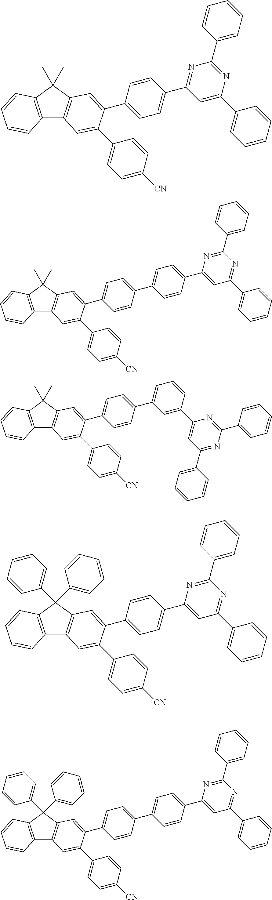
- the compound of Chemical Formula 1 has a structure in which substituents substitute No. 2 and No. 3 carbons among the substitutable carbon positions of the fluorene core.
- substituents having favorable electron injection properties such as triazine, pyrimidine or pyridine bond to the No. 2 position of the fluorene core, and additionally, a substituent bond at the adjacent No. 3 position.
- the substituents bond at adjacent positions of the fluorene core causing steric hindrance, and due to the steric hindrance, the compounds of the present disclosure have a distorted molecular structure. This increases structural stability, and therefore, when using the compounds of the present disclosure in a device, a lifetime of the device is enhanced and efficiency of the device increases.
- substituted or unsubstituted means being substituted with one or more substituents selected from the group consisting of deuterium, a halogen group, a nitrile group, a nitro group, a hydroxyl group, a silyl group, a boron group, an alkyl group, a cycloalkyl group, an aralkyl group, an alkoxy group, an alkenyl group, an aralkenyl group, a phosphine oxide group, an arylphosphine group, an aryloxy group, an alkylthioxy group, an arylthioxy group, an alkylsulfoxy group, an arylsulfoxy group, an aryl group, an alkylaryl group, and a heteroaryl group or being unsubstituted, or being substituted with a substituent linking two or more substituents of the above-illustrated substituents or being unsubstit
- the heteroarylaryl group can be an aryl group, or can be interpreted as a substituent linking a heteroaryl group and an aryl group.
- a group linking three substituents include an aryl group substituted with a heteroaryl group substituted with an aryl group, an aryl group substituted with an aryl group substituted with a heteroaryl group, a heteroaryl group substituted with an aryl group substituted with a heteroaryl group, and the like.
- substituted or unsubstituted means being substituted with one or more substituents selected from the group consisting of deuterium, a nitrile group, a halogen group, an alkyl group, a cycloalkyl group, an aralkyl group, an alkenyl group, an aralkenyl group, an aryl group, and an arylalkyl group or being unsubstituted, or being substituted with a substituent linking two or more substituents of the above-illustrated substituents or being unsubstituted.
- examples of the halogen group include fluorine, chlorine, bromine or iodine.
- the silyl group can have a chemical formula of —SiRxRyRz, and Rx, Ry and Rz each independently can be hydrogen, a substituted or unsubstituted alkyl group, or a substituted or unsubstituted aryl group.
- Rx, Ry and Rz each independently can be hydrogen, a substituted or unsubstituted alkyl group, or a substituted or unsubstituted aryl group.
- Specific examples of the silyl group can include a trimethylsilyl group, a triethylsilyl group, a t-butyldimethylsilyl group, a vinyldimethylsilyl group, a propyldimethylsilyl group, a triphenylsilyl group, a diphenylsilyl group, a phenylsilyl group and the like, but are not limited thereto.
- the boron group can have a chemical formula of —BR 100 R 101 , and R 100 and R 101 each independently can be hydrogen, a substituted or unsubstituted alkyl group, or a substituted or unsubstituted aryl group.
- R 100 and R 101 each independently can be hydrogen, a substituted or unsubstituted alkyl group, or a substituted or unsubstituted aryl group.
- Specific examples of the boron group can include a dimethylboron group, a diethylboron group, a t-butylethylboron group, a diphenylboron group, a phenylboron group and the like, but are not limited thereto.
- the alkoxy group means a group in which an alkyl group bonds to an oxygen atom, and although not particularly limited thereto, the number of carbon atoms is preferably from 1 to 40. According to one embodiment, the number of carbon atoms of the alkoxy group is from 1 to 10. According to another embodiment, the number of carbon atoms of the alkoxy group is from 1 to 6. Specific examples of the alkoxy group can include a methoxy group, an ethoxy group, a propoxy group, an isobutyloxy group, a sec-butyloxy group, a pentyloxy group, an iso-amyloxy group, a hexyloxy group and the like, but are not limited thereto.
- the alkyl group can be linear or branched, and although not particularly limited thereto, the number of carbon atoms is preferably from 1 to 40. According to one embodiment, the number of carbon atoms of the alkyl group is from 1 to 20. According to another embodiment, the number of carbon atoms of the alkyl group is from 1 to 10. According to another embodiment, the number of carbon atoms of the alkyl group is from 1 to 6.
- alkyl group can include methyl, ethyl, propyl, n-propyl, isopropyl, butyl, n-butyl, isobutyl, tert-butyl, sec-butyl, 1-methylbutyl, 1-ethylbutyl, pentyl, n-pentyl, isopentyl, neopentyl, tert-pentyl, hexyl, n-hexyl, 1-methylpentyl, 2-methylpentyl, 3,3-dimethylbutyl, 2-ethylbutyl, heptyl, n-heptyl, octyl, n-octyl, tert-octyl, 1-methylheptyl, 2-ethylhexyl, 2-propylpentyl, n-nonyl, 2,2-dimethylheptyl, 1-ethylpropyl,
- the cycloalkyl group means a cyclic hydrocarbon group, and although not particularly limited thereto, the number of carbons is preferably from 3 to 60. According to one embodiment, the number of carbon atoms of the cycloalkyl group is from 3 to 30. According to another embodiment, the number of carbon atoms of the cycloalkyl group is from 3 to 20. According to another embodiment, the number of carbon atoms of the cycloalkyl group is from 3 to 6.
- Specific examples thereof can include cyclopropyl, cyclobutyl, cyclopentyl, 3-methyl-cyclopentyl, 2,3-dimethylcyclopentyl, cyclohexyl, 3-methyl-cyclohexyl, 4-methylcyclohexyl, 2,3-dimethylcyclohexyl, 3,4,5-trimethylcyclohexyl, 4-tert-butylcyclohexyl, cycloheptyl, cyclooctyl and the like, but are not limited thereto.
- the alkenyl group represents a linear or branched unsaturated hydrocarbon group, and although not particularly limited thereto, the number of carbon atoms is preferably from 2 to 30. According to one embodiment, the number of carbon atoms of the alkenyl group is from 2 to 20. Specific examples thereof can include ethenyl, vinyl, propenyl, allyl, isopropenyl, butenyl, isobutenyl, n-pentenyl and n-hexenyl, but are not limited thereto.
- the aralkenyl group means an alkenyl group substituted with an aryl group.
- the aryl group means totally or partially unsaturated substituted or unsubstituted monocyclic or polycyclic.
- the number of carbon atoms is preferably from 6 to 60, and the aryl group can be a monocyclic aryl group or a polycyclic aryl group. According to one embodiment, the number of carbon atoms of the aryl group is from 6 to 40. According to one embodiment, the number of carbon atoms of the aryl group is from 6 to 30.
- the aryl group can be a monocyclic aryl group or a polycyclic aryl group.
- Examples of the monocyclic aryl group can include a phenyl group, a biphenyl group, a terphenyl group and the like, but are not limited thereto.
- Examples of the polycyclic aryl group can include a naphthyl group, an anthracenyl group, a phenanthrenyl group, a perylenyl group, a fluoranthenyl group, a triphenylenyl group, a phenalenyl group, a pyrenyl group, a tetracenyl group, a chrysenyl group, a pentacenyl group, a fluorenyl group, an indenyl group, an acenaphthylenyl group, a benzofluorenyl group, a spirofluorenyl group and the like, but are not limited thereto.
- the fluorenyl group can be substituted, and two substituents bond to each other to form a spiro structure.
- substituted fluorenyl group examples include
- the heteroaryl group is a cyclic group including one or more of N, O and S as a heteroatom, and although not particularly limited thereto, the number of carbon atoms is preferably from 2 to 40. According to one embodiment, the number of carbon atoms of the heteroaryl group is from 2 to 30. According to another embodiment, the number of carbon atoms of the heteroaryl group is from 2 to 20.
- heteroaryl group can include a thiophenyl group, a furanyl group, a pyrrolyl group, an imidazolyl group, a thiazolyl group, an oxazolyl group, an oxadiazolyl group, a triazolyl group, a pyridinyl group, a bipyridinyl group, a pyrimidinyl group, a triazinyl group, a triazolyl group, an acridinyl group, a carbolinyl group, an acenaphthoquinoxalinyl group, an indenoquinazolinyl group, an indenoisoquinolinyl group, an indenoquinolinyl group, a pyridoindolyl group, a pyridazinyl group, a pyrazinyl group, a quinolinyl group, a quinazolinyl group, a quinox
- the alkylaryl group means an aryl group substituted with an alkyl group.
- alkyl group in the alkylthioxy group, the alkylsulfoxy group and the alkylaryl group.
- aryl group in the aralkenyl group, the arylphosphine group, the aryloxy group, the arylthioxy group and the arylsulfoxy group.
- the “adjacent” group can mean a substituent substituting an atom directly linked to an atom substituted by the corresponding substituent, a substituent sterically most closely positioned to the corresponding substituent, or another substituent substituting an atom substituted by the corresponding substituent.
- two substituents substituting ortho positions in a benzene ring, and two substituents substituting the same carbon in an aliphatic ring can be interpreted as groups “adjacent” to each other.
- the meaning of bonding to adjacent groups to form a ring means bonding to adjacent groups to form a substituted or unsubstituted aliphatic hydrocarbon ring, a substituted or unsubstituted aromatic hydrocarbon ring, a substituted or unsubstituted aliphatic heteroring, a substituted or unsubstituted aromatic heteroring, or a fused ring thereof.
- the hydrocarbon ring means a ring formed only with carbon and hydrogen atoms, and the hydrocarbon ring can be an aliphatic hydrocarbon ring or an aromatic hydrocarbon ring.
- the heteroring means a ring including one or more of heteroatoms, and the heteroring can be an aliphatic heteroring or an aromatic heteroring.
- the aliphatic hydrocarbon ring, the aromatic hydrocarbon ring, the aliphatic heteroring and the aromatic heteroring can be monocyclic or polycyclic.
- the aliphatic hydrocarbon ring means a ring formed only with carbon and hydrogen atoms as a ring that is not aromatic.
- Examples of the aliphatic hydrocarbon ring include cyclopropane, cyclobutane, cyclobutene, cyclopentane, cyclopentene, cyclohexane, cyclohexene, 1,4-cyclohexadiene, cycloheptane, cycloheptene, cyclooctane, cyclooctene and the like, but are not limited thereto.
- the aromatic hydrocarbon ring means an aromatic ring formed only with carbon and hydrogen atoms.
- Examples of the aromatic hydrocarbon ring include benzene, naphthalene, anthracene, phenanthrene, perylene, fluoranthene, triphenylene, phenalene, pyrene, tetracene, chrysene, pentacene, fluorene, indene, acenaphthalene, benzofluorene, spirofluorene and the like, but are not limited thereto.
- the aliphatic heteroring means an aliphatic ring including one or more of heteroatoms.
- Examples of the aliphatic heteroring include oxirane, tetrahydrofuran, 1,4-dioxane, pyrrolidine, piperidine, morpholine, oxepane, azocane, thiocane and the like, but are not limited thereto.
- the aromatic heteroring means an aromatic ring including one or more of heteroatoms.
- the aromatic heteroring include pyridine, pyrrole, pyrimidine, pyridazine, furan, thiophene, imidazole, pyrazole, oxazole, isoxazole, thiazole, isothiazole, triazole, oxadiazole, thiadiazole, dithiazole, tetrazole, pyran, thiopyran, diazine, oxazine, thiazine, dioxin, triazine, tetrazine, isoquinoline, quinoline, quinol, quinazoline, quinoxaline, naphthridine, acridine, phenanthridine, diazanaphthalene, triazaindene, indole, indolizine, benzothiazole, benzoxazole, benzimidazole, benzothiophene
- R1 and R2 are the same as or different from each other, and each independently is hydrogen, deuterium, a substituted or unsubstituted alkyl group having 1 to 30 carbon atoms, or a substituted or unsubstituted aryl group having 6 to 30 carbon atoms.
- R1 and R2 are the same as or different from each other, and each independently is hydrogen, deuterium, a substituted or unsubstituted alkyl group having 1 to 20 carbon atoms, or a substituted or unsubstituted aryl group having 6 to 20 carbon atoms.
- R1 and R2 are the same as or different from each other, and each independently is hydrogen, deuterium, a substituted or unsubstituted alkyl group having 1 to 10 carbon atoms, or a substituted or unsubstituted aryl group having 6 to 10 carbon atoms.
- R1 and R2 are the same as or different from each other, and each independently is hydrogen, deuterium, an alkyl group having 1 to 10 carbon atoms, or an aryl group having 6 to 10 carbon atoms.
- R1 and R2 are the same as or different from each other, and each independently is a substituted or unsubstituted methyl group, or a substituted or unsubstituted phenyl group, or bond to each other to form a substituted or unsubstituted fluorene ring.
- the linking sites of R1 and R2 are each a single bond site of the fluorene pentagonal ring.
- R1 and R2 are the same as or different from each other, and each independently is a methyl group, or a phenyl group, or bond to each other to form a fluorene ring.
- R3 is hydrogen or deuterium.
- X1 is N
- X2 is CRb
- X3 is CRc
- X1 is CRa
- X2 is N
- X3 is CRc
- X1 is CRa
- X2 is CRb
- X3 is N.
- X1 is N
- X2 is N
- X3 is CRc
- X1 is N
- X2 is CRb
- X3 is N
- X1 is CRa
- X2 is N
- X3 is N
- X1 is N
- X2 is N
- X3 is N
- Ra is hydrogen or deuterium.
- Rb is hydrogen or deuterium.
- Rc is hydrogen or deuterium.
- L is a substituted or unsubstituted arylene group having 6 to 30 carbon atoms.
- L is an arylene group having 6 to 30 carbon atoms unsubstituted or substituted with deuterium, an alkyl group or an aryl group.
- L is a substituted or unsubstituted arylene group having 6 to 24 carbon atoms.
- L is a substituted or unsubstituted arylene group having 6 to 12 carbon atoms.
- L is a substituted or unsubstituted phenylene group, a substituted or unsubstituted biphenylene group, a substituted or unsubstituted terphenylene group, a substituted or unsubstituted quaterphenylene group, a substituted or unsubstituted naphthylene group, a substituted or unsubstituted anthracenylene group, a substituted or unsubstituted pyrenylene group, a substituted or unsubstituted phenanthrenylene group, a substituted or unsubstituted perylenylene group, a substituted or unsubstituted tetracenylene group, a substituted or unsubstituted triphenylene group, a substituted or unsubstituted fluoranthenylene group, or a substituted or unsubstituted fluorenylene group.
- L is a phenylene group unsubstituted or substituted with deuterium, an alkyl group or an aryl group; a biphenylene group unsubstituted or substituted with deuterium, an alkyl group or an aryl group; a terphenylene group unsubstituted or substituted with deuterium, an alkyl group or an aryl group; a quaterphenylene group unsubstituted or substituted with deuterium, an alkyl group or an aryl group; a naphthylene group unsubstituted or substituted with deuterium, an alkyl group or an aryl group; an anthracenylene group unsubstituted or substituted with deuterium, an alkyl group or an aryl group; a pyrenylene group unsubstituted or substituted with deuterium, an alkyl group or an aryl group; a phenanthreny
- L is a substituted or unsubstituted phenylene group or a substituted or unsubstituted biphenylene group.
- L is a phenylene group unsubstituted or substituted with deuterium, an alkyl group or an aryl group; or a biphenylene group unsubstituted or substituted with deuterium, an alkyl group or an aryl group.
- L is a phenylene group or a biphenylene group.
- L is a p-phenylene group.
- L is an m-phenylene group.
- L is
- L is
- L is
- n is 2 or greater, and at least one of the two or more Ls is a substituted or unsubstituted m-phenylene group.
- n is 2 or greater, and at least one of the two or more Ls is an m-phenylene group unsubstituted or substituted with deuterium, an alkyl group or an aryl group.
- Chemical Formula 1 is any one of the following Chemical Formulae 1-A to 1-C:
- R11 is hydrogen
- R12 is hydrogen
- R13 is hydrogen
- Chemical Formula 1 is Chemical Formula 2:
- R1, R2, R3, X1, X2, X3, Ar1, Ar2, a3 and n have the same definitions as in Chemical Formula 1;
- n is an integer of 1 to 4.
- n is an integer of 1 to 3.
- n 1
- n is 2.
- Ar1 and Ar2 are the same as or different from each other, and each independently is a substituted or unsubstituted alkyl group having 1 to 30 carbon atoms, a substituted or unsubstituted aryl group having 6 to 30 carbon atoms, or a substituted or unsubstituted heteroaryl group having 2 to 30 carbon atoms.
- Ar1 and Ar2 are the same as or different from each other, and each independently is a substituted or unsubstituted alkyl group having 1 to 20 carbon atoms, a substituted or unsubstituted aryl group having 6 to 24 carbon atoms, or a substituted or unsubstituted heteroaryl group having 2 to 24 carbon atoms.
- Ar1 and Ar2 are the same as or different from each other, and each independently is a substituted or unsubstituted alkyl group having 1 to 10 carbon atoms, a substituted or unsubstituted aryl group having 6 to 20 carbon atoms, or a substituted or unsubstituted heteroaryl group having 2 to 20 carbon atoms.
- Ar1 and Ar2 are the same as or different from each other, and each independently is a substituted or unsubstituted aryl group having 6 to 30 carbon atoms.
- Ar1 and Ar2 are the same as or different from each other, and each independently is a substituted or unsubstituted aryl group having 6 to 24 carbon atoms.
- Ar1 and Ar2 are the same as or different from each other, and each independently is a substituted or unsubstituted aryl group having 6 to 20 carbon atoms.
- Ar1 and Ar2 are the same as or different from each other, and each independently is an aryl group unsubstituted or substituted with a nitrile group or an aryl group.
- At least one of Ar1 and Ar2 is an aryl group substituted with a nitrile group.
- Ar1 and Ar2 are the same as or different from each other, and each independently is a substituted or unsubstituted phenyl group, or a substituted or unsubstituted biphenyl group.
- Ar1 and Ar2 are the same as or different from each other, and each independently is a phenyl group unsubstituted or substituted with a nitrile group or an aryl group, or a biphenyl group unsubstituted or substituted with an aryl group.
- Ar1 and Ar2 are the same as or different from each other, and each independently is a phenyl group unsubstituted or substituted with a nitrile group, or a biphenyl group.
- Ar1 and Ar2 are the same as or different from each other, and each independently is a phenyl group, a 4-nitrilephenyl group or a biphenyl group.
- Ar3 is a substituted or unsubstituted aryl group having 6 to 30 carbon atoms, or a substituted or unsubstituted heteroaryl group having 2 to 30 carbon atoms.
- Ar3 is an aryl group having 6 to 30 carbon atoms unsubstituted or substituted with an aryl group, or a heteroaryl group having 2 to 30 carbon atoms unsubstituted or substituted with an aryl group.
- Ar3 is a substituted or unsubstituted aryl group having 6 to 24 carbon atoms, or a substituted or unsubstituted heteroaryl group having 2 to 24 carbon atoms.
- Ar3 is a substituted or unsubstituted aryl group having 6 to 18 carbon atoms, or a substituted or unsubstituted heteroaryl group having 2 to 20 carbon atoms.
- Ar3 is a substituted or unsubstituted aryl group having 6 to 18 carbon atoms, or a substituted or unsubstituted heteroaryl group having 2 to 20 carbon atoms and comprising O or S.
- Ar3 is a substituted or unsubstituted phenyl group, a substituted or unsubstituted biphenyl group, a substituted or unsubstituted naphthyl group, a substituted or unsubstituted dibenzofuranyl group, or a substituted or unsubstituted dibenzothiophenyl group.
- Ar3 is a phenyl group unsubstituted or substituted with a nitrile group or an aryl group, a biphenyl group unsubstituted or substituted with an aryl group, a naphthyl group unsubstituted or substituted with an aryl group, a dibenzofuranyl group unsubstituted or substituted with an aryl group, or a dibenzothiophenyl group unsubstituted or substituted with an aryl group.
- Ar3 is a phenyl group, a 4-nitrilephenyl group, a biphenyl group, a naphthyl group, a dibenzofuranyl group, or a dibenzothiophenyl group.
- Chemical Formula 1 can be the following Chemical Formula 3:
- R6 is hydrogen
- R7 is hydrogen
- L is a biphenyl group
- the nitrogen-containing 6-membered heteroring and the fluorene are localized, and electron and hole flows can be more controlled.
- the compound in which L is a biphenyl group has excellent bipolar properties, and a device lifetime can be more improved.
- a driving voltage is low, device efficiency is high and a lifetime is enhanced compared to devices using compounds in which L is other biphenyl groups.
- the compound of Chemical Formula 1 is any one compound selected from among the following compounds:
- the compound of Chemical Formula 1 described above can be prepared according to the following General Formula 1.
- the method for preparing the compound of Chemical Formula 1 is not limited to the following General Formula 1, and methods known in the art can be used in the preparation, and types, positions or the number of substituents can vary depending on technologies known in the art.
- R1, R2, R3, X1, X2, X3, Ar1, Ar2, Ar3, L, a3 and n have the same definitions as in Chemical Formula 1.
- Another embodiment of the present specification provides an organic light emitting device comprising the compound of Chemical Formula 1.
- One embodiment of the present specification provides an organic light emitting device comprising a first electrode, a second electrode, and one or more organic material layers disposed between the first electrode and the second electrode, wherein at least one of the organic material layers comprises the compound of Chemical Formula 1.
- the first electrode is an anode
- the second electrode is a cathode
- the first electrode is a cathode
- the second electrode is an anode
- the organic material layer of the organic light emitting device of the present specification can be formed in a single layer structure, but can also be formed in a multilayer structure in which two or more organic material layers are laminated.
- the organic light emitting device of the present disclosure can have a structure including a hole injection layer, a hole transfer layer, a light emitting layer, an electron transfer layer, an electron injection layer and the like as the organic material layer.
- the structure of the organic light emitting device is not limited thereto, and can include less numbers of organic layers.
- the organic material layer comprises at least one of an electron injection layer, an electron transfer layer and a layer carrying out electron injection and transfer at the same time, and at least one of the electron injection layer, the electron transfer layer and the layer carrying out electron injection and transfer at the same time comprises the compound.
- the organic material layer comprises a light emitting layer
- the light emitting layer comprises the compound of Chemical Formula 1.
- the organic material layer comprises a light emitting layer
- the light emitting layer comprises the compound of Chemical Formula 1 as a host.
- the organic light emitting device is a green organic light emitting device
- the organic material layer comprises the compound of Chemical Formula 1 as a host of a light emitting layer.
- the compound of Chemical Formula 1 when X1 to X3 are N, the compound of Chemical Formula 1 can be included in a light emitting layer of the organic material layer of the organic light emitting device as a host.
- the organic material layer comprises a hole blocking layer
- the hole blocking layer comprises the compound of Chemical Formula 1.
- the organic material layer comprises an electron control layer
- the electron control layer comprises the compound of Chemical Formula 1.
- the organic light emitting device can be an organic light emitting device having a structure in which an anode, one or more organic material layers and a cathode are consecutively laminated on a substrate (normal type).
- the organic light emitting device can be an organic light emitting device having a structure in a reverse direction in which a cathode, one or more organic material layers and an anode are consecutively laminated on a substrate (inverted type).
- the organic light emitting device of the present specification can have a lamination structure as follows, however, the structure is not particularly limited thereto.
- FIG. 1 illustrates an example of the organic light emitting device formed with a substrate ( 1 ), an anode ( 2 ), a light emitting layer ( 6 ) and a cathode ( 10 ).
- the compound can be included in the light emitting layer.
- FIG. 2 illustrates an example of the organic light emitting device formed with a substrate ( 1 ), an anode ( 2 ), a hole injection layer ( 3 ), a hole transfer layer ( 4 ), an electron blocking layer ( 5 ), alight emitting layer ( 6 ), a hole blocking layer ( 7 ), an electron transfer layer ( 8 ), an electron injection layer ( 9 ) and a cathode ( 10 ).
- the compound can be included in at least one of the light emitting layer, the hole blocking layer, the electron transfer layer and the electron injection layer.
- the compound of Chemical Formula 1 is included in the hole blocking layer.
- the organic light emitting device of the present specification can be manufactured using materials and methods known in the art, except that one or more layers of the organic material layers include the compound of the present specification, that is, the compound of Chemical Formula 1.
- the organic material layers can be formed with materials the same as or different from each other.
- the organic light emitting device of the present specification can be manufactured by consecutively laminating a first electrode, an organic material layer and a second electrode on a substrate.
- the organic light emitting device can be manufactured by forming an anode on a substrate by depositing a metal, a metal oxide having conductivity, or an alloy thereof using a physical vapor deposition (PVD) method such as sputtering or e-beam evaporation, and forming an organic material layer including a hole injection layer, a hole transfer layer, a light emitting layer and an electron transfer layer thereon, and then depositing a material capable of being used as a cathode thereon.
- PVD physical vapor deposition
- the organic light emitting device can also be manufactured by consecutively depositing a cathode material, an organic material layer and an anode material on a substrate.
- the compound of Chemical Formula 1 can be formed into an organic material layer using a solution coating method as well as a vacuum deposition method when manufacturing the organic light emitting device.
- the solution coating method means spin coating, dip coating, doctor blading, inkjet printing, screen printing, a spray method, roll coating and the like, but is not limited thereto.
- the organic light emitting device can also be manufactured by consecutively laminating a cathode material, an organic material layer and an anode material on a substrate (International Patent Application Publication No. WO2003/012890).
- the manufacturing method is not limited thereto.
- anode material materials having large work function are normally preferred so that hole injection to an organic material layer is smooth.
- the anode material capable of being used in the present disclosure include metals such as vanadium, chromium, copper, zinc and gold, or alloys thereof; metal oxides such as zinc oxide, indium oxide, indium tin oxide (ITO) and indium zinc oxide (IZO); combinations of metals and oxides such as ZnO:Al or SnO 2 :Sb; conductive polymers such as poly(3-methylthiophene), poly[3,4-(ethylene-1,2-dioxy)thiophene] (PEDOT), polypyrrole and polyaniline, but are not limited thereto.
- the cathode material materials having small work function are normally preferred so that electron injection to an organic material layer is smooth.
- the cathode material include metals such as magnesium, calcium, sodium, potassium, titanium, indium, yttrium, lithium, gadolinium, aluminum, silver, tin and lead, or alloys thereof; multilayer structure materials such as LiF/Al or LiO 2 /Al, and the like, but are not limited thereto.
- the hole injection layer is a layer that injects holes from an electrode
- the hole injection material is preferably a compound that has an ability to transfer holes, therefore, has a hole injection effect in an anode, has an excellent hole injection effect for a light emitting layer or a light emitting material, prevents excitons generated in the light emitting layer from moving to an electron injection layer or an electron injection material, and in addition thereto, has an excellent thin film forming ability.
- the highest occupied molecular orbital (HOMO) of the hole injection material is preferably in between the work function of an anode material and the HOMO of surrounding organic material layers.
- the hole injection material examples include metal porphyrins, oligothiophene, arylamine-based organic materials, hexanitrile hexaazatriphenylene-based organic materials, quinacridone-based organic materials, perylene-based organic materials, anthraquinone, and polyaniline- and polythiophene-based conductive polymers, and the like, but are not limited thereto.
- the hole transfer layer is a layer that receives holes from a hole injection layer and transfers the holes to a light emitting layer
- the hole transfer material materials capable of receiving holes from an anode or a hole injection layer, moving the holes to a light emitting layer, and having high mobility for the holes are suited.
- Specific examples thereof include arylamine-based organic materials, conductive polymers, block copolymers having conjugated parts and non-conjugated parts together, and the like, but are not limited thereto.
- the electron blocking layer is a layer capable of enhancing lifetime and efficiency of a device by preventing electrons injected from an electron injection layer from passing through a light emitting layer and entering a hole injection layer.
- the electron blocking layer can be formed in a proper part between the light emitting layer and the hole injection layer using known materials.
- the electron blocking material hole transfer materials can be used, however, the electron blocking material is not limited thereto.
- the electron blocking layer is formed using arylamine-based organic materials.
- the hole blocking layer is a layer capable of enhancing lifetime and efficiency of a device by preventing holes injected from a hole injection layer from passing through a light emitting layer and entering an electron injection layer, and can be formed as necessary in a proper part between the light emitting layer and the electron injection layer using known materials.
- the hole blocking layer can be formed by vacuum thermal depositing and spin coating a hole blocking material using common methods, and as the hole blocking material, oxadiazole derivatives, triazole derivatives, phenanthroline derivatives, BCP, aluminum complexes and the like can be specifically used, however, the hole blocking material is not limited thereto.
- the light emitting material is a material capable of emitting light in a visible light region by receiving holes and electrons from a hole transfer layer and an electron transfer layer, respectively, and binding the holes and the electrons, and is preferably a material having favorable quantum efficiency for fluorescence or phosphorescence.
- Specific examples thereof include 8-hydroxyquinoline aluminum complexes (Alq 3 ), carbazole-based compounds, dimerized styryl compounds, BAlq, 10-hydroxybenzoquinoline-metal compounds, benzoxazole-, benzthiazole- and benzimidazole-based compounds, poly(p-phenylenevinylene) (PPV)-based polymers, spiro compounds, polyfluorene, rubrene, and the like, but are not limited thereto.
- Alq 3 8-hydroxyquinoline aluminum complexes
- carbazole-based compounds dimerized styryl compounds
- BAlq 10-hydroxybenzoquinoline-metal compounds
- benzoxazole-, benzthiazole- and benzimidazole-based compounds benzoxazole-, benzthiazole- and benzimidazole-based compounds
- PV poly(p-phenylenevinylene)-based polymers
- spiro compounds polyfluorene, rubrene, and
- the light emitting layer can include a host material and a dopant material.
- the host material includes fused aromatic ring derivatives, heteroring-containing compounds or the like.
- the fused aromatic ring derivative includes anthracene derivatives, pyrene derivatives, naphthalene derivatives, pentacene derivatives, phenanthrene compounds, fluoranthene compounds and the like
- the heteroring-containing compound includes carbazole derivatives, dibenzofuran derivatives, ladder-type furan compounds, pyrimidine derivatives and the like, however, the material is not limited thereto.
- the dopant material includes aromatic amine derivatives, styrylamine compounds, boron complexes, fluoranthene compounds, metal complexes and the like.
- the aromatic amine derivative is a fused aromatic ring derivative having a substituted or unsubstituted arylamine group and includes arylamine group-including pyrene, anthracene, chrysene, peryflanthene and the like
- the styrylamine compound is a compound in which substituted or unsubstituted arylamine is substituted with at least one arylvinyl group, and one, two or more substituents selected from the group consisting of an aryl group, a silyl group, an alkyl group, a cycloalkyl group and an arylamine group are substituted or unsubstituted.
- styrylamine styryldiamine, styryltriamine, styryltetramine or the like is included, however, the styrylamine compound is not limited thereto.
- the metal complex includes iridium complexes, platinum complexes or the like, but is not limited thereto.
- the electron transfer layer is a layer that receives electrons from an electron injection layer and transfers the electrons to a light emitting layer
- materials capable of favorably receiving electrons from a cathode, moving the electrons to a light emitting layer, and having high mobility for the electrons are suited.
- Specific examples thereof include Al complexes of 8-hydroxyquinoline, complexes including Alq 3 , organic radical compounds, hydroxyflavon-metal complexes, and the like, but are not limited thereto.
- the electron transfer layer can be used together with any desired cathode material as used in the art.
- the suitable cathode material include common materials that have small work function, and in which an aluminum layer or a silver layer follows.
- the cathode material includes cesium, barium, calcium, ytterbium and samarium, and in each case, an aluminum layer or a silver layer follows.
- the electron injection layer is a layer that injects electrons from an electrode
- the electron injection material is preferably a compound that has an ability to transfer electrons, has an electron injection effect from a cathode, has an excellent electron injection effect for a light emitting layer or a light emitting material, prevents excitons generated in the light emitting layer from moving to a hole injection layer, and in addition thereto, has an excellent thin film forming ability.
- fluorenone anthraquino-dimethane, diphenoquinone, thiopyran dioxide, oxazole, oxadiazole, triazole, imidazole, perylene tetracarboxylic acid, fluorenylidene methane, anthrone or the like, and derivatives thereof, triazine derivatives, metal complex compounds, nitrogen-containing 5-membered ring derivatives, and the like, but are not limited there.
- the metal complex compound includes 8-hydroxyquinolinato lithium, bis(8-hydroxyquinolinato)zinc, bis(8-hydroxy-quinolinato)copper, bis(8-hydroxyquinolinato)manganese, tris(8-hydroxyquinolinato)aluminum, tris(2-methyl-8-hydroxy-quinolinato)aluminum, tris(8-hydroxyquinolinato)gallium, bis(10-hydroxybenzo[h]quinolinato)berylium, bis(10-hydroxybenzo[h]quinolinato)zinc, bis(2-methyl-8-quinolinato)-chloro-gallium, bis(2-methyl-8-quinolinato)(o-cresolato)-gallium, bis(2-methyl-8-quinolinato)(1-naphtholato)aluminum, bis(2-methyl-8-quinolinato) (2-naphtholato)gallium and the like, but is not limited thereto.
- the organic light emitting device can be a top-emission type, a bottom-emission type or a dual-emission type depending on the materials used.
- a glass substrate on which indium tin oxide (ITO) was coated as a thin film to a thickness of 1,000 ⁇ was placed in detergent-dissolved distilled water and ultrasonically cleaned.
- a product of Fischer Co. was used as the detergent, and as the distilled water, distilled water filtered twice with a filter manufactured by Millipore Co. was used. After the ITO was cleaned for 30 minutes, ultrasonic cleaning was repeated twice using distilled water for 10 minutes. After the cleaning with distilled water was finished, the substrate was ultrasonically cleaned with solvents of isopropyl alcohol, acetone and methanol, then dried, and then transferred to a plasma cleaner. The substrate was cleaned for 5 minutes using oxygen plasma, and then transferred to a vacuum deposition apparatus.
- a hole injection layer was formed by thermal vacuum depositing compounds of the following Compound HI1 and the following Compound HI2 in a ratio of 98:2 (molar ratio) to a thickness of 100 ⁇ .
- a hole transfer layer was formed by vacuum depositing a compound of the following Chemical Formula HT1 (1150 ⁇ ).
- an electron blocking layer was formed on the hole transfer layer by vacuum depositing a compound of EB1 shown below to a film thickness of 50 ⁇ .
- a light emitting layer was formed on the electron blocking layer by vacuum depositing a compound of the following Chemical Formula BH and a compound of the following Chemical Formula BD in a weight ratio of 50:1 to a film thickness of 200 ⁇ .
- a hole blocking layer was formed by vacuum depositing Compound 1 to a film thickness of 50 ⁇ .
- an electron injection and transfer layer was formed on the hole blocking layer to a thickness of 30 ⁇ by vacuum depositing a compound of the following Chemical Formula ET1 and a compound of the following Chemical Formula LiQ in a weight ratio of 1:1.
- a cathode was formed by consecutively depositing lithium fluoride (LiF) to a thickness of 12 ⁇ and aluminum to a thickness of 1,000 ⁇ .
- the deposition rates of the organic materials were maintained at 0.4 ⁇ /sec to 0.7 ⁇ /sec, the deposition rates of the lithium fluoride and the aluminum of the cathode were maintained at 0.3 ⁇ /sec and 2 ⁇ /sec, respectively, and the degree of vacuum during the deposition was maintained at 2 ⁇ 10 ⁇ 7 torr to 5 ⁇ 10 ⁇ 6 torr to manufacture an organic light emitting device.
- Organic light emitting devices were manufactured in the same manner as in Example 1-1 except that compounds described in the following Table 1 were used as the hole blocking layer instead of Compound 1.
- T95 means time taken for luminance decreasing to 95% from initial luminance (1600 nit).
- the organic light emitting device using the compound of the present disclosure as a hole blocking layer exhibited superior properties in terms of efficiency, driving voltage and stability of the organic light emitting device.
- Examples 1-1 to 1-18 as shown in Table 1, it was seen that, when using a material in which the No. 2 carbon position of the fluorene core was substituted with triazine, pyrimidine or pyridine through an aryl group as a hole blocking layer, the device had properties of low voltage, high efficiency and long lifetime.
- the compound according to the present disclosure has an excellent hole blocking ability, and is usable in an organic light emitting device.
- the device had a lower driving voltage and higher efficiency.
- Example 1-18 of Table 1 it was identified that the lifetime was the longest when using a compound in which a triazine group including a CN group as substituent bonds to the fluorene core as a hole blocking layer.
- the CN group in the compound greatly enhances a device lifetime by slightly slowing electron injection into a light emitting layer in a hole blocking layer.
Landscapes
- Chemical & Material Sciences (AREA)
- Organic Chemistry (AREA)
- Engineering & Computer Science (AREA)
- Materials Engineering (AREA)
- Physics & Mathematics (AREA)
- Spectroscopy & Molecular Physics (AREA)
- Optics & Photonics (AREA)
- Electroluminescent Light Sources (AREA)
Abstract

-
- wherein X1 is N or CRa, X2 is N or CRb, X3 is N or CRc, and one or more of X1 to X3 are N;
- Ar1 and Ar2 each independently is a substituted or unsubstituted alkyl, aryl group, or heteroaryl group;
- Ar3 is a substituted or unsubstituted aryl or heteroaryl group;
- L is a substituted or unsubstituted arylene group;
- R1 and R2 each independently is hydrogen, deuterium, or a substituted or unsubstituted alkyl or aryl group, or bond to each other to form a ring;
- R3 and Ra to Rc each independently is a hydrogen, deuterium, halogen, nitrile, nitro, hydroxyl, or a substituted or unsubstituted group selected from among a silyl, boron, alkyl, cycloalkyl, alkoxy, aryloxy, alkylthioxy, arylthioxy, alkylsulfoxy, arylsulfoxy, alkenyl, aralkyl, aralkenyl, alkylaryl, arylphosphine, phosphine oxide, aryl, or a heteroaryl group, or bond to adjacent groups to form a ring;
- a3 is 1 to 6; and
- n is 1 to 5,
- and an organic light emitting device comprising the same.
Description

-
- X1 is N or CRa, X2 is N or CRb, X3 is N or CRc, and one or more of X1 to X3 are N;
- Ar1 and Ar2 are the same as or different from each other, and each independently is a substituted or unsubstituted alkyl group, a substituted or unsubstituted aryl group, or a substituted or unsubstituted heteroaryl group;
- Ar3 is a substituted or unsubstituted aryl group or a substituted or unsubstituted heteroaryl group;
- L is a substituted or unsubstituted arylene group;
- R1 and R2 are the same as or different from each other, and each independently is hydrogen, deuterium, a substituted or unsubstituted alkyl group, or a substituted or unsubstituted aryl group, or bond to each other to form a substituted or unsubstituted ring;
- R3 and Ra to Rc are the same as or different from each other, and each independently is hydrogen, deuterium, a halogen group, a nitrile group, a nitro group, a hydroxyl group, a substituted or unsubstituted silyl group, a substituted or unsubstituted boron group, a substituted or unsubstituted alkyl group, a substituted or unsubstituted cycloalkyl group, a substituted or unsubstituted alkoxy group, a substituted or unsubstituted aryloxy group, a substituted or unsubstituted alkylthioxy group, a substituted or unsubstituted arylthioxy group, a substituted or unsubstituted alkylsulfoxy group, a substituted or unsubstituted arylsulfoxy group, a substituted or unsubstituted alkenyl group, a substituted or unsubstituted aralkyl group, a substituted or unsubstituted aralkenyl group, a substituted or unsubstituted alkylaryl group, a substituted or unsubstituted arylphosphine group, a substituted or unsubstituted phosphine oxide group, a substituted or unsubstituted aryl group, or a substituted or unsubstituted heteroaryl group, or can bond to adjacent groups to form a substituted or unsubstituted ring;
- a3 is an integer of 1 to 6;
- n is an integer of 1 to 5;
- when a3 is 2 or greater, the R3s are the same as or different from each other; and
- when n is 2 or greater, the Ls are the same as or different from each other.
means a site bonding to other substituents or bonding sites.

and the like, but are not limited thereto.


-
- R3, Ar1 to Ar3, X1 to X3, L, n and a3 have the same definitions as in
Chemical Formula 1; - R11 to R13 are the same as or different from each other, and each independently is hydrogen, deuterium, a halogen group, a nitrile group, a nitro group, a hydroxyl group, a substituted or unsubstituted silyl group, a substituted or unsubstituted boron group, a substituted or unsubstituted alkyl group, a substituted or unsubstituted cycloalkyl group, a substituted or unsubstituted alkoxy group, a substituted or unsubstituted aryloxy group, a substituted or unsubstituted alkylthioxy group, a substituted or unsubstituted arylthioxy group, a substituted or unsubstituted alkylsulfoxy group, a substituted or unsubstituted arylsulfoxy group, a substituted or unsubstituted alkenyl group, a substituted or unsubstituted aralkyl group, a substituted or unsubstituted aralkenyl group, a substituted or unsubstituted alkylaryl group, a substituted or unsubstituted arylphosphine group, a substituted or unsubstituted phosphine oxide group, a substituted or unsubstituted aryl group, or a substituted or unsubstituted heteroaryl group;
- a11 and a12 are each an integer of 1 to 5;
- a13 is an integer of 1 to 8; and
- when a11 to a13 are 2 or greater, two or more substituents in the parentheses are the same as or different from each other.
- R3, Ar1 to Ar3, X1 to X3, L, n and a3 have the same definitions as in

-
- R5 is hydrogen, deuterium, a halogen group, a nitrile group, a nitro group, a hydroxyl group, a substituted or unsubstituted silyl group, a substituted or unsubstituted boron group, a substituted or unsubstituted alkyl group, a substituted or unsubstituted cycloalkyl group, a substituted or unsubstituted alkoxy group, a substituted or unsubstituted aryloxy group, a substituted or unsubstituted alkylthioxy group, a substituted or unsubstituted arylthioxy group, a substituted or unsubstituted alkylsulfoxy group, a substituted or unsubstituted arylsulfoxy group, a substituted or unsubstituted alkenyl group, a substituted or unsubstituted aralkyl group, a substituted or unsubstituted aralkenyl group, a substituted or unsubstituted alkylaryl group, a substituted or unsubstituted arylphosphine group, a substituted or unsubstituted phosphine oxide group, a substituted or unsubstituted aryl group, or a substituted or unsubstituted heteroaryl group, or can bond to adjacent groups to form a substituted or unsubstituted hydrocarbon ring;
- a5 is an integer of 1 to 4; and
- when a5 is 2 or greater, the R5s are the same as or different from each other.

-
- R1 to R3, Ar1 to Ar3, X1 to X3 and a3 have the same definitions as in
Chemical Formula 1; - R6 and R7 are the same as or different from each other, and each independently is deuterium, a halogen group, a nitrile group, a nitro group, a hydroxyl group, a substituted or unsubstituted silyl group, a substituted or unsubstituted boron group, a substituted or unsubstituted alkyl group, a substituted or unsubstituted cycloalkyl group, a substituted or unsubstituted alkoxy group, a substituted or unsubstituted aryloxy group, a substituted or unsubstituted alkylthioxy group, a substituted or unsubstituted arylthioxy group, a substituted or unsubstituted alkylsulfoxy group, a substituted or unsubstituted arylsulfoxy group, a substituted or unsubstituted alkenyl group, a substituted or unsubstituted aralkyl group, a substituted or unsubstituted aralkenyl group, a substituted or unsubstituted alkylaryl group, a substituted or unsubstituted arylphosphine group, a substituted or unsubstituted phosphine oxide group, a substituted or unsubstituted aryl group, or a substituted or unsubstituted heteroaryl group;
- a6 and a7 are each an integer of 1 to 4; and
- when a6 and a7 are 2 or greater, two or more substituents in the parentheses are the same as or different from each other.
- R1 to R3, Ar1 to Ar3, X1 to X3 and a3 have the same definitions as in

in

and a proper level of solubility is obtained readily achieving a synthesis process and decreasing a deposition temperature as well.

in a device, a driving voltage is low, device efficiency is high and a lifetime is enhanced compared to devices using compounds in which L is other biphenyl groups.


-
- (1) anode/hole transfer layer/light emitting layer/cathode
- (2) anode/hole injection layer/hole transfer layer/light emitting layer/cathode
- (3) anode/hole injection layer/hole buffer layer/hole transfer layer/light emitting layer/cathode
- (4) anode/hole transfer layer/light emitting layer/electron transfer layer/cathode
- (5) anode/hole transfer layer/light emitting layer/electron transfer layer/electron injection layer/cathode
- (6) anode/hole injection layer/hole transfer layer/light emitting layer/electron transfer layer/cathode
- (7) anode/hole injection layer/hole transfer layer/light emitting layer/electron transfer layer/electron injection layer/cathode
- (8) anode/hole injection layer/hole buffer layer/hole transfer layer/light emitting layer/electron transfer layer/cathode
- (9) anode/hole injection layer/hole buffer layer/hole transfer layer/light emitting layer/electron transfer layer/electron injection layer/cathode
- (10) anode/hole transfer layer/electron blocking layer/light emitting layer/electron transfer layer/cathode
- (11) anode/hole transfer layer/electron blocking layer/light emitting layer/electron transfer layer/electron injection layer/cathode
- (12) anode/hole injection layer/hole transfer layer/electron blocking layer/light emitting layer/electron transfer layer/cathode
- (13) anode/hole injection layer/hole transfer layer/electron blocking layer/light emitting layer/electron transfer layer/electron injection layer/cathode
- (14) anode/hole transfer layer/light emitting layer/hole blocking layer/electron transfer layer/cathode
- (15) anode/hole transfer layer/light emitting layer/hole blocking layer/electron transfer layer/electron injection layer/cathode
- (16) anode/hole injection layer/hole transfer layer/light emitting layer/hole blocking layer/electron transfer layer/cathode
- (17) anode/hole injection layer/hole transfer layer/light emitting layer/hole blocking layer/electron transfer layer/electron injection layer/cathode


| TABLE 1 | ||||||
| Compound | Effi- | |||||
| (Hole | Voltage | ciency | Color | |||
| Blocking | (V@10 | (cd/A@10 | Coordinate | T95 | ||
| Layer) | mA/cm2) | mA/cm2) | (x, y) | (hr) | ||
| Example | Compound 1 | 4.26 | 6.35 | (0.140, | 300 |
| 1-1 | 0.045) | ||||
| Example | Compound 2 | 4.33 | 6.23 | (0.141, | 275 |
| 1-2 | 0.045) | ||||
| Example | Compound 3 | 4.38 | 6.24 | (0.143, | 275 |
| 1-3 | 0.046) | ||||
| Example | Compound 4 | 4.39 | 6.25 | (0.142, | 280 |
| 1-4 | 0.045) | ||||
| Example | Compound 5 | 4.32 | 6.26 | (0.140, | 265 |
| 1-5 | 0.046) | ||||
| Example | Compound 6 | 4.36 | 6.27 | (0.141, | 290 |
| 1-6 | 0.047) | ||||
| Example | Compound 7 | 4.25 | 6.39 | (0.140, | 305 |
| 1-7 | 0.046) | ||||
| Example | Compound 8 | 4.33 | 6.18 | (0.141, | 290 |
| 1-8 | 0.047) | ||||
| Example | Compound 9 | 4.43 | 6.17 | (0.141, | 260 |
| 1-9 | 0.046) | ||||
| Example | Compound 10 | 4.37 | 6.19 | (0.140, | 285 |
| 1-10 | 0.047) | ||||
| Example | Compound 11 | 4.26 | 6.38 | (0.142, | 280 |
| 1-11 | 0.045) | ||||
| Example | Compound 12 | 4.31 | 6.14 | (0.140, | 270 |
| 1-12 | 0.046) | ||||
| Example | Compound 13 | 4.48 | 6.17 | (0.141, | 250 |
| 1-13 | 0.047) | ||||
| Example | Compound 14 | 4.43 | 6.16 | (0.142, | 275 |
| 1-14 | 0.047) | ||||
| Example | Compound 15 | 4.25 | 6.31 | (0.141, | 300 |
| 1-15 | 0.046) | ||||
| Example | Compound 16 | 4.42 | 6.10 | (0.141, | 260 |
| 1-16 | 0.046) | ||||
| Example | Compound 17 | 4.45 | 6.15 | (0.142, | 270 |
| 1-17 | 0.048) | ||||
| Example | Compound 18 | 4.52 | 6.16 | (0.141, | 325 |
| 1-18 | 0.046) | ||||
| Compar- | HB1 | 4.73 | 5.78 | (0.142, | 160 |
| ative | 0.047) | ||||
| Example | |||||
| 1-1 | |||||
| Compar- | HB2 | 5.06 | 5.52 | (0.143, | 135 |
| ative | 0.048) | ||||
| Example | |||||
| 1-2 | |||||
| Compar- | HB3 | 4.66 | 5.87 | (0.143, | 220 |
| ative | 0.048) | ||||
| Example | |||||
| 1-3 | |||||
| Compar- | HB4 | 4.94 | 5.61 | (0.143, | 185 |
| ative | 0.048) | ||||
| Example | |||||
| 1-4 | |||||

as a hole blocking layer, the device had a lower driving voltage and higher efficiency.
-
- 1: Substrate
- 2: Anode
- 3: Hole Injection Layer
- 4: Hole Transfer Layer
- 5: Electron Blocking Layer
- 6: Light Emitting Layer
- 7: Hole Blocking Layer
- 8: Electron Transfer Layer
- 9: Electron Injection Layer
- 10: Cathode
Claims (9)


Applications Claiming Priority (3)
| Application Number | Priority Date | Filing Date | Title |
|---|---|---|---|
| KR1020180016458A KR102250386B1 (en) | 2018-02-09 | 2018-02-09 | Compound and organic light emitting device comprising the same |
| KR10-2018-0016458 | 2018-02-09 | ||
| PCT/KR2019/001114 WO2019156405A1 (en) | 2018-02-09 | 2019-01-25 | Compound and organic light emitting device comprising same |
Publications (2)
| Publication Number | Publication Date |
|---|---|
| US20210119137A1 US20210119137A1 (en) | 2021-04-22 |
| US11778905B2 true US11778905B2 (en) | 2023-10-03 |
Family
ID=67548340
Family Applications (1)
| Application Number | Title | Priority Date | Filing Date |
|---|---|---|---|
| US16/760,598 Active 2040-03-14 US11778905B2 (en) | 2018-02-09 | 2019-01-25 | Compound and organic light emitting device comprising same |
Country Status (4)
| Country | Link |
|---|---|
| US (1) | US11778905B2 (en) |
| KR (1) | KR102250386B1 (en) |
| CN (1) | CN111247130A (en) |
| WO (1) | WO2019156405A1 (en) |
Families Citing this family (10)
| Publication number | Priority date | Publication date | Assignee | Title |
|---|---|---|---|---|
| KR102536248B1 (en) | 2017-06-21 | 2023-05-25 | 삼성디스플레이 주식회사 | Heterocyclic compound and organic light emitting device comprising the same |
| KR102415376B1 (en) | 2017-08-04 | 2022-07-01 | 삼성디스플레이 주식회사 | Condensed-cyclic compound and organic light emitting device comprising the same |
| KR102536246B1 (en) * | 2018-03-23 | 2023-05-25 | 삼성디스플레이 주식회사 | Heterocyclic compound and organic light emitting device comprising the same |
| KR102788517B1 (en) * | 2019-11-21 | 2025-03-31 | 솔루스첨단소재 주식회사 | Organic compound and organic electroluminescent device using the same |
| KR102292015B1 (en) * | 2020-07-07 | 2021-08-24 | 주식회사 한승 | Rail lighting with simple installation and power connection structure |
| CN111961038B (en) * | 2020-07-20 | 2021-10-08 | 陕西莱特光电材料股份有限公司 | Compound, organic electroluminescent device and electronic device |
| KR102530093B1 (en) * | 2020-12-09 | 2023-05-09 | 솔루스첨단소재 주식회사 | Organic light-emitting compound and organic electroluminescent device comprising the same |
| CN114763349A (en) * | 2021-01-13 | 2022-07-19 | 北京鼎材科技有限公司 | Organic compound, application and preparation method thereof and organic electroluminescent device adopting organic compound |
| EP4299564A4 (en) * | 2021-02-25 | 2025-04-23 | Idemitsu Kosan Co.,Ltd. | COMPOUND, MATERIAL FOR ORGANIC ELECTROLUMINESCENT ELEMENTS, ORGANIC ELECTROLUMINESCENT ELEMENT AND ELECTRONIC DEVICE |
| CN116891440A (en) * | 2022-03-30 | 2023-10-17 | 江苏三月科技股份有限公司 | A compound containing a triazine structure and its application in organic electroluminescent devices |
Citations (18)
| Publication number | Priority date | Publication date | Assignee | Title |
|---|---|---|---|---|
| KR20000051826A (en) | 1999-01-27 | 2000-08-16 | 성재갑 | New organomattalic complex molecule for the fabrication of organic light emitting diodes |
| WO2003012890A2 (en) | 2001-07-20 | 2003-02-13 | Novaled Gmbh | Light emitting component with organic layers |
| US20080176041A1 (en) * | 2005-03-10 | 2008-07-24 | Konica Minolta Holdings, Inc | Resin Film Substrate for Organic Electroluminescence and Organic Electroluminescence Device |
| KR20120021203A (en) | 2010-08-31 | 2012-03-08 | 롬엔드하스전자재료코리아유한회사 | Novel compounds for organic electronic material and organic electroluminescent device using the same |
| KR20150115622A (en) | 2014-04-04 | 2015-10-14 | 주식회사 엘지화학 | Hetero-cyclic compound and organic light emitting device comprising the same |
| WO2016105141A2 (en) | 2014-12-24 | 2016-06-30 | 주식회사 두산 | Organic compound and organic electroluminescent element comprising same |
| KR20160095667A (en) | 2015-02-03 | 2016-08-12 | (주)위델소재 | Pentaphenylbenzene derivative compound and organic electroluminescent device using the same |
| KR20170103574A (en) | 2016-03-04 | 2017-09-13 | 주식회사 랩토 | pyrimidine derivatives substituted with aryl- or heteroaryl- substituted fluorene group, and organic electroluminescent device including the same |
| WO2017179911A1 (en) | 2016-04-12 | 2017-10-19 | 주식회사 엘지화학 | Compound, and organic electronic element comprising same |
| WO2017179883A1 (en) | 2016-04-12 | 2017-10-19 | 주식회사 엘지화학 | Compound, and organic electronic element comprising same |
| KR20170126691A (en) | 2016-05-10 | 2017-11-20 | 주식회사 엘지화학 | Novel compound and organic light emitting device comprising the same |
| KR20170141144A (en) | 2016-06-14 | 2017-12-22 | 주식회사 엘지화학 | Novel hetero-cyclic compound and organic light emitting device comprising the same |
| KR20180010132A (en) | 2016-07-20 | 2018-01-30 | 주식회사 엘지화학 | Polycyclic compound and organic light emitting device comprising the same |
| US20180053900A1 (en) * | 2014-12-24 | 2018-02-22 | Doosan Corporation | Organic compound and organic electroluminescent element comprising same |
| KR20180115217A (en) | 2017-04-12 | 2018-10-22 | 주식회사 엘지화학 | Novel compound and organic light emitting device comprising the same |
| US20200048232A1 (en) * | 2016-10-20 | 2020-02-13 | Lg Chem, Ltd. | Polycyclic compound and organic light emitting element comprising same |
| US20210020848A1 (en) * | 2018-03-06 | 2021-01-21 | Lg Chem, Ltd. | Polycyclic compound and organic light emitting element comprising same |
| US20210163452A1 (en) * | 2017-12-08 | 2021-06-03 | Duk San Neolux Co., Ltd. | Compound for organic electronic element, organic electronic element comprising the same, and electronic device thereof |
-
2018
- 2018-02-09 KR KR1020180016458A patent/KR102250386B1/en active Active
-
2019
- 2019-01-25 WO PCT/KR2019/001114 patent/WO2019156405A1/en not_active Ceased
- 2019-01-25 CN CN201980005235.0A patent/CN111247130A/en active Pending
- 2019-01-25 US US16/760,598 patent/US11778905B2/en active Active
Patent Citations (21)
| Publication number | Priority date | Publication date | Assignee | Title |
|---|---|---|---|---|
| KR20000051826A (en) | 1999-01-27 | 2000-08-16 | 성재갑 | New organomattalic complex molecule for the fabrication of organic light emitting diodes |
| WO2003012890A2 (en) | 2001-07-20 | 2003-02-13 | Novaled Gmbh | Light emitting component with organic layers |
| US20040251816A1 (en) | 2001-07-20 | 2004-12-16 | Karl Leo | Light emitting component with organic layers |
| US20080176041A1 (en) * | 2005-03-10 | 2008-07-24 | Konica Minolta Holdings, Inc | Resin Film Substrate for Organic Electroluminescence and Organic Electroluminescence Device |
| KR20120021203A (en) | 2010-08-31 | 2012-03-08 | 롬엔드하스전자재료코리아유한회사 | Novel compounds for organic electronic material and organic electroluminescent device using the same |
| KR20150115622A (en) | 2014-04-04 | 2015-10-14 | 주식회사 엘지화학 | Hetero-cyclic compound and organic light emitting device comprising the same |
| US20190051839A1 (en) | 2014-04-04 | 2019-02-14 | Lg Chem, Ltd. | Heterocyclic compound and organic light-emitting element comprising same |
| US20180053900A1 (en) * | 2014-12-24 | 2018-02-22 | Doosan Corporation | Organic compound and organic electroluminescent element comprising same |
| WO2016105141A2 (en) | 2014-12-24 | 2016-06-30 | 주식회사 두산 | Organic compound and organic electroluminescent element comprising same |
| KR20160095667A (en) | 2015-02-03 | 2016-08-12 | (주)위델소재 | Pentaphenylbenzene derivative compound and organic electroluminescent device using the same |
| KR20170103574A (en) | 2016-03-04 | 2017-09-13 | 주식회사 랩토 | pyrimidine derivatives substituted with aryl- or heteroaryl- substituted fluorene group, and organic electroluminescent device including the same |
| WO2017179883A1 (en) | 2016-04-12 | 2017-10-19 | 주식회사 엘지화학 | Compound, and organic electronic element comprising same |
| WO2017179911A1 (en) | 2016-04-12 | 2017-10-19 | 주식회사 엘지화학 | Compound, and organic electronic element comprising same |
| US20200010433A1 (en) | 2016-04-12 | 2020-01-09 | Lg Chem, Ltd. | Compound, And Organic Electronic Element Comprising Same |
| KR20170126691A (en) | 2016-05-10 | 2017-11-20 | 주식회사 엘지화학 | Novel compound and organic light emitting device comprising the same |
| KR20170141144A (en) | 2016-06-14 | 2017-12-22 | 주식회사 엘지화학 | Novel hetero-cyclic compound and organic light emitting device comprising the same |
| KR20180010132A (en) | 2016-07-20 | 2018-01-30 | 주식회사 엘지화학 | Polycyclic compound and organic light emitting device comprising the same |
| US20200048232A1 (en) * | 2016-10-20 | 2020-02-13 | Lg Chem, Ltd. | Polycyclic compound and organic light emitting element comprising same |
| KR20180115217A (en) | 2017-04-12 | 2018-10-22 | 주식회사 엘지화학 | Novel compound and organic light emitting device comprising the same |
| US20210163452A1 (en) * | 2017-12-08 | 2021-06-03 | Duk San Neolux Co., Ltd. | Compound for organic electronic element, organic electronic element comprising the same, and electronic device thereof |
| US20210020848A1 (en) * | 2018-03-06 | 2021-01-21 | Lg Chem, Ltd. | Polycyclic compound and organic light emitting element comprising same |
Also Published As
| Publication number | Publication date |
|---|---|
| US20210119137A1 (en) | 2021-04-22 |
| KR102250386B1 (en) | 2021-05-10 |
| KR20190096707A (en) | 2019-08-20 |
| WO2019156405A1 (en) | 2019-08-15 |
| CN111247130A (en) | 2020-06-05 |
Similar Documents
| Publication | Publication Date | Title |
|---|---|---|
| US12225818B2 (en) | Organic light-emitting device | |
| US11778905B2 (en) | Compound and organic light emitting device comprising same | |
| US12098156B2 (en) | Compound and organic light emitting device comprising the same | |
| US12060372B2 (en) | Compound and organic light emitting device comprising the same | |
| US11223017B2 (en) | Organic light emitting device | |
| US11578076B2 (en) | Heterocyclic compound and organic light emitting device using the same | |
| US11362283B2 (en) | Organic electroluminescent element | |
| US20210184121A1 (en) | Heterocyclic compound and organic light-emitting device comprising same | |
| US11910711B2 (en) | Cyclic compound and organic light emitting device comprising same | |
| US11081655B2 (en) | Heterocyclic compound and organic light emitting device using the same | |
| US20180337341A1 (en) | Heterocyclic compound and organic light emitting element comprising same | |
| US10377740B2 (en) | Heterocyclic compound and organic light emitting element comprising same | |
| US11367838B2 (en) | Anthracene derivative and organic light-emitting device comprising same | |
| US11459290B2 (en) | Compound and organic light emitting device using the same | |
| US11450819B2 (en) | Heterocyclic compound and organic light-emitting element including same | |
| US20230331704A1 (en) | Compound and organic light-emitting device comprising same | |
| US11515478B2 (en) | Compound and organic light emitting device using the same | |
| US20190058131A1 (en) | Organic light emitting device | |
| US11228001B2 (en) | Hetero-cyclic compound and organic light emitting device comprising the same | |
| US10193076B2 (en) | Amine compound and organic light emitting element comprising same | |
| US9972785B2 (en) | Spiro-type compound and organic light emitting element comprising same | |
| US9960357B2 (en) | Spiro-type compound and organic light emitting element comprising same | |
| US11987592B2 (en) | Compound and organic light emitting device comprising the same | |
| US10833278B2 (en) | Compound and organic light emitting device comprising the same | |
| US20200321534A1 (en) | Organic electroluminescent device |
Legal Events
| Date | Code | Title | Description |
|---|---|---|---|
| AS | Assignment |
Owner name: LG CHEM, LTD., KOREA, REPUBLIC OF Free format text: ASSIGNMENT OF ASSIGNORS INTEREST;ASSIGNORS:CHA, YONGBUM;HONG, SUNG KIL;KIM, SEONG SO;AND OTHERS;REEL/FRAME:052538/0666 Effective date: 20191128 |
|
| FEPP | Fee payment procedure |
Free format text: ENTITY STATUS SET TO UNDISCOUNTED (ORIGINAL EVENT CODE: BIG.); ENTITY STATUS OF PATENT OWNER: LARGE ENTITY |
|
| STPP | Information on status: patent application and granting procedure in general |
Free format text: APPLICATION DISPATCHED FROM PREEXAM, NOT YET DOCKETED |
|
| STPP | Information on status: patent application and granting procedure in general |
Free format text: DOCKETED NEW CASE - READY FOR EXAMINATION |
|
| STPP | Information on status: patent application and granting procedure in general |
Free format text: NON FINAL ACTION MAILED |
|
| STPP | Information on status: patent application and granting procedure in general |
Free format text: RESPONSE TO NON-FINAL OFFICE ACTION ENTERED AND FORWARDED TO EXAMINER |
|
| STPP | Information on status: patent application and granting procedure in general |
Free format text: FINAL REJECTION MAILED |
|
| STPP | Information on status: patent application and granting procedure in general |
Free format text: RESPONSE TO NON-FINAL OFFICE ACTION ENTERED AND FORWARDED TO EXAMINER |
|
| STPP | Information on status: patent application and granting procedure in general |
Free format text: PUBLICATIONS -- ISSUE FEE PAYMENT VERIFIED |
|
| STCF | Information on status: patent grant |
Free format text: PATENTED CASE |