US11776637B2 - Voltage sharing across memory dies in response to a charge pump failure - Google Patents
Voltage sharing across memory dies in response to a charge pump failure Download PDFInfo
- Publication number
- US11776637B2 US11776637B2 US17/592,237 US202217592237A US11776637B2 US 11776637 B2 US11776637 B2 US 11776637B2 US 202217592237 A US202217592237 A US 202217592237A US 11776637 B2 US11776637 B2 US 11776637B2
- Authority
- US
- United States
- Prior art keywords
- die
- voltage
- nand
- memory
- charge pump
- Prior art date
- Legal status (The legal status is an assumption and is not a legal conclusion. Google has not performed a legal analysis and makes no representation as to the accuracy of the status listed.)
- Active, expires
Links
Images


Classifications
-
- G—PHYSICS
- G11—INFORMATION STORAGE
- G11C—STATIC STORES
- G11C16/00—Erasable programmable read-only memories
- G11C16/02—Erasable programmable read-only memories electrically programmable
- G11C16/06—Auxiliary circuits, e.g. for writing into memory
- G11C16/30—Power supply circuits
-
- G—PHYSICS
- G11—INFORMATION STORAGE
- G11C—STATIC STORES
- G11C16/00—Erasable programmable read-only memories
- G11C16/02—Erasable programmable read-only memories electrically programmable
- G11C16/04—Erasable programmable read-only memories electrically programmable using variable threshold transistors, e.g. FAMOS
- G11C16/0483—Erasable programmable read-only memories electrically programmable using variable threshold transistors, e.g. FAMOS comprising cells having several storage transistors connected in series
-
- G—PHYSICS
- G11—INFORMATION STORAGE
- G11C—STATIC STORES
- G11C29/00—Checking stores for correct operation ; Subsequent repair; Testing stores during standby or offline operation
- G11C29/02—Detection or location of defective auxiliary circuits, e.g. defective refresh counters
- G11C29/021—Detection or location of defective auxiliary circuits, e.g. defective refresh counters in voltage or current generators
-
- G—PHYSICS
- G11—INFORMATION STORAGE
- G11C—STATIC STORES
- G11C29/00—Checking stores for correct operation ; Subsequent repair; Testing stores during standby or offline operation
- G11C29/04—Detection or location of defective memory elements, e.g. cell constructio details, timing of test signals
- G11C29/08—Functional testing, e.g. testing during refresh, power-on self testing [POST] or distributed testing
- G11C29/12—Built-in arrangements for testing, e.g. built-in self testing [BIST] or interconnection details
- G11C29/44—Indication or identification of errors, e.g. for repair
- G11C29/4401—Indication or identification of errors, e.g. for repair for self repair
-
- G—PHYSICS
- G11—INFORMATION STORAGE
- G11C—STATIC STORES
- G11C29/00—Checking stores for correct operation ; Subsequent repair; Testing stores during standby or offline operation
- G11C29/70—Masking faults in memories by using spares or by reconfiguring
- G11C29/702—Masking faults in memories by using spares or by reconfiguring by replacing auxiliary circuits, e.g. spare voltage generators, decoders or sense amplifiers, to be used instead of defective ones
-
- G—PHYSICS
- G11—INFORMATION STORAGE
- G11C—STATIC STORES
- G11C5/00—Details of stores covered by group G11C11/00
- G11C5/14—Power supply arrangements, e.g. power down, chip selection or deselection, layout of wirings or power grids, or multiple supply levels
- G11C5/145—Applications of charge pumps; Boosted voltage circuits; Clamp circuits therefor
-
- G—PHYSICS
- G11—INFORMATION STORAGE
- G11C—STATIC STORES
- G11C29/00—Checking stores for correct operation ; Subsequent repair; Testing stores during standby or offline operation
- G11C29/04—Detection or location of defective memory elements, e.g. cell constructio details, timing of test signals
- G11C2029/0409—Online test
Definitions
- a data storage device such as a non-volatile storage device, typically includes one or more charge pumps (or other voltage generating component) to generate voltages that are used for various data storage operations (e.g., read, write and/or erase operations) performed by the data storage device. If one of the charge pumps fails, data stored by the data storage device may be lost. Additionally, failure of a charge pump may lead to other performance issues. Accordingly, it would be advantageous to be able to provide generated voltages within the storage device as needed to prevent loss of data or other failures.
- charge pumps or other voltage generating component
- Non-volatile storage devices are typically made up of various chips or memory dies that are used to store data. Each memory die includes one or more charge pumps that generate voltages for various read, write and/or erase operations. Failure of one or more of the charge pumps on a memory die prevent the memory die from performing requested memory operations. This may lead to data loss and various performance issues.
- the present application describes a system and method to overcome a charge pump failure on a memory die of a non-volatile storage device. For example, when a charge pump failure is detected, a controller or other processing circuitry associated with the non-volatile storage device causes another memory die, or multiple memory die, with functional charge pumps to generate and supply a voltage to the memory die with the failed (or failing) charge pump. When the voltage is received by the memory die with the failed charge pump, the voltage may be used to perform a requested memory operation.
- the solution described herein may be used as a temporary solution (e.g., to recover data stored on the memory die) and/or to restore functionality to the memory die on a long-term basis.
- the present application describes a method for sharing voltages across various NAND dies of a non-volatile storage device.
- the method includes detecting a failure of a charge pump on a first NAND die.
- a second NAND die that is electrically coupled to the first NAND die is identified. Instructions are provided to the second NAND die that causes the second NAND die to generate a voltage for, and provide the voltage to, the first NAND die. Additionally, instructions are provided to the first NAND die that causes the first NAND die to accept the voltage from the second NAND die.
- the first NAND die performs a memory operation using the received voltage from the second NAND die.
- the present application also describes a storage device comprising a non-volatile storage unit and a controller.
- the non-volatile storage unit includes a first memory die and a second memory die.
- the first memory die includes a charge pump and the second memory die includes a charge pump.
- the controller is communicatively coupled to the non-volatile storage unit and is configured to detect a failure of the charge pump on the first memory die. Based on the controller detecting the failure of the charge pump of the first memory die, the controller causes the charge pump of the second memory die to generate a voltage for the first memory die and subsequently cause the generated voltage to be provided to the first memory die. Based on receiving the voltage, the first memory die may perform a memory operation.
- the non-volatile storage unit includes a first memory die electrically coupled to a second memory die. Each of the first memory die and the second memory die include a means for generating a voltage.
- the non-volatile storage unit also includes a means for detecting a voltage failure on the first memory die and a means for causing the voltage generating means on the second memory die to generate a voltage for the first memory die.
- the non-volatile storage unit also includes a means for causing the second memory die to provide the generated voltage to the first memory die.
- FIG. 2 is a block diagram of a NAND die according to an example.
- FIG. 3 A illustrates a functional NAND die that generates a voltage for a failing NAND die according to an example.
- FIG. 3 B illustrates the functional NAND die of FIG. 3 A generating a different voltage for a failing NAND die according to an example.
- FIG. 4 A illustrates a failing (or failed) NAND die that receives a generated voltage from a functional NAND die according to an example.
- FIG. 4 B illustrates how the failing NAND die of FIG. 4 A may supplement a received voltage using its own circuitry according to an example.
- FIG. 6 A illustrates a bond wire electrically coupling a voltage input/output pad of a functional NAND die to a voltage input pad of a failing NAND die according to an example.
- FIG. 6 B illustrates a bond wire electrically coupling a voltage input/output pad of a functional NAND die to a voltage input/output pad of a failing NAND die according to an example.
- FIG. 6 C illustrates a bond wire electrically coupling a voltage input/output pad of a functional NAND die to a voltage input/output pad of a failing NAND die according to an example.
- FIG. 6 D illustrates a bond wire electrically coupling a voltage input/output pad of a functional NAND die to a voltage input/output pad of a failing NAND die while allowing the failing NAND die to supplement the received voltage according to an example.
- FIG. 7 illustrates a method for detecting a fault in a stage of a charge pump of charge pump complex of a memory die according to an example.
- FIG. 8 illustrates a method for enabling die-to-die voltage sharing between a functional NAND die and a failed NAND die according to an example.
- FIG. 9 illustrates a method for determining whether an external voltage should be applied to a NAND die according to an example.
- FIG. 10 illustrates a bond wire electrically coupling a voltage input/output pad of a functional NAND die to a voltage input/output pad of a failing NAND die to overcome a detected issue in the failing NAND die according to an example.
- FIG. 11 A illustrates a first arrangement of NAND dies that are bonded together according to an example.
- FIG. 11 B illustrates a second arrangement of NAND dies that are bonded together according to an example.
- FIG. 11 C illustrates a third arrangement of NAND dies that are bonded together according to an example.
- FIG. 11 D illustrates a fourth arrangement of NAND dies that are bonded together according to an example.
- non-volatile storage devices such as, for example, NAND flash memory devices, typically include one or more memory dies that are used to store data.
- Each memory die includes one or more charge pumps that generate voltages for various memory operations (e.g., read, write and erase operations).
- charge pumps on the memory die are a point of failure due, at least in part, to the space constraints.
- capacitors within the charge pumps are susceptible to failure or breakdown because of high electric fields that are generated by the charge pumps.
- Failure of one or more of the charge pumps on a memory die typically means that the memory die is no longer functional. As a result, data may be lost, the memory die can no longer be used, and the non-volatile storage device as a whole may suffer performance degradation.
- the present application describes a data storage device (also referred to herein as a data storage unit) in which charge pumps from various memory dies of the data storage device are bonded, electrically connected or otherwise coupled such that a voltage generated from a charge pump on a functional memory die is provided to another memory die with a failed charge pump.
- the memory die with the failed charge pump may perform a read operation (or other memory operation) to recover data from an associated memory array or other storage circuitry thereby helping ensure that data is not lost.
- the memory dies of the data storage device may include various modes or operating states that enables the generation, sharing and acceptance of generated voltages.
- each memory die of the data storage device may include an operating state or mode whereby if a failure (e.g., a charge pump failure, a short, a voltage drop) is detected, a controller of the data storage device causes the failing memory die to enter a voltage acceptance mode. While in the voltage acceptance mode, the failing memory die can accept an external voltage in place of an internally generated voltage (e.g., a voltage generated by its own charge pump) via a bond pad or other connection mechanism associated with the failing memory die. The failing memory die may also use the external voltage to supplement its own internally generated voltage.
- a failure e.g., a charge pump failure, a short, a voltage drop
- each memory die of the data storage device may include an operating state or mode whereby the memory die enters a voltage output mode that causes the memory die to generate and output a voltage to a bond pad or other connection mechanism associated with the functional memory die.
- the bond pad associated with the functional memory die is electrically connected (e.g., via a bond wire) to the bond pad associated with the failing memory die.
- the die-to-die voltage sharing may be used in response to a number of detected issues including, but not limited to, shorts (e.g., a short in a circuit of the die), voltage drops or other memory array defects and the like.
- the die-to-die voltage sharing is not limited to sharing between a single functional memory die and a single failing memory die.
- a single functional memory die may generate and provide a voltage for multiple failing memory dies.
- multiple functional memory dies may generate voltages for, and provide voltages to, a single failing memory die, or multiple failing memory dies.
- the die-to-die voltage sharing disclosed herein may be implemented until a memory operation is complete. For example and as briefly described above, when the memory die with the failed charge pump receives a generated voltage from another memory die, the memory die with the failed charge pump (or other detected issue) may perform a read operation (or other memory operation) to recover data. Once the data is recovered and stored in another storage location, the memory die may be flagged as inoperable by the controller.
- the die-to-die voltage sharing may be used to restore functionality to the failing memory die for a set period of time or indefinitely.
- the controller of the data storage device (or other processing circuitry associated with the data storage device) may cause one or more functional memory dies to continue generating and providing a voltage for the failing memory die for any given amount of time.
- the controller may cause the failing memory die to continue to accept and use voltage from the one or more functional memory dies.
- a controller or other processing circuitry associated with the data storage device may cause the failing memory die to receive and/or utilize external voltages from a number of available sources on or otherwise associated with the data storage device. These include, but are not limited to, voltage rails and/or boosted voltages for hold-up capacitors.
- the failing memory die may supplement a received voltage with an additional voltage using its own functional circuitry (e.g., functional charge pumps).
- the present application describes a number of technical benefits for data storage devices. These include, but are not limited to, increasing the reliability of memory dies of a data storage device with respect to chip-level failures, increasing the reliability of the data storage device, and helping prevent data loss and/or corruption due to charge pump failures, shorts, and/or voltage drops.
- a failure such as those described herein
- the examples of the present disclosure help ensure that data on a failed memory die is not lost.
- the die-to-die voltage sharing process described herein may be used to at least partially rehabilitate the failed memory die.
- the data storage device 120 may include a controller 130 .
- the controller 130 includes control circuitry, processing circuitry, software, firmware, or a combination thereof.
- the controller 130 may include one or more processors, memory devices, data and or power transmission channels/paths, boards, and the like in order to perform the various functions and features described herein.
- the controller 130 may be implemented as a system-on-a-chip (SoC), a field-programmable gate array (FPGA), an application-specific integrated circuit (ASIC), and the like.
- SoC system-on-a-chip
- FPGA field-programmable gate array
- ASIC application-specific integrated circuit
- the controller 130 (or various components of the controller 130 ) may be mounted on a printed circuit board (PCB).
- the controller 130 may be configured to receive and/or send various commands.
- the controller 130 may receive, execute and/or send various commands (e.g., read, write, and/or erase commands) in order to perform aspects of the various examples described herein.
- the controller 130 may also cause the implementation of a die-to-die voltage sharing process such as described herein.
- the controller 130 may communicate with the computing device 110 via a communication interface 170 .
- the communication interface 170 may include hardware such as, for example, wires, pins, traces, connectors, software, firmware, or a combination thereof.
- Example communication interfaces 170 include a peripheral component interconnect express (PCIe) bus, a serial AT attachment (SATA) bus, and a non-volatile memory express (NVMe) bus.
- PCIe peripheral component interconnect express
- SATA serial AT attachment
- NVMe non-volatile memory express
- the communication interface 170 is used to transmit various commands between the computing device 110 and the controller 130 .
- the commands may include data access commands, data storage commands and the like.
- the controller 130 may receive commands from the computing device 110 and execute the commands on the memory device 140 .
- the controller 130 may be coupled to the memory device 140 via an interface 150 (e.g., one or more lines, pins, wires, traces).
- each channel of the interface 150 may be coupled to different portions of the memory device 140 .
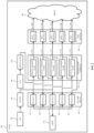
- FIG. 2 is a block diagram of a NAND die 200 according to an example. Although a NAND die 200 is specifically shown and described, the various features disclosed herein may be implemented in and/or by any volatile or non-volatile computer memory chip and/or memory die.
- the voltage input/output pad 210 may be electrically coupled to an on-chip relay 260 that includes a number of switches.
- the on-chip relay 260 includes five switches: switch 1 261 , switch 2 262 , switch 3 263 , switch 4 264 , and switch 5 265 . Although five switches are shown and described, the on-chip relay 260 of the NAND die 200 may include any number of switches.
- Each switch of the on-chip relay 260 is electrically coupled to one or more stages of a charge pump of a charge pump complex 270 .
- the switches enable a voltage to be provided as an input to the various charge pump stages of the charge pump complex 270 . Additionally, the switches enable the various stages of the charge pump to generate and provide a voltage to an external source (e.g., a failing memory die) during a die-to-die voltage sharing process.
- an external source e.g., a failing memory die
- the NAND die 200 also includes a power input (e.g., VCC) 240 and an associated regulator 250 .
- the power input 240 and its associated regulator 250 may generate and/or cause the NAND die 200 to generate an initial internal voltage. Once the initial internal voltage is generated, the voltage is provided to the stage 1 charge pump 271 of the charge pump complex 270 .
- each stage of the charge pump complex 270 is connected in series.
- the output of the stage 1 charge pump 271 is connected to the input of the stage 2 charge pump 272 .
- the output of the stage 2 charge pump 272 is connected to an input of the stage 3 charge pump 273 and so on.
- Each stage of the charge pump complex 270 is configured to increase a received voltage by a determined amount until a target voltage (e.g., a voltage requested or otherwise required to complete a downstream memory operation) is reached or is otherwise available.
- the voltage may be provided to an array 290 of the NAND die (or other downstream circuits) such that a memory operation (e.g., a read operation, a write operation, an erase operation) may be performed.
- a memory operation e.g., a read operation, a write operation, an erase operation
- the controller may cause the stage 2 charge pump 272 of the charge pump complex 270 to provide the voltage to the input of the stage 3 charge pump 273 of the charge pump complex 270 to increase the voltage. This may repeat until the desired voltage is available.
- the NAND die 200 may also include a regulator and switch complex 280 that includes a number of regulators and switches.
- Each regulator and switch of the regulator and switch complex 280 may be electrically coupled to an output of a respective stage of the charge pump complex 270 .
- the output of the stage 1 charge pump 271 of the charge pump complex 270 may be electrically coupled to a regulator and switch 1 281 of the regulator and switch complex 280 ;
- the output of the stage 2 charge pump 272 of the charge pump complex 270 may be electrically coupled to a regulator and switch 2 282 of the regulator and switch complex 280 ;
- the output of the stage 3 charge pump 273 of the charge pump complex 270 may be electrically coupled to a regulator and switch 3 283 of the regulator and switch complex 280 ;
- the output of the stage 4 charge pump 274 of the charge pump complex 270 may be electrically coupled to a regulator and switch 4 284 of the regulator and switch complex 280 ;
- the output of the stage 5 charge pump 275 of the charge pump complex 270
- the NAND die 200 of the present application enables die-to-die voltage sharing between a functional memory die and the failing memory die.
- the die-to-die voltage sharing process may be used to recover data from the failed NAND die and/or may be used to restore functionality to the failed NAND die.
- FIG. 3 A illustrates a functional NAND die 300 generating a voltage for a failing NAND die (e.g., failing NAND die 400 ( FIG. 4 A )) according to an example.
- the functional NAND die 300 may be similar to the NAND die 200 shown and described with respect to FIG. 2 . As such, the reference numbers for the circuitry of the functional NAND die 300 remain consistent with the reference numbers of the circuitry of the NAND die 200 for purposes of clarity.
- a controller e.g., controller 130 ( FIG. 1 ) or other processing circuitry may detect or otherwise determine that a particular NAND die in a data storage device (e.g., data storage device 120 ( FIG. 1 )) is failing or has failed. Detection of a failing memory die will be described in more detail below with respect to FIG. 7 .
- the controller determines or otherwise identifies that the functional NAND die 300 is electrically coupled to the failing NAND die. As such, the controller may determine that the functional NAND die 300 may supply a required voltage to the failing NAND die so the failing NAND die may remain functional—at least until data stored by the failing NAND die is recovered.
- the controller may also determine a voltage (represented as generated voltage 320 ) that is needed to enable the failing NAND die to complete a memory operation and/or to continue functioning.
- a voltage represented as generated voltage 320
- the controller determines that the failing NAND die requires a high voltage (e.g., thirty or more volts).
- the controller instructs the functional NAND die 300 enter a voltage output mode and generate a high voltage (e.g., generated voltage 320 ) to the failing NAND die.
- the power input 240 of the functional NAND die 300 provides a first voltage, via the regulator 250 , to an input of the stage 1 charge pump 271 of the charge pump complex 270 .
- the voltage is subsequently passed to an input of the stage 2 charge pump 272 , an input of the stage 3 charge pump 273 , an input of the stage 4 charge pump 274 , and an input to the stage 5 charge pump 275 of the charge pump complex 270 .
- the voltage increases.
- Switch 5 265 of the on-chip relay 260 of the functional NAND die 300 is activated. Since switch 5 265 is connected to the output of the stage 5 charge pump 275 of the charge pump complex 270 , the generated voltage may be provided (represented by the arrow 310 ) to the input/output pad 210 of the functional NAND die 300 .
- the input/output pad 210 of the functional NAND die 300 may be electrically coupled (e.g., via a bond wire) to an input/output pad and/or a voltage input pad of the failing NAND die.
- the generated voltage 320 may be provided to, and accepted by, the failing NAND die.
- some of the circuitry of the functional NAND die 300 may be in an inactive state when the voltage is generated and subsequently provided to the failing NAND die. For example, switch 1 261 through switch 4 264 may not need to be activated in order to generate and provide the requested voltage. Additionally, since the functional NAND die 300 is operating in a voltage output mode, the generated voltage will not be utilized by the functional NAND die 300 . As such, the regulators and switches of the regulator and switch complex 280 may also be in an inactive state.
- FIG. 3 B illustrates the functional NAND die 300 of FIG. 3 A generating a different (e.g., lower) voltage (represented as generated voltage 330 ) for a failing NAND die (e.g., failing NAND die 400 ( FIG. 4 A )) according to an example.
- a different (e.g., lower) voltage represented as generated voltage 330
- a failing NAND die e.g., failing NAND die 400 ( FIG. 4 A )
- the controller may determine that the failing NAND die requires twelve volts to complete a memory operation or to otherwise remain functional. As such, the controller may cause the functional NAND die 300 to enter the voltage output mode and activate the stage 1 charge pump 271 , the stage 2 charge pump 272 and the stage 3 charge pump 273 of the charge pump complex 270 in order to generate twelve volts. Based on the voltage being generated, switch 3 263 (that is electrically coupled to the output of the stage 3 charge pump 273 of the charge pump complex 270 ) is activated. The generated voltage 330 is then provided (represented by the arrow 310 ) to the input/output pad 210 of the functional NAND die 300 . The generated voltage 330 may then be provided to an input/output pad and/or a voltage input pad of the failing NAND die such as described herein.
- the controller may request that the generated voltage be elevated.
- Voltage elevation may be used to overcome various switches in the paths between the circuitry of the functional NAND die 300 and/or the failed NAND die.
- the switches may be transistors that cause voltage drops.
- the controller may determine or otherwise calculate the voltage drop and instruct the functional NAND die 300 to generate a voltage that takes the voltage drops into account.
- FIG. 4 A illustrates a failing (or failed) NAND die 400 that receives a generated voltage 320 from a functional NAND die (e.g., functional NAND die 300 ( FIG. 3 A )) according to an example.
- the failing NAND die 400 may be similar to the NAND die 200 shown and described with respect to FIG. 2 . As such, the reference numbers for the circuitry of the failing NAND die 400 remain consistent with the reference numbers of the circuitry of the NAND die 200 for purposes of clarity.
- the failing NAND die 400 receives a generated voltage 320 from the functional NAND die 300 ( FIG. 3 A ).
- the voltage input/output pad 210 of the failing NAND die 400 is electrically coupled (e.g., via a bond wire) with the voltage input/output pad 210 of the functional NAND die 300 .
- the generated voltage 320 is taken as an input to the voltage input/output pad 210 of the failing NAND 400 die (represented by the arrow 410 ).
- a controller e.g., controller 130 ( FIG. 1 ) associated or otherwise in communication with the failing NAND die 400 causes the failing NAND die 400 to enter a voltage acceptance mode or otherwise causes the failing NAND die 400 to accept the generated voltage 320 from the functional NAND die 300 .
- the memory operation may be a read operation in order to recover data that is stored in the array 290 . Once the data is read, the data may be provided to and/or stored on another NAND die. Although a read operation is specifically mentioned, the generated voltage 320 may be used to perform other memory operations and/or commands.
- the controller may cause the failing NAND die 400 to enter a voltage acceptance mode. While in this mode, the failing NAND die 400 expects to receive an external voltage. As such, various stages of the charge pump complex 270 of the failing NAND die 400 may not be activated or otherwise used to generate an internal voltage. Likewise, unused and/or unneeded switches on the on-chip relay 260 and/or the regulator and switch complex 280 may also remain in an inactive state.
- the failing NAND die 400 may use its own circuitry to generate an internal voltage to supplement a received voltage.
- the controller and/or the failing NAND die 400 may need to determine or otherwise identify which charge pumps in the charge pump complex 270 of the failing NAND die 400 are functional. Determining the functionality of the charge pumps in a charge pump complex 270 is described in greater detail below with respect to FIG. 7 .
- FIG. 4 B illustrates how a failing NAND die 400 may supplement a received voltage by generating an internal voltage using its own circuitry according to an example.
- the failing NAND die 400 may receive a generated voltage 330 from the functional NAND die 300 via a bond wire or other electrical connection such as described above.
- the generated voltage 330 is lower than is needed to perform a memory operation.
- the memory operation to be performed on the failing NAND die 400 may require thirty (or more) volts.
- the failing NAND die 400 receives the generated voltage 330 (e.g., via its voltage input/output pad 210 ) and causes activation of switch 3 263 .
- Switch 3 263 provides the generated voltage 330 as an input to the stage 4 charge pump 274 of the charge pump complex 270 .
- the stage 4 charge pump 274 increases the voltage of the generated voltage 330 .
- the increased voltage is then provided to an input of the stage 5 charge pump 275 of the charge pump complex 270 .
- the voltage is increased again and subsequently provided to the regulator and switch 5 285 of the regulator and switch complex 280 .
- the charge pumps of the failing NAND die 400 increased the generated voltage 330 from the received voltage to the needed thirty (or more volts). The voltage may then be used to perform a memory operation on the array 290 and/or may be provided to other downstream circuitry.
- FIG. 6 B illustrates a bond wire (represented by the arrow 620 ) or other coupling mechanism electrically coupling a voltage input/output pad of a functional NAND die (e.g., functional NAND die 300 ( FIG. 3 B )) to a voltage input/output pad of the failing NAND die (e.g., failing NAND die 400 ( FIG. 4 B )).
- a voltage generated by the stage 1 charge pump, the stage 2 charge pump and the stage 3 charge pump of the pump complex of the functional NAND die 300 may be provided as an input to the voltage input/output pad of the failing NAND die 400 .
- the voltage is provided from the functional NAND die 300 to the failing NAND die 400 in response to a defect detected in a charge pump (e.g., the stage 4 charge pump) of the failing NAND die 400 .
- a charge pump e.g., the stage 4 charge pump
- the switch 5 from the on-chip relay of the failing NAND die 400 may be activated and provide the received voltage to a regulator and switch 5 of a regulator and switch complex of the failing NAND die 400 .
- the voltage may then be provided to the array so as to enable a memory operation to be performed such as previously described.
- FIG. 6 D illustrates a bond wire (represented by the arrow 640 ) or other coupling mechanism electrically coupling a voltage input/output pad of a functional NAND die (e.g., functional NAND die 300 ( FIG. 3 A )) to a voltage input/output pad of a failing NAND die (e.g., failing NAND die 400 ( FIG. 4 A )) while still allowing the failing NAND die to supplement the received voltage according to an example.
- a voltage generated by the stage 1 charge pump through the stage 5 charge pump of the pump complex of the functional NAND die 300 may be provided as an input to the voltage input/output pad of the failing NAND die 400 .
- any number of charge pumps on a functional NAND die may be used to generate a voltage for a failing NAND die.
- the voltage input pad and/or the voltage input/output pad of a functional NAND die may be electrically coupled to the voltage input pad and/or the voltage input/output pad of the failing NAND die.
- a voltage input pad may function in a similar manner to the voltage input/output pad.
- a voltage range of any ESD structures, as well as any associated transistors, may need to be adjusted.
- the stage X+1 charge pump of the second NAND die Upon receipt of the generated voltage, the stage X+1 charge pump of the second NAND die increases the voltage and attempts to perform an operation (e.g., a memory operation). The status and/or the outcome of the operation is monitored ( 730 ) so a determination ( 740 ) may be made as to whether the operation was successfully completed.
- an operation e.g., a memory operation
- the controller When the external voltage has been provided to the NAND die, the controller causes the NAND die to repeat ( 940 ) the requested operation (e.g., repeat the failed operation) using the external voltage.
- the controller monitors the operation to determine ( 950 ) whether the operation was successful with the external voltage. If it is determined that the operation was successful, the controller flags ( 970 ) or otherwise identifies the NAND die as having a particular voltage issue. If it is determined ( 950 ) that the operation was not successful, the controller may flag the NAND die as inoperable. In another example, the controller may cause an additional external voltage to be provided to the NAND die prior to flagging the NAND die as inoperable.
- a first NAND die supplies a voltage to a second NAND die and the second NAND die supplies voltage to the first NAND die.
- a voltage input/output pad (e.g., VMON) of NAND 2 1120 may be electrically coupled (e.g., via a bond wire) to a voltage input pad (e.g., VPP) of NAND 1 1110 .
- a voltage input/output pad of NAND 1 may be electrically coupled to a voltage input pad of NAND 2 1120 .
- NAND 3 1130 and NAND 4 1140 In this arrangement, one NAND die may be available as a voltage source for a failed NAND die.
- capacitors that are external to a NAND die are prone to failure. If a capacitor were to fail, the failure would only be detected when power is actually lost. This could have a lot of system-level consequences. For example, multiple drives may power off at the same time. Accordingly, the capacitors may need to be tested while running. The tests may involve checking the current draw and/or a voltage drop and determining whether capacitance is within some valid range.
- a switch or firmware may be used to disable or otherwise prevent the NAND die from relying (at least partially) on system-level power (e.g., power provided by a voltage rail). Accordingly, a fault determination may be executed by causing the NAND die to perform a memory operation when the voltage input/output pad is configured to accept a system-level power supply such as described above with respect to FIG. 9 . If the NAND die is successful in performing the memory operation using the external power supply (and presuming the NAND die was unsuccessful in performing the operation when the switch was open), the NAND die may be identified as faulty.
- Computer-readable media may include computer storage media.
- Computer storage media may include volatile and nonvolatile, removable and non-removable media implemented in any method or technology for storage of information, such as computer readable instructions, data structures, or program modules.
- Computer storage media may include RAM, ROM, electrically erasable read-only memory (EEPROM), flash memory or other memory technology, CD-ROM, digital versatile disks (DVD) or other optical storage, magnetic cassettes, magnetic tape, magnetic disk storage or other magnetic storage devices, or any other article of manufacture which can be used to store information and which can be accessed by a computing device (e.g., computing device 110 ( FIG. 1 )). Any such computer storage media may be part of the computing device.
- Computer storage media does not include a carrier wave or other propagated or modulated data signal.
- references to an element herein using a designation such as “first,” “second,” and so forth does not generally limit the quantity or order of those elements. Rather, these designations may be used as a method of distinguishing between two or more elements or instances of an element. Thus, reference to first and second elements does not mean that only two elements may be used or that the first element precedes the second element. Additionally, unless otherwise stated, a set of elements may include one or more elements.
Landscapes
- Engineering & Computer Science (AREA)
- Power Engineering (AREA)
- Microelectronics & Electronic Packaging (AREA)
- Read Only Memory (AREA)
Abstract
Description
Claims (20)
Priority Applications (1)
| Application Number | Priority Date | Filing Date | Title |
|---|---|---|---|
| US17/592,237 US11776637B2 (en) | 2022-02-03 | 2022-02-03 | Voltage sharing across memory dies in response to a charge pump failure |
Applications Claiming Priority (1)
| Application Number | Priority Date | Filing Date | Title |
|---|---|---|---|
| US17/592,237 US11776637B2 (en) | 2022-02-03 | 2022-02-03 | Voltage sharing across memory dies in response to a charge pump failure |
Publications (2)
| Publication Number | Publication Date |
|---|---|
| US20230245705A1 US20230245705A1 (en) | 2023-08-03 |
| US11776637B2 true US11776637B2 (en) | 2023-10-03 |
Family
ID=87432455
Family Applications (1)
| Application Number | Title | Priority Date | Filing Date |
|---|---|---|---|
| US17/592,237 Active 2042-06-24 US11776637B2 (en) | 2022-02-03 | 2022-02-03 | Voltage sharing across memory dies in response to a charge pump failure |
Country Status (1)
| Country | Link |
|---|---|
| US (1) | US11776637B2 (en) |
Citations (7)
| Publication number | Priority date | Publication date | Assignee | Title |
|---|---|---|---|---|
| US20030065994A1 (en) * | 1999-06-22 | 2003-04-03 | Samsung Electronics Co., Ltd. | Semiconductor device with malfunction control circuit and controlling method thereof |
| US7085152B2 (en) | 2003-12-29 | 2006-08-01 | Intel Corporation | Memory system segmented power supply and control |
| US20070263442A1 (en) | 2006-05-15 | 2007-11-15 | Apple Inc. | Off-Die Charge Pump that Supplies Multiple Flash Devices |
| US20120105037A1 (en) * | 2007-04-30 | 2012-05-03 | Chih-Jen Yen | Voltage Conversion Device Capable of Enhancing Conversion Efficiency |
| US20140284674A1 (en) * | 2013-03-22 | 2014-09-25 | Kabushiki Kaisha Toshiba | Semiconductor storage device capable of relieving capacitor defect |
| US20150177995A1 (en) * | 2013-12-24 | 2015-06-25 | International Business Machines Corporation | Extending useful life of a non-volatile memory by health grading |
| US20210082879A1 (en) * | 2019-09-18 | 2021-03-18 | Kioxia Corporation | Semiconductor memory device |
-
2022
- 2022-02-03 US US17/592,237 patent/US11776637B2/en active Active
Patent Citations (7)
| Publication number | Priority date | Publication date | Assignee | Title |
|---|---|---|---|---|
| US20030065994A1 (en) * | 1999-06-22 | 2003-04-03 | Samsung Electronics Co., Ltd. | Semiconductor device with malfunction control circuit and controlling method thereof |
| US7085152B2 (en) | 2003-12-29 | 2006-08-01 | Intel Corporation | Memory system segmented power supply and control |
| US20070263442A1 (en) | 2006-05-15 | 2007-11-15 | Apple Inc. | Off-Die Charge Pump that Supplies Multiple Flash Devices |
| US20120105037A1 (en) * | 2007-04-30 | 2012-05-03 | Chih-Jen Yen | Voltage Conversion Device Capable of Enhancing Conversion Efficiency |
| US20140284674A1 (en) * | 2013-03-22 | 2014-09-25 | Kabushiki Kaisha Toshiba | Semiconductor storage device capable of relieving capacitor defect |
| US20150177995A1 (en) * | 2013-12-24 | 2015-06-25 | International Business Machines Corporation | Extending useful life of a non-volatile memory by health grading |
| US20210082879A1 (en) * | 2019-09-18 | 2021-03-18 | Kioxia Corporation | Semiconductor memory device |
Also Published As
| Publication number | Publication date |
|---|---|
| US20230245705A1 (en) | 2023-08-03 |
Similar Documents
| Publication | Publication Date | Title |
|---|---|---|
| US9224503B2 (en) | Memory test with in-line error correction code logic | |
| US8093868B2 (en) | In situ verification of capacitive power support | |
| CN110729704B (en) | Power supply device, control method of power supply circuit, and storage device | |
| US8867287B2 (en) | Test circuit and method of semiconductor memory apparatus | |
| US20090164846A1 (en) | Fault Injection In Dynamic Random Access Memory Modules For Performing Built-In Self-Tests | |
| US9728276B2 (en) | Integrated circuits with built-in self test mechanism | |
| US20150121133A1 (en) | Protocol checking logic circuit for memory system reliability | |
| US20200142795A1 (en) | Semiconductor device, semiconductor systems and test-control methods | |
| CN113366576B (en) | System, memory system and method for retention self-test on memory system | |
| US7401270B2 (en) | Repair of semiconductor memory device via external command | |
| CN104101798A (en) | Method for detecting or predicting an electrical fault | |
| US20210034131A1 (en) | Actual or apparent power failure detecting system and method | |
| US11776637B2 (en) | Voltage sharing across memory dies in response to a charge pump failure | |
| CN109979519B (en) | Verification method of memory integrity, non-volatile memory and electronic device | |
| US20200066367A1 (en) | Memory device controller | |
| US11068369B2 (en) | Computer device and testing method for basic input/output system | |
| US10037787B2 (en) | Circuit for outputting information of a memory circuit during a self-refresh mode and related method thereof | |
| US10718819B2 (en) | Power module health test | |
| US4800532A (en) | Circuit arrangement with a processor and at least two read-write memories | |
| US10852801B2 (en) | Determine a failure event of a power supply | |
| CN108009054A (en) | A kind of double eMMC backup storage systems and method | |
| CN109215724B (en) | Method and device for automatically detecting and repairing memory | |
| KR100998597B1 (en) | Wafer Test System and Method for Spare Cell Analysis | |
| US20140351620A1 (en) | Power supply detecting system and detecting method | |
| CN118394582A (en) | Power failure memory detection circuit and server |
Legal Events
| Date | Code | Title | Description |
|---|---|---|---|
| AS | Assignment |
Owner name: WESTERN DIGITAL TECHNOLOGIES, INC., CALIFORNIA Free format text: ASSIGNMENT OF ASSIGNORS INTEREST;ASSIGNORS:RILL, ELLIOTT;LINNEN, DANIEL;PERIYANNAN, KIRUBAKARAN;SIGNING DATES FROM 20220127 TO 20220131;REEL/FRAME:058881/0990 |
|
| FEPP | Fee payment procedure |
Free format text: ENTITY STATUS SET TO UNDISCOUNTED (ORIGINAL EVENT CODE: BIG.); ENTITY STATUS OF PATENT OWNER: LARGE ENTITY |
|
| STPP | Information on status: patent application and granting procedure in general |
Free format text: NOTICE OF ALLOWANCE MAILED -- APPLICATION RECEIVED IN OFFICE OF PUBLICATIONS |
|
| AS | Assignment |
Owner name: JPMORGAN CHASE BANK, N.A., ILLINOIS Free format text: PATENT COLLATERAL AGREEMENT - A&R LOAN AGREEMENT;ASSIGNOR:WESTERN DIGITAL TECHNOLOGIES, INC.;REEL/FRAME:064715/0001 Effective date: 20230818 Owner name: JPMORGAN CHASE BANK, N.A., ILLINOIS Free format text: PATENT COLLATERAL AGREEMENT - DDTL LOAN AGREEMENT;ASSIGNOR:WESTERN DIGITAL TECHNOLOGIES, INC.;REEL/FRAME:067045/0156 Effective date: 20230818 |
|
| STPP | Information on status: patent application and granting procedure in general |
Free format text: PUBLICATIONS -- ISSUE FEE PAYMENT RECEIVED |
|
| STPP | Information on status: patent application and granting procedure in general |
Free format text: PUBLICATIONS -- ISSUE FEE PAYMENT VERIFIED |
|
| STCF | Information on status: patent grant |
Free format text: PATENTED CASE |
|
| AS | Assignment |
Owner name: SANDISK TECHNOLOGIES, INC., CALIFORNIA Free format text: ASSIGNMENT OF ASSIGNORS INTEREST;ASSIGNOR:WESTERN DIGITAL TECHNOLOGIES, INC.;REEL/FRAME:067567/0682 Effective date: 20240503 Owner name: SANDISK TECHNOLOGIES, INC., CALIFORNIA Free format text: ASSIGNMENT OF ASSIGNOR'S INTEREST;ASSIGNOR:WESTERN DIGITAL TECHNOLOGIES, INC.;REEL/FRAME:067567/0682 Effective date: 20240503 |
|
| AS | Assignment |
Owner name: SANDISK TECHNOLOGIES, INC., CALIFORNIA Free format text: CHANGE OF NAME;ASSIGNOR:SANDISK TECHNOLOGIES, INC.;REEL/FRAME:067982/0032 Effective date: 20240621 |
|
| AS | Assignment |
Owner name: JPMORGAN CHASE BANK, N.A., AS THE AGENT, ILLINOIS Free format text: PATENT COLLATERAL AGREEMENT;ASSIGNOR:SANDISK TECHNOLOGIES, INC.;REEL/FRAME:068762/0494 Effective date: 20240820 |
|
| AS | Assignment |
Owner name: SANDISK TECHNOLOGIES, INC., CALIFORNIA Free format text: PARTIAL RELEASE OF SECURITY INTERESTS;ASSIGNOR:JPMORGAN CHASE BANK, N.A., AS AGENT;REEL/FRAME:071382/0001 Effective date: 20250424 Owner name: JPMORGAN CHASE BANK, N.A., AS COLLATERAL AGENT, ILLINOIS Free format text: SECURITY AGREEMENT;ASSIGNOR:SANDISK TECHNOLOGIES, INC.;REEL/FRAME:071050/0001 Effective date: 20250424 |