CROSS-REFERENCE TO RELATED APPLICATION
This application claims the priority benefit of Taiwan application serial no. 110135493, filed on Sep. 24, 2021. The entirety of the above-mentioned patent application is hereby incorporated by reference herein and made a part of this specification.
BACKGROUND
Technical Field
The disclosure relates to a pick-and-place mechanism, and in particular to a pick-and-place mechanism for a stylus.
Description of Related Art
With the development of touch display technology, touch display screens have been widely applied in smart phones, tablet computers, notebook computers, or other electronic devices. In order to improve the touch accuracy of the user operating the touch display screen and assist in the execution of precise drawing and writing actions, the stylus has been proposed. In addition, in order to improve the convenience of carrying the stylus and avoid losing the stylus, most of the smart phones, tablet computers, notebook computers, or other electronic devices are provided with slots for the user to retrieve or store the stylus.
Generally speaking, during the process of retrieving the stylus, the user must grasp the tail end of the stylus exposed from the slot with his fingers, and then pull out the stylus by force, so the operation is neither convenient nor smooth. Alternatively, the stylus can be smoothly removed from the housing of the electronic device by the user performing repeated pressing actions. The former obviously reduces the degree of operation, while the latter obviously has the possibility of mistouch.
SUMMARY
The disclosure provides a pick-and-place mechanism for a stylus, which is applicable for a portable electronic device, and improves the convenience of the user during picking and placing through an electrical control manner to effectively prevent the occurrence of mistouch.
A pick-and-place mechanism for a stylus of the disclosure is applicable for a portable electronic device. The portable electronic device has a housing. The pick-and-place mechanism for the stylus includes a moving member, a latch assembly, and a switch element. The moving member is movably disposed in the housing. The stylus is adapted to be inserted into the housing and locked with the moving member to move synchronously. The latch assembly is disposed in the housing and switches between a lock state and an unlock state. In the lock state, the latch assembly locks the stylus in the housing. In the unlock state, the latch assembly moves at least part of the stylus out of the housing. The switch element is electrically connected to the latch assembly to drive the latch assembly to switch between the lock state and the unlock state.
Based on the above, in the pick-and-place mechanism, the switch element is electrically connected to the latch assembly, so that the user can control the latch assembly through the switch element to be switched between the lock state and the unlock state. Accordingly, the user can perform corresponding operations according to usage requirements. When in the lock state, the stylus can be submerged in the housing to achieve the required immediacy and protection, and prevent the stylus from falling out of the housing when not required due to mistouching by the user. Correspondingly, in the unlock state, the user uses the switch element to drive the latch assembly to move at least part of the stylus out of the housing, so that the user can smoothly hold and take out the stylus without being interfered by the surrounding structure of the housing, thereby enabling the processes of picking and placing to be convenient.
BRIEF DESCRIPTION OF THE DRAWINGS
FIG. 1 is a schematic view of a portable electronic device according to an embodiment of the disclosure.
FIG. 2 is a schematic view of a pick-and-place mechanism according to an embodiment of the disclosure.
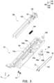
FIG. 3 is an exploded view of the pick-and-place mechanism of FIG. 2 .
FIG. 4A to FIG. 4E illustrate a pick-and-place process of the stylus with partial enlarged views.
FIG. 5 is a schematic view of a driving member according to another embodiment of the disclosure.
FIG. 6 is an exploded view of a pick-and-place mechanism according to another embodiment of the disclosure.
FIG. 7 is a partial enlarged view of the pick-and-place mechanism of FIG. 6 when accommodating a stylus.
FIG. 8A and FIG. 8B illustrate a pick-and-place process of the stylus with partial enlarged views.
DETAILED DESCRIPTION OF DISCLOSED EMBODIMENTS
FIG. 1 is a schematic view of a portable electronic device according to an embodiment of the disclosure. FIG. 2 is a schematic view of a pick-and-place mechanism according to an embodiment of the disclosure. FIG. 3 is an exploded view of the pick-and-place mechanism of FIG. 2 . Cartesian coordinates XYZ are provided here to facilitate description of components. Please refer to FIG. 1 to FIG. 3 at the same time. In the embodiment, the pick-and-place mechanism for a stylus (hereinafter referred to as a pick-and-place mechanism PM) is applicable for a portable electronic device 100, which is exemplified as a notebook computer here, but not limited thereto. The portable electronic device 100 has a housing 110, and the inside of the housing 110 has a base 111 to serve as a setting reference for a storage space of a stylus 200 and relevant mechanisms. The pick-and-place mechanism PM includes a moving member 120, a latch assembly 140, and a switch element 130. The moving member 120 is movably disposed on the base 111 in the housing 110. The stylus 200 is adapted to be inserted into the housing 110 and locked with the moving member 120, so that the stylus 200 and the moving member 120 move synchronously on the base 111. The latch assembly 140 is disposed in the housing 110 and switches between a lock state and an unlock state. In the lock state, the latch assembly 140 locks the stylus 200 in the housing 110. In the unlock state, the latch assembly 140 moves at least part of the stylus 200 out of the housing 110 (may refer to FIG. 1 ). The switch element 130 is electrically connected to the latch assembly 140 to drive the latch assembly 140 to switch between the lock state and the unlock state.
In detail, please refer to FIG. 2 and FIG. 3 again. The moving member 120 is movably coupled to a track 111 a of the base 111. A front wall of the moving member 120 moves on the track 111 a along an X-axis and abuts against an inner wall of the base 111 through an elastic member 144. The moving element 120 has a baffle 122 extending toward a negative Y-axis direction, and the switch element 130 is disposed on the base 111 and is located on a moving path of the baffle 122. The moving member 120 also has a hook 121 adjacent to the baffle 122, so that the stylus 200 may be locked by the hook 121 after being moved into the housing 110. The hook 121 locks at a circular recess 210 (as shown in FIG. 2 ) of the stylus 200.
Furthermore, the latch assembly 140 of the embodiment includes an engaging member LT, a power supply element 145, a memory alloy wire 143, and the elastic member 144. The engaging member LT is movably disposed in the housing 110 and is located on the moving path of the moving member 120. The power supply element 145 is disposed in the housing 110 and is electrically connected to the switch element 130. One end E2 of the memory alloy wire 143 is connected to the engaging member LT, other end E1 thereof is fixed to the base 111 of the housing 110 through a locking member P1, and the memory alloy wire 143 can be further electrically connected to the power supply element 145. Accordingly, the memory alloy wire 143 is energized due to the switch element 130 activating the power supply element 145, so as to be heated to change the length, and the change in length can drive the engaging member LT to be locked with the moving member 120 to reach the lock state or move the engaging member LT away from the moving member 120 to reach the unlock state.
Furthermore, the engaging member LT of the embodiment includes an elastic arm 141 and a driving unit 142. The driving unit 142 is pivoted to a pivot hole 111 b of the base 111 through a shaft portion 142 c thereof, and the driving unit 142 has an L-shaped structure and two driving ends 142 a and 142 b. The driving end 142 b is connected to the memory alloy wire 143. Here, the memory alloy wire 143 is exemplified as being sleeved onto the driving end 142 b with a necked structure. The driving end 142 a passes through a recess 141 b of the elastic arm 141 and abuts against the elastic arm 141 in structure. In this way, the driving unit 142 can rotate relative to the base 111 along a Z-axis, so that the driving end 142 a thereof can drive the elastic arm 141. It should be noted that the materials of the housing 110 and the base 111 of the embodiment are, for example, plastic. Therefore, the cantilever structure (that is, the elastic arm 141) extended from the base 111 has considerable elasticity to enable the deformation thereof to be reflected on the movement of an end hook 141 a. Accordingly, when the length of the memory alloy wire 143 is changed, for example, when the length is shortened, the memory alloy wire 143 can pull the driving end 142 b to rotate the driving unit 142, thereby enabling the driving end 142 a to drive the end hook 141 a of the elastic arm 141 to move into or out of a lock hole 123 of the moving member 120.
FIG. 4A to FIG. 4E illustrate a pick-and-place process of the stylus with partial enlarged views. Please refer to FIG. 4A to FIG. 4C, which illustrate the relevant steps when the stylus 200 is moved into the housing 110. In FIG. 4A, the moving member 120 is pushed by the elastic member 144 away from the inner wall of the base 111, so that the end hook 141 a of the elastic arm 141 that has not yet fallen into the lock hole 123 is in a deformed state due to the interference of the moving member 120. Then, as shown in FIG. 4B, when the stylus 200 is continuously moved in (the user continues to apply force to move the stylus 200 into the housing 110), the circular recess 210 of the stylus 200 is locked by the hook 121 of the moving member 120, so that the moving member 120 can move toward a positive X-axis direction synchronously with the stylus 200.
In FIG. 4C, the stylus 200 and the moving member 120 continue to move synchronously toward the positive X-axis direction until the stylus 200 and the moving member 120 reach the bottom, that is, the front wall of the moving member 120 substantially abuts against the inner wall of the base 111 (both are located on the left side in FIG. 4C. At this time, the baffle 122 of the moving element 120 is abutting against and triggering the switch element 130. More importantly, at this time, the end hook 141 a of the elastic arm 141 is not blocked by the moving member 120 in structure and can fall into the lock hole 123 of the moving member 120, and the elastic member 144 is pressed between the inner wall of the base 111 and the front wall of the moving member 120, so as to be deformed to accumulate an elastic force F1.
Next, please refer to FIG. 4D. The user releases the pushing force of moving the stylus 200 into the housing 110, so the elastic force F1 accumulated by the elastic member 144 drives the moving member 120 to move toward a negative X-axis direction. However, since the end hook 141 a of the elastic arm 141 has fallen into the lock hole 123, the moving member 120 interferes with the elastic arm 141 along the X-axis, so that the moving member 120 and the stylus 200 thereon are maintained in the position shown in FIG. 4D, which is the lock state of the latch assembly 140.
Finally, please refer to FIG. 4E. When the stylus 200 is to be taken out of the housing 110, the user only needs to press the switch element 130 again, that is, press the stylus 200 again, so that the stylus 200 and the moving member 120 move synchronously to the position shown in FIG. 4C again, that is, let the moving member 120 pass through the baffle 122 and trigger the switch element 130 again, so that the switch element 130 may energize and heat the memory alloy wire 143 through the power supply element 145. In this way, the length of the memory alloy wire 143 is changed (for example, shortened) due to energization and heating, thereby generating a tensile force F2 to further drive (rotate) the driving unit 142, so that the driving end 142 a of the driving unit 142 drives the elastic arm 141 to deform, and the end hook 141 a is moved away from the lock hole 123, as shown in FIG. 4E, which is the unlock state of the latch assembly 140 (the interference between the elastic arm 141 and the moving member 120 along the X-axis has been released). Therefore, the moving member 120 and the stylus 200 thereon can be driven by the elastic force of the elastic member 144 to continue to move toward the negative X-axis direction, so that at least part of the stylus 200 is moved out of the housing 110, which may refer to the state shown in FIG. 1 . Therefore, that the user can smoothly hold and pick up the stylus 200.
It should be noted that persons skilled in the art can set the timing of triggering the switch element 130 by a control chip or relevant control electronic elements (not shown) to comply with the timing of the action of energizing and heating the memory alloy wire 143 in FIG. 4A to FIG. 4E.
FIG. 5 is a schematic view of a driving member according to another embodiment of the disclosure. Different from the engaging member LT, which is composed of the elastic arm 141 and the driving unit 142, referring to FIG. 5 , an engaging member 342 of the embodiment consolidates the component features of the above embodiment on a single structure. As shown in FIG. 5 , in addition to having the same driving ends 142 a and 142 b and shaft portion 142 c as the driving unit 142, the engaging member 342 of the embodiment also has a hook 342 a at the end, which can generate the same effect as the end hook 141 a of the elastic arm 141, that is, to move in or move out the lock hole 123 of the moving member 120 to generate the required lock state and unlock state.
FIG. 6 is an exploded view of a pick-and-place mechanism according to another embodiment of the disclosure. FIG. 7 is a partial enlarged view of the pick-and-place mechanism of FIG. 6 when accommodating a stylus. Please refer to FIG. 6 and FIG. 7 at the same time. In the embodiment, a pick-and-place mechanism PM2 includes a moving member 420, a latch assembly 440, and a switch element 430, the relative relationship thereof is the same as the above embodiment, and the stylus 200 is adapted to enter and exit a base 411 through an entrance 411 a of the base 411. The difference is that the latch assembly 440 of the embodiment includes a magnetic conductive member 441, a magnetic member 442, and an electromagnet module 443. The magnetic conductive member 441 is, for example, made of a material with magnetic conductivity, which is disposed in the housing 110 and is substantially located on an inner wall 411 b of the base 411. The magnetic member 442 is, for example, a permanent magnet, which is disposed on a front wall 422 of the moving member 420, and the moving member 420 is movably disposed on the base 411. As shown in FIG. 6 and FIG. 7 , the base 411 has a pair of arm portions A1 extending from the inner wall 411 b. The moving member 420 disposed on the base 411 enables the arm portions A1 to pass through a pair of recesses A2 beside the front wall 422, so that the two generate a guiding effect with relative sliding. The magnetic conductive member 441 and the magnetic member 442 are both located on the X-axis and are on the moving paths of each other. Therefore, the magnetic member 442 moves along with the moving member 420 and generates magnetic attraction when moving close to the magnetic conductive member 441. FIG. 8A and FIG. 8B illustrate a pick-and-place process of the stylus with partial enlarged views. Please refer to FIG. 6 , FIG. 7 , and FIG. 8A, which show the lock state where the moving member 420 and the magnetic conductive member 441 are moved close to each other to be magnetically attracted.
Next, please refer to FIG. 6 and FIG. 8B. The electromagnet module 443 of the embodiment is disposed on a back side of the inner wall 411 b of the base 411 to back face from the magnetic conductive member 441, so that the magnetic member 442, the magnetic conductive member 441, and the electromagnet module 443 are located on the same straight line (the X-axis), and the magnetic conductive member 441 is located between the magnetic member 442 and the electromagnet module 443. The electromagnet module 443 is electrically connected to the switch element 430, and the electromagnet module 443 substantially includes an electromagnet body (not shown) and a power supply unit (not shown). The power supply unit is electrically connected between the switch element 430 and the electromagnet body. In this way, the user can turn on or off the power supply unit through the switch element 430 to energize or deenergize the electromagnet body. When energizing, the electromagnet module 443 of the embodiment generates a magnetic force, and in particular, generates a magnetic force opposite to the magnetism of the magnetic member 442, that is, generates a magnetic repulsion on the magnetic member 442, and the magnetic repulsion is greater than the magnetic attraction between the magnetic member 442 and the magnetic conductive member 441. At this time, the electromagnet module 443 is equivalent to magnetically attracting the magnetic conductive member 441 and magnetically repelling the magnetic member 442. Accordingly, the magnetic repulsion can drive the moving member 420 and the stylus 200 thereon to cancel the bottoming (lock) state shown in FIG. 8A and switch to the unlock state, that is, the magnetic member 442 and the magnetic conductive member 441 are separated from each other, so that at least part of the stylus 200 is moved out of the housing 110 (may refer to FIG. 1 ).
On the other hand, the moving member 420 of the embodiment is similar to the moving member 120 and has a hook 421 for locking the stylus 200. The moving member 420 also enables the hook 421 to be locked with the circular recess 210 of the stylus 200 when the moving member 420 and the stylus 200 reach the bottom (the magnetic member 442 and the magnetic conductive member 441 are magnetically attracted to each other and are in contact with each other). It is also worth mentioning that the base 411 of the embodiment also has a pushing inclined surface 411 c, which is located on the moving path of the hook 421. The moving member 420 also has a pushing inclined surface 423 formed from the hook 421. Therefore, in the unlock state, as shown in FIG. 8B, the pushing inclined surface 411 c interferes with the hook 421 in structure, and due to the pushing inclined surfaces 411 c and 423 pushing against each other (while the other side of the hook 421 is supported by the arm portion A1), a pair of hooks 421 can be respectively elastically deformed toward the positive and negative Y-axis directions, that is, the pushing inclined surface 411 c of the base 411 stretches the hooks 421 to drive the hooks 421 to move away from the circular recess 210 to release the stylus 200.
In summary, in the embodiments of the disclosure, the pick-and-place mechanism for the stylus is applicable for the portable electronic device. The portable electronic device has the housing. The pick-and-place mechanism for the stylus includes the moving member, the latch assembly, and the switch element. The moving member is movably disposed in the housing. The stylus is adapted to be inserted into the housing and locked with the moving member to move synchronously. The latch assembly is disposed in the housing and switches between the lock state and the unlock state. In the lock state, the latch assembly locks the stylus in the housing. In the unlock state, the latch assembly moves at least part of the stylus out of the housing. The switch element is electrically connected to the latch assembly to drive the latch assembly to switch between the lock state and the unlock state.
In one of the embodiments, the latch assembly provides the lock state to the moving member through the engaging member, so that the user can change the length of the memory alloy wire through the switch element to drive the engaging member, and the engaging member releases the moving member to switch to the unlock state. In another embodiment, the latch assembly enables the moving member and the base to reach the bottom and be magnetically attracted to each other by the magnetic attraction, so that the user can activate an electromagnet through the switch element, thereby destroying the magnetic attraction, so as to release the moving member to form the unlock state.
Regardless of the above embodiments, the disclosure generates the required picking and placing of the stylus through electrical control measures, thereby improving the convenience of the user during operation to prevent the occurrence of mistouch.