US11772032B2 - Filter unit quality management system and filter unit quality management method - Google Patents
Filter unit quality management system and filter unit quality management method Download PDFInfo
- Publication number
- US11772032B2 US11772032B2 US16/962,407 US201916962407A US11772032B2 US 11772032 B2 US11772032 B2 US 11772032B2 US 201916962407 A US201916962407 A US 201916962407A US 11772032 B2 US11772032 B2 US 11772032B2
- Authority
- US
- United States
- Prior art keywords
- filter
- evaluation parameter
- unit
- filters
- quality
- Prior art date
- Legal status (The legal status is an assumption and is not a legal conclusion. Google has not performed a legal analysis and makes no representation as to the accuracy of the status listed.)
- Active, expires
Links
Images


Classifications
-
- B—PERFORMING OPERATIONS; TRANSPORTING
- B01—PHYSICAL OR CHEMICAL PROCESSES OR APPARATUS IN GENERAL
- B01D—SEPARATION
- B01D46/00—Filters or filtering processes specially modified for separating dispersed particles from gases or vapours
- B01D46/0084—Filters or filtering processes specially modified for separating dispersed particles from gases or vapours provided with safety means
- B01D46/0086—Filter condition indicators
-
- B—PERFORMING OPERATIONS; TRANSPORTING
- B01—PHYSICAL OR CHEMICAL PROCESSES OR APPARATUS IN GENERAL
- B01D—SEPARATION
- B01D46/00—Filters or filtering processes specially modified for separating dispersed particles from gases or vapours
- B01D46/56—Filters or filtering processes specially modified for separating dispersed particles from gases or vapours with multiple filtering elements, characterised by their mutual disposition
-
- B—PERFORMING OPERATIONS; TRANSPORTING
- B01—PHYSICAL OR CHEMICAL PROCESSES OR APPARATUS IN GENERAL
- B01D—SEPARATION
- B01D46/00—Filters or filtering processes specially modified for separating dispersed particles from gases or vapours
- B01D46/42—Auxiliary equipment or operation thereof
-
- B—PERFORMING OPERATIONS; TRANSPORTING
- B01—PHYSICAL OR CHEMICAL PROCESSES OR APPARATUS IN GENERAL
- B01D—SEPARATION
- B01D46/00—Filters or filtering processes specially modified for separating dispersed particles from gases or vapours
- B01D46/42—Auxiliary equipment or operation thereof
- B01D46/44—Auxiliary equipment or operation thereof controlling filtration
- B01D46/446—Auxiliary equipment or operation thereof controlling filtration by pressure measuring
-
- B—PERFORMING OPERATIONS; TRANSPORTING
- B01—PHYSICAL OR CHEMICAL PROCESSES OR APPARATUS IN GENERAL
- B01D—SEPARATION
- B01D46/00—Filters or filtering processes specially modified for separating dispersed particles from gases or vapours
- B01D46/42—Auxiliary equipment or operation thereof
- B01D46/44—Auxiliary equipment or operation thereof controlling filtration
- B01D46/46—Auxiliary equipment or operation thereof controlling filtration automatic
-
- F—MECHANICAL ENGINEERING; LIGHTING; HEATING; WEAPONS; BLASTING
- F01—MACHINES OR ENGINES IN GENERAL; ENGINE PLANTS IN GENERAL; STEAM ENGINES
- F01D—NON-POSITIVE DISPLACEMENT MACHINES OR ENGINES, e.g. STEAM TURBINES
- F01D25/00—Component parts, details, or accessories, not provided for in, or of interest apart from, other groups
-
- F—MECHANICAL ENGINEERING; LIGHTING; HEATING; WEAPONS; BLASTING
- F02—COMBUSTION ENGINES; HOT-GAS OR COMBUSTION-PRODUCT ENGINE PLANTS
- F02C—GAS-TURBINE PLANTS; AIR INTAKES FOR JET-PROPULSION PLANTS; CONTROLLING FUEL SUPPLY IN AIR-BREATHING JET-PROPULSION PLANTS
- F02C7/00—Features, components parts, details or accessories, not provided for in, or of interest apart form groups F02C1/00 - F02C6/00; Air intakes for jet-propulsion plants
- F02C7/04—Air intakes for gas-turbine plants or jet-propulsion plants
- F02C7/05—Air intakes for gas-turbine plants or jet-propulsion plants having provisions for obviating the penetration of damaging objects or particles
- F02C7/052—Air intakes for gas-turbine plants or jet-propulsion plants having provisions for obviating the penetration of damaging objects or particles with dust-separation devices
-
- G—PHYSICS
- G01—MEASURING; TESTING
- G01N—INVESTIGATING OR ANALYSING MATERIALS BY DETERMINING THEIR CHEMICAL OR PHYSICAL PROPERTIES
- G01N15/00—Investigating characteristics of particles; Investigating permeability, pore-volume or surface-area of porous materials
- G01N15/08—Investigating permeability, pore-volume, or surface area of porous materials
- G01N15/082—Investigating permeability by forcing a fluid through a sample
- G01N15/0826—Investigating permeability by forcing a fluid through a sample and measuring fluid flow rate, i.e. permeation rate or pressure change
-
- B—PERFORMING OPERATIONS; TRANSPORTING
- B01—PHYSICAL OR CHEMICAL PROCESSES OR APPARATUS IN GENERAL
- B01D—SEPARATION
- B01D2279/00—Filters adapted for separating dispersed particles from gases or vapours specially modified for specific uses
- B01D2279/60—Filters adapted for separating dispersed particles from gases or vapours specially modified for specific uses for the intake of internal combustion engines or turbines
-
- F—MECHANICAL ENGINEERING; LIGHTING; HEATING; WEAPONS; BLASTING
- F05—INDEXING SCHEMES RELATING TO ENGINES OR PUMPS IN VARIOUS SUBCLASSES OF CLASSES F01-F04
- F05D—INDEXING SCHEME FOR ASPECTS RELATING TO NON-POSITIVE-DISPLACEMENT MACHINES OR ENGINES, GAS-TURBINES OR JET-PROPULSION PLANTS
- F05D2260/00—Function
- F05D2260/60—Fluid transfer
- F05D2260/607—Preventing clogging or obstruction of flow paths by dirt, dust, or foreign particles
-
- F—MECHANICAL ENGINEERING; LIGHTING; HEATING; WEAPONS; BLASTING
- F05—INDEXING SCHEMES RELATING TO ENGINES OR PUMPS IN VARIOUS SUBCLASSES OF CLASSES F01-F04
- F05D—INDEXING SCHEME FOR ASPECTS RELATING TO NON-POSITIVE-DISPLACEMENT MACHINES OR ENGINES, GAS-TURBINES OR JET-PROPULSION PLANTS
- F05D2260/00—Function
- F05D2260/80—Diagnostics
-
- F—MECHANICAL ENGINEERING; LIGHTING; HEATING; WEAPONS; BLASTING
- F05—INDEXING SCHEMES RELATING TO ENGINES OR PUMPS IN VARIOUS SUBCLASSES OF CLASSES F01-F04
- F05D—INDEXING SCHEME FOR ASPECTS RELATING TO NON-POSITIVE-DISPLACEMENT MACHINES OR ENGINES, GAS-TURBINES OR JET-PROPULSION PLANTS
- F05D2270/00—Control
- F05D2270/30—Control parameters, e.g. input parameters
- F05D2270/301—Pressure
- F05D2270/3015—Pressure differential pressure
-
- F—MECHANICAL ENGINEERING; LIGHTING; HEATING; WEAPONS; BLASTING
- F05—INDEXING SCHEMES RELATING TO ENGINES OR PUMPS IN VARIOUS SUBCLASSES OF CLASSES F01-F04
- F05D—INDEXING SCHEME FOR ASPECTS RELATING TO NON-POSITIVE-DISPLACEMENT MACHINES OR ENGINES, GAS-TURBINES OR JET-PROPULSION PLANTS
- F05D2270/00—Control
- F05D2270/30—Control parameters, e.g. input parameters
- F05D2270/306—Mass flow
- F05D2270/3061—Mass flow of the working fluid
-
- F—MECHANICAL ENGINEERING; LIGHTING; HEATING; WEAPONS; BLASTING
- F05—INDEXING SCHEMES RELATING TO ENGINES OR PUMPS IN VARIOUS SUBCLASSES OF CLASSES F01-F04
- F05D—INDEXING SCHEME FOR ASPECTS RELATING TO NON-POSITIVE-DISPLACEMENT MACHINES OR ENGINES, GAS-TURBINES OR JET-PROPULSION PLANTS
- F05D2270/00—Control
- F05D2270/30—Control parameters, e.g. input parameters
- F05D2270/331—Mechanical loads
-
- G—PHYSICS
- G01—MEASURING; TESTING
- G01N—INVESTIGATING OR ANALYSING MATERIALS BY DETERMINING THEIR CHEMICAL OR PHYSICAL PROPERTIES
- G01N15/00—Investigating characteristics of particles; Investigating permeability, pore-volume or surface-area of porous materials
- G01N15/08—Investigating permeability, pore-volume, or surface area of porous materials
- G01N2015/084—Testing filters
Definitions
- the present disclosure relates to a filter unit quality management system and a filter unit quality management method for quality management of a filter unit for removing foreign substances contained in intake gas flowing through an intake passage.
- some machines that take in gas such as air or gas through an intake passage include a filter device for removing foreign substances such as dust contained in the gas.
- the filter life (time until the maximum available pressure loss is reached) of the filter device gradually decreases due to the accumulation of foreign substances collected on the filter element as the machine is used. Therefore, for appropriately managing the filter life, it is necessary to monitor the filter performance and perform maintenance such as replacement of the filter element at a predetermined timing to manage the quality.
- patent Document 1 discloses a device and a method for monitoring the state of a filter element disposed in an intake passage of an internal combustion engine.
- the inlet pressure and outlet pressure of the filter element are measured, and the state of the filter element is evaluated based on the differential pressure between them.
- Such machines provided with a filter device include a machine larger than an internal combustion engine as described in Patent Document 1, for example, a gas turbine.
- a machine larger than an internal combustion engine as described in Patent Document 1 for example, a gas turbine.
- an intake passage of large diameter is used with an increase in intake amount, so that the filter device disposed in the intake passage tends to increase in size.
- FIG. 14 is a schematic cross-sectional configuration diagram of a filter unit 10 disposed in an intake passage 1 of a gas turbine.
- FIG. 15 is a plan view of one of filter layers 12 included in the filter unit 10 of FIG. 14 viewed from the upstream side of the intake passage 1 .
- the intake passage 1 is a duct connected to the intake side of the gas turbine and introduces gas taken from the outside into the gas turbine.
- the intake passage 1 is provided with a filter unit 10 as a filter device for removing foreign substances such as dust contained in the gas.
- the filter unit 10 includes a plurality of filter layers 12 arranged along the flow direction of intake gas, including a primary filter layer 12 a , a secondary filter layer 12 b , and a tertiary filter layer 12 c in order from the upstream side.
- the intake passage 1 has an inner wall 1 a defining a flow passage cross-section of substantially square shape.
- Each filter layer 12 included in the filter unit 10 has an outer shape corresponding to this cross-section, and the gas flowing through the intake passage 1 passes through each filter layer 12 and is supplied to the gas turbine on the downstream side.
- Each filter layer 12 includes a plurality of filters 14 arranged along the cross-sectional direction of the intake passage 1 .
- Each of the filters 14 includes a filter element accommodated in a housing, and is held by a frame 16 formed in a grid shape between inner walls 1 a that face each other in a substantially vertical cross-section of the intake passage 1 .
- the number of filters 14 included in each filter layer 12 depends on the specifications of the machine; it may reach up to several hundred in a large machine such as a gas turbine.
- FIG. 14 depicts a first differential pressure gauge 13 a for measuring the differential pressure between the upstream space and the downstream space of the primary filter layer 12 a , a second differential pressure gauge 13 b for measuring the differential pressure between the upstream space and the downstream space of the secondary filter layer 12 b , and a third differential pressure gauge 13 c for measuring the differential pressure between the upstream space and the downstream space of the tertiary filter layer 12 c .
- Detection values of these differential pressure gauges are input into a processing device (e.g., a control unit of gas turbine) composed of an electronic calculation device such as a computer, and are compared with a reference value corresponding to the usage limit to evaluate the filter life of each filter layer 12 .
- a processing device e.g., a control unit of gas turbine
- an electronic calculation device such as a computer
- the burden on the user may be reduced by preferentially replacing the filter 14 in a region of the filter layer 12 where the amount of foreign substances contained in the intake gas is expected to be large, but in practice, it is not based on accurate quantitative evaluation.
- the filter 14 has individual differences in collection efficiency and capacity depending on the fiber diameter distribution and the basis weight of fibers constituting the filter element. Moreover, the large number of filters 14 include products manufactured in different lots. Such a situation is also a factor that cannot be ignored in evaluating the filter performance.
- At least one embodiment of the present invention was made in view of the above, and an object thereof is to provide a filter unit quality management system and a filter unit quality management method that enable precise quality control by quantitatively evaluating the performance of each filter in a filter unit including a plurality of filters.
- At least one embodiment of the present invention provides a filter unit quality management system for managing quality of a filter unit that is disposed in an intake passage and includes at least one filter layer having a plurality of filters arranged along a cross-sectional direction of the intake passage, comprising: a plurality of evaluation parameter detection units each of which is disposed corresponding to each of at least part of the plurality of filters and configured to detect an evaluation parameter relating to a filter life time of the corresponding filter; and a quality evaluation unit configured to determine a distribution of the evaluation parameter in the plurality of filters based on detection values of the plurality of evaluation parameter detection units, and evaluate quality of the at least one filter layer based on the distribution.
- the evaluation parameter detection unit for detecting the evaluation parameter relating to the filter life time is provided for each of at least part of the plurality of filters included in the filter layer.
- the quality evaluation unit determines the distribution of the evaluation parameter in the plurality of filters based on the evaluation parameter detected in each filter, and evaluates the quality of the filter layer based on the distribution. Accordingly, when a reduction in filter life is detected in a specific filter layer, in which area of the filter layer the filter life has been reduced can be quantitatively evaluated based on each filter. Thus, it is possible to perform quality management at high precision.
- the quality evaluation unit evaluates degree of clogging of each of the plurality of filters based on a transient change in the evaluation parameter.
- the quality evaluation unit can evaluate the degree of clogging of each filter by monitoring a transient change in evaluation parameter in each filter.
- each of the plurality of filters has a filter element accommodated in a housing, and the evaluation parameter is filter differential pressure inside the housing.
- the degree of clogging of each filter can be evaluated by monitoring a transient change in differential pressure in each filter.
- the evaluation parameter is degree of strain of the housing.
- the degree of clogging of each filter can be evaluated by monitoring a transient change in degree of strain in each filter.
- the quality evaluation unit evaluates that clogging has occurred in the first filter.
- the quality evaluation unit can determine the presence or absence of clogging.
- the quality evaluation unit verifies an evaluation result of the first filter, based on whether the evaluation parameter increases in a second filter adjacent to the first filter with a delay from the first filter.
- the quality evaluation unit can verify the evaluation result of the first filter. Thus, it is possible to perform more reliable quality management.
- the quality evaluation unit evaluates degree of clogging of each of the plurality of filters based on an absolute value of the evaluation parameter.
- the degree of clogging of each filter can be evaluated by monitoring an absolute value of the evaluation parameter in each filter.
- the evaluation parameter is intake gas flow rate in the filters.
- the degree of clogging of each filter can be evaluated by monitoring an absolute value of the intake gas flow rate in each filter.
- the quality evaluation unit evaluates that clogging has occurred in the first filter.
- the quality evaluation unit can identify the clogged first filter.
- the quality evaluation unit verifies an evaluation result of the first filter, based on whether the evaluation parameter increases in a second filter adjacent to the first filter with a delay from the first filter.
- the quality evaluation unit can verify the evaluation result of the first filter. Thus, it is possible to perform more reliable quality management.
- each of the plurality of filters has a filter element accommodated in a housing
- the evaluation parameter includes filter differential pressure inside the housing and intake gas flow rate passing through the filters
- the quality evaluation unit evaluates degree of clogging of each of the plurality of filters based on flow resistance calculated from the differential pressure and the intake gas flow rate.
- the differential pressure and the intake gas flow rate are detected as the evaluation parameter in each filter.
- the quality evaluation unit calculates the flow resistance using the detected differential pressure and intake gas flow rate. Thus, it is possible to directly manage the filter life of each filter.
- the evaluation parameter detection units are disposed in all the filters included in the at least one filter layer.
- the evaluation parameter detection units are disposed in filters in a partial region of the at least one filter layer.
- the evaluation parameter detection unit is limitedly provided for a partial region of the plurality of filters constituting the filter layer to be managed. Thus, it is possible to effectively perform quality management while reducing the cost when all the filters are managed.
- the at least one filter layer includes a plurality of filter layers arranged along the intake passage, and the evaluation parameter detection units are disposed in at least a most downstream filter layer of the plurality of filter layers.
- the evaluation parameter detection unit is selectively provided for the downstream filter layer where the required performance for the filter is strict and the unit price tends to be expensive, it is possible to effectively perform quality management while reducing the cost.
- the evaluation parameter detection units are connected to the quality evaluation unit wirelessly.
- the intake passage is connected to an intake port of a gas turbine.
- At least one embodiment of the present invention provides a filter unit quality management method for managing quality of a filter unit that is disposed in an intake passage and includes at least one filter layer having a plurality of filters arranged along a cross-sectional direction of the intake passage, comprising: detecting an evaluation parameter relating to degree of clogging of each of at least part of the plurality of filters; determining a distribution of the evaluation parameter in the plurality of filters based on each of the detected evaluation parameters; and evaluating quality of the at least one filter layer based on the distribution.
- the above method (17) can be suitably performed by the filter unit quality management system (including various embodiments) described above.
- At least one embodiment of the present invention provides a filter unit quality management system and a filter unit quality management method that enable precise quality control by quantitatively evaluating the performance of each filter in a filter unit including a plurality of filters.
- FIG. 1 is a schematic configuration diagram of a filter unit quality management system according to a first embodiment.
- FIG. 2 is a plan view of one of filter layers included in the filter unit of FIG. 1 viewed from the upstream side of the intake passage.
- FIG. 3 is a cross-sectional configuration diagram of a filter included in a filter layer of the filter unit of FIG. 1 .
- FIG. 4 is a flowchart showing steps of a quality evaluation method performed by the analysis unit of FIG. 1 .
- FIG. 5 is an example of temporal change of the differential pressure sensor acquired in step S 10 of FIG. 4 .
- FIG. 6 is a cross-sectional configuration diagram of a filter according to a second embodiment.
- FIG. 7 is an example of temporal change in degree of strain detected by the strain sensor of FIG. 6 .
- FIG. 8 is a flowchart showing steps of a filter unit management method according to the second embodiment.
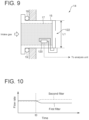
- FIG. 9 is a cross-sectional configuration diagram of a filter according to a third embodiment.
- FIG. 10 is an example of temporal change in flow rate detected by the differential pressure sensor of FIG. 9 .
- FIG. 11 is a flowchart showing steps of a filter unit management method according to the third embodiment.
- FIG. 12 is a cross-sectional configuration diagram of a filter according to a fourth embodiment.
- FIG. 13 is a flowchart showing steps of a filter unit management method according to the fourth embodiment.
- FIG. 14 is a schematic cross-sectional configuration diagram of a filter unit disposed in an intake passage of a gas turbine.
- FIG. 15 is a plan view of one of filter layers included in the filter unit of FIG. 14 viewed from the upstream side of the intake passage.
- an expression of relative or absolute arrangement such as “in a direction”, “along a direction”, “parallel”, “orthogonal”, “centered”, “concentric” and “coaxial” shall not be construed as indicating only the arrangement in a strict literal sense, but also includes a state where the arrangement is relatively displaced by a tolerance, or by an angle or a distance whereby it is possible to achieve the same function.
- an expression of a shape such as a rectangular shape or a cylindrical shape shall not be construed as only the geometrically strict shape, but also includes a shape with unevenness or chamfered corners within the range in which the same effect can be achieved.
- FIG. 1 is a schematic configuration diagram of a filter unit quality management system 100 according to a first embodiment.
- FIG. 2 is a plan view of one of filter layers 12 included in the filter unit 10 of FIG. 1 viewed from the upstream side of the intake passage 1 .
- FIG. 3 is a cross-sectional configuration diagram of a filter 14 included in a filter layer 12 of the filter unit 10 of FIG. 1 .
- the intake passage 1 is a duct connected to the intake side of the gas turbine and introduces gas taken from the outside into the gas turbine.
- the intake passage 1 is provided with a filter unit 10 as a filter device for removing foreign substances such as dust contained in the gas.
- the filter unit 10 includes a plurality of filter layers 12 arranged along the flow direction of intake gas, including a primary filter layer 12 a , a secondary filter layer 12 b , and a tertiary filter layer 12 c in order from the upstream side.
- the intake passage 1 has an inner wall 1 a defining a flow passage cross-section of substantially square shape.
- Each filter layer 12 included in the filter unit 10 has an outer shape corresponding to the flow passage cross-section of the intake passage 1 , and the gas flowing through the intake passage 1 passes through each filter layer 12 and is supplied to the gas turbine on the downstream side.
- Each filter layer 12 includes a plurality of filters 14 arranged along the cross-sectional direction of the intake passage 1 .
- each of the filters 14 includes a filter element 17 accommodated in a housing 15 , and is held in a matrix form by a frame 16 formed in a grid shape between inner walls 1 a that face each other in a substantially vertical cross-section of the intake passage 1 .
- a packing 19 is disposed to prevent the leakage of gas through the gap.
- the filter 14 in each filter layer 12 has a substantially square shape with one side L 1 of, for example, about 600 mm.
- the depth of the primary filter layer 12 a is 100 mm or less, and the depths of the secondary filter layer 12 b and the tertiary filter layer 12 c are 300 mm approximately.
- the number of filters 14 of each filter layer 12 depends on the cross-sectional area of the intake passage 1 , for example, may be several hundreds.
- the filter 14 constituting the primary filter layer 12 a located most upstream in the filter unit 10 has a filter element 17 for collecting foreign substances having a relatively coarse particle size (e.g., 10 ⁇ m or more).
- the filter 14 constituting the secondary filter layer 12 b located downstream of the primary filter 12 a has a filter element 17 which is a medium efficiency filter for collecting foreign substances having a particle size smaller than the primary filter 12 a (e.g., about 1 ⁇ m).
- the filter 14 constituting the tertiary filter layer 12 c located downstream of the secondary filter 12 b has a filter element 17 which is a HEPA filter for collecting foreign substances having a particle size smaller than the secondary filter 12 b (e.g., submicron order).
- the gas taken into the filter unit 10 passes through the filter layers 12 to remove foreign substances, becomes clean, and is discharged downstream. Since a higher filter performance is required on the downstream side, generally, replacements of the filters 14 constituting the filter layer 12 on the downstream side tend to be expensive.
- the filter unit quality management system 100 includes a differential pressure sensor 102 which is an evaluation parameter detection unit provided corresponding to the filter 14 of the filter layer 12 , and an analysis unit 104 for performing analysis based on detection values of the differential pressure sensor 102 .
- the differential pressure sensor 102 is disposed inside the housing 15 of each filter 14 as shown in FIG. 3 , or on an outer surface of the housing 15 .
- the differential pressure sensor 102 detects, as an evaluation parameter relating to the degree of clogging of the corresponding filter 14 , the differential pressure of the filter 14 (as shown in FIG.
- the differential pressure sensor 102 is configured to be able to detect differential pressure from a pressure acquired at a pressure outlet at the upstream end of the filter via a tube 102 a and a pressure acquired at a pressure outlet at the downstream end of the filter via a tube 102 b ).
- the differential pressure sensor 102 is connected to the analysis unit 104 by wireless communication.
- the differential pressure sensor 102 is provided for a large number of filters 14 constituting each filter layer 12 , the space is not occupied by communication cables or the like.
- the analysis unit 104 is composed of, for example, an electronic calculation device such as a computer, and acquires detection values of the differential pressure sensor 102 to evaluate the quality of the filter layer 12 .
- the internal configuration of the analysis unit 104 includes a quality evaluation unit 106 for evaluating the quality of the filter layer 12 based on detection values of the differential pressure sensor 102 , as shown as a functional block in FIG. 1 .
- the analysis unit 104 is configured by reading a program for executing a quality evaluation method described below recorded on a predetermined recording medium into a computer, and installing the program, for instance.
- the analysis unit 104 may be formed integrally with a control unit (not shown) of the gas turbine.
- FIG. 4 is a flowchart showing steps of a quality evaluation method performed by the analysis unit 104 of FIG. 1 .
- the analysis unit 104 continuously acquires detection values of the differential pressure sensor 102 disposed in the filter 14 of each filter layer 12 (step S 10 ).
- the analysis unit 104 acquires temporal change in differential pressure of each filter 14 of each filter layer 12 .
- the quality evaluation unit 106 determines whether there is a transient change in the temporal change in differential pressure detected by the filter 14 , based on detection values of the differential pressure sensor acquired in step S 10 (step S 11 ). Whether there is a transient change is determined, for instance, by continuously monitoring detection values of the differential pressure sensor 102 and determining whether the change amount of differential pressure exceeds a reference value within a predetermined period.
- step S 11 determines a distribution of the differential pressure in the plurality of filters 14 , based on the detection values of the differential pressure sensors 102 (step S 12 ).
- FIG. 5 is an example of temporal change of the differential pressure sensor 102 acquired in step S 10 of FIG. 4 .
- a specific first filter 14 a is clogged as shown in FIG. 2 .
- the temporal change in differential pressure in the clogged first filter 14 a is indicated by the solid line
- the temporal change in differential pressure in a second filter 14 b adjacent to the first filter 14 a is indicated by the dashed line.
- the flow resistance of the first filter 14 a increases, so that the differential pressure temporarily increases.
- the temporarily increased differential pressure decreases after reaching maximum at time t 1 .
- the second filter 14 b adjacent to the first filter 14 a the gas that cannot pass through the first filter 14 a is introduced, so that the differential pressure increases.
- Such an increase in differential pressure of the second filter 14 b occurs at time t 2 which is later than time t 1 .
- pattern A the temporal change in differential pressure corresponding to the clogged first filter 14 a
- pattern B the temporal change in differential pressure corresponding to the second filter 14 b
- step S 12 the distribution is created by evaluating the temporal change in differential pressure in each filter 14 and mapping the first filter 14 a or the second filter 14 b where the transient change having the pattern A or B has occurred.
- FIG. 2 shows an example of the distribution thus created, in which the second filters 14 are disposed so as to surround the clogged first filters 14 a.
- the quality evaluation unit 106 identifies the clogged first filter 14 a based on the distribution created in step S 12 (step S 13 ), and identifies the second filter 14 b based on the distribution created in step S 12 (step S 14 ). Then, the filter life of each filter layer 12 is evaluated by each filter 14 based on the identification results of steps S 13 and S 14 (step S 15 ). Thus, the quality evaluation unit 106 determines which filter 14 is clogged in each filter layer 12 having a large number of filters 14 .
- the first filter 14 a and the second filter 14 b can be identified from the distribution, when the second filter 14 b cannot be identified, a region where clogging has occurred may be identified only by the first filter 14 a . Conversely, when the first filter 14 a cannot be identified, the distribution of the second filters 14 b may be identified to indirectly identify the first filter 14 a adjacent to the second filters 14 b.
- all filters 14 have the differential pressure sensor 102
- when only part of the filters 14 has the differential pressure sensor 102 depending on the position of the filter 14 in which the differential pressure sensor 102 is disposed, it is possible that both the first filter 14 a and the second filter 14 b cannot be directly identified.
- a region where clogging has occurred may be identified only by the first filter 14 a , or the distribution of the second filters 14 b may be identified to indirectly identify the first filter 14 a adjacent to the second filters 14 b.
- the differential pressure sensor 102 for quality management of the filter unit 10 may be provided for all filter layers 12 (primary filter layer 12 a , secondary filter layer 12 b , and tertiary filter layer 12 c ) constituting the filter unit 10 , or may be provided for part of the filter layers 12 . In the latter case, preferably, the differential pressure sensor 102 may be disposed in at least the tertiary filter layer 12 c on the most downstream side. In this case, since the downstream filter layer 12 , which needs much cost for replacement, is selectively managed, it is possible to effectively perform quality management compared with the case where all filter layers 12 are managed.
- the tertiary filter layer 12 c on the most downstream side is of high importance in the operation of the turbine to which the intake gas is supplied, and if this filter layer is damaged, it is likely to affect the operation of the turbine. It is thus preferred that the downstream filter layer 12 is preferentially managed.
- the differential pressure sensor 102 may be provided for all filters 14 constituting the filter layer 12 . In this case, although the cost is high, the quality of all the filters 14 constituting the filter layer 12 can be controlled.
- the differential pressure sensor 102 may be limitedly arranged in filters 14 in a partial region among the filters 14 constituting the filter layer 12 .
- the region where the differential pressure sensor 102 is arranged may be estimated as a region where clogging is likely to occur, from past data and experience.
- the filter unit 10 is sometimes provided in an intake filter chamber of a multi-sided, multi-storey structure.
- soot and dust emitted from surrounding factories and trucks that frequently travel main roads will wind up on the area of turbine, so that the amount of dust and soot tends to increase at the side of the factories and the main roads.
- the amount tends to increase in the lower floors due to the influence of gravity fall.
- FIG. 6 is a cross-sectional configuration diagram of the filter 14 according to a second embodiment.
- the configuration of the filter unit 10 according to the second embodiment is the same as that of the above-described embodiment unless otherwise specified, and corresponding components are designated by common reference numerals.
- the filter 14 according to the second embodiment is provided with, instead of the differential pressure sensor 102 according to the first embodiment, a strain sensor 110 for detecting the degree of strain of the housing 15 of the filter 14 held by the frame 16 .
- the strain sensor 110 is disposed between the frame 16 and the housing 15 so as to be adjacent to the packing 19 , and detects the degree of strain between the frame 16 and the housing 15 .
- the strain sensor 110 is connected to the analysis unit 104 by wireless communication. Thus, even when the strain sensor 110 is provided for a large number of filters 14 constituting each filter layer 12 , the space is not occupied by communication cables or the like.
- FIG. 7 is an example of temporal change in degree of strain detected by the strain sensor 110 of FIG. 6 .
- a specific first filter 14 a is clogged.
- the temporal change in degree of strain in the clogged first filter 14 a is indicated by the solid line
- the temporal change in degree of strain in a second filter 14 b adjacent to the first filter 14 a is indicated by the dashed line.
- the temporal change in degree of strain detected by the strain sensor 110 shows the same tendency as the temporal change in differential pressure detected by the differential pressure sensor 102 of the first embodiment.
- FIG. 8 is a flowchart showing steps of a filter unit management method according to the second embodiment. As shown in steps of FIG. 8 , by treating the transient change in degree of strain detected by the strain sensor 110 in the same manner as the transient change in differential pressure detected by the differential pressure sensor 102 , it is possible to manage quality of the filters 14 of each filter layer 12 .
- the detection target of the strain sensor 110 is strain caused by an increase in flow resistance of the filter 14 that collects foreign substances
- the target may be strain caused by an increase in weight of the filter 14 that collects foreign substances. This case can also be treated in the same manner as described above.
- FIG. 9 is a cross-sectional configuration diagram of the filter 14 according to a third embodiment.
- the configuration of the filter unit 10 according to the third embodiment is the same as that of the above-described embodiment unless otherwise specified, and corresponding components are designated by common reference numerals.
- the filter 14 according to the third embodiment is provided with, instead of the differential pressure sensor 102 according to the first embodiment, a differential pressure sensor 120 for detecting the intake gas flow rate of the filter 14 .
- the differential pressure sensor 120 has an orifice 122 on the downstream side of the housing 15 of the filter 14 , and is configured to be able to detect the flow rate of the gas passing through the filter 14 , based on the differential pressure across the orifice 122 .
- the differential pressure sensor 120 is connected to the analysis unit 104 by wireless communication. Thus, even when the differential pressure sensor 120 is provided for a large number of filters 14 constituting each filter layer 12 , the space is not occupied by communication cables or the like.
- FIG. 10 is an example of temporal change in flow rate detected by the differential pressure sensor 120 of FIG. 9 .
- a specific first filter 14 a is clogged.
- the temporal change in flow rate in the clogged first filter 14 a is indicated by the solid line
- the temporal change in flow rate in a second filter 14 b adjacent to the first filter 14 a is indicated by the dashed line.
- the intake gas flow rate of the first filter 14 a decreases.
- the decrease in intake gas flow rate of the first filter 14 a continues after time t 0 unless the clogging of the first filter 14 a is eliminated.
- the second filter 14 b adjacent to the first filter 14 a the gas that cannot pass through the first filter 14 a is introduced, so that the intake gas flow rate increases.
- the increase in intake gas flow rate of the second filter 14 b also continues after time t 0 unless the clogging of the first filter 14 a is eliminated.
- the temporal change in intake gas flow rate corresponding to the clogged first filter 14 a is referred to as pattern C
- the temporal change in intake gas flow rate corresponding to the second filter 14 b is referred to as pattern D.
- the clogging of each filter 14 can be verified by evaluating whether the intake gas flow rate in each filter 14 is pattern C or D.
- the clogging can be evaluated by an absolute value.
- the clogging is evaluated based on a transient change
- the clogging can be evaluated based on an absolute value, not the transient change.
- FIG. 11 is a flowchart showing steps of a filter unit management method according to the third embodiment.
- the analysis unit 104 acquires detection values of the differential pressure sensor 120 disposed in the filter 14 of each filter layer 12 (step S 30 ). Thus, the analysis unit 104 acquires the intake gas flow rate of each filter 14 constituting each filter layer 12 .
- the quality evaluation unit 106 determines a distribution of the intake gas flow rate in the plurality of filters 14 , based on the detection values of the differential pressure sensors 120 acquired in step S 30 (step S 31 ). Such a distribution of the intake gas flow rate is created by mapping the detection values of each differential pressure sensor 120 into pattern C or D.
- the quality evaluation unit 106 identifies the clogged first filter 14 a based on the distribution created in step S 31 (step S 32 ), and identifies the second filter 14 b based on the distribution created in step S 31 (step S 33 ). Then, the filter life of each filter layer 12 is evaluated by each filter 14 based on the identification results of steps S 32 and S 33 (step S 34 ). Thus, the quality evaluation unit 106 determines which filter 14 is clogged in each filter layer 12 having a large number of filters 14 .
- FIG. 12 is a cross-sectional configuration diagram of the filter 14 according to a fourth embodiment.
- the configuration of the filter unit 10 according to the fourth embodiment is the same as that of the above-described embodiment unless otherwise specified, and corresponding components are designated by common reference numerals.
- the filter 14 includes both the differential pressure sensor 102 same as the first embodiment and the differential pressure sensor 120 same as the third embodiment.
- the analysis unit 104 acquires the differential pressure inside the housing 15 of each filter 14 using the differential pressure sensor 102 , and acquires the flow rate of intake gas passing through each filter 14 using the differential pressure sensor 120 to calculate the flow resistance of each filter 14 based on the differential pressure and the flow rate.
- the flow resistance thus calculated is an evaluation parameter directly indicating the performance of each filter 14 and enables evaluation of the degree of clogging at high precision.
- FIG. 13 is a flowchart showing steps of a filter unit management method according to the fourth embodiment.
- the analysis unit 104 acquires detection values of the differential pressure sensor 102 and the differential pressure sensor 120 disposed in the filter 14 of each filter layer 12 (step S 40 ). Thus, the analysis unit 104 acquires the differential pressure and the intake gas flow rate of each filter 14 constituting each filter layer 12 .
- the quality evaluation unit 106 calculates the flow resistance of each filter 14 based on the detection values of the differential pressure sensor 102 and the differential pressure sensor 120 acquired in step S 40 (step S 41 ), and determines a distribution of the flow resistance in the plurality of filters 14 (step S 42 ).
- the quality evaluation unit 106 identifies the clogged first filter 14 a based on the distribution created in step S 42 (step S 43 ).
- the identification of the first filter 14 a is performed based on, for example, whether the flow resistance exceeds a reference value.
- the above-described embodiments provide the filter unit quality management system and the unit quality management method that enable precise quality control by quantitatively evaluating the performance of each filter 14 in the filter unit 10 including the plurality of filters 14 .
- At least one embodiment of the present invention can be applied to a filter unit quality management system and a filter unit quality management method for quality management of a filter unit for removing foreign substances contained in intake gas flowing through an intake passage.
Landscapes
- Chemical & Material Sciences (AREA)
- Engineering & Computer Science (AREA)
- Combustion & Propulsion (AREA)
- Chemical Kinetics & Catalysis (AREA)
- General Engineering & Computer Science (AREA)
- Mechanical Engineering (AREA)
- Physics & Mathematics (AREA)
- Health & Medical Sciences (AREA)
- General Health & Medical Sciences (AREA)
- General Physics & Mathematics (AREA)
- Immunology (AREA)
- Pathology (AREA)
- Biochemistry (AREA)
- Analytical Chemistry (AREA)
- Life Sciences & Earth Sciences (AREA)
- Dispersion Chemistry (AREA)
- Fluid Mechanics (AREA)
- Filtering Of Dispersed Particles In Gases (AREA)
Abstract
Description
- Patent Document 1: JP2004-346933A
- 1 Intake passage
- 1 a Inner wall
- 10 Filter unit
- 12 Filter layer
- 14 Filter
- 15 Housing
- 16 Frame
- 17 Filter element
- 19 Packing
- 100 Filter unit quality management system
- 102 Differential pressure sensor
- 104 Analysis unit
- 106 Quality evaluation unit
- 110 Strain sensor
- 120 Differential pressure sensor
- 122 Orifice
Claims (16)
Applications Claiming Priority (3)
| Application Number | Priority Date | Filing Date | Title |
|---|---|---|---|
| JP2018015372A JP7105068B2 (en) | 2018-01-31 | 2018-01-31 | Filter unit quality control system and filter unit quality control method |
| JP2018-015372 | 2018-01-31 | ||
| PCT/JP2019/003331 WO2019151383A1 (en) | 2018-01-31 | 2019-01-31 | Filter unit quality management system and filter unit quality management method |
Publications (2)
| Publication Number | Publication Date |
|---|---|
| US20210069624A1 US20210069624A1 (en) | 2021-03-11 |
| US11772032B2 true US11772032B2 (en) | 2023-10-03 |
Family
ID=67479083
Family Applications (1)
| Application Number | Title | Priority Date | Filing Date |
|---|---|---|---|
| US16/962,407 Active 2040-11-06 US11772032B2 (en) | 2018-01-31 | 2019-01-31 | Filter unit quality management system and filter unit quality management method |
Country Status (6)
| Country | Link |
|---|---|
| US (1) | US11772032B2 (en) |
| JP (1) | JP7105068B2 (en) |
| KR (1) | KR102479613B1 (en) |
| CN (1) | CN111601651B (en) |
| DE (1) | DE112019000324B4 (en) |
| WO (1) | WO2019151383A1 (en) |
Cited By (1)
| Publication number | Priority date | Publication date | Assignee | Title |
|---|---|---|---|---|
| US20240393225A1 (en) * | 2021-10-19 | 2024-11-28 | Kobelco Construction Machinery Co., Ltd. | Clogging calculation system, clogging calculation method, and clogging calculation program |
Families Citing this family (4)
| Publication number | Priority date | Publication date | Assignee | Title |
|---|---|---|---|---|
| JP7330872B2 (en) * | 2019-11-29 | 2023-08-22 | 株式会社日立製作所 | FILTER INSPECTION SYSTEM AND FILTER INSPECTION METHOD IN PARTICLE ANALYZER |
| EP3865199B1 (en) * | 2020-02-12 | 2023-09-13 | Carl Freudenberg KG | Filter module with sensor for determining the loading condition and method for determining the loading condition |
| CN112302802A (en) * | 2020-11-13 | 2021-02-02 | 无锡华南钢结构环保有限公司 | Particle air filtering mechanism capable of being replaced quickly for gas turbine |
| CN117949310A (en) * | 2024-01-17 | 2024-04-30 | 兰州理工大学 | A filter skeleton deformation measurement device |
Citations (26)
| Publication number | Priority date | Publication date | Assignee | Title |
|---|---|---|---|---|
| US3766715A (en) * | 1971-05-26 | 1973-10-23 | Erdco Eng Corp | Method and apparatus for combustible gas detection in dirt laden atmosphere |
| US4786293A (en) * | 1987-10-08 | 1988-11-22 | Farr Company | Smart controller for reverse pulse air filter |
| US4824450A (en) * | 1987-11-19 | 1989-04-25 | Howard Arthur G | Air filter apparatus |
| US5572327A (en) * | 1995-02-01 | 1996-11-05 | W. L. Gore & Associates, Inc. | Remote leak detection sensing method and device |
| JPH10151942A (en) | 1996-11-25 | 1998-06-09 | Calsonic Corp | Filter unit of air conditioner |
| JP2004169667A (en) | 2002-11-22 | 2004-06-17 | Mitsubishi Heavy Ind Ltd | Monitoring device of multi-stage filter |
| KR20040060065A (en) | 2002-12-30 | 2004-07-06 | 위니아만도 주식회사 | Alarm system for air filter swapping time of aircondition |
| US20040217872A1 (en) | 2003-05-02 | 2004-11-04 | Bhardwaj Arun K. | Apparatus for and method of monitoring the condition of a filter element |
| US6875256B2 (en) * | 2000-09-05 | 2005-04-05 | Donaldson Company, Inc. | Methods for filtering air for a gas turbine system |
| JP2006009591A (en) | 2004-06-22 | 2006-01-12 | Chugoku Electric Power Co Inc:The | Filter clogging detector and filter management method |
| KR100682797B1 (en) | 2006-03-06 | 2007-02-15 | 주식회사 포스코 | Filter Bag Load Detection Device of Dust Collector |
| US20070039464A1 (en) * | 2005-08-17 | 2007-02-22 | Andrew Corporation | Dry gas production systems for pressurizing a space and methods of operating such systems to produce a dry gas stream |
| JP2008019801A (en) | 2006-07-13 | 2008-01-31 | Mitsubishi Heavy Ind Ltd | Gas turbine intake device and method for operating the same |
| JP2008050965A (en) | 2006-08-23 | 2008-03-06 | Hitachi Ltd | Remaining life calculation method, apparatus for executing this method, remaining life calculation program |
| US20090107337A1 (en) * | 2007-10-31 | 2009-04-30 | Huong Van Vu | Automatic pulse cartridge cleaning system and method |
| US8075674B2 (en) * | 2006-11-30 | 2011-12-13 | Donaldson Company, Inc. | Filter apparatus with pulse cleaning and methods for pulse cleaning filters |
| US20110314776A1 (en) * | 2008-07-14 | 2011-12-29 | Tenoroc, Llc | Aerodynamic separation nozzle |
| US8114196B2 (en) * | 2009-08-31 | 2012-02-14 | General Electric Company | Gas turbine inlet filter house cleaning apparatus and method |
| US8721753B2 (en) * | 2010-05-11 | 2014-05-13 | Bha Altair, Llc | Method and apparatus for an air filter cartridge replacement assembly |
| US8747533B1 (en) * | 2013-01-28 | 2014-06-10 | Bha Altair, Llc | Systems and methods to determine fouling in a gas turbine filter |
| US20140208942A1 (en) | 2013-01-28 | 2014-07-31 | General Electric Company | Method, Apparatus, And System For Air Filter Cleaning |
| JP2015190452A (en) | 2014-03-28 | 2015-11-02 | 三菱日立パワーシステムズ株式会社 | Filter management device and intake duct |
| KR20150139664A (en) | 2014-06-03 | 2015-12-14 | 코웨이 주식회사 | Air purifier and method for determining filter exchange period thereof |
| US20170002821A1 (en) | 2014-03-18 | 2017-01-05 | Siemens Energy, Inc. | System for measuring air mass flow into a gas turbine |
| US20170320004A1 (en) | 2014-12-05 | 2017-11-09 | Nuovo Pignone Srl | Method and system for predicting residual useful life of an air filter |
| EP3409923A1 (en) | 2017-05-30 | 2018-12-05 | General Electric Company | System and method for condition-based monitoring of filters |
Family Cites Families (9)
| Publication number | Priority date | Publication date | Assignee | Title |
|---|---|---|---|---|
| GB9605115D0 (en) * | 1996-03-07 | 1996-05-08 | British American Tobacco Co | Air treatment |
| JP2002366688A (en) * | 2001-06-08 | 2002-12-20 | Mitsubishi Heavy Ind Ltd | Managing method for filter and filter to be managed by the same |
| NL1020621C2 (en) * | 2002-05-17 | 2003-11-18 | Norit Membraan Tech Bv | Method for cleaning a liquid filtration system. |
| US8182587B2 (en) * | 2008-08-28 | 2012-05-22 | General Electric Company | Filtration system for gas turbines |
| JP2013148045A (en) * | 2012-01-20 | 2013-08-01 | Mitsubishi Heavy Ind Ltd | Exhaust emission control system of engine |
| JP6460371B2 (en) * | 2014-05-23 | 2019-01-30 | 三菱日立パワーシステムズ株式会社 | Intake filter device, filter replacement method for intake filter device, and gas turbine |
| CN105498374A (en) * | 2015-11-30 | 2016-04-20 | 杨凌金海生物技术有限公司 | High-efficiency filtering case |
| CN206809951U (en) * | 2017-04-12 | 2017-12-29 | 苏州龙桥环保科技有限公司 | A kind of relief valve unloading gas filter |
| CN206847922U (en) * | 2017-05-26 | 2018-01-05 | 霍拓普燕森(青岛)环保设备有限公司 | A kind of pressure difference monitoring device for being used to judge life-span of filtering material |
-
2018
- 2018-01-31 JP JP2018015372A patent/JP7105068B2/en active Active
-
2019
- 2019-01-31 WO PCT/JP2019/003331 patent/WO2019151383A1/en not_active Ceased
- 2019-01-31 CN CN201980008370.0A patent/CN111601651B/en active Active
- 2019-01-31 US US16/962,407 patent/US11772032B2/en active Active
- 2019-01-31 DE DE112019000324.0T patent/DE112019000324B4/en active Active
- 2019-01-31 KR KR1020207020872A patent/KR102479613B1/en active Active
Patent Citations (27)
| Publication number | Priority date | Publication date | Assignee | Title |
|---|---|---|---|---|
| US3766715A (en) * | 1971-05-26 | 1973-10-23 | Erdco Eng Corp | Method and apparatus for combustible gas detection in dirt laden atmosphere |
| US4786293A (en) * | 1987-10-08 | 1988-11-22 | Farr Company | Smart controller for reverse pulse air filter |
| US4824450A (en) * | 1987-11-19 | 1989-04-25 | Howard Arthur G | Air filter apparatus |
| US5572327A (en) * | 1995-02-01 | 1996-11-05 | W. L. Gore & Associates, Inc. | Remote leak detection sensing method and device |
| JPH10151942A (en) | 1996-11-25 | 1998-06-09 | Calsonic Corp | Filter unit of air conditioner |
| US6875256B2 (en) * | 2000-09-05 | 2005-04-05 | Donaldson Company, Inc. | Methods for filtering air for a gas turbine system |
| JP2004169667A (en) | 2002-11-22 | 2004-06-17 | Mitsubishi Heavy Ind Ltd | Monitoring device of multi-stage filter |
| KR20040060065A (en) | 2002-12-30 | 2004-07-06 | 위니아만도 주식회사 | Alarm system for air filter swapping time of aircondition |
| US20040217872A1 (en) | 2003-05-02 | 2004-11-04 | Bhardwaj Arun K. | Apparatus for and method of monitoring the condition of a filter element |
| JP2004346933A (en) | 2003-05-02 | 2004-12-09 | Arvin Technologies Inc | Device and method for monitoring state of filter element |
| JP2006009591A (en) | 2004-06-22 | 2006-01-12 | Chugoku Electric Power Co Inc:The | Filter clogging detector and filter management method |
| US20070039464A1 (en) * | 2005-08-17 | 2007-02-22 | Andrew Corporation | Dry gas production systems for pressurizing a space and methods of operating such systems to produce a dry gas stream |
| KR100682797B1 (en) | 2006-03-06 | 2007-02-15 | 주식회사 포스코 | Filter Bag Load Detection Device of Dust Collector |
| JP2008019801A (en) | 2006-07-13 | 2008-01-31 | Mitsubishi Heavy Ind Ltd | Gas turbine intake device and method for operating the same |
| JP2008050965A (en) | 2006-08-23 | 2008-03-06 | Hitachi Ltd | Remaining life calculation method, apparatus for executing this method, remaining life calculation program |
| US8075674B2 (en) * | 2006-11-30 | 2011-12-13 | Donaldson Company, Inc. | Filter apparatus with pulse cleaning and methods for pulse cleaning filters |
| US20090107337A1 (en) * | 2007-10-31 | 2009-04-30 | Huong Van Vu | Automatic pulse cartridge cleaning system and method |
| US20110314776A1 (en) * | 2008-07-14 | 2011-12-29 | Tenoroc, Llc | Aerodynamic separation nozzle |
| US8114196B2 (en) * | 2009-08-31 | 2012-02-14 | General Electric Company | Gas turbine inlet filter house cleaning apparatus and method |
| US8721753B2 (en) * | 2010-05-11 | 2014-05-13 | Bha Altair, Llc | Method and apparatus for an air filter cartridge replacement assembly |
| US8747533B1 (en) * | 2013-01-28 | 2014-06-10 | Bha Altair, Llc | Systems and methods to determine fouling in a gas turbine filter |
| US20140208942A1 (en) | 2013-01-28 | 2014-07-31 | General Electric Company | Method, Apparatus, And System For Air Filter Cleaning |
| US20170002821A1 (en) | 2014-03-18 | 2017-01-05 | Siemens Energy, Inc. | System for measuring air mass flow into a gas turbine |
| JP2015190452A (en) | 2014-03-28 | 2015-11-02 | 三菱日立パワーシステムズ株式会社 | Filter management device and intake duct |
| KR20150139664A (en) | 2014-06-03 | 2015-12-14 | 코웨이 주식회사 | Air purifier and method for determining filter exchange period thereof |
| US20170320004A1 (en) | 2014-12-05 | 2017-11-09 | Nuovo Pignone Srl | Method and system for predicting residual useful life of an air filter |
| EP3409923A1 (en) | 2017-05-30 | 2018-12-05 | General Electric Company | System and method for condition-based monitoring of filters |
Non-Patent Citations (3)
| Title |
|---|
| International Preliminary Report on Patentability dated Aug. 13, 2020 in International (PCT) Patent Application No. PCT/JP2019/003331, with English Translation. |
| International Search Report dated Apr. 2, 2019 in International (PCT) Patent Application No. PCT/JP2019/003331, with English Translation. |
| Office Action dated Nov. 15, 2021 in counterpart Korean Patent Application No. 10-2020-7020872, with English-language translation. |
Cited By (1)
| Publication number | Priority date | Publication date | Assignee | Title |
|---|---|---|---|---|
| US20240393225A1 (en) * | 2021-10-19 | 2024-11-28 | Kobelco Construction Machinery Co., Ltd. | Clogging calculation system, clogging calculation method, and clogging calculation program |
Also Published As
| Publication number | Publication date |
|---|---|
| CN111601651B (en) | 2022-02-18 |
| DE112019000324T5 (en) | 2020-10-08 |
| CN111601651A (en) | 2020-08-28 |
| KR102479613B1 (en) | 2022-12-20 |
| WO2019151383A1 (en) | 2019-08-08 |
| DE112019000324B4 (en) | 2024-01-04 |
| JP2019130487A (en) | 2019-08-08 |
| US20210069624A1 (en) | 2021-03-11 |
| KR20200096841A (en) | 2020-08-13 |
| JP7105068B2 (en) | 2022-07-22 |
Similar Documents
| Publication | Publication Date | Title |
|---|---|---|
| US11772032B2 (en) | Filter unit quality management system and filter unit quality management method | |
| US9931591B2 (en) | Method and system for detecting dust accumulation in a HVAC filtering system | |
| US9120044B2 (en) | Fume extraction | |
| US20180093215A1 (en) | Dust collector control system | |
| US10137397B2 (en) | Filter systems | |
| US11865482B2 (en) | Filter module comprising sensor and method for determining the state of a filter element | |
| TWI745912B (en) | Blast furnace abnormality determination device, blast furnace abnormality determination method and blast furnace operation method | |
| KR102139147B1 (en) | Filtration and dust collector monitoring system | |
| CN111422028A (en) | Monitoring method and monitoring device for air conditioner filter element and vehicle-mounted air conditioning system | |
| KR102373745B1 (en) | Method for determining the degree of wear of a valve, and apparatus for carrying out said method | |
| JP2019130487A5 (en) | ||
| CN115680794A (en) | Sensing system and method for constructing an intelligent model of particle entry detection in a turbine system | |
| CN103899452A (en) | Method for monitoring air filter of diesel engine applicable to plateau and locomotive applicable to plateau | |
| EP3071815B1 (en) | Systems and methods for managing turbine intake filters | |
| CN211144994U (en) | A hydraulic oil tank filter element detection device and hydraulic system | |
| US12618375B2 (en) | Systems and methods for estimating integrity and efficiency of an inlet filtration system for turbine systems and for recommending mitigation actions | |
| EP4124723A1 (en) | Systems and methods for estimating integrity and efficiency of an inlet filtration system for turbine systems and for recommending mitigation actions | |
| CN101865578B (en) | Method for monitoring air conditioning unit by using oil pressure | |
| CN121533647A (en) | A method and system for monitoring the filter pore size efficiency of a vacuum cleaner | |
| Dong et al. | Application status of intelligent monitoring technology for bag leakage in baghouse dust collectors | |
| CN119139814A (en) | Natural gas filtering system and method | |
| CN121205764A (en) | DPF Fault Diagnosis Methods, Devices, Equipment and Media | |
| CN121274364A (en) | Energy-saving air conditioner air filter blockage detection method and system | |
| CN118815792A (en) | Grain silo full hydraulic cleaning machine electronic control system | |
| JP2013156059A (en) | Particle inspection method and particle inspection system |
Legal Events
| Date | Code | Title | Description |
|---|---|---|---|
| AS | Assignment |
Owner name: MITSUBISHI HITACHI POWER SYSTEMS, LTD., JAPAN Free format text: ASSIGNMENT OF ASSIGNORS INTEREST;ASSIGNORS:TAKEI, REI;DOI, YOSHIYUKI;KATAYAMA, HIROYUKI;AND OTHERS;REEL/FRAME:053219/0643 Effective date: 20200608 |
|
| FEPP | Fee payment procedure |
Free format text: ENTITY STATUS SET TO UNDISCOUNTED (ORIGINAL EVENT CODE: BIG.); ENTITY STATUS OF PATENT OWNER: LARGE ENTITY |
|
| STPP | Information on status: patent application and granting procedure in general |
Free format text: APPLICATION DISPATCHED FROM PREEXAM, NOT YET DOCKETED |
|
| AS | Assignment |
Owner name: MITSUBISHI POWER, LTD., JAPAN Free format text: CHANGE OF NAME;ASSIGNOR:MITSUBISHI HITACHI POWER SYSTEMS, LTD.;REEL/FRAME:055051/0532 Effective date: 20200901 |
|
| STPP | Information on status: patent application and granting procedure in general |
Free format text: DOCKETED NEW CASE - READY FOR EXAMINATION |
|
| AS | Assignment |
Owner name: MITSUBISHI HEAVY INDUSTRIES, LTD., JAPAN Free format text: ASSIGNMENT OF ASSIGNORS INTEREST;ASSIGNOR:MITSUBISHI POWER, LTD.;REEL/FRAME:059519/0494 Effective date: 20220217 |
|
| STPP | Information on status: patent application and granting procedure in general |
Free format text: NON FINAL ACTION MAILED |
|
| STPP | Information on status: patent application and granting procedure in general |
Free format text: NOTICE OF ALLOWANCE MAILED -- APPLICATION RECEIVED IN OFFICE OF PUBLICATIONS |
|
| STPP | Information on status: patent application and granting procedure in general |
Free format text: PUBLICATIONS -- ISSUE FEE PAYMENT RECEIVED |
|
| STPP | Information on status: patent application and granting procedure in general |
Free format text: PUBLICATIONS -- ISSUE FEE PAYMENT VERIFIED |
|
| STCF | Information on status: patent grant |
Free format text: PATENTED CASE |