US11768003B2 - Variable refrigerant flow system with zone grouping - Google Patents
Variable refrigerant flow system with zone grouping Download PDFInfo
- Publication number
- US11768003B2 US11768003B2 US17/491,840 US202117491840A US11768003B2 US 11768003 B2 US11768003 B2 US 11768003B2 US 202117491840 A US202117491840 A US 202117491840A US 11768003 B2 US11768003 B2 US 11768003B2
- Authority
- US
- United States
- Prior art keywords
- zone
- zones
- data
- controller
- grouping
- Prior art date
- Legal status (The legal status is an assumption and is not a legal conclusion. Google has not performed a legal analysis and makes no representation as to the accuracy of the status listed.)
- Active
Links
- 239000003507 refrigerant Substances 0.000 title claims description 51
- 238000001816 cooling Methods 0.000 claims abstract description 33
- 238000010438 heat treatment Methods 0.000 claims abstract description 33
- 238000000034 method Methods 0.000 claims description 67
- 230000008569 process Effects 0.000 claims description 48
- 238000004422 calculation algorithm Methods 0.000 claims description 28
- 238000005265 energy consumption Methods 0.000 claims description 7
- 238000004891 communication Methods 0.000 description 18
- 238000012545 processing Methods 0.000 description 9
- 238000010586 diagram Methods 0.000 description 6
- 230000006870 function Effects 0.000 description 6
- 238000012546 transfer Methods 0.000 description 5
- 230000008901 benefit Effects 0.000 description 4
- 238000012549 training Methods 0.000 description 4
- 230000007613 environmental effect Effects 0.000 description 3
- 238000012986 modification Methods 0.000 description 3
- 230000004048 modification Effects 0.000 description 3
- 230000004044 response Effects 0.000 description 3
- 230000001413 cellular effect Effects 0.000 description 2
- 239000007788 liquid Substances 0.000 description 2
- 238000012544 monitoring process Methods 0.000 description 2
- 238000011084 recovery Methods 0.000 description 2
- 238000003491 array Methods 0.000 description 1
- 230000008859 change Effects 0.000 description 1
- 238000007621 cluster analysis Methods 0.000 description 1
- 239000003086 colorant Substances 0.000 description 1
- 238000010276 construction Methods 0.000 description 1
- 238000007405 data analysis Methods 0.000 description 1
- 238000013480 data collection Methods 0.000 description 1
- 238000013461 design Methods 0.000 description 1
- 230000009977 dual effect Effects 0.000 description 1
- 230000000694 effects Effects 0.000 description 1
- 230000005611 electricity Effects 0.000 description 1
- 238000003064 k means clustering Methods 0.000 description 1
- 239000000463 material Substances 0.000 description 1
- 230000003287 optical effect Effects 0.000 description 1
- 238000005457 optimization Methods 0.000 description 1
- 238000005057 refrigeration Methods 0.000 description 1
- 238000006467 substitution reaction Methods 0.000 description 1
- 230000001960 triggered effect Effects 0.000 description 1
Images


Classifications
-
- F—MECHANICAL ENGINEERING; LIGHTING; HEATING; WEAPONS; BLASTING
- F24—HEATING; RANGES; VENTILATING
- F24F—AIR-CONDITIONING; AIR-HUMIDIFICATION; VENTILATION; USE OF AIR CURRENTS FOR SCREENING
- F24F11/00—Control or safety arrangements
- F24F11/62—Control or safety arrangements characterised by the type of control or by internal processing, e.g. using fuzzy logic, adaptive control or estimation of values
- F24F11/63—Electronic processing
-
- F—MECHANICAL ENGINEERING; LIGHTING; HEATING; WEAPONS; BLASTING
- F24—HEATING; RANGES; VENTILATING
- F24F—AIR-CONDITIONING; AIR-HUMIDIFICATION; VENTILATION; USE OF AIR CURRENTS FOR SCREENING
- F24F1/00—Room units for air-conditioning, e.g. separate or self-contained units or units receiving primary air from a central station
- F24F1/0003—Room units for air-conditioning, e.g. separate or self-contained units or units receiving primary air from a central station characterised by a split arrangement, wherein parts of the air-conditioning system, e.g. evaporator and condenser, are in separately located units
-
- F—MECHANICAL ENGINEERING; LIGHTING; HEATING; WEAPONS; BLASTING
- F24—HEATING; RANGES; VENTILATING
- F24F—AIR-CONDITIONING; AIR-HUMIDIFICATION; VENTILATION; USE OF AIR CURRENTS FOR SCREENING
- F24F11/00—Control or safety arrangements
- F24F11/62—Control or safety arrangements characterised by the type of control or by internal processing, e.g. using fuzzy logic, adaptive control or estimation of values
- F24F11/63—Electronic processing
- F24F11/64—Electronic processing using pre-stored data
-
- F—MECHANICAL ENGINEERING; LIGHTING; HEATING; WEAPONS; BLASTING
- F24—HEATING; RANGES; VENTILATING
- F24F—AIR-CONDITIONING; AIR-HUMIDIFICATION; VENTILATION; USE OF AIR CURRENTS FOR SCREENING
- F24F11/00—Control or safety arrangements
- F24F11/62—Control or safety arrangements characterised by the type of control or by internal processing, e.g. using fuzzy logic, adaptive control or estimation of values
- F24F11/63—Electronic processing
- F24F11/65—Electronic processing for selecting an operating mode
- F24F11/67—Switching between heating and cooling modes
-
- F—MECHANICAL ENGINEERING; LIGHTING; HEATING; WEAPONS; BLASTING
- F24—HEATING; RANGES; VENTILATING
- F24F—AIR-CONDITIONING; AIR-HUMIDIFICATION; VENTILATION; USE OF AIR CURRENTS FOR SCREENING
- F24F3/00—Air-conditioning systems in which conditioned primary air is supplied from one or more central stations to distributing units in the rooms or spaces where it may receive secondary treatment; Apparatus specially designed for such systems
- F24F3/06—Air-conditioning systems in which conditioned primary air is supplied from one or more central stations to distributing units in the rooms or spaces where it may receive secondary treatment; Apparatus specially designed for such systems characterised by the arrangements for the supply of heat-exchange fluid for the subsequent treatment of primary air in the room units
- F24F3/065—Air-conditioning systems in which conditioned primary air is supplied from one or more central stations to distributing units in the rooms or spaces where it may receive secondary treatment; Apparatus specially designed for such systems characterised by the arrangements for the supply of heat-exchange fluid for the subsequent treatment of primary air in the room units with a plurality of evaporators or condensers
-
- F—MECHANICAL ENGINEERING; LIGHTING; HEATING; WEAPONS; BLASTING
- F24—HEATING; RANGES; VENTILATING
- F24F—AIR-CONDITIONING; AIR-HUMIDIFICATION; VENTILATION; USE OF AIR CURRENTS FOR SCREENING
- F24F3/00—Air-conditioning systems in which conditioned primary air is supplied from one or more central stations to distributing units in the rooms or spaces where it may receive secondary treatment; Apparatus specially designed for such systems
- F24F3/06—Air-conditioning systems in which conditioned primary air is supplied from one or more central stations to distributing units in the rooms or spaces where it may receive secondary treatment; Apparatus specially designed for such systems characterised by the arrangements for the supply of heat-exchange fluid for the subsequent treatment of primary air in the room units
- F24F3/10—Air-conditioning systems in which conditioned primary air is supplied from one or more central stations to distributing units in the rooms or spaces where it may receive secondary treatment; Apparatus specially designed for such systems characterised by the arrangements for the supply of heat-exchange fluid for the subsequent treatment of primary air in the room units with separate supply lines and common return line for hot and cold heat-exchange fluids i.e. so-called "3-conduit" system
-
- G—PHYSICS
- G05—CONTROLLING; REGULATING
- G05B—CONTROL OR REGULATING SYSTEMS IN GENERAL; FUNCTIONAL ELEMENTS OF SUCH SYSTEMS; MONITORING OR TESTING ARRANGEMENTS FOR SUCH SYSTEMS OR ELEMENTS
- G05B19/00—Programme-control systems
- G05B19/02—Programme-control systems electric
- G05B19/04—Programme control other than numerical control, i.e. in sequence controllers or logic controllers
- G05B19/042—Programme control other than numerical control, i.e. in sequence controllers or logic controllers using digital processors
-
- F—MECHANICAL ENGINEERING; LIGHTING; HEATING; WEAPONS; BLASTING
- F24—HEATING; RANGES; VENTILATING
- F24F—AIR-CONDITIONING; AIR-HUMIDIFICATION; VENTILATION; USE OF AIR CURRENTS FOR SCREENING
- F24F2110/00—Control inputs relating to air properties
- F24F2110/10—Temperature
-
- F—MECHANICAL ENGINEERING; LIGHTING; HEATING; WEAPONS; BLASTING
- F24—HEATING; RANGES; VENTILATING
- F24F—AIR-CONDITIONING; AIR-HUMIDIFICATION; VENTILATION; USE OF AIR CURRENTS FOR SCREENING
- F24F2110/00—Control inputs relating to air properties
- F24F2110/10—Temperature
- F24F2110/12—Temperature of the outside air
-
- F—MECHANICAL ENGINEERING; LIGHTING; HEATING; WEAPONS; BLASTING
- F24—HEATING; RANGES; VENTILATING
- F24F—AIR-CONDITIONING; AIR-HUMIDIFICATION; VENTILATION; USE OF AIR CURRENTS FOR SCREENING
- F24F2120/00—Control inputs relating to users or occupants
- F24F2120/10—Occupancy
-
- F—MECHANICAL ENGINEERING; LIGHTING; HEATING; WEAPONS; BLASTING
- F24—HEATING; RANGES; VENTILATING
- F24F—AIR-CONDITIONING; AIR-HUMIDIFICATION; VENTILATION; USE OF AIR CURRENTS FOR SCREENING
- F24F2140/00—Control inputs relating to system states
-
- F—MECHANICAL ENGINEERING; LIGHTING; HEATING; WEAPONS; BLASTING
- F24—HEATING; RANGES; VENTILATING
- F24F—AIR-CONDITIONING; AIR-HUMIDIFICATION; VENTILATION; USE OF AIR CURRENTS FOR SCREENING
- F24F2140/00—Control inputs relating to system states
- F24F2140/60—Energy consumption
-
- F—MECHANICAL ENGINEERING; LIGHTING; HEATING; WEAPONS; BLASTING
- F24—HEATING; RANGES; VENTILATING
- F24F—AIR-CONDITIONING; AIR-HUMIDIFICATION; VENTILATION; USE OF AIR CURRENTS FOR SCREENING
- F24F2221/00—Details or features not otherwise provided for
- F24F2221/54—Heating and cooling, simultaneously or alternatively
-
- G—PHYSICS
- G05—CONTROLLING; REGULATING
- G05B—CONTROL OR REGULATING SYSTEMS IN GENERAL; FUNCTIONAL ELEMENTS OF SUCH SYSTEMS; MONITORING OR TESTING ARRANGEMENTS FOR SUCH SYSTEMS OR ELEMENTS
- G05B2219/00—Program-control systems
- G05B2219/20—Pc systems
- G05B2219/26—Pc applications
- G05B2219/2614—HVAC, heating, ventillation, climate control
Definitions
- VRF variable refrigerant flow
- a VRF system typically includes one or more outdoor VRF units that consume electrical power to heat and/or cool a refrigerant.
- VRF systems also typically include multiple indoor VRF units located in various spaces of a building, each of which receives the refrigerant from the outdoor VRF unit(s) and uses the refrigerant to transfer heat into or out of a particular space.
- One implementation of the present disclosure is a controller for a building control system.
- the controller includes processors and memory storing instructions that, when executed by the processors, cause the processors to perform operations including identifying zones within a building, analyzing data associated with the zones, and generating zone groupings based on the data associated with the zones.
- Each of the zone groupings define zone groups and specify which of the zones are grouped together to form each of the zone groups.
- the operations also include identifying a particular zone grouping from zone groupings based on the data associated with zones and using the particular zone grouping to generate control signals to operate equipment of the building control system to provide heating or cooling to the zones.
- the data associated with the zones includes historical zone temperature set points of the zones and historical energy consumption values of the zones.
- the operations further involve generating one zone grouping that is the particular zone grouping defining a plurality of zone groups and specifying which of the plurality of zones are grouped together to form each of the plurality of zone groups.
- analyzing the data associated with the zones involves selecting clustering algorithms to identify clusters of the data associated with the zones and generating the particular zone grouping based on the clusters of the data associated with the zones. In some embodiments, analyzing the data associated with the zones involves preclustering the zones into clusters based on location data of the zones to generate a preclustering of zones, comparing the preclustering of zones with the clusters of the data associated with the zones to determine similarities between the preclustering of zones and the clusters, and generating the particular zone grouping based on the similarities between the preclustering of zones and the clusters.
- the controller includes a zone identifier that identifies zones within a building, a zone data collector that collects data associated with the zones within the building, a zone grouping generator module and a control signal generator.
- the zone grouping generator module generates zone groupings defining zone groups and specifying which of the zones identified by the zone identifier are grouped together to form each of the zone groups, analyzes the data collected by the zone data collector, and identifies a particular zone grouping from the zone groupings based on the data associated with the zones.
- the control signal generator uses the particular zone grouping determined by the zone grouping generator module to generate control signals to operate equipment of the building control system to provide heating or cooling to the zones.
- the zone data collector collects data associated with the zones within the building including historical zone temperature set points of the zones and energy consumption values of the zones.
- the zone grouping generator module blocks each type of data included in the data for each of the zones over a predetermined time period to generate data blocks for each of the zones and selects key features associated with the data blocks.
- the zone grouping generator module is further configured to generate one zone grouping that is the particular zone grouping defining a plurality of zone groups and specifying which of the plurality of zones are grouped together to form each of the plurality of zone groups.
- the zone grouping generator module selects clustering algorithms to identify clusters of the data associated with the zones and generates the particular zone grouping based on the clusters of the data associated with the zones.
- the zone grouping generator preclusters the zones into clusters based on location data of zones to generate a preclustering of zones, compares the preclustering of zones with the clusters of the data associated with the zones to determine similarities between the preclustering of zones and the clusters, and generates the particular zone grouping based on the similarities between the preclustering of zones and the clusters.
- Yet another implementation of the present disclosure is a method for operating equipment of a building control system to provide heating or cooling to zones.
- the method involves identifying the zones within a building, analyzing data associated with the zones, generating, based on the data associated with the zones, zone groupings that define zone groups and specify which of the zones are grouped together to form each of the zone groups, identifying a particular zone grouping from the zone groupings based on the data associated with the zones, and using the particular zone grouping to generate control signals to operate equipment of the building control system to provide heating or cooling to the zones.
- analyzing the data associated with the zones involves grouping each type of data included in the data for each of the zones over a predetermined time period to generate data blocks for each of zones and selecting key features associated with the data blocks.
- the method further involves generating one zone grouping that is the particular zone grouping defining a plurality of zone groups and specifying which of the plurality of zones are grouped together to form each of the plurality of zone groups.
- analyzing the data associated with the zones further involves preclustering the zones into clusters based on location data of the zones to generate a preclustering of zones, comparing the preclustering of zones with the clusters of data associated with the zones to determine similarities between the preclustering of zones and the clusters, and generating the particular zone grouping based on the similarities between the preclustering of zones and the clusters.
- a controller for a building control system includes one or more processors and memory storing instructions that, when executed by the one or more processors, cause the one or more processors to perform operations.
- the operations include receiving user inputs and piping data for identifying groupings of zones and generating a model for a particular zone group of the groupings of zones using the user inputs and the piping data.
- the particular zone group comprising a plurality of zones.
- a controller for a building control system includes one or more processors and memory storing instructions that, when executed by the one or more processors, cause the one or more processors to perform operations.
- the operations include receiving piping data associated with equipment in a plurality of zones, generating one or more zone groupings based at least in part on the piping data associated with the plurality of zones, each of the one or more zone groupings defining a plurality of zone groups and specifying which of the plurality of zones are grouped together to form each of the plurality of zone groups, and using the particular zone grouping to generate one or more control signals configured to operate equipment of the building control system to provide heating or cooling to the plurality of zones.
- Some embodiments relate to a controller for a building control system, the controller comprising one or more processors configured to receive user input data associated an initial configuration of a plurality of zones, generate one or more zone groupings based at least in part on the user input data and equipment data associated with the plurality of zones, each of the one or more zone groupings defining a plurality of zone groups and specifying which of the plurality of zones are grouped together to form each of the plurality of zone groups, and use the particular zone grouping to generate one or more control signals configured to operate equipment of the building control system to provide heating or cooling to the plurality of zones.
- FIG. 1 B is a second illustration of a variable refrigerant flow system for a building, according to an exemplary embodiment.
- FIG. 2 is a detailed diagram of a variable refrigerant flow system for a building, according to an exemplary embodiment.
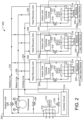
- FIG. 3 is a block diagram of a VRF controller implemented with the variable refrigerant flow system of FIG. 2 , according to an exemplary embodiment.
- FIG. 4 is a block diagram of a zone grouping generator implemented with the VRF controller of FIG. 3 , according to an exemplary embodiment.
- FIG. 5 A is a first example of a zone grouping generated by the zone grouping generator of FIG. 4 , according to an exemplary embodiment.
- FIG. 6 is flowchart of the general VRF control process including zone grouping generation, according to an exemplary embodiment.
- FIG. 7 is a flowchart of the zone grouping generation process implemented in the VRF control process of FIG. 6 , according to an exemplary embodiment.
- FIG. 8 is a flowchart illustrating the data analysis process implemented in the zone grouping generation process of FIG. 7 , according to an exemplary embodiment.
- the VRF system includes a VRF controller configured to operate equipment included in the VRF system, according to some embodiments.
- the VRF controller is configured to operate equipment included in the VRF system using control signals to provide heating and/or cooling loads to various spaces included in a structure, according to some embodiments.
- the various spaces included in the structure are grouped together to form one or more zone groups, according to some embodiments.
- the VRF controller is configured to identify each zone included in the structure, analyze data associated with each zone, generate zone groupings based on the analyzed data, and output one or more zone groupings for use in VRF control, according to some embodiments.
- the VRF controller assists a user with the commissioning of a VRF system by reducing the number of zone grouping iterations performed by the user.
- VRF system 100 is shown to include one or more outdoor VRF units 102 and a plurality of indoor VRF units 104 .
- Outdoor VRF units 102 can be located outside a building and can operate to heat or cool a refrigerant. Outdoor VRF units 102 can consume electricity to convert refrigerant between liquid, gas, and/or super-heated gas phases.
- Indoor VRF units 104 can be distributed throughout various building zones within a building and can receive the heated or cooled refrigerant from outdoor VRF units 102 . Each indoor VRF unit 104 can provide temperature control for the particular building zone in which the indoor VRF unit 104 is located.
- indoor VRF units 104 are typically located inside of buildings, in some cases one or more indoor VRF units are located “outdoors” (i.e., outside of a building) for example to heat/cool a patio, entryway, walkway, etc.
- VRF system 100 provides some indoor VRF units 104 in a cooling mode while other indoor VRF units 104 operate in a heating mode.
- each of outdoor VRF units 102 and indoor VRF units 104 can operate in a heating mode, a cooling mode, or an off mode.
- Each building zone can be controlled independently and can have different temperature setpoints.
- each building has up to three outdoor VRF units 102 located outside the building (e.g., on a rooftop) and up to 128 indoor VRF units 104 distributed throughout the building (e.g., in various building zones). Building zones may include, among other possibilities, apartment units, offices, retail spaces, and common areas. In some cases, various building zones are owned, leased, or otherwise occupied by a variety of tenants, all served by the VRF system 100 .
- VRF system 100 is a two-pipe system in which each outdoor VRF unit 102 connects to a single refrigerant return line and a single refrigerant outlet line. In a two-pipe system, all of outdoor VRF units 102 may operate in the same mode since only one of a heated or chilled refrigerant can be provided via the single refrigerant outlet line. In other embodiments, VRF system 100 is a three-pipe system in which each outdoor VRF unit 102 connects to a refrigerant return line, a hot refrigerant outlet line, and a cold refrigerant outlet line. In a three-pipe system, both heating and cooling can be provided simultaneously via the dual refrigerant outlet lines. An example of a three-pipe VRF system is described in detail with reference to FIG. 2 .
- VRF system 200 is shown to include outdoor VRF unit 202 , several heat recovery units 206 , and several indoor VRF units 204 .
- FIG. 2 shows one outdoor VRF unit 202 , embodiments including multiple outdoor VRF units 202 are also within the scope of the present disclosure.
- Outdoor VRF unit 202 may include a compressor 208 , a fan 210 , or other power-consuming refrigeration components configured convert a refrigerant between liquid, gas, and/or super-heated gas phases.
- Indoor VRF units 204 can be distributed throughout various building zones within a building and can receive the heated or cooled refrigerant from outdoor VRF unit 202 .
- Each indoor VRF unit 204 can provide temperature control for the particular building zone in which the indoor VRF unit 204 is located.
- Heat recovery units 206 can control the flow of a refrigerant between outdoor VRF unit 202 and indoor VRF units 204 (e.g., by opening or closing valves) and can minimize the heating or cooling load to be served by outdoor VRF unit 202 .
- Outdoor VRF unit 202 is shown to include a compressor 208 and a heat exchanger 212 .
- Compressor 208 circulates a refrigerant between heat exchanger 212 and indoor VRF units 204 .
- the compressor 208 operates at a variable frequency as controlled by VRF Controller 214 . At higher frequencies, the compressor 208 provides the indoor VRF units 204 with greater heat transfer capacity. Electrical power consumption of compressor 208 increases proportionally with compressor frequency.
- Heat exchanger 212 can function as a condenser (allowing the refrigerant to reject heat to the outside air) when VRF system 200 operates in a cooling mode or as an evaporator (allowing the refrigerant to absorb heat from the outside air) when VRF system 200 operates in a heating mode.
- Fan 210 provides airflow through heat exchanger 212 .
- the speed of fan 210 can be adjusted (e.g., by VRF Controller 214 ) to modulate the rate of heat transfer into or out of the refrigerant in heat exchanger 212 .
- Each indoor VRF unit 204 is shown to include a heat exchanger 216 and an expansion valve 218 .
- Each of heat exchangers 216 can function as a condenser (allowing the refrigerant to reject heat to the air within the room or zone) when the indoor VRF unit 204 operates in a heating mode or as an evaporator (allowing the refrigerant to absorb heat from the air within the room or zone) when the indoor VRF unit 204 operates in a cooling mode.
- Fans 220 provide airflow through heat exchangers 216 . The speeds of fans 220 can be adjusted (e.g., by indoor unit controls circuits 222 ) to modulate the rate of heat transfer into or out of the refrigerant in heat exchangers 216 .
- indoor VRF units 204 are shown operating in the cooling mode.
- the refrigerant is provided to indoor VRF units 204 via cooling line 224 .
- the refrigerant is expanded by expansion valves 218 to a cold, low pressure state and flows through heat exchangers 216 (functioning as evaporators) to absorb heat from the room or zone within the building.
- the heated refrigerant then flows back to outdoor VRF unit 202 via return line 226 and is compressed by compressor 208 to a hot, high pressure state.
- the compressed refrigerant flows through heat exchanger 212 (functioning as a condenser) and rejects heat to the outside air.
- the cooled refrigerant can then be provided back to indoor VRF units 204 via cooling line 224 .
- flow control valves 228 can be closed and expansion valve 230 can be completely open.
- the refrigerant is provided to indoor VRF units 204 in a hot state via heating line 232 .
- the hot refrigerant flows through heat exchangers 216 (functioning as condensers) and rejects heat to the air within the room or zone of the building.
- the refrigerant then flows back to outdoor VRF unit via cooling line 224 (opposite the flow direction shown in FIG. 2 ).
- the refrigerant can be expanded by expansion valve 230 to a colder, lower pressure state.
- the expanded refrigerant flows through heat exchanger 212 (functioning as an evaporator) and absorbs heat from the outside air.
- the heated refrigerant can be compressed by compressor 208 and provided back to indoor VRF units 204 via heating line 232 in a hot, compressed state.
- flow control valves 228 can be completely open to allow the refrigerant from compressor 208 to flow into heating line 232 .
- each indoor VRF unit 204 includes an indoor unit controls circuit 222 .
- Indoor unit controls circuit 222 controls the operation of components of the indoor VRF unit 204 , including the fan 220 and the expansion valve 218 , in response to a building zone temperature setpoint or other request to provide heating/cooling to the building zone.
- the indoor unit controls circuit 222 may also determine a heat transfer capacity required by the indoor VRF unit 204 and transmit a request to the outdoor VRF unit 202 requesting that the outdoor VRF unit 202 operate at a corresponding capacity to provide heated/cooled refrigerant to the indoor VRF unit 204 to allow the indoor VRF unit 204 to provide a desired level of heating/cooling to the building zone.
- Each indoor unit controls circuit 222 is shown as communicably coupled to one or more sensors 250 and a user input device 252 .
- the one or more sensors 250 may include a temperature sensor (e.g., measuring indoor air temperature), a humidity sensor, and/or a sensor measuring some other environmental condition of a building zone served by the indoor VRF unit 204 .
- the one or more sensors include an occupancy detector configured to detect the presence of one or more people in the building zone and provide an indication of the occupancy of the building zone to the indoor unit controls circuit 222 .
- Each user input device 252 may be located in the building zone served by a corresponding indoor unit 204 .
- the user input device 252 allows a user to input a request to the VRF system 200 for heating or cooling for the building zone and/or a request for the VRF system 200 to stop heating/cooling the building zone.
- the user input device 252 may include a switch, button, set of buttons, thermostat, touchscreen display, etc. The user input device 252 thereby allows a user to control the VRF system 200 to receive heating/cooling when desired by the user.
- the indoor unit controls circuit 222 may thereby receive an indication of the occupancy of a building zone (e.g., from an occupancy detector of sensors 250 and/or an input of a user via user input device 252 ). In response, the indoor unit controls circuit 222 may generate a new request for the outdoor VRF unit 202 to operate at a requested operating capacity to provide refrigerant to the indoor unit 204 . The indoor unit controls circuit 222 may also receive an indication that the building zone is unoccupied and, in response, generate a signal instructing the outdoor VRF unit 202 to stop operating at the requested capacity. The indoor unit controls circuit 222 may also control various components of the indoor unit 204 , for example by generating a signal to turn the fan 220 on and off.
- the outdoor unit controls circuit 214 may receive heating/cooling capacity requests from one or more indoor unit controls circuits 222 and aggregate the requests to determine a total requested operating capacity. Accordingly, the total requested operating capacity may be influenced by the occupancy of each of the various building zones served by various indoor units 204 . In many cases, a when a person or people first enter a building zone and a heating/cooling request for that zone is triggered, the total requested operating capacity may increase significantly, for example reaching a maximum operating capacity. Thus, the total request operating capacity may vary irregularly and unpredictably as a result of the sporadic occupation of various building zones.
- the outdoor unit controls circuit 214 is configured to control the compressor 208 and various other elements of the outdoor unit 202 to operate at an operating capacity based at least in part on the total requested operating capacity. At higher operating capacities, the outdoor unit 202 consumes more power, which increases utility costs.
- the VRF controller may be capable of
- the controls circuit 214 may be configured to manage the operating capacity of the outdoor VRF unit 202 to reduce utility costs while also providing comfort to building occupants. Accordingly, in some embodiments, the controls circuit 214 may be operable in concert with systems and methods described in P.C.T. Patent Application No. PCT/US2017/039937 filed Jun. 29, 2017, and/or U.S. patent application Ser. No. 15/635,754 filed Jun. 28, 2017, both of which are incorporated by reference herein in their entireties.
- FIGS. 3 - 8 systems and methods for generating zone groupings and using the zone groupings to control equipment in a building control system are shown, according to some embodiments.
- the systems and methods of FIGS. 3 - 8 can be implemented using or as part of a building management system or HVAC system, for example, VRF system 100 of FIG. 1 A , according to some embodiments.
- VRF system 100 of FIG. 1 A for example, VRF system 100 of FIG. 1 A , according to some embodiments.
- FIGS. 3 - 8 make reference to elements of VRF system 100 .
- various embodiments of the present disclosure may be implemented in a variety of HVAC systems, BMS, and combinations thereof and are not limited to VRF systems.
- VRF controller 214 is shown to include a communications interface 301 and a processing circuit 303 having a processor 305 and memory 307 , according to some embodiments.
- communications interface 301 facilitates communications between VRF controller 214 and devices included in VRF system 200 (e.g., compressor 208 , indoor units 204 , etc.) for allowing user control, monitoring, and adjustment to devices included in VRF system 100 .
- Communications interface 301 can be or include wired or wireless communications interfaces (e.g., jacks, antennas, transmitters, receivers, transceivers, wire terminals, etc.) for conducting data communications with devices included in VRF system 200 or other external systems or devices, according to some embodiments.
- communications via communications interface 301 can be direct (e.g., local wired or wireless communications) or via a communications network (e.g., a WAN, the Internet, a cellular network, etc.).
- communications interface 301 can include an Ethernet card and port for sending and receiving data via an Ethernet-based communications link or network.
- communications interface 301 can include a Wi-Fi transceiver for communicating via a wireless communications network.
- communications interface 301 can include cellular or mobile phone communications transceivers.
- processing circuit 303 can be communicably connected to communications interface 301 such that processing circuit 303 and the various components thereof can send and receive data via communications interface 301 , according to some embodiments.
- Processor 305 can be implemented as a general purpose processor, an application specific integrated circuit (ASIC), one or more field programmable gate arrays (FPGAs), a group of processing components, or other suitable electronic processing components, according to some embodiments.
- ASIC application specific integrated circuit
- FPGAs field programmable gate arrays
- Memory 307 (e.g., memory, memory unit, storage device, etc.) can include one or more devices (e.g., RAM, ROM, Flash memory, hard disk storage, etc.) for storing data and/or computer code for completing or facilitating the various processes, layers and modules described in the present application, according to some embodiments.
- memory 307 can be or include volatile memory or non-volatile memory.
- Memory 307 can include database components, object code components, script components, or any other type of information structure for supporting the various activities and information structures described in the present application, according to some embodiments.
- memory 307 is communicably connected to processor 305 via processing circuit 303 and includes computer code for executing (e.g., by processing circuit 303 and/or processor 305 ) one or more processes described herein.
- memory 307 is shown to include a zone grouping generator 302 , a system identification module 306 , and a control signal generator 310 , according to some embodiments.
- zone grouping generator 302 is configured to collect zone data, analyze zone data to generate zone groupings based on the analyzed zone data, and provide an output of a zone grouping 304 .
- Zone grouping 304 indicates a way in which a plurality of building zones can be grouped for purposes of system identification and building control, according to some embodiments. In some embodiments, all of the building zones within a single zone group are treated as a single unit when generating a system model and control signals.
- Zone grouping generator 302 can be configured to output zone grouping 304 to system identification module 306 , according to some embodiments.
- zone grouping 304 includes one or more zone groupings.
- zone grouping 304 includes individual zones identified as a best zone grouping.
- zone grouping 304 is transmitted as an input to system identification module 306 , according to some embodiments.
- System identification module 306 is configured to perform a system identification process to generate a model of the system, according to some embodiments. Possible system identification processes which can be performed by system identification module 306 are described in U.S. Pat. No. 9,235,657 granted Jan. 12, 2016, incorporated by reference herein its entirety. In general, system identification is a process of identifying unspecified system parameters in a model of the building, for example by minimizing prediction errors.
- system identification module 306 can be configured to perform a system identification process for each of the zone groups in zone grouping 304 generated by zone grouping generator 302 .
- Each system identification process generates a system model 308 for a particular zone group using the input data and output data associated with all of the building zones in that zone group, according to some embodiments.
- system identification module 306 may use zone grouping 304 to identify all of the building zones within a first zone group of zone grouping 304 in order to generate a system model associated with the first zone group.
- system identification module 306 obtains training data (e.g., input data and output data) associated with the building zones in the first group and uses the training data to train a system model for the first zone group.
- System identification module 306 repeats this process for each of the zone groups in zone grouping 304 to generate a different system model for each zone group in zone grouping 304 , according to some embodiments.
- system identification module 306 provides each system model 308 to control signal generator 310 .
- Control signal generator 310 is shown to receive system model 308 from system identification module 306 , according to some embodiment.
- control signal generator 310 uses system models 308 to generate appropriate control signals for VRF equipment 314 that operate to control an environment of one or more zone groups.
- Each system model 308 may correspond to a particular zone group defined by zone grouping 304 generated by zone grouping generator 302 and may be used to generate control signals for the corresponding zone group.
- control signal generator 310 uses any of a variety of model-based control methodologies (e.g., state-based algorithms, extremum seeking control (ESC) algorithms, proportional-integral (PI) control algorithms, proportional-integral-derivative (PID) control algorithms, model predictive control (MPC) algorithms, feedback control algorithms, etc.) to generate a control signal 312 .
- Model-based control methodologies e.g., state-based algorithms, extremum seeking control (ESC) algorithms, proportional-integral (PI) control algorithms, proportional-integral-derivative (PID) control algorithms, model predictive control (MPC) algorithms, feedback control algorithms, etc.
- Zone grouping generator 302 is shown to include a zone identifier 402 , a zone data collector 404 , and a zone grouping generator module 406 to determine zone grouping 304 as an output, according to some embodiments.
- zone identifier 402 is configured to identify the types of zones in a building, according to some embodiments. For example, zone identifier 402 may be tasked with identifying the types and/or number of zones in a building that functions as a school. The types of zones in a school may include classrooms, laboratories, restrooms, and hallways. Additional types of zones may be identified and are not limited to the types of zones previously listed.
- zone data collector 404 is configured to collect zone data of the zones identified by zone identifier 402 , according to some embodiments.
- the collected zone data includes historical values (e.g., temperature setpoints, indoor air temperature, etc.)
- the collected zone data includes zone characteristics (e.g., operating modes of zones, relative locations of each zone in a zone group, etc.)
- the data collected includes additional data types or any combination of data types.
- zone data collector 404 is configured to continuously collect zone data and monitor changes in the collected zone data over a predetermined period of time. For example, zone data collector 404 may continuously collect values of the temperature setpoints associated with the zones identified by zone identifier 402 and monitor changes in the temperature setpoints associated with each zone over a period of a week. In some such embodiments, zone data collector 404 is configured to determine a need to generate a new zone grouping based on changes in zone data and automatically trigger a new zone grouping process to zone grouping generator 302 .
- zone data collector 404 may detect a change in a temperature of a zone outside an acceptable threshold range over a period of a week and automatically transmit a signal to zone grouping generator 302 to generate a new zone grouping.
- the acceptable threshold range of values are inputted by a user. For example, a user may input the acceptable threshold range of values for a temperature setpoint associated a particular zone may be ⁇ 2° F. of the temperature setpoint.
- Zone grouping generator module 406 is shown to be included in zone grouping generator 302 , according to some embodiments.
- zone grouping generator module 406 can be configured to generate a plurality of different zone groupings.
- Each zone grouping defines one or more zone groups and specifies one or more building zones within each zone group, according to some embodiments. Accordingly, each zone grouping defines a different way in which a plurality of building zones can be organized into zone groups. Examples of two different zone groupings that can be generated for the same set of building zones are described in greater detail with reference to FIGS. 5 A and 5 B .
- zone grouping generator module 406 combines zones into groups of two or more to form a zone group.
- zone grouping generator module 406 generates a single zone as a group. As will be described in greater detail below, zone grouping generator module 406 is configured to perform cluster analysis of the zone data collected by zone data collector 404 associated with the one or more zones identified by zone identifier 402 in order to generate one or more different zone groupings, according to some embodiments.
- FIGS. 5 A and 5 B are shown to include a structure 502 functioning as a school, according to some embodiments.
- structure 502 is shown to include laboratories 506 a and 506 b (referred to collectively as laboratories 506 ), interior classrooms 510 a , 510 b , and 510 c (referred to collective as interior classrooms 510 ), restrooms 514 a , 514 b , and 514 c (referred to collectively as restrooms 514 ), hallways 518 a , 518 b , and 518 c (referred to collectively as hallways 518 ), and exterior classrooms 522 a , 522 b , and 522 c (referred to collectively as exterior classrooms 522 ).
- laboratories 506 a and 506 b referred to collectively as laboratories 506
- interior classrooms 510 a , 510 b , and 510 c referred to collective as interior classrooms 510
- the zones in structure 502 were grouped using zone grouping generator 302 . Each of the individual zones in structure 502 were identified using zone identifier 402 , according to some embodiments.
- zone grouping generator module 406 generated multiple zone groupings. In some embodiments, only two different (e.g., combinations of zone groups) zone groupings were generated by zone grouping generator module 406 . In some embodiments, more than two different zone groupings are generated by zone grouping generator module 406 .
- a first zone grouping 500 is shown to include a zone group one 504 including laboratories 506 , a zone group two 508 including classrooms 510 , a zone grouping three 512 including restrooms 514 , a zone group four 516 including hallways 518 , and a zone group five 520 including classrooms 522 , according to some embodiments.
- Second zone grouping 550 is shown to include a zone group one 554 including restroom 514 a . classroom 510 b , and south hallway 518 c , a zone group two 558 including north hallway 518 a , restroom 514 c , and classroom 522 c , a zone grouping three 562 including laboratory 506 a and classroom 510 c , a zone group four 566 including classroom 510 a , classroom 522 a , and laboratory 506 b , and a zone group five 570 including central hallway 518 b , classroom 522 b , and restroom 514 b , according to some embodiments.
- each zone in structure 502 was identified by zone identifier 402 , according to some embodiments.
- zone data is collected for each zone in structure 502 by zone data collector 404 , according to some embodiments.
- Zone grouping generator module 406 used the zone data collected by zone data collector 404 to perform one of more clustering algorithms, according to some embodiments.
- the clustering algorithms performed by zone grouping generator module 406 generated first zone grouping 500 and second zone grouping 550 for use in VRF control. In some embodiments where two or more zone groupings are generated, a user selects which zone grouping is to be used in VRF control.
- Process 600 begins with step 602 , according to some embodiments.
- Step 602 involves generating zone groupings using zone grouping generator 302 , according to some embodiments.
- zone grouping generator 302 is configured to generate one or more zone groupings and provide an output of a zone grouping to system identification module 306 , according to some embodiments.
- all of the building zones within a single zone group are treated as a single unit when generating a system model and control signals.
- a different system model may be generated for each zone group (using data from all of the zones in that zone group) and the system model for a zone group may be used to generate control signals for all of the zones in that zone group.
- the method of generating zone groupings will be described in greater below.
- Step 604 involves performing system identification to generate models of the zone grouping generated in step 602 using system identification module 306 , according to some embodiments.
- system identification module 306 is configured to perform a system identification process to generate a model of the system, according to some embodiments.
- system identification module 306 obtains training data (e.g., input data and output data) associated with the building zones in the first group and uses the training data to train a system model for the first zone group.
- system identification module 306 repeats this process for each of the zone groups in a zone grouping to generate a different system model for each zone group.
- system identification module 306 is configured to perform a system identification process for each of the zone groups in the zone grouping generated by zone grouping generator 302 in step 602 .
- step 606 includes using the models generated in 604 to generate control signals for VRF equipment using control signal generator 310 .
- control signal generator 310 is configured to receive one or more system models generated by system identification module 306 in step 604 , according to some embodiments.
- control signal generator 310 uses system models generated by system identification module 306 in step 604 to generate appropriate control signals for VRF equipment 314 that operate to control an environment of one or more zone groups.
- Step 608 includes transmitting the control signals generated by control signal generator 310 in step 606 to various VRF equipment, according to some embodiments.
- the generated control signals are transmitted to various indoor VRF units located within a particular zone or zone group configured to control one or more environmental variables (e.g., temperature, humidity, etc.) of one or more zones in a particular zone group.
- the generated control signals are transmitted to various outdoor VRF units configured to provide refrigerant to various indoor VRF units located within a particular zone or zone group.
- zone identifier 402 is configured to identify the types and/or number of zones in a structure, according to some embodiments.
- step 702 may involve zone identifier 402 identifying the types and number of zones in a structure that functions as a school.
- the types of zones in a school includes classrooms, laboratories, restrooms, and hallways. Additional types of zones may be identified and are not limited to the types of zones previously listed.
- step 704 includes zone data collector 404 collecting zone data of the zones identified by zone identifier 402 in step 702 .
- the collected data includes historical values (e.g., temperature setpoints of zones, energy consumption by zones, etc.)
- the collected data includes zone characteristics (e.g., relative locations of each zone in a zone group, etc.)
- the data collected includes additional data types or any combination of data types.
- step 704 involves zone data collector 404 continuously collecting data and monitoring changes in the collected data over a predetermined period of time.
- step 704 involves zone data collector 404 determining a need to generate a new zone grouping based on changes in zone data and automatically triggering a new zone grouping process to zone grouping generator 302 . For example, if zone data collector 404 receives indoor air temperature data containing values outside a predetermined acceptable threshold range of indoor air temperature values for a particular zone in a zone group, then zone data collector 404 may transmit a signal to zone grouping generator 302 to run a new zone grouping process.
- step 706 involves zone grouping generator module 406 using zone data collected by zone data collector 404 in step 704 in one or more clustering algorithms in order to determine an optimal zone grouping based on the collected zone data. Further, in some embodiments, step 706 involves analyzing location data for each zone in a structure. In some such embodiments, analyzing location data for each zone in a structure further involves a preclustering process configured to cluster each zone into a zone group based on the location data.
- a floorplan of a building including the zones for use in process 700 may be converted to grid coordinates to determine numeric location values based on the grid coordinates.
- Each numeric location value is used in one or more clustering algorithms to generate zone groupings based on the relative location of each zone, according to some embodiments.
- step 708 involves zone grouping generator module 406 outputting a zone grouping based on the analyzed data of step 706 to system identification module 306 in order to generate system models associated with the zone grouping.
- Process 800 can be performed to accomplish step 706 of process 700 .
- process 800 is configured to use raw data (e.g., historic temperature setpoints, historic indoor air temperature, etc.) collected over a period of time (e.g., days, weeks, months, etc.).
- the raw data used in process 800 is zone data collected by zone data collector 404 in step 704 of process 700 .
- process 800 involves zone grouping generator module 406 analyzing zone data and generating zone groupings.
- the different types of raw data provided as an input to process 800 are shown to include historical indoor air temperature, historical temperature setpoints, historical outdoor air temperature, and historical energy used by HVAC.
- Some of the types of input data may be specific to particular zones whereas other types of input data may apply to the building or campus as a whole.
- historical indoor air temperature, historical temperature setpoint, and historical energy used by HVAC may be zone-specific, whereas historical outdoor air temperature may apply to the building or campus as a whole.
- the input data to process 800 may include a separate data set for each zone.
- the input data may include a set of historical temperature setpoints for zone A, a set of historical temperature setpoints for zone B, etc. The same is true of historical indoor air temperature and historical energy used by HVAC.
- Each set of input data to process 800 may include a timeseries of values.
- Each timeseries of values may include multiple samples of a particular point or variable (e.g., zone A indoor air temperature, zone B indoor air temperature, zone A temperature setpoint, zone B temperature setpoint, outdoor air temperature, etc.).
- Each sample may include both a data value (e.g., 75 degrees F.) indicating a value of the sample and a timestamp (e.g., 2018-07-05-18:00:00) indicating a time at which the sample was measured or generated.
- the input data to process 800 may include a set of timeseries, each timeseries corresponding to a particular point or variable. Some of the timeseries (and corresponding points or variables) may be specific to a particular zone, whereas other timeseries may apply to the building or campus as a whole.
- the input data to process 800 includes multiple attributes that can be used to group the input data.
- attributes include data type (e.g., indoor air temperature, temperature setpoint, outdoor air temperature, energy used by HVAC, etc.), corresponding zone to which the data applies (e.g., zone A, zone B, zone C, etc.), zone group (if the corresponding zone is assigned to a zone group), timestamp, data value, unit of measure, or other attributes that provide context or semantic information for the raw data values.
- user input data is provided for initial configurations of zone groupings.
- the initial configuration data can be a zone size for optimization.
- the user input data indicates target zone sizes (e.g., amount of equipment or area) in some embodiments.
- the user input data combined with equipment data e.g., piping data
- the piping data is refrigerant piping data in some embodiments and can indicate location or equipment that is connected together.
- the input data to process 800 is grouped into a set of samples for each building zone.
- Each sample may include a timestamp, an attribute indicating the building zone to which the sample applies, and a value for each of the different data types.
- a particular sample may correspond to “zone A” and may include a value of historical indoor air temperature, historical temperature setpoint, historical outdoor air temperature, and historical energy used by HVAC at a particular time.
- each sample may include of the relevant zone data (i.e., a value for each input data type) for a particular zone at a particular time.
- Step 802 involves grouping each type of zone data collected by zone data collector 404 into a particular block of data for each type of zone data over a predetermined time period for each particular zone, according to some embodiments. For example, a week's work of data collection including seven data samples (one data sample taken for each day of the week) of historical indoor air temperature for zone A may be blocked together into a single block.
- the predetermined time period for which data samples are grouped together is configurable based on user input. For example, a user may elect to block a month's worth of samples or a year's worth of samples.
- N, K or T can be provided as user input data.
- each data sample t includes multiple types of zone data points associated with each zone i.
- data sample t may include a setpoint temperature value of zone i, an indoor air temperature of zone i, and an energy usage by zone i.
- a user inputs the number of desired blocks K.
- a user inputs the number of desired data samples T to be included in each block k.
- t ( k*T ):(( k+ 1)* T ) ⁇ 1
- the K data blocks including T data samples generated in step 802 are each averaged in step 804 , according to some embodiments.
- each type of zone data included in each block K is averaged to generate an average of each type of zone data for each zone. For example, suppose that data sample t includes values of a setpoint temperature zone i, an indoor air temperature of zone i, and an energy usage by zone i. Each different value for zone i may be averaged for each block K using the following equation:
- the data types D included in data samples T includes values of historical indoor air temperature, historical temperature setpoint, and historical energy usage.
- the output of step 804 includes averages for each data type d of each block k for zone i.
- Process 800 proceeds with step 806 , according to some embodiments.
- step 806 involves selecting one or more key features of each zone for use in the clustering algorithm of step 808 .
- the one or more key features selected for each zone in step 808 are used to identify correlations between different types of data included in the one or more block averages calculated for each zone in step 804 , according to some embodiments.
- Selected key features may include one or more block averages calculated in step 804 and/or further computations using the various block averages calculated in step 804 .
- a selected key feature in step 806 may include subtracting the average historical temperature setpoint calculated in step 804 from the average historical indoor air temperature calculated in step 804 in order to calculate a difference between the average historical temperature and the average historical air temperature.
- selecting key features in step 808 identifies correlations between the one or more block averages calculated in step 804 and the operating state of one or more zones. For example, zone A may be identified as always operating in a heating mode when the historical outdoor air temperature is 45 degrees F. or less.
- the examples of selected key features are not intending to be limiting.
- a user inputs one or more selected key features in step 806 .
- Step 806 is shown to output the one or more selected key features for use in step 808 , according to some embodiments.
- a clustering algorithm is applied to the zone data included in the selected key features in order to generate zone groups, according to some embodiments.
- Step 808 is also shown to receive a desired number of groups (e.g., number of groups of zones) as an input, according to some embodiments.
- the number of groups are inputted by a user. For example, a user may input 4 groups into which the N zones should be grouped.
- step 808 involves zone grouping generator module 406 generating zone groupings by applying any variety of clustering algorithms to the selected key features identified and/or calculated in step 806 .
- a clustering algorithm collects a set of data samples into a predetermined number of groups containing relatively similar data samples.
- Some well-known clustering algorithms includes hierarchical clustering, k-means clustering, and simple expectation maximum, according to some embodiments.
- one clustering algorithm is applied to a single type of zone data (e.g., zone temperature setpoint, zone indoor air temperature, etc.) to generate a zone grouping.
- two or more clustering algorithms are applied to a single type of zone data to generate multiple zone groupings.
- the zone groupings use user defined groups that are based setup schedules for temperature setpoint, on/off times, or other parameters.
- the user defined groups provide an initial level of configuration, however, there is no limit to how small or big the groups can be.
- the system details are used to split/combine groups into a range that is specified to give the modeling/asset allocator the best chance of success. For example, a range is 5 to 20 zones in a zone group. If the user has specified 4 groupings each with 3 zones and 2 of those groups are from one system and the other 2 are from a second system, the two zone groups are defined each with 6 zones each with an isolated system.
- zones would be split into 2 zone groups with 15 zones assuming the systems are the same size. If all the user groupings fall within the 5 to 20 range, the system details are not used in some embodiments.
- the present disclosure contemplates methods, systems and program products on any machine-readable media for accomplishing various operations.
- the embodiments of the present disclosure can be implemented using existing computer processors, or by a special purpose computer processor for an appropriate system, incorporated for this or another purpose, or by a hardwired system.
- Embodiments within the scope of the present disclosure include program products comprising machine-readable media for carrying or having machine-executable instructions or data structures stored thereon.
- Such machine-readable media can be any available media that can be accessed by a general purpose or special purpose computer or other machine with a processor.
- machine-readable media can comprise RAM, ROM, EPROM, EEPROM, CD-ROM or other optical disk storage, magnetic disk storage or other magnetic storage devices, or any other medium which can be used to carry or store desired program code in the form of machine-executable instructions or data structures and which can be accessed by a general purpose or special purpose computer or other machine with a processor. Combinations of the above are also included within the scope of machine-readable media.
- Machine-executable instructions include, for example, instructions and data which cause a general purpose computer, special purpose computer, or special purpose processing machines to perform a certain function or group of functions.
Landscapes
- Engineering & Computer Science (AREA)
- Signal Processing (AREA)
- Physics & Mathematics (AREA)
- Chemical & Material Sciences (AREA)
- Combustion & Propulsion (AREA)
- Mechanical Engineering (AREA)
- General Engineering & Computer Science (AREA)
- Fuzzy Systems (AREA)
- Mathematical Physics (AREA)
- General Physics & Mathematics (AREA)
- Automation & Control Theory (AREA)
- Air Conditioning Control Device (AREA)
Abstract
Description
t=(k*T):((k+1)*T)−1
For example, using the previous equation, suppose that a user inputs that each block contains 2 data samples (such that that T=2). The data samples t=2:3 (i.e., the second and third samples) are blocked into block k=1 for each zone. Accordingly, the data samples t=4:5 (i.e., the fourth and fifth samples) for zones are blocked into block k=2 for each zone.
In the previous equation,
Claims (20)
Priority Applications (1)
| Application Number | Priority Date | Filing Date | Title |
|---|---|---|---|
| US17/491,840 US11768003B2 (en) | 2019-06-14 | 2021-10-01 | Variable refrigerant flow system with zone grouping |
Applications Claiming Priority (3)
| Application Number | Priority Date | Filing Date | Title |
|---|---|---|---|
| US16/442,103 US11137162B2 (en) | 2019-06-14 | 2019-06-14 | Variable refrigerant flow system with zone grouping |
| PCT/US2020/037557 WO2020252359A1 (en) | 2019-06-14 | 2020-06-12 | Variable refrigerant flow system with zone grouping |
| US17/491,840 US11768003B2 (en) | 2019-06-14 | 2021-10-01 | Variable refrigerant flow system with zone grouping |
Related Parent Applications (2)
| Application Number | Title | Priority Date | Filing Date |
|---|---|---|---|
| US16/442,103 Continuation-In-Part US11137162B2 (en) | 2019-06-14 | 2019-06-14 | Variable refrigerant flow system with zone grouping |
| PCT/US2020/037557 Continuation-In-Part WO2020252359A1 (en) | 2019-06-14 | 2020-06-12 | Variable refrigerant flow system with zone grouping |
Related Child Applications (1)
| Application Number | Title | Priority Date | Filing Date |
|---|---|---|---|
| PCT/US2020/037557 Continuation WO2020252359A1 (en) | 2019-06-14 | 2020-06-12 | Variable refrigerant flow system with zone grouping |
Publications (2)
| Publication Number | Publication Date |
|---|---|
| US20220042705A1 US20220042705A1 (en) | 2022-02-10 |
| US11768003B2 true US11768003B2 (en) | 2023-09-26 |
Family
ID=80113702
Family Applications (1)
| Application Number | Title | Priority Date | Filing Date |
|---|---|---|---|
| US17/491,840 Active US11768003B2 (en) | 2019-06-14 | 2021-10-01 | Variable refrigerant flow system with zone grouping |
Country Status (1)
| Country | Link |
|---|---|
| US (1) | US11768003B2 (en) |
Families Citing this family (1)
| Publication number | Priority date | Publication date | Assignee | Title |
|---|---|---|---|---|
| CN118189361A (en) * | 2024-04-28 | 2024-06-14 | 武汉盛帆电子股份有限公司 | Air conditioner regulation and control method and device, electronic equipment and storage medium |
Citations (30)
| Publication number | Priority date | Publication date | Assignee | Title |
|---|---|---|---|---|
| CN101208563A (en) | 2005-03-10 | 2008-06-25 | 艾尔库伊蒂公司 | Multipoint air sampling system having common sensors to provide blended air quality parameter information for monitoring and building control |
| CN102043401A (en) | 2009-10-21 | 2011-05-04 | 株式会社日立制作所 | Intra-area environmental control system and intra-area environmental control method |
| CN102077031A (en) | 2008-07-01 | 2011-05-25 | 大金工业株式会社 | Group management device and group management system |
| US20120298347A1 (en) | 2010-02-17 | 2012-11-29 | Mitsubishi Electric Corporation | Air-conditioning system |
| US8370280B1 (en) | 2011-07-14 | 2013-02-05 | Google Inc. | Combining predictive models in predictive analytical modeling |
| WO2013145810A1 (en) | 2012-03-26 | 2013-10-03 | 三菱電機株式会社 | Air conditioner control device and air conditioner control program |
| US20140365017A1 (en) | 2013-06-05 | 2014-12-11 | Jason Hanna | Methods and systems for optimized hvac operation |
| EP2857921A1 (en) | 2013-10-01 | 2015-04-08 | Genius Concepts Ltd | Intelligent temperature control system |
| US20150178421A1 (en) | 2013-12-20 | 2015-06-25 | BrightBox Technologies, Inc. | Systems for and methods of modeling, step-testing, and adaptively controlling in-situ building components |
| US9235657B1 (en) | 2013-03-13 | 2016-01-12 | Johnson Controls Technology Company | System identification and model development |
| US9355069B2 (en) | 2013-12-20 | 2016-05-31 | Johnson Controls Technology Company | Systems and methods for determining the uncertainty in parameters of an energy use model |
| US20170030598A1 (en) | 2015-07-27 | 2017-02-02 | Mitsubishi Electric Research Laboratories, Inc. | System and Method for Controlling Multi-Zone Vapor Compression Systems |
| US9639072B2 (en) | 2012-12-05 | 2017-05-02 | Haier Us Appliance Solutions, Inc. | Temperature gradient reduction using building model and HVAC blower |
| US20170176036A1 (en) | 2014-01-29 | 2017-06-22 | Honeywell International Inc. | Optimized precooling of structures |
| US20180004173A1 (en) | 2016-06-30 | 2018-01-04 | Johnson Controls Technology Company | Variable refrigerant flow system with multi-level model predictive control |
| WO2018005760A1 (en) | 2016-06-30 | 2018-01-04 | Johnson Controls Technology Company | Variable refrigerant flow system with predictive control |
| US20180004178A1 (en) | 2014-12-22 | 2018-01-04 | Trane International Inc. | Occupancy sensing and building control using mobile devices |
| US20180113482A1 (en) | 2016-10-21 | 2018-04-26 | Johnson Controls Technology Company | Systems and methods for creating and using combined predictive models to control hvac equipment |
| US20180195783A1 (en) | 2017-01-10 | 2018-07-12 | Samsung Electronics Co., Ltd | Air conditioner, control device thereof, and method of controlling the same |
| US20180217621A1 (en) | 2017-01-29 | 2018-08-02 | Trane International Inc. | Hvac system configuration and zone management |
| EP3370004A1 (en) | 2016-01-06 | 2018-09-05 | Samsung Electronics Co., Ltd. | Automatic temperature controlling method and device |
| US20180275625A1 (en) | 2017-03-24 | 2018-09-27 | Johnson Controls Technology Company | Building management system with dynamic channel communication |
| US20180320658A1 (en) | 2017-05-03 | 2018-11-08 | Uptake Technologies, Inc. | Computer System & Method for Predicting an Abnormal Event at a Wind Turbine in a Cluster |
| CN109099552A (en) | 2018-08-13 | 2018-12-28 | 南京优助智能科技有限公司 | Merge the central air conditioner end equipment control system and working method of spatial information |
| US20190257544A1 (en) | 2018-02-20 | 2019-08-22 | Johnson Controls Technology Company | Building management system with saturation detection and removal for system identification |
| US20190287147A1 (en) | 2018-03-13 | 2019-09-19 | Johnson Controls Technology Company | Variable refrigerant flow system with electricity consumption apportionment |
| US20190316802A1 (en) | 2018-04-13 | 2019-10-17 | Johnson Controls Technology Company | Building management system with system identification using multi-step ahead error prediction |
| US20200371482A1 (en) | 2019-05-21 | 2020-11-26 | Johnson Controls Technology Company | Building control system with heat load estimation using deterministic and stochastic models |
| US20200393158A1 (en) | 2019-06-14 | 2020-12-17 | Johnson Controls Technology Company | Variable refrigerant flow system with zone grouping |
| US20210018204A1 (en) | 2019-07-16 | 2021-01-21 | Johnson Controls Technology Company | Variable refrigerant flow system with zone grouping control feasibility estimation |
-
2021
- 2021-10-01 US US17/491,840 patent/US11768003B2/en active Active
Patent Citations (33)
| Publication number | Priority date | Publication date | Assignee | Title |
|---|---|---|---|---|
| CN101208563A (en) | 2005-03-10 | 2008-06-25 | 艾尔库伊蒂公司 | Multipoint air sampling system having common sensors to provide blended air quality parameter information for monitoring and building control |
| CN102077031A (en) | 2008-07-01 | 2011-05-25 | 大金工业株式会社 | Group management device and group management system |
| CN102043401A (en) | 2009-10-21 | 2011-05-04 | 株式会社日立制作所 | Intra-area environmental control system and intra-area environmental control method |
| US20120298347A1 (en) | 2010-02-17 | 2012-11-29 | Mitsubishi Electric Corporation | Air-conditioning system |
| US8370280B1 (en) | 2011-07-14 | 2013-02-05 | Google Inc. | Combining predictive models in predictive analytical modeling |
| WO2013145810A1 (en) | 2012-03-26 | 2013-10-03 | 三菱電機株式会社 | Air conditioner control device and air conditioner control program |
| US9639072B2 (en) | 2012-12-05 | 2017-05-02 | Haier Us Appliance Solutions, Inc. | Temperature gradient reduction using building model and HVAC blower |
| US9235657B1 (en) | 2013-03-13 | 2016-01-12 | Johnson Controls Technology Company | System identification and model development |
| US20160098022A1 (en) | 2013-03-13 | 2016-04-07 | Johnson Controls Technology Company | System identification and model development |
| US20140365017A1 (en) | 2013-06-05 | 2014-12-11 | Jason Hanna | Methods and systems for optimized hvac operation |
| EP2857921A1 (en) | 2013-10-01 | 2015-04-08 | Genius Concepts Ltd | Intelligent temperature control system |
| US20150178421A1 (en) | 2013-12-20 | 2015-06-25 | BrightBox Technologies, Inc. | Systems for and methods of modeling, step-testing, and adaptively controlling in-situ building components |
| US9355069B2 (en) | 2013-12-20 | 2016-05-31 | Johnson Controls Technology Company | Systems and methods for determining the uncertainty in parameters of an energy use model |
| US20170176036A1 (en) | 2014-01-29 | 2017-06-22 | Honeywell International Inc. | Optimized precooling of structures |
| US20180004178A1 (en) | 2014-12-22 | 2018-01-04 | Trane International Inc. | Occupancy sensing and building control using mobile devices |
| US20170030598A1 (en) | 2015-07-27 | 2017-02-02 | Mitsubishi Electric Research Laboratories, Inc. | System and Method for Controlling Multi-Zone Vapor Compression Systems |
| US20190011146A1 (en) | 2016-01-06 | 2019-01-10 | Samsung Electronics Co., Ltd. | Automatic temperature controlling method and device |
| EP3370004A1 (en) | 2016-01-06 | 2018-09-05 | Samsung Electronics Co., Ltd. | Automatic temperature controlling method and device |
| WO2018005760A1 (en) | 2016-06-30 | 2018-01-04 | Johnson Controls Technology Company | Variable refrigerant flow system with predictive control |
| US20180004173A1 (en) | 2016-06-30 | 2018-01-04 | Johnson Controls Technology Company | Variable refrigerant flow system with multi-level model predictive control |
| US10564612B2 (en) | 2016-06-30 | 2020-02-18 | Johnson Controls Technology Company | Variable refrigerant flow system with multi-level model predictive control |
| US20180113482A1 (en) | 2016-10-21 | 2018-04-26 | Johnson Controls Technology Company | Systems and methods for creating and using combined predictive models to control hvac equipment |
| US20180195783A1 (en) | 2017-01-10 | 2018-07-12 | Samsung Electronics Co., Ltd | Air conditioner, control device thereof, and method of controlling the same |
| US20180217621A1 (en) | 2017-01-29 | 2018-08-02 | Trane International Inc. | Hvac system configuration and zone management |
| US20180275625A1 (en) | 2017-03-24 | 2018-09-27 | Johnson Controls Technology Company | Building management system with dynamic channel communication |
| US20180320658A1 (en) | 2017-05-03 | 2018-11-08 | Uptake Technologies, Inc. | Computer System & Method for Predicting an Abnormal Event at a Wind Turbine in a Cluster |
| US20190257544A1 (en) | 2018-02-20 | 2019-08-22 | Johnson Controls Technology Company | Building management system with saturation detection and removal for system identification |
| US20190287147A1 (en) | 2018-03-13 | 2019-09-19 | Johnson Controls Technology Company | Variable refrigerant flow system with electricity consumption apportionment |
| US20190316802A1 (en) | 2018-04-13 | 2019-10-17 | Johnson Controls Technology Company | Building management system with system identification using multi-step ahead error prediction |
| CN109099552A (en) | 2018-08-13 | 2018-12-28 | 南京优助智能科技有限公司 | Merge the central air conditioner end equipment control system and working method of spatial information |
| US20200371482A1 (en) | 2019-05-21 | 2020-11-26 | Johnson Controls Technology Company | Building control system with heat load estimation using deterministic and stochastic models |
| US20200393158A1 (en) | 2019-06-14 | 2020-12-17 | Johnson Controls Technology Company | Variable refrigerant flow system with zone grouping |
| US20210018204A1 (en) | 2019-07-16 | 2021-01-21 | Johnson Controls Technology Company | Variable refrigerant flow system with zone grouping control feasibility estimation |
Non-Patent Citations (4)
| Title |
|---|
| CN Office Action on CN Appl. Ser. No. 202080049437.8 dated Jan. 29, 2023 (10 pages). |
| International Preliminary Report on Patentability on PCT Appl. Ser. No. PCT/US2020/037557 dated Dec. 23, 2021 (8 pages). |
| International Search Report and Written Opinion on PCT/US2020/037557, dated Oct. 1, 2020, 14 pages. |
| JP Office Action on JP Appl. Ser. No. 2021-573781 dated Jun. 20, 2023 (12 pages). |
Also Published As
| Publication number | Publication date |
|---|---|
| US20220042705A1 (en) | 2022-02-10 |
Similar Documents
| Publication | Publication Date | Title |
|---|---|---|
| US20230312174A1 (en) | Variable refrigerant flow system with zone grouping | |
| Yang et al. | The coupled effects of personalized occupancy profile based HVAC schedules and room reassignment on building energy use | |
| CN114174729B (en) | Predictive heating control system and method | |
| US11002457B2 (en) | Variable refrigerant flow, room air conditioner, and packaged air conditioner control systems with cost target optimization | |
| US11385607B2 (en) | Variable air volume modeling for an hvac system | |
| US11236917B2 (en) | Building control system with zone grouping based on predictive models | |
| Ouf et al. | A simulation-based method to investigate occupant-centric controls | |
| JP2018506689A (en) | Optimization and management of building energy consumption | |
| CN110878986B (en) | Variable refrigerant flow system with capacity restriction | |
| US10830474B2 (en) | Systems and methods of predicting energy usage | |
| US11768003B2 (en) | Variable refrigerant flow system with zone grouping | |
| Kani-Sanchez et al. | Incorporating variable refrigerant flow (VRF) heat pump systems in whole building energy simulation–Detailed case study using measured data | |
| Simon et al. | Energy efficient smart home heating system using renewable energy source with fuzzy control design | |
| JP2004234302A (en) | Process management device | |
| CN114761732B (en) | Model sharing system, model management device, and control device for air conditioner | |
| US12104812B2 (en) | Variable refrigerant flow system with zone grouping control feasibility estimation | |
| US20230144177A1 (en) | Building control system with peer analysis based on weighted outlier detection | |
| US20210048215A1 (en) | System and Method for Optimizing Energy Use of a Structure Using a Clustering-Based Rule-Mining Approach | |
| US20210018204A1 (en) | Variable refrigerant flow system with zone grouping control feasibility estimation | |
| US20210192469A1 (en) | Building control system with peer analysis for predictive models | |
| CN105450438A (en) | Multi-region wireless management and communication network system, and management method thereof | |
| US11474869B2 (en) | Central plant control system with subplant rank generator | |
| Chen et al. | Short-term electricity forecasting of air-conditioners of hospital using artificial neural networks | |
| EP4414621A1 (en) | Method and system for optimizing heating, ventilation and air conditioning system | |
| Cardei et al. | Design and technologies for implementing a smart educational building: case study |
Legal Events
| Date | Code | Title | Description |
|---|---|---|---|
| FEPP | Fee payment procedure |
Free format text: ENTITY STATUS SET TO UNDISCOUNTED (ORIGINAL EVENT CODE: BIG.); ENTITY STATUS OF PATENT OWNER: LARGE ENTITY |
|
| STPP | Information on status: patent application and granting procedure in general |
Free format text: DOCKETED NEW CASE - READY FOR EXAMINATION |
|
| STPP | Information on status: patent application and granting procedure in general |
Free format text: NON FINAL ACTION MAILED |
|
| AS | Assignment |
Owner name: JOHNSON CONTROLS TYCO IP HOLDINGS LLP, WISCONSIN Free format text: ASSIGNMENT OF ASSIGNORS INTEREST;ASSIGNORS:BURROUGHS, JOHN H.;PRZYBYLSKI, ANDREW J.;ELLIS, MATTHEW J.;AND OTHERS;SIGNING DATES FROM 20220321 TO 20220426;REEL/FRAME:062709/0856 |
|
| STPP | Information on status: patent application and granting procedure in general |
Free format text: DOCKETED NEW CASE - READY FOR EXAMINATION |
|
| STPP | Information on status: patent application and granting procedure in general |
Free format text: AWAITING TC RESP, ISSUE FEE PAYMENT VERIFIED |
|
| STPP | Information on status: patent application and granting procedure in general |
Free format text: PUBLICATIONS -- ISSUE FEE PAYMENT VERIFIED |
|
| STCF | Information on status: patent grant |
Free format text: PATENTED CASE |
|
| AS | Assignment |
Owner name: TYCO FIRE & SECURITY GMBH, SWITZERLAND Free format text: ASSIGNMENT OF ASSIGNORS INTEREST;ASSIGNOR:JOHNSON CONTROLS TYCO IP HOLDINGS LLP;REEL/FRAME:067056/0552 Effective date: 20240201 |