US11766913B2 - Coupled torsion beam axle bushing - Google Patents
Coupled torsion beam axle bushing Download PDFInfo
- Publication number
- US11766913B2 US11766913B2 US17/884,637 US202217884637A US11766913B2 US 11766913 B2 US11766913 B2 US 11766913B2 US 202217884637 A US202217884637 A US 202217884637A US 11766913 B2 US11766913 B2 US 11766913B2
- Authority
- US
- United States
- Prior art keywords
- compound
- bushing
- ctba
- hardness
- sub
- Prior art date
- Legal status (The legal status is an assumption and is not a legal conclusion. Google has not performed a legal analysis and makes no representation as to the accuracy of the status listed.)
- Active, expires
Links
Images


Classifications
-
- B—PERFORMING OPERATIONS; TRANSPORTING
- B60—VEHICLES IN GENERAL
- B60G—VEHICLE SUSPENSION ARRANGEMENTS
- B60G21/00—Interconnection systems for two or more resiliently-suspended wheels, e.g. for stabilising a vehicle body with respect to acceleration, deceleration or centrifugal forces
- B60G21/02—Interconnection systems for two or more resiliently-suspended wheels, e.g. for stabilising a vehicle body with respect to acceleration, deceleration or centrifugal forces permanently interconnected
- B60G21/04—Interconnection systems for two or more resiliently-suspended wheels, e.g. for stabilising a vehicle body with respect to acceleration, deceleration or centrifugal forces permanently interconnected mechanically
- B60G21/05—Interconnection systems for two or more resiliently-suspended wheels, e.g. for stabilising a vehicle body with respect to acceleration, deceleration or centrifugal forces permanently interconnected mechanically between wheels on the same axle but on different sides of the vehicle, i.e. the left and right wheel suspensions being interconnected
- B60G21/051—Trailing arm twist beam axles
- B60G21/052—Mounting means therefor
-
- B—PERFORMING OPERATIONS; TRANSPORTING
- B60—VEHICLES IN GENERAL
- B60G—VEHICLE SUSPENSION ARRANGEMENTS
- B60G7/00—Pivoted suspension arms; Accessories thereof
- B60G7/02—Attaching arms to sprung part of vehicle
-
- B—PERFORMING OPERATIONS; TRANSPORTING
- B60—VEHICLES IN GENERAL
- B60G—VEHICLE SUSPENSION ARRANGEMENTS
- B60G7/00—Pivoted suspension arms; Accessories thereof
- B60G7/04—Buffer means for limiting movement of arms
-
- F—MECHANICAL ENGINEERING; LIGHTING; HEATING; WEAPONS; BLASTING
- F16—ENGINEERING ELEMENTS AND UNITS; GENERAL MEASURES FOR PRODUCING AND MAINTAINING EFFECTIVE FUNCTIONING OF MACHINES OR INSTALLATIONS; THERMAL INSULATION IN GENERAL
- F16F—SPRINGS; SHOCK-ABSORBERS; MEANS FOR DAMPING VIBRATION
- F16F1/00—Springs
- F16F1/36—Springs made of rubber or other material having high internal friction, e.g. thermoplastic elastomers
- F16F1/38—Springs made of rubber or other material having high internal friction, e.g. thermoplastic elastomers with a sleeve of elastic material between a rigid outer sleeve and a rigid inner sleeve or pin, i.e. bushing-type
-
- B—PERFORMING OPERATIONS; TRANSPORTING
- B60—VEHICLES IN GENERAL
- B60G—VEHICLE SUSPENSION ARRANGEMENTS
- B60G2204/00—Indexing codes related to suspensions per se or to auxiliary parts
- B60G2204/40—Auxiliary suspension parts; Adjustment of suspensions
- B60G2204/41—Elastic mounts, e.g. bushings
-
- B—PERFORMING OPERATIONS; TRANSPORTING
- B60—VEHICLES IN GENERAL
- B60G—VEHICLE SUSPENSION ARRANGEMENTS
- B60G2204/00—Indexing codes related to suspensions per se or to auxiliary parts
- B60G2204/40—Auxiliary suspension parts; Adjustment of suspensions
- B60G2204/41—Elastic mounts, e.g. bushings
- B60G2204/4104—Bushings having modified rigidity in particular directions
-
- B—PERFORMING OPERATIONS; TRANSPORTING
- B60—VEHICLES IN GENERAL
- B60G—VEHICLE SUSPENSION ARRANGEMENTS
- B60G2204/00—Indexing codes related to suspensions per se or to auxiliary parts
- B60G2204/40—Auxiliary suspension parts; Adjustment of suspensions
- B60G2204/41—Elastic mounts, e.g. bushings
- B60G2204/4106—Elastokinematic mounts
-
- B—PERFORMING OPERATIONS; TRANSPORTING
- B60—VEHICLES IN GENERAL
- B60G—VEHICLE SUSPENSION ARRANGEMENTS
- B60G2204/00—Indexing codes related to suspensions per se or to auxiliary parts
- B60G2204/40—Auxiliary suspension parts; Adjustment of suspensions
- B60G2204/43—Fittings, brackets or knuckles
-
- B—PERFORMING OPERATIONS; TRANSPORTING
- B60—VEHICLES IN GENERAL
- B60G—VEHICLE SUSPENSION ARRANGEMENTS
- B60G2206/00—Indexing codes related to the manufacturing of suspensions: constructional features, the materials used, procedures or tools
- B60G2206/01—Constructional features of suspension elements, e.g. arms, dampers, springs
- B60G2206/012—Hollow or tubular elements
-
- B—PERFORMING OPERATIONS; TRANSPORTING
- B60—VEHICLES IN GENERAL
- B60G—VEHICLE SUSPENSION ARRANGEMENTS
- B60G2206/00—Indexing codes related to the manufacturing of suspensions: constructional features, the materials used, procedures or tools
- B60G2206/01—Constructional features of suspension elements, e.g. arms, dampers, springs
- B60G2206/20—Constructional features of semi-rigid axles, e.g. twist beam type axles
-
- B—PERFORMING OPERATIONS; TRANSPORTING
- B60—VEHICLES IN GENERAL
- B60G—VEHICLE SUSPENSION ARRANGEMENTS
- B60G2206/00—Indexing codes related to the manufacturing of suspensions: constructional features, the materials used, procedures or tools
- B60G2206/01—Constructional features of suspension elements, e.g. arms, dampers, springs
- B60G2206/70—Materials used in suspensions
- B60G2206/73—Rubber; Elastomers
Definitions
- the present disclosure relates to a coupled torsion beam axle (CTBA) bushing.
- CTBA coupled torsion beam axle
- a CTBA bushing refers to a bushing used for a coupled torsion beam axle (CTBA) suspension system.
- CTBA coupled torsion beam axle
- the CTBA bushing in the CTBA suspension system copes with behavior in an upward/downward direction, a forward/rearward direction, and a leftward/rightward direction of a vehicle.
- the CTBA bushing in the related art is press-fitted into a bushing bracket provided at a tip of a trailing arm disposed at each of two opposite sides of the CTBA suspension system and includes an outer pipe, an inner pipe, and a bushing rubber positioned between an inner peripheral surface of the outer pipe and an outer peripheral surface of the inner pipe.
- the bushing rubber includes a compound having single hardness. For this reason, we have discovered that there is a problem in that it is difficult to optimally cope with behavior characteristics in the upward/downward direction, the forward/rearward direction, and the leftward/rightward direction of the vehicle.
- the present disclosure provides a coupled torsion beam axle (CTBA) bushing optimally coping with behavior characteristics of a vehicle in an upward/downward direction, a forward/rearward direction, and a leftward/rightward direction of the vehicle.
- CTBA coupled torsion beam axle
- An embodiment of the present disclosure provides a CTBA bushing, which is press-fitted into a bushing bracket provided at a tip of a trailing arm at each of two opposite sides of the CTBA suspension system.
- the CTBA bushing includes: an outer pipe including a through-hole formed therein; an inner pipe positioned in the through-hole; and a bushing rubber disposed in the through-hole and positioned between an outer peripheral surface of the inner pipe and an inner peripheral surface of the outer pipe, in which the bushing rubber includes: first compounds extending in a first direction, which is a diameter direction of the inner pipe, with the inner pipe interposed therebetween; and a second compounds integrated with the first compounds and extending in a second direction, which is perpendicular to the first direction, with the inner pipe interposed therebetween.
- the bushing rubber may further include a third compound positioned between the first compound and the second compound and made by mixing the first compound and the second compound.
- the third compound may be integrated with the first compound and the second compound.
- the third compound may extend in a direction perpendicular to a direction that intersects the first direction and the second direction.
- the third compound may extend helically with respect to a direction that intersects the first direction and the second direction.
- the third compound may extend while being inclined leftward with respect to a direction that intersects the first direction and the second direction.
- the third compound may extend while being inclined rightward with respect to a direction that intersects the first direction and the second direction.
- the first compound may have lower hardness than the second compound.
- the first compounds and the second compounds may define a cross shape around the inner pipe.
- the first compound may include a first sub-compound and a second sub-compound spaced apart from each other with the inner pipe interposed therebetween.
- Hardness of the first sub-compound may be different from hardness of the second sub-compound.
- the second compound may include a third sub-compound and a fourth sub-compound spaced apart from each other with the inner pipe interposed therebetween.
- Hardness of the third sub-compound may be different from hardness of the fourth sub-compound.
- One end of the bushing rubber may be exposed to the outside of the outer pipe, and the CTBA bushing may further include a side stopper positioned at one end of the bushing rubber.
- CTBA bushing which is press-fitted into a bushing bracket provided at a tip of a trailing arm at each of two opposite sides of the CTBA suspension system
- the CTBA bushing including: an outer pipe including a through-hole formed therein; an inner pipe positioned in the through-hole; and a bushing rubber disposed in the through-hole and positioned between an outer peripheral surface of the inner pipe and an inner peripheral surface of the outer pipe, in which the bushing rubber includes a plurality of compounds extending in different directions.
- the CTBA bushing provides advantages of optimally coping with behavior characteristics of the vehicle in the upward/downward direction, the forward/rearward direction, and the leftward/rightward direction of the vehicle.
- FIG. 1 is a view illustrating a state in which a CTBA bushing according to a first embodiment is mounted on a CTBA suspension system;
- FIG. 2 is a side view illustrating the CTBA bushing according to the first embodiment
- FIG. 3 is a top plan view illustrating the CTBA bushing according to the first embodiment
- FIG. 4 is a cross-sectional view taken along line IV-IV in FIG. 3 ;
- FIG. 5 is a cross-sectional view taken along line V-V in FIG. 3 ;
- FIG. 6 is a side view illustrating a CTBA bushing according to a second embodiment
- FIG. 7 is a side view illustrating a CTBA bushing according to a third embodiment
- FIG. 8 is a side view illustrating a CTBA bushing according to a fourth embodiment
- FIG. 9 is a longitudinal sectional view illustrating a CTBA bushing according to a fifth embodiment.
- FIG. 10 is a longitudinal sectional view illustrating a CTBA bushing according to a sixth embodiment.
- FIGS. 1 to 5 a CTBA bushing according to a first embodiment is described with reference to FIGS. 1 to 5 .
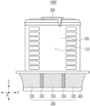
- FIG. 1 is a view illustrating a state in which the CTBA bushing according to the first embodiment is mounted on a CTBA suspension system.
- a CTBA bushing 1000 according to the first embodiment is press-fitted into a bushing bracket 30 provided at a tip of a trailing arm 20 at each of two opposite sides of the CTBA suspension system 10 .
- the CTBA bushing 1000 copes with behavior in a first direction X, which is an upward/downward direction P 2 of a vehicle, a second direction Y, which is a forward/rearward direction P 1 of the vehicle, and a third direction Z which is a leftward/rightward direction Q of the vehicle.
- a bushing rubber of the CTBA bushing 1000 has hardness in the first direction X, which is the upward/downward direction P 2 of the vehicle, lower than hardness in the second direction Y and the third direction Z in order to improve NVH (noise, vibration, and harshness) performance.
- the bushing rubber has hardness in the second direction Y, which is the forward/rearward direction P 1 of the vehicle, higher than hardness in the first direction X and the third direction Z in order to improve ride quality performance.
- the bushing rubber has hardness in the third direction Z, which is between the hardness in the first direction X and the hardness in the second direction Y in order to improve R&H (ride and handling) performance.
- the CTBA bushing 1000 has different degrees of optimal hardness in the first direction X, the second direction Y, and the third direction Z in consideration of behavior characteristics in the first direction X, which is the upward/downward direction P 2 of the vehicle, the second direction Y, which is the forward/rearward direction P 1 of the vehicle, and the third direction Z in the leftward/rightward direction Q of the vehicle, thereby improving the NVH performance, the ride quality performance, and the R&H performance of the vehicle.
- FIG. 2 is a side view illustrating the CTBA bushing according to the first embodiment.
- FIG. 3 is a top plan view illustrating the CTBA bushing according to the first embodiment.
- FIG. 4 is a cross-sectional view taken along line IV-IV in FIG. 3 .
- FIG. 5 is a cross-sectional view taken along line V-V in FIG. 3 .
- the CTBA bushing 1000 includes an outer pipe 100 , an inner pipe 200 , a bushing rubber 300 , and a side stopper 400 .
- the outer pipe 100 includes a through-hole 110 formed therein.
- the outer pipe 100 is press-fitted into the bushing bracket of the CTBA suspension system.
- the outer pipe 100 may have publicly-known various shapes.
- the inner pipe 200 is positioned in the through-hole 110 of the outer pipe 100 .
- the inner pipe 200 is connected to a vehicle body of the vehicle.
- the inner pipe 200 may have publicly-known various shapes.
- the bushing rubber 300 is disposed in the through-hole 110 of the outer pipe 100 and positioned between an outer peripheral surface of the inner pipe 200 and an inner peripheral surface of the outer pipe 100 .
- the bushing rubber 300 has elasticity.
- the bushing rubber 300 in the CTBA suspension system has different degrees of optimal hardness in the first, second and third directions (i.e., X, Y and Z directions), thereby improving the NVH performance, the ride quality performance, and the R&H performance of the vehicle.
- the first direction X is the upward/downward direction of the vehicle
- the second direction Y is the forward/rearward direction of the vehicle
- the third direction Z is the leftward/rightward direction of the vehicle.
- the bushing rubber 300 includes first compounds 310 , second compounds 320 , and third compounds 330 which are integrated with one another.
- the first compounds 310 extend in the first direction X, which is a diameter direction of the inner pipe 200 , with the inner pipe 200 interposed therebetween.
- the first compound 310 is integrated with the second compound 320 and the third compound 330 .
- the first compound 310 may be made of a different material from the second compound 320 and include publicly-known various types of rubber.
- the first compound 310 has lower hardness than the second compound 320 .
- the first compound 310 has lower hardness than the second compound 320 and the third compound 330 , and the first compound 310 in the CTBA suspension system provides a first elastic restoring force in the first direction X which is the upward/downward direction of the vehicle, thereby improving the NVH performance of the vehicle.
- any one of the first compound 310 and the second compound 320 may have at least one of higher elasticity, higher durability, and higher heat resistance than the other compound.
- the second compounds 320 extend in the second direction Y, which is perpendicular to the first direction X, with the inner pipe 200 interposed therebetween.
- the second compound 320 is integrated with the first compound 310 and the third compound 330 .
- the second compound 320 may be made of a different material from the first compound 310 and include publicly-known various types of rubber.
- the second compound 320 has higher hardness than the first compound 310 .
- the second compound 320 has higher hardness than the first compound 310 and the third compound 330 , and the second compound 320 in the CTBA suspension system provides a second elastic restoring force in the second direction Y which is the forward/rearward direction of the vehicle, thereby improving the ride quality performance of the vehicle.
- the second compounds 320 and the first compounds 310 define a cross shape around the inner pipe 200 .
- the second compounds 320 and the first compounds 310 may define, but not limited to, a radial shape around the inner pipe 200 .
- the third compound 330 is positioned between the first compound 310 and the second compound 320 .
- the third compound 330 is made by mixing the first compound 310 and the second compound 320 .
- the third compound 330 is disposed between the first compound 310 and the second compound 320 and integrated with the first compound 310 and the second compound 320 .
- the third compound 330 may be made of a mixture made by mixing the first compound 310 and the second compound 320 and include publicly-known various types of rubber.
- the third compound 330 may have a hardness between the hardness of the first compound 310 and the hardness of the second compound 320 . As illustrated in FIG.
- the third compound 330 extends in a direction perpendicular to the third direction Z that intersects the first direction X and the second direction Y.
- the hardness and a direction of the elastic restoring force of the third compound 330 may be variously adjusted by adjusting a mixing percentage of the first compound 310 and the second compound 320 and a direction in which the third compound 330 extends between the first compound 310 and the second compound 320 .
- the third compound 330 is made by mixing the first compound 310 and the second compound 320 and thus has hardness between the hardness of the first compound 310 and the hardness of the second compound 320 , such that the third compound 330 in the CTBA suspension system provides a third elastic restoring force in the third direction Z which is the leftward/rightward direction of the vehicle, thereby improving the R&H performance of the vehicle.
- the first compound 310 includes a first rubber material having a first hardness
- the second compound 320 includes a second rubber material having a second hardness higher than the first hardness
- the third compound 330 includes a mixture of the first rubber material and the second rubber material and having a third hardness set between the first hardness and the second hardness.
- the first compound 310 , second compound 320 and third compound 330 may be integrated by injecting the first rubber material constituting the first compound 310 into one position corresponding to the first compound 310 in a single mold having a shape of the bushing rubber and simultaneously injecting the second rubber material constituting the second compound 320 into the other position corresponding to the second compound 320 .
- the mold since the first compounds 310 and the second compounds 320 define a cross shape, the mold may be easily separated from the bushing rubber 300 .
- the bushing rubber 300 is not limited to the structure illustrated in FIGS. 2 to 5 and may have publicly-known various structures corresponding to the structure of the vehicle and the structure of the CTBA suspension system as long as the bushing rubber 300 includes the first compound 310 , the second compound 320 , and the third compound 330 which are integrated.
- the bushing rubber 300 may include open or closed holes having various shapes and formed inside or outside, depressed or protruding portions having various shapes, insertion substances having various shapes, and the like.
- One end of the bushing rubber 300 may be exposed to the outside of the outer pipe 100 , but the present disclosure is not limited thereto.
- One end of the bushing rubber 300 may be positioned in the outer pipe 100 .
- the bushing rubber 300 may include a plurality of compounds extending in different directions.
- the plurality of compounds may include, but not limited to, two to twenty compounds.
- the side stopper 400 is positioned at one end of the bushing rubber 300 that is exposed to the outside of the outer pipe 100 .
- the side stopper 400 may inhibit or prevent the bushing rubber 300 from separating from the outer pipe 100 or the inner pipe 200 , but the present disclosure is not limited thereto.
- the CTBA bushing 1000 includes the first compound 310 , the second compound 320 , and the third compound 330 which are integrated with one another. Therefore, the CTBA bushing 1000 in the CTBA suspension system provides the first elastic restoring force corresponding to the first hardness of the first compound 310 in the first direction X which is the upward/downward direction of the vehicle, provides the second elastic restoring force corresponding to the second hardness of the second compound 320 in the second direction Y which is the forward/rearward direction of the vehicle, and provides the third elastic restoring force corresponding to the third hardness of the third compound 330 in the third direction Z which is the leftward/rightward direction of the vehicle, thereby improving the NVH performance, the ride quality performance, and the R&H performance of the vehicle in consideration of behavior characteristics in the upward/downward direction, the forward/rearward direction, and the leftward/rightward direction of the vehicle.
- the present disclosure provides the CTBA bushing 1000 that optimally copes with the behavior characteristics of the vehicle in the upward/downward direction, the forward/rearward direction, and the leftward/rightward direction of the vehicle.
- CTBA bushings according to second to sixth embodiments is described with reference to FIGS. 6 to 10 .
- the parts different from the parts of the CTBA bushing according to the first embodiment are described.
- FIG. 6 is a side view illustrating the CTBA bushing according to the second embodiment.
- a bushing rubber 300 of a CTBA bushing 1002 includes a first compound 310 , second compounds 320 , and third compounds 330 .
- the third compound 330 is positioned between the first compound 310 and the second compound 320 .
- the third compound 330 is made by mixing the first compound 310 and the second compound 320 .
- the third compound 330 is disposed between the first compound 310 and the second compound 320 and integrated with the first compound 310 and the second compound 320 .
- the third compound 330 may be made of a mixture made by mixing the first compound 310 and the second compound 320 and include publicly-known various types of rubber.
- the third compound 330 may have a hardness set between the hardness of the first compound 310 and the hardness of the second compound 320 .
- the third compound 330 extends in a helical or swirl shape in the third direction Z that intersects the first direction X and the second direction Y.
- the direction of hardness and elastic restoring force of the third compound 330 is adjusted by adjusting a direction in which the third compound 330 extends between the first compound 310 and the second compound 320 .
- the direction of hardness and elastic restoring force of the third compound 330 is adjusted to the third direction Z by adjusting the direction in which the third compound 330 extends between the first compound 310 and the second compound 320 , and thus the CTBA bushing in the CTBA suspension system provides an elastic restoring force optimally adjusted in the third direction Z which is the leftward/rightward direction of the vehicle, thereby improving the R&H performance of the vehicle.
- the third compound 330 may extend as a divided structure in the third direction Z that intersects the first direction X and the second direction Y.
- a lower plate of a single mold having a shape of the bushing rubber includes a protruding portion of a swirl structure corresponding to the helical or swirl shape of the third compound 330 . Therefore, the third compound 330 may extend in the helical or swirl shape in the third direction Z while corresponding to the lower plate of the mold when the first rubber material of the first compound 310 and the second rubber material of the second compound 320 are mixed.
- the present disclosure provides the CTBA bushing 1002 that optimally copes with the behavior characteristics of the vehicle in the upward/downward direction, the forward/rearward direction, and the leftward/rightward direction of the vehicle.
- FIG. 7 is a side view illustrating the CTBA bushing according to the third embodiment.
- a bushing rubber 300 of a CTBA bushing 1003 includes a first compound 310 , second compounds 320 , and third compounds 330 .
- the third compound 330 is positioned between the first compound 310 and the second compound 320 .
- the third compound 330 is made by mixing the first compound 310 and the second compound 320 .
- the third compound 330 is disposed between the first compound 310 and the second compound 320 and integrated with the first compound 310 and the second compound 320 .
- the third compound 330 may be made of a mixture made by mixing the first compound 310 and the second compound 320 and include publicly-known various types of rubber.
- the third compound 330 may have a hardness set between the hardness of the first compound 310 and the hardness of the second compound 320 .
- the third compound 330 extends while being inclined leftward with respect to the third direction Z that intersects the first direction X and the second direction Y.
- the direction of hardness and elastic restoring force of the third compound 330 is adjusted by adjusting a direction in which the third compound 330 extends between the first compound 310 and the second compound 320 .
- the direction of hardness and elastic restoring force of the third compound 330 is adjusted to the third direction Z by adjusting the direction in which the third compound 330 extends between the first compound 310 and the second compound 320 , and thus the CTBA bushing in the CTBA suspension system provides an elastic restoring force optimally adjusted in the third direction Z which is the leftward/rightward direction of the vehicle, thereby improving the R&H performance of the vehicle.
- a lower plate of a single mold having a shape of the bushing rubber includes a protruding portion of a leftward structure, such that the third compound 330 may extend while being inclined leftward in the third direction Z while corresponding to the lower plate of the mold when the first rubber material of the first compound 310 and the second rubber material of the second compound 320 are mixed.
- the present disclosure provides the CTBA bushing 1003 that optimally copes with the behavior characteristics of the vehicle in the upward/downward direction, the forward/rearward direction, and the leftward/rightward direction of the vehicle.
- FIG. 8 is a side view illustrating the CTBA bushing according to the fourth embodiment.
- a bushing rubber 300 of a CTBA bushing 1004 includes a first compound 310 , second compounds 320 , and third compounds 330 .
- the third compound 330 is positioned between the first compound 310 and the second compound 320 .
- the third compound 330 is made by mixing the first compound 310 and the second compound 320 .
- the third compound 330 is disposed between the first compound 310 and the second compound 320 and integrated with the first compound 310 and the second compound 320 .
- the third compound 330 may be made of a mixture made by mixing the first compound 310 and the second compound 320 and include publicly-known various types of rubber.
- the third compound 330 may have a hardness set between the hardness of the first compound 310 and the hardness of the second compound 320 .
- the third compound 330 extends while being inclined rightward with respect to the third direction Z that intersects the first direction X and the second direction Y.
- the direction of hardness and elastic restoring force of the third compound 330 is adjusted by adjusting a direction in which the third compound 330 extends between the first compound 310 and the second compound 320 .
- the direction of hardness and elastic restoring force of the third compound 330 is adjusted to the third direction Z by adjusting the direction in which the third compound 330 extends between the first compound 310 and the second compound 320 , and thus the CTBA bushing in the CTBA suspension system provides an elastic restoring force optimally adjusted in the third direction Z which is the leftward/rightward direction of the vehicle, thereby improving the R&H performance of the vehicle.
- a lower plate of a single mold having a shape of the bushing rubber includes a protruding portion of a rightward structure, such that the third compound 330 may extend while being inclined rightward in the third direction Z while corresponding to the lower plate of the mold when the first rubber material of the first compound 310 and the second rubber material of the second compound 320 are mixed.
- the present disclosure provides the CTBA bushing 1004 that optimally copes with the behavior characteristics in the upward/downward direction, the forward/rearward direction, and the leftward/rightward direction of the vehicle.
- FIG. 9 is a longitudinal sectional view illustrating the CTBA bushing according to the fifth embodiment.
- a first compound 310 of a bushing rubber 300 of a CTBA bushing 1005 includes a first sub-compound 311 and a second sub-compound 312 spaced apart from each other with the inner pipe 200 interposed therebetween.
- a hardness of the first sub-compound 311 is different from a hardness of the second sub-compound 312 .
- the hardness of the first sub-compound 311 may be set to be higher than the hardness of the second sub-compound 312 , but the present disclosure is not limited thereto.
- any one of the first sub-compound 311 and the second sub-compound 312 may have at least one of higher elasticity, higher durability, and higher heat resistance than the other compound.
- the CTBA bushing in the CTBA suspension system provides different elastic restoring forces in upward and downward directions of the first direction X which is the upward/downward direction of the vehicle, thereby improving the NVH performance of the vehicle.
- the present disclosure provides the CTBA bushing 1005 that optimally copes with the behavior characteristics of the vehicle in the upward/downward direction, the forward/rearward direction, and the leftward/rightward direction of the vehicle.
- FIG. 10 is a longitudinal sectional view illustrating the CTBA bushing according to the sixth embodiment.
- a second compound 320 of a bushing rubber 300 of a CTBA bushing 1006 includes a third sub-compound 321 and a fourth sub-compound 322 spaced apart from each other with the inner pipe 200 interposed therebetween.
- a hardness of the third sub-compound 321 is different from a hardness of the fourth sub-compound 322 .
- the hardness of the third sub-compound 321 may be set to be higher than the hardness of the fourth sub-compound 322 , but the present disclosure is not limited thereto.
- any one of the third sub-compound 321 and the fourth compound 322 may have at least one of higher elasticity, higher durability, and higher heat resistance than the other compound.
- the CTBA bushing in the CTBA suspension system provides different elastic restoring force in forward and rearward directions in the second direction Y which is the forward/rearward direction of the vehicle, thereby improving the ride quality performance of the vehicle.
- the present disclosure provides the CTBA bushing 1006 that optimally copes with the behavior characteristics of the vehicle in the upward/downward direction, the forward/rearward direction, and the leftward/rightward direction of the vehicle.
Landscapes
- Engineering & Computer Science (AREA)
- Mechanical Engineering (AREA)
- General Engineering & Computer Science (AREA)
- Springs (AREA)
Abstract
Description
Claims (14)
Applications Claiming Priority (2)
| Application Number | Priority Date | Filing Date | Title |
|---|---|---|---|
| KR1020210106569A KR20230024601A (en) | 2021-08-12 | 2021-08-12 | Bush for ctba |
| KR10-2021-0106569 | 2021-08-12 |
Publications (2)
| Publication Number | Publication Date |
|---|---|
| US20230049765A1 US20230049765A1 (en) | 2023-02-16 |
| US11766913B2 true US11766913B2 (en) | 2023-09-26 |
Family
ID=85177598
Family Applications (1)
| Application Number | Title | Priority Date | Filing Date |
|---|---|---|---|
| US17/884,637 Active 2042-08-10 US11766913B2 (en) | 2021-08-12 | 2022-08-10 | Coupled torsion beam axle bushing |
Country Status (3)
| Country | Link |
|---|---|
| US (1) | US11766913B2 (en) |
| KR (1) | KR20230024601A (en) |
| CN (1) | CN115923416A (en) |
Families Citing this family (2)
| Publication number | Priority date | Publication date | Assignee | Title |
|---|---|---|---|---|
| KR20230172296A (en) * | 2022-06-15 | 2023-12-22 | 현대자동차주식회사 | Reinforcing structure of the suspension |
| KR20240072827A (en) * | 2022-11-17 | 2024-05-24 | 현대자동차주식회사 | Rear side member of vehicle |
Citations (17)
| Publication number | Priority date | Publication date | Assignee | Title |
|---|---|---|---|---|
| US5676356A (en) * | 1996-05-30 | 1997-10-14 | The Boler Company | Flexible bolster |
| US20020093170A1 (en) * | 2000-12-22 | 2002-07-18 | Alain Deschaume | Antivibration sleeve and a motor vehicle including such a sleeve |
| CN1723149A (en) * | 2002-12-09 | 2006-01-18 | 洛德公司 | Moving tracks dozer equalizer link elastomeric bearing assembly |
| WO2008119341A1 (en) * | 2007-03-29 | 2008-10-09 | Zf Friedrichshafen Ag | Connector piece for the articulated connection of components located in the suspension of a vehicle |
| KR101315678B1 (en) * | 2012-10-16 | 2013-10-08 | 대원강업주식회사 | Bush for mounting stabilizer bar for vehicle |
| DE202016100149U1 (en) * | 2016-01-14 | 2016-02-29 | Vorwerk Autotec Gmbh & Co.Kg | Bearing for the articulation of a chassis stabilizer on a motor vehicle |
| DE102016114737A1 (en) * | 2016-08-09 | 2018-02-15 | Vibracoustic Gmbh | Bearing bushing and method for producing the bearing bush |
| KR20190005754A (en) * | 2017-07-07 | 2019-01-16 | 젯트에프 프리드리히스하펜 아게 | Method for producing a bearing bush, bearing bush and control arm for a wheel suspension of a motor vehicle |
| US20190389513A1 (en) * | 2018-06-25 | 2019-12-26 | Honda Motor Co., Ltd. | Bracket and mounting system for use in supporting a module within a vehicle |
| DE102019006967A1 (en) * | 2019-10-07 | 2020-04-02 | Daimler Ag | Elastomer bearing |
| US20200108682A1 (en) * | 2018-10-04 | 2020-04-09 | Mazda Motor Corporation | Bushing and vehicle suspension device |
| KR20200065213A (en) * | 2018-11-29 | 2020-06-09 | 현대자동차주식회사 | Stabilizer bar bush for vehicle |
| US20210138859A1 (en) * | 2019-11-08 | 2021-05-13 | Hyundai Motor Company | Void bush for vehicle suspension |
| CN113446341A (en) * | 2020-03-25 | 2021-09-28 | 普尔曼公司 | Bushing for vehicle upper support |
| KR20220083317A (en) * | 2020-12-11 | 2022-06-20 | 르노코리아자동차 주식회사 | Stabilizer bar bush |
| KR20220083318A (en) * | 2020-12-11 | 2022-06-20 | 르노코리아자동차 주식회사 | Stabilizer bar bush |
| US20220332161A1 (en) * | 2021-04-20 | 2022-10-20 | Ford Global Technologies Llc | Semi-Rigid Axle for a Vehicle |
-
2021
- 2021-08-12 KR KR1020210106569A patent/KR20230024601A/en active Pending
-
2022
- 2022-08-10 US US17/884,637 patent/US11766913B2/en active Active
- 2022-08-12 CN CN202210966441.1A patent/CN115923416A/en active Pending
Patent Citations (22)
| Publication number | Priority date | Publication date | Assignee | Title |
|---|---|---|---|---|
| US5676356A (en) * | 1996-05-30 | 1997-10-14 | The Boler Company | Flexible bolster |
| US20020093170A1 (en) * | 2000-12-22 | 2002-07-18 | Alain Deschaume | Antivibration sleeve and a motor vehicle including such a sleeve |
| US6729611B2 (en) * | 2000-12-22 | 2004-05-04 | Hutchinson | Antivibration sleeve and a motor vehicle including such a sleeve |
| CN1723149A (en) * | 2002-12-09 | 2006-01-18 | 洛德公司 | Moving tracks dozer equalizer link elastomeric bearing assembly |
| WO2008119341A1 (en) * | 2007-03-29 | 2008-10-09 | Zf Friedrichshafen Ag | Connector piece for the articulated connection of components located in the suspension of a vehicle |
| KR101315678B1 (en) * | 2012-10-16 | 2013-10-08 | 대원강업주식회사 | Bush for mounting stabilizer bar for vehicle |
| DE202016100149U1 (en) * | 2016-01-14 | 2016-02-29 | Vorwerk Autotec Gmbh & Co.Kg | Bearing for the articulation of a chassis stabilizer on a motor vehicle |
| DE102016114737A1 (en) * | 2016-08-09 | 2018-02-15 | Vibracoustic Gmbh | Bearing bushing and method for producing the bearing bush |
| KR20190005754A (en) * | 2017-07-07 | 2019-01-16 | 젯트에프 프리드리히스하펜 아게 | Method for producing a bearing bush, bearing bush and control arm for a wheel suspension of a motor vehicle |
| US10577024B2 (en) * | 2018-06-25 | 2020-03-03 | Honda Motor Co., Ltd. | Bracket and mounting system for use in supporting a module within a vehicle |
| US20190389513A1 (en) * | 2018-06-25 | 2019-12-26 | Honda Motor Co., Ltd. | Bracket and mounting system for use in supporting a module within a vehicle |
| US20200108682A1 (en) * | 2018-10-04 | 2020-04-09 | Mazda Motor Corporation | Bushing and vehicle suspension device |
| US11433725B2 (en) * | 2018-10-04 | 2022-09-06 | Mazda Motor Corporation | Bushing and vehicle suspension device |
| KR20200065213A (en) * | 2018-11-29 | 2020-06-09 | 현대자동차주식회사 | Stabilizer bar bush for vehicle |
| DE102019006967A1 (en) * | 2019-10-07 | 2020-04-02 | Daimler Ag | Elastomer bearing |
| US20210138859A1 (en) * | 2019-11-08 | 2021-05-13 | Hyundai Motor Company | Void bush for vehicle suspension |
| US11453262B2 (en) * | 2019-11-08 | 2022-09-27 | Hyundai Motor Company | Void bush for vehicle suspension |
| CN113446341A (en) * | 2020-03-25 | 2021-09-28 | 普尔曼公司 | Bushing for vehicle upper support |
| CN113446341B (en) * | 2020-03-25 | 2022-09-23 | 普尔曼公司 | Bushing for vehicle upper support |
| KR20220083317A (en) * | 2020-12-11 | 2022-06-20 | 르노코리아자동차 주식회사 | Stabilizer bar bush |
| KR20220083318A (en) * | 2020-12-11 | 2022-06-20 | 르노코리아자동차 주식회사 | Stabilizer bar bush |
| US20220332161A1 (en) * | 2021-04-20 | 2022-10-20 | Ford Global Technologies Llc | Semi-Rigid Axle for a Vehicle |
Non-Patent Citations (1)
| Title |
|---|
| KR 20200065213 A machine translation from espacenet.com Jan. 2023. * |
Also Published As
| Publication number | Publication date |
|---|---|
| CN115923416A (en) | 2023-04-07 |
| KR20230024601A (en) | 2023-02-21 |
| US20230049765A1 (en) | 2023-02-16 |
Similar Documents
| Publication | Publication Date | Title |
|---|---|---|
| US11766913B2 (en) | Coupled torsion beam axle bushing | |
| JP7140767B2 (en) | Bush arrangement structure | |
| DE102015117337A1 (en) | hydromount | |
| US10208847B1 (en) | Structure of transmission mount | |
| DE102016106948A1 (en) | Stabilizer bush and stabilizer bar attachment device | |
| JP4505748B2 (en) | Anti-vibration rubber device | |
| US7866640B2 (en) | Bush | |
| DE112015006335T5 (en) | suspension device | |
| DE102010036043B4 (en) | The sub-frame support structure | |
| CN115899137A (en) | Vehicle Pillar Insulators | |
| DE102019118416A1 (en) | Vehicle front structure | |
| KR102751058B1 (en) | CTBA Bush and Coupled Torsion Beam Axle Suspension System Thereof | |
| DE102008062780A1 (en) | Twist-beam axle for a vehicle | |
| JP2009001085A (en) | Anti-vibration rubber stopper for railway vehicles | |
| EP2189678B1 (en) | Hydraulic dampening rubber metal bearing | |
| US11572927B2 (en) | Subframe mounting bush structure | |
| EP1577126A1 (en) | Elastomeric mounting | |
| JP2007245890A (en) | Suspension bush and double joint type suspension mechanism using the same | |
| DE102014224602A1 (en) | Elastomeric bearing for a motor vehicle | |
| KR102664095B1 (en) | Transmission mount | |
| CN114251397B (en) | Torque rod | |
| JP3653106B2 (en) | Manufacturing method of resin connecting rod | |
| DE102021114548A1 (en) | Bushing for vehicles and method of assembling the same | |
| JPH0722142U (en) | Cylindrical anti-vibration member | |
| CN214355479U (en) | Device for enhancing rigidity of vehicle body and vehicle thereof |
Legal Events
| Date | Code | Title | Description |
|---|---|---|---|
| AS | Assignment |
Owner name: DAEHEUNG R&T CO., LTD., KOREA, REPUBLIC OF Free format text: ASSIGNMENT OF ASSIGNORS INTEREST;ASSIGNORS:LEE, TAEHEE;SUNG, DAE UN;SONG, JIEUN;AND OTHERS;SIGNING DATES FROM 20220801 TO 20220803;REEL/FRAME:060770/0154 Owner name: KIA CORPORATION, KOREA, REPUBLIC OF Free format text: ASSIGNMENT OF ASSIGNORS INTEREST;ASSIGNORS:LEE, TAEHEE;SUNG, DAE UN;SONG, JIEUN;AND OTHERS;SIGNING DATES FROM 20220801 TO 20220803;REEL/FRAME:060770/0154 Owner name: HYUNDAI MOTOR COMPANY, KOREA, REPUBLIC OF Free format text: ASSIGNMENT OF ASSIGNORS INTEREST;ASSIGNORS:LEE, TAEHEE;SUNG, DAE UN;SONG, JIEUN;AND OTHERS;SIGNING DATES FROM 20220801 TO 20220803;REEL/FRAME:060770/0154 |
|
| FEPP | Fee payment procedure |
Free format text: ENTITY STATUS SET TO UNDISCOUNTED (ORIGINAL EVENT CODE: BIG.); ENTITY STATUS OF PATENT OWNER: LARGE ENTITY |
|
| STPP | Information on status: patent application and granting procedure in general |
Free format text: NOTICE OF ALLOWANCE MAILED -- APPLICATION RECEIVED IN OFFICE OF PUBLICATIONS |
|
| STPP | Information on status: patent application and granting procedure in general |
Free format text: PUBLICATIONS -- ISSUE FEE PAYMENT RECEIVED |
|
| STPP | Information on status: patent application and granting procedure in general |
Free format text: PUBLICATIONS -- ISSUE FEE PAYMENT VERIFIED |
|
| STCF | Information on status: patent grant |
Free format text: PATENTED CASE |