US11759956B2 - Robot system and control method for robot system - Google Patents
Robot system and control method for robot system Download PDFInfo
- Publication number
- US11759956B2 US11759956B2 US17/118,678 US202017118678A US11759956B2 US 11759956 B2 US11759956 B2 US 11759956B2 US 202017118678 A US202017118678 A US 202017118678A US 11759956 B2 US11759956 B2 US 11759956B2
- Authority
- US
- United States
- Prior art keywords
- position information
- processor
- control section
- robot
- robot arm
- Prior art date
- Legal status (The legal status is an assumption and is not a legal conclusion. Google has not performed a legal analysis and makes no representation as to the accuracy of the status listed.)
- Active, expires
Links
Images


Classifications
-
- B—PERFORMING OPERATIONS; TRANSPORTING
- B25—HAND TOOLS; PORTABLE POWER-DRIVEN TOOLS; MANIPULATORS
- B25J—MANIPULATORS; CHAMBERS PROVIDED WITH MANIPULATION DEVICES
- B25J9/00—Programme-controlled manipulators
- B25J9/16—Programme controls
- B25J9/1694—Programme controls characterised by use of sensors other than normal servo-feedback from position, speed or acceleration sensors, perception control, multi-sensor controlled systems, sensor fusion
- B25J9/1697—Vision controlled systems
-
- B—PERFORMING OPERATIONS; TRANSPORTING
- B25—HAND TOOLS; PORTABLE POWER-DRIVEN TOOLS; MANIPULATORS
- B25J—MANIPULATORS; CHAMBERS PROVIDED WITH MANIPULATION DEVICES
- B25J9/00—Programme-controlled manipulators
- B25J9/16—Programme controls
- B25J9/1602—Programme controls characterised by the control system, structure, architecture
-
- B—PERFORMING OPERATIONS; TRANSPORTING
- B25—HAND TOOLS; PORTABLE POWER-DRIVEN TOOLS; MANIPULATORS
- B25J—MANIPULATORS; CHAMBERS PROVIDED WITH MANIPULATION DEVICES
- B25J13/00—Controls for manipulators
- B25J13/08—Controls for manipulators by means of sensing devices, e.g. viewing or touching devices
- B25J13/088—Controls for manipulators by means of sensing devices, e.g. viewing or touching devices with position, velocity or acceleration sensors
-
- B—PERFORMING OPERATIONS; TRANSPORTING
- B25—HAND TOOLS; PORTABLE POWER-DRIVEN TOOLS; MANIPULATORS
- B25J—MANIPULATORS; CHAMBERS PROVIDED WITH MANIPULATION DEVICES
- B25J9/00—Programme-controlled manipulators
- B25J9/10—Programme-controlled manipulators characterised by positioning means for manipulator elements
- B25J9/12—Programme-controlled manipulators characterised by positioning means for manipulator elements electric
-
- B—PERFORMING OPERATIONS; TRANSPORTING
- B25—HAND TOOLS; PORTABLE POWER-DRIVEN TOOLS; MANIPULATORS
- B25J—MANIPULATORS; CHAMBERS PROVIDED WITH MANIPULATION DEVICES
- B25J9/00—Programme-controlled manipulators
- B25J9/16—Programme controls
- B25J9/1628—Programme controls characterised by the control loop
- B25J9/1653—Programme controls characterised by the control loop parameters identification, estimation, stiffness, accuracy, error analysis
-
- G—PHYSICS
- G05—CONTROLLING; REGULATING
- G05B—CONTROL OR REGULATING SYSTEMS IN GENERAL; FUNCTIONAL ELEMENTS OF SUCH SYSTEMS; MONITORING OR TESTING ARRANGEMENTS FOR SUCH SYSTEMS OR ELEMENTS
- G05B19/00—Programme-control systems
- G05B19/02—Programme-control systems electric
- G05B19/04—Programme control other than numerical control, i.e. in sequence controllers or logic controllers
- G05B19/05—Programmable logic controllers, e.g. simulating logic interconnections of signals according to ladder diagrams or function charts
-
- B—PERFORMING OPERATIONS; TRANSPORTING
- B25—HAND TOOLS; PORTABLE POWER-DRIVEN TOOLS; MANIPULATORS
- B25J—MANIPULATORS; CHAMBERS PROVIDED WITH MANIPULATION DEVICES
- B25J9/00—Programme-controlled manipulators
- B25J9/08—Programme-controlled manipulators characterised by modular constructions
-
- G—PHYSICS
- G05—CONTROLLING; REGULATING
- G05B—CONTROL OR REGULATING SYSTEMS IN GENERAL; FUNCTIONAL ELEMENTS OF SUCH SYSTEMS; MONITORING OR TESTING ARRANGEMENTS FOR SUCH SYSTEMS OR ELEMENTS
- G05B2219/00—Program-control systems
- G05B2219/10—Plc systems
- G05B2219/15—Plc structure of the system
- G05B2219/15048—Microprocessor
-
- G—PHYSICS
- G05—CONTROLLING; REGULATING
- G05B—CONTROL OR REGULATING SYSTEMS IN GENERAL; FUNCTIONAL ELEMENTS OF SUCH SYSTEMS; MONITORING OR TESTING ARRANGEMENTS FOR SUCH SYSTEMS OR ELEMENTS
- G05B2219/00—Program-control systems
- G05B2219/30—Nc systems
- G05B2219/34—Director, elements to supervisory
- G05B2219/34359—Real time based interrupt to control axis, other function
-
- G—PHYSICS
- G06—COMPUTING OR CALCULATING; COUNTING
- G06V—IMAGE OR VIDEO RECOGNITION OR UNDERSTANDING
- G06V20/00—Scenes; Scene-specific elements
- G06V20/10—Terrestrial scenes
Definitions
- the present disclosure relates to a robot system and a control method for the robot system.
- JP-A-2018-132829 discloses, as a control device that controls control targets such as machines and equipment, a programmable logic controller including a CPU unit, a power supply unit, and an IO unit.
- the CPU unit includes a microprocessor, a memory, a chip set, and a communication controller including a system timer.
- the system timer generates an interrupt signal at every fixed time interval and provides the interrupt signal to the microprocessor.
- the microprocessor repeatedly executes a control program at a predetermined period using the interrupt signal generated by the system timer to thereby realize operation for controlling a control target.
- the microprocessor and the memory are coupled via the chip set. Therefore, when a control program with a large load is executed in the microprocessor, resources such as the chip set and the memory are sometimes occupied by the control program. At this time, when another program using the interrupt signal accesses the memory via the chip set, acquisition of data from the memory is sometimes delayed. Then, timing when the other program is executed deviates from original timing.
- a robot including a robot arm
- driving of the robot arm is controlled based on position information acquired by an encoder.
- the robot includes a camera.
- a control device processes an image captured by the camera to thereby use the image for driving control for the robot arm. Therefore, the control device of the robot is considered to have the same device configuration as a device configuration of the programmable logic controller described in Patent Literature 1.
- a robot system includes: a robot arm; encoders configured to acquire position information of the robot arm; a first control section configured to execute control processing for controlling operation of the robot arm; and a second control section provided independently from the first control section and configured to transmit a position information request signal for requesting the position information to the encoders.
- the second control section transmits an interrupt signal to the first control section according to the transmission of the position information request signal.
- the first control section executes the control processing based on the interrupt signal and the position information output from the encoders based on the position information request signal.
- a control method for a robot system is a control method for a robot system including: a robot arm; encoders configured to acquire position information of the robot arm; a first control section configured to execute control processing for controlling operation of the robot arm; and a second control section provided independently from the first control section and configured to transmit a position information request signal for requesting the position information to the encoders.
- the control method includes: transmitting, with the second control section, the position information request signal to the encoders and transmitting, with the second control section, an interrupt signal corresponding to the position information request signal to the first control section; and executing the control processing based on the interrupt signal and the position information output from the encoders based on the position information request signal.
- FIG. 1 is a side view showing a robot system according to a first embodiment.
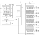
- FIG. 2 is a block diagram of the robot system shown in FIG. 1 .
- FIG. 3 is a diagram showing an example of processing allocated to cores shown in FIG. 2 .
- FIG. 4 is a timing chart in which flows of signals and data between a control device and a robot shown in FIG. 2 are summarized along an elapsed time.
- FIG. 5 is a timing chart in which flows of signals and data between a control device and a robot in related art are summarized along an elapsed time.
- FIG. 6 is a schematic diagram for explaining an abnormality detecting function of a first control section.
- FIG. 7 is a table showing an example of a first control section side axis number and an example of a second control section side axis number corresponding to an interrupt signal received by the first control section.
- FIG. 1 is a side view showing the robot system according to the first embodiment.
- FIG. 2 is a block diagram of the robot system shown in FIG. 1 .
- a robot system 1 shown in FIG. 1 includes a robot 2 and a control device 5 that controls the operation of the robot 2 .
- Uses of the robot system 1 are not particularly limited. Examples of the uses of the robot system 1 include supply, removal, conveyance, and assembly of a precision instrument and components configuring the precision instrument.
- the robot 2 shown in FIG. 1 includes a base 21 , a robot arm 22 coupled to the base 21 , and an imaging section 4 provided in the robot arm 22 .
- the base 21 is fixed to an installation part such as a floor, a wall, a ceiling, or a movable truck.
- the robot arm 22 includes an arm 221 coupled to the base 21 to be capable of turning around a first axis J 1 , an arm 222 coupled to the arm 221 to be capable of turning around a second axis J 2 , an arm 223 coupled to the arm 222 to be capable of turning around a third axis J 3 , an arm 224 coupled to the arm 223 to be capable of turning around a fourth axis J 4 , an arm 225 coupled to the arm 224 to be capable of turning around a fifth axis J 5 , and an arm 226 coupled to the arm 225 to be capable of turning around a sixth axis J 6 .
- An end effector 26 corresponding to work to be executed by the robot 2 is attached to the arm 226 .
- the configuration of the robot 2 is not limited to the configuration in this embodiment.
- the number of arms of the robot arm 22 may be one to five or may be seven or more.
- a type of the robot 2 may be a SCARA robot or a double-arm robot including two robot arms 22 .
- the robot 2 includes, as shown in FIG. 2 , a first driving section 231 , a second driving section 232 , a third driving section 233 , a fourth driving section 234 , a fifth driving section 235 , and a sixth driving section 236 .
- the first driving section 231 includes a not-shown motor that turns the arm 221 with respect to the base 21 and a not-shown speed reducer.
- the second driving section 232 includes a not-shown motor that turns the arm 222 with respect to the arm 221 and a not-shown speed reducer.
- the third driving section 233 includes a not-shown motor that turns the arm 223 with respect to the arm 222 and a not-shown speed reducer.
- the fourth driving section 234 includes a not-shown motor that turns the arm 224 with respect to the arm 223 and a not-shown speed reducer.
- the fifth driving section 235 includes a not-shown motor that turns the arm 225 with respect to the arm 224 and a not-shown speed reducer.
- the sixth driving section 236 includes a not-shown motor that turns the arm 226 with respect to the arm 225 and a not-shown speed reducer.
- the control device 5 controls the operations of the first driving section 231 , the second driving section 232 , the third driving section 233 , the fourth driving section 234 , the fifth driving section 235 , and the sixth driving section 236 to move the arms 221 to 226 to target positions.
- the robot 2 includes encoders 24 that are provided in rotating shafts of the motors or the speed reducers of the driving sections and detect rotation angles of the rotating shafts.
- the encoders 24 acquire position information of the robot arm 22 .
- the position information means information indicating rotation angles of the rotating shafts.
- the encoders 24 have a function of transmitting the acquired position information to the control device 5 for each of the rotating shafts.
- the encoders 24 are multiplexed.
- the multiplexing means making it possible to acquire a plurality of kinds of position information by providing a plurality of encoders for each of the rotating shafts. Therefore, it is possible to impart redundancy to the encoders 24 and more highly accurately detect the positions and the speeds of the rotating shafts.
- the encoders 24 include a first main encoder 241 a , a first sub-encoder 241 b , a second main encoder 242 a , a second sub-encoder 242 b , a third main encoder 243 a , a third sub-encoder 243 b , a fourth main encoder 244 a , a fourth sub-encoder 244 b , a fifth main encoder 245 a , a fifth sub-encoder 245 b , a sixth main encoder 246 a , and a sixth sub-encoder 246 b.
- the first main encoder 241 a and the first sub-encoder 241 b that detect a rotation angle of the rotating shaft of the motor or the speed reducer of the first driving section 231 are provided in the motor or the speed reducer.
- the second main encoder 242 a and the second sub-encoder 242 b that detect a rotation angle of the rotating shaft of the motor or the speed reducer of the second driving section 232 are provided in the motor or the speed reducer.
- the third main encoder 243 a and the third sub-encoder 243 b that detect a rotation angle of the rotating shaft of the motor or the speed reducer of the third driving section 233 are provided in the motor or the speed reducer.
- the fourth main encoder 244 a and the fourth sub-encoder 244 b that detect a rotation angle of the rotating shaft of the motor or the speed reducer of the fourth driving section 234 are provided in the motor or the speed reducer.
- the fifth main encoder 245 a and the fifth sub-encoder 245 b that detect a rotation angle of the rotating shaft of the motor or the speed reducer of the fifth driving section 235 are provided in the motor or the speed reducer.
- the sixth main encoder 246 a and the sixth sub-encoder 246 b that detect a rotation angle of the rotating shaft of the motor or the speed reducer of the sixth driving section 236 are provided in the motor or the speed reducer.
- Examples of the motors include an AC servomotor and a DC servomotor.
- Examples of the speed reducers include a planetary gear-type speed reducer and a wave gear device.
- the motors are electrically coupled to the control device 5 via not-shown motor drivers.
- the encoders 24 are also electrically coupled to the control device 5 .
- the imaging section 4 is attached to the robot arm 22 and images a target of work by the robot 2 and the end effector 26 .
- the imaging section 4 is electrically coupled to the control device 5 .
- the control device 5 is communicably coupled to the robot 2 .
- the control device 5 and the robot 2 may be coupled by wire or may be coupled by radio.
- the control device 5 includes a first control section 51 , a second control section 52 , a system bus 53 , and a main memory 54 .
- the first control section 51 includes a processor such as a CPU (Central Processing Unit) or an MPU (Micro Processing Unit).
- the processor may be a single-core processor that operates in a multi-task manner.
- the processor is preferably a multi-core processor.
- execution of different application programs can be allocated to cores. Consequently, it is possible to smoothly execute the application programs and improve performance, in particular, real-time properties of the control device 5 .
- the first control section 51 shown in FIG. 2 includes a multi-core processor.
- the processor includes a first core 511 , a second core 512 , a third core 513 , and a fourth core 514 .
- the number of cores of the processor is not limited to four.
- FIG. 3 is a diagram showing an example of processing allocated to the cores shown in FIG. 2 .
- the example shown in FIG. 3 is an example in which the multi-core processor used in the first control section 51 is operated by asymmetrical multiprocessing (AMP).
- AMP asymmetrical multiprocessing
- the asymmetrical multiprocessing is a technique for mixing different OSs (Operating Systems) and bare metals on one processor.
- Control processing for the robot 2 including robot arm control processing for controlling the operation of the robot arm 22 is allocated to the first core 511 .
- Image processing is allocated to the second core 512 and the third core 513 .
- Examples of the image processing include imaging processing by the imaging section 4 and filter processing for an obtained image.
- a general-purpose OS such as Linux (registered trademark) is allocated to the first core 511 , the second core 512 , and the third corer 513 . Consequently, it is possible to cause the first core 511 , the second core 512 , and the third core 513 to execute various kinds of general-purpose processing including the processing described above.
- Examples of the general-purpose processing include, besides the image processing, arithmetic operation processing for outputs of a force sensor, a pressure sensor, and a proximity sensor.
- processing concerning an operation position of the robot arm 22 processing concerning operating speed of the robot arm 22 , processing concerning communication with the second control section 52 , and processing concerning other communication are allocated to the fourth core 514 .
- These kinds of processing are respectively processing requested to be executed at a predetermined time interval. Therefore, the processing is referred to as “predetermined interval processing” herein.
- the other communication include processing concerning a field bus and processing concerning a standard input and output.
- the predetermined time interval is not particularly limited but is set to, for example, several ten microseconds to several milliseconds.
- the fourth core 514 is a so-called bare metal to which, for example, an OS is not allocated.
- the bare metal is also called bare metal-type hypervisor and means a virtual environment that makes it possible to directly execute an application program on hardware not via an OS or virtual software for constructing the virtual environment.
- By forming the fourth core 514 as the bare metal it is easier to execute the predetermined interval processing without delay compared with when the general-purpose OS is allocated to the fourth core 514 . That is, it is possible to improve the real-time properties.
- the fourth core 514 is not limited to the bare metal. For example, any OS may be allocated to the fourth core 514 .
- the first control section 51 may include not-shown primary cache memories respectively corresponding to the first core 511 , the second core 512 , the third core 513 , and the fourth core 514 .
- the first control section 51 shown in FIG. 2 includes a secondary cache memory 515 common to the first core 511 , the second core 512 , the third core 513 , and the fourth core 514 .
- the cores and the cores and the secondary cache memory 515 are communicably coupled via not-shown interconnects.
- the first control section 51 may include a not-shown system timer and the like besides the cache memories.
- a hardware configuration of the first control section 51 may be a configuration in which the sections explained above are physically independent from one another but is preferably a configuration in which the sections are integrated in one chip.
- the hardware configuration of the first control section 51 is preferably an SoC (System On Chip). Consequently, it is possible to realize a reduction in the size, power saving, and a reduction in the cost of the first control section 51 .
- the second control section 52 includes elements such as an FPGA (Field-Programmable Gate Array) and an ASIC (Application Specific Integrated Circuit).
- the second control section 52 has a function of generating a timing signal at a predetermined time interval, a function of generating an interrupt signal simultaneously with the timing signal generation and transmitting the interrupt signal to the first control section 51 , and a function of generating a position information request signal simultaneously with the timing signal generation and transmitting the position information request signal to the encoders 24 .
- the second control section 52 is communicably coupled to the first control section 51 via the system bus 53 shown in FIG. 2 .
- the main memory 54 is communicably coupled to the system bus 53 .
- Examples of the main memory 54 include a RAM (Random Access Memory).
- RAM Random Access Memory
- Besides, not-shown various interfaces, a not-shown nonvolatile memory, a not-shown communication controller, and the like may be communicably coupled to the system bus 53 .
- the system bus 53 may be independently configured as a first dedicated bus that couples the first control section 51 and the second control section 52 and a second dedicated bus that couples the first control section 51 and the main memory 54 .
- a software configuration of the control device 5 that is, an operation example of the control device 5 is explained.
- signals and data transmitted and received between the control device 5 and the robot 2 are explained taking, as an example, a process in which the control device 5 acquires position information and speed information from the encoders 24 .
- FIG. 4 is a timing chart in which flows of signals and data between the control device 5 and the robot 2 shown in FIG. 2 are summarized along an elapsed time.
- arrows indicate the flows of the signals and the data.
- Solid line squares indicate processing, operations, or transmission and reception of signals. The arrows connect the solid line squares.
- the horizontal axis of FIG. 4 is a time axis. Time flows from the left to the right.
- a first period is represented as a period t 1 and the next period is represented as a period t 2 .
- the lengths of the periods are equal to one another.
- a processing target axis shown in FIG. 4 indicates a target axis of processing concerning position information executed in a time division manner by the fourth core 514 of the first control section 51 .
- the processing target axis indicates which of the first axis J 1 , the second axis J 2 , the third axis J 3 , the fourth axis J 4 , the fifth axis J 5 , and the sixth axis J 6 the target axis of the processing of the position information by the fourth core 514 of the first control section 51 is in the periods.
- the first to sixth axes J 1 to J 6 are set in order as the processing target axis. The setting of the first to sixth axes J 1 to J 6 is repeated.
- the sections of the control device 5 or the robot 2 are enumerated on the vertical axis of FIG. 4 . Start points and end points of the arrows are respectively located in any one of the sections shown on the vertical axis of FIG. 4 .
- a transmission side of the second control section 52 shown in FIG. 4 indicates, in the second control section 52 , regions for transmitting signals to the sections.
- a reception side of the second control section 52 shown in FIG. 4 indicates, in the second control section 52 , regions for receiving data of position information from the encoders 24 and transmitting the data to the first control section 51 .
- an interrupt signal si 4 is transmitted from the second control section 52 to the first control section 51 based on one timing signal st 4 generated by the second control section 52 .
- the fourth core 514 of the first control section 51 receives the interrupt signal si 4 and executes, with the reception of the interrupt signal si 4 as a trigger, processing concerning the position of the fourth axis J 4 .
- This processing includes acquisition processing pg 4 for acquiring not-shown position information concerning the fourth axis J 4 transmitted from the second control section 52 in a period before the period t 1 and arithmetic operation processing pc 4 for calculating a position and speed of the fourth axis J 4 from the position information.
- the position of the fourth axis J 4 that is, a turning angle from the origin of the fourth axis J 4 is obtained by these kinds of processing. Turning speed of the fourth axis J 4 is obtained based on an amount of change per unit time of the calculated position. Details of the processing are explained below.
- a position information request signal sr 1 is transmitted from the second control section 52 to the first main encoder 241 a and the first sub-encoder 241 b based on one timing signal st 4 generated by the second control section 52 .
- the first main encoder 241 a and the first sub-encoder 241 b respectively receive the position information request signal sr 1 and perform, with the reception of the position information request signal sr 1 as a trigger, a position detecting operation pr 1 for detecting the position of the first axis J 1 . Subsequently, the first main encoder 241 a and the first sub-encoder 241 b transmit, in order, to the second control section 52 , first main position information dm 1 and first sub-position information ds 1 , which are information concerning the position of the first axis J 1 acquired by the position detecting operation pr 1 .
- the second control section 52 receives the first main position information dm 1 and the first sub-position information ds 1 and integrates these kinds of information.
- the second control section 52 saves the integrated information in, for example, the secondary cache memory 515 as first position information d 1 concerning the position and the status of the first axis J 1 .
- the first control section 51 reads out the first position information d 1 .
- the transmission and reception of the various signals and the data do not need to be performed in the period t 1 and may be performed in a period after the period t 1 .
- the transmission of the first main position information dm 1 and the first sub-position information ds 1 and the readout of the first position information d 1 are respectively performed in the period t 2 .
- the first position information d 1 may be saved in the secondary cache memory 515 or may be saved in a not-shown storing section included in the second control section 52 .
- an interrupt signal si 5 is transmitted from the second control section 52 to the first control section 51 based on a timing signal sty generated by the second control section 52 .
- the fourth core 514 of the first control section 51 receives the interrupt signal si 5 and executes, with the reception of the interrupt signal si 5 as a trigger, processing concerning the position of the fifth axis J 5 .
- This processing includes acquisition processing pg 5 for acquiring not-shown position information concerning the fifth axis J 5 transmitted from the second control section 52 in a period before the period t 2 and arithmetic operation processing pc 5 for calculating a position and speed of the fifth axis J 5 from the position information.
- the position of the fifth axis J 5 that is, a turning angle from the origin of the fifth axis J 5 is obtained by these kinds of processing. Turning speed of the fifth axis J 5 is obtained based on an amount of change per unit time of the calculated position. Details of the processing are explained below.
- a position information request signal sr 2 is transmitted from the second control section 52 to the second main encoder 242 a and the second sub-encoder 242 b based on the timing signal sty generated by the second control section 52 .
- the second main encoder 242 a and the second sub-encoder 242 b respectively receive the position information request signal sr 2 and perform, with the reception of the position information request signal sr 2 as a trigger, a position detecting operation pr 2 for detecting the position of the second axis J 2 . Subsequently, the second main encoder 242 a and the second sub-encoder 242 b transmit, in order, to the second control section 52 , second main position information dm 2 and second sub-position information ds 2 , which are information concerning the position of the second axis J 2 acquired by the position detecting operation pr 2 .
- the second control section 52 receives the second main position information dm 2 and the second sub-position information ds 2 and integrates these kinds of information.
- the second control section 52 saves the integrated information in, for example, the secondary cache memory 515 as second position information d 2 concerning the position and the status of the second axis J 2 .
- the first control section 51 reads out the second position information d 2 .
- the transmission and reception of the various signals and the data do not need to be performed in the period t 2 and may be performed in a period after the period t 2 .
- the transmission of the second main position information dm 2 and the second sub-position information ds 2 and the readout of the second position information d 2 are respectively performed in the period t 3 .
- an interrupt signal si 6 is transmitted from the second control section 52 to the first control section 51 based on a timing signal st 6 generated by the second control section 52 .
- the fourth core 514 of the first control section 51 receives the interrupt signal si 6 and executes, with the reception of the interrupt signal si 6 as a trigger, processing concerning the position of the sixth axis J 6 .
- This processing includes acquisition processing pg 6 for acquiring not-shown position information concerning the sixth axis J 6 transmitted from the second control section 52 in a period before the period t 3 and arithmetic operation processing pc 6 for calculating a position and speed of the sixth axis J 6 from the position information.
- the position of the sixth axis J 6 that is, a turning angle from the origin of the sixth axis J 6 is obtained by these kinds of processing. Turning speed of the sixth axis J 6 is obtained based on an amount of change per unit time of the calculated position. Details of the processing are explained below.
- a position information request signal sr 3 is transmitted from the second control section 52 to the third main encoder 243 a and the third sub-encoder 243 b based on the timing signal st 6 generated by the second control section 52 .
- the third main encoder 243 a and the third sub-encoder 243 b respectively receive the position information request signal sr 3 and perform, with the reception of the position information request signal sr 3 as a trigger, a position detecting operation pr 3 for detecting the position of the third axis J 3 . Subsequently, the third main encoder 243 a and the third sub-encoder 243 b transmit, in order, to the second control section 52 , third main position information dm 3 and third sub-position information ds 3 , which are information concerning the position of the third axis J 3 acquired by the position detecting operation pr 3 .
- the second control section 52 receives the third main position information dm 3 and the third sub-position information ds 3 and integrates these kinds of information.
- the second control section 52 saves the integrated information in, for example, the secondary cache memory 515 as third position information d 3 concerning the position and the status of the third axis J 3 .
- the first control section 51 reads out the third position information d 3 .
- the transmission and reception of the various signals and the data do not need to be performed in the period t 3 and may be performed in a period after the period t 3 .
- the transmission of the third main position information dm 3 and the third sub-position information ds 3 and the readout of the third position information d 3 are respectively performed in the period t 4 .
- an interrupt signal si 1 is transmitted from the second control section 52 to the first control section 51 based on a timing signal st 1 generated by the second control section 52 .
- the fourth core 514 of the first control section 51 receives the interrupt signal si 1 and executes, with the reception of the interrupt signal si 1 as a trigger, processing concerning the position of the first axis J 1 .
- This processing includes acquisition processing pg 1 for acquiring the first position information d 1 concerning the first axis J 1 transmitted from the second control section 52 in the period t 1 and arithmetic operation processing pc 1 for calculating a position and speed of the first axis J 1 from the position information.
- the position of the first axis J 1 that is, a turning angle from the origin of the first axis J 1 is obtained by these kinds of processing. Turning speed of the first axis J 1 is obtained based on an amount of change per unit time of the calculated position.
- timing for the execution is determined based on the interrupt signal si 1 as explained above.
- Timing when the first position information d 1 used for these kinds of processing is transmitted to the first control section 51 is determined based on the position information request signal sr 1 transmitted from the second control section 52 in the period t 1 explained above.
- the interrupt signal si 1 is transmitted based on the timing signal st 1 .
- the position information request signal sr 1 is transmitted based on the timing signal st 4 in the period t 1 .
- the timing signals st 1 and st 4 are accurately generated at a predetermined interval in the second control section 52 independent from the first control section 51 . Consequently, the first position information d 1 saved in the secondary cache memory 515 according to the position information request signal sr 1 can be read out by the first control section 51 in the period t 4 .
- the first control section 51 is capable of reading the first position information d 1 necessary for the processing. Consequently, it is unnecessary to separately prepare processing for synchronizing timings of the processing. It is possible to achieve simplification of the configuration of the control device 5 .
- a position information request signal sr 4 is transmitted from the second control section 52 to the fourth main encoder 244 a and the fourth sub-encoder 244 b based on the timing signal st 1 generated by the second control section 52 .
- the fourth main encoder 244 a and the fourth sub-encoder 244 b respectively receive the position information request signal sr 4 and perform, with the reception of the position information request signal sr 4 as a trigger, a position detecting operation pr 4 for detecting the position of the fourth axis J 4 . Subsequently, the fourth main encoder 244 a and the fourth sub-encoder 244 b transmit, in order, to the second control section 52 , fourth main position information dm 4 and fourth sub-position information ds 4 , which are information concerning the position of the fourth axis J 4 acquired by the position detecting operation pr 4 .
- the second control section 52 receives the fourth main position information dm 4 and the fourth sub-position information ds 4 and integrates these kinds of information.
- the second control section 52 saves the integrated information in, for example, the secondary cache memory 515 as fourth position information d 4 concerning the position and the status of the fourth axis J 4 .
- the first control section 51 reads out the fourth position information d 4 .
- the transmission and reception of the various signals and the data do not need to be performed in the period t 4 and may be performed in a period after the period t 4 .
- the transmission of the fourth main position information dm 4 and the fourth sub-position information ds 4 and the readout of the fourth position information d 4 are respectively performed in the period t 5 .
- an interrupt signal si 2 is transmitted from the second control section 52 to the first control section 51 based on a timing signal st 2 generated by the second control section 52 .
- the fourth core 514 of the first control section 51 receives the interrupt signal si 2 and executes, with the reception of the interrupt signal si 2 as a trigger, processing concerning the position of the second axis J 2 .
- This processing includes acquisition processing pg 2 for acquiring the second position information d 2 concerning the second axis J 2 transmitted from the second control section 52 in the period t 2 and arithmetic operation processing pc 2 for calculating a position and speed of the second axis J 2 from the position information.
- the position of the second axis J 2 that is, a turning angle from the origin of the second axis J 2 is obtained by these kinds of processing. Turning speed of the second axis J 2 is obtained based on an amount of change per unit time of the calculated position.
- timing for the execution is determined based on the interrupt signal si 2 as explained above.
- Timing when the second position information d 2 used for these kinds of processing is transmitted to the first control section 51 is determined based on the position information request signal sr 2 transmitted from the second control section 52 in the period t 2 explained above.
- the interrupt signal si 2 is transmitted based on the timing signal st 2 .
- the position information request signal sr 2 is transmitted based on the timing signal st 5 in the period t 2 .
- the timing signals st 2 and st 5 are accurately generated at a predetermined interval in the second control section 52 independent from the first control section 51 . Consequently, the second position information d 2 saved in the secondary cache memory 515 according to the position information request signal sr 2 can be read out by the first control section 51 in the period t 5 .
- the first control section 51 is capable of reading the second position information d 2 necessary for the processing. Consequently, it is unnecessary to separately prepare processing for synchronizing both timings of the processing. It is possible to achieve simplification of the configuration of the control device 5 .
- a position information request signal sr 5 is transmitted from the second control section 52 to the fifth main encoder 245 a and the fifth sub-encoder 245 b based on the timing signal st 2 generated by the second control section 52 .
- the fifth main encoder 245 a and the fifth sub-encoder 245 b respectively receive the position information request signal sr 5 and perform, with the reception of the position information request signal sr 5 as a trigger, a position detecting operation pr 5 for detecting the position of the fifth axis J 5 . Subsequently, the fifth main encoder 245 a and the fifth sub-encoder 245 b transmit, in order, to the second control section 52 , fifth main position information dm 5 and fifth sub-position information ds 5 , which are information concerning the position of the fifth axis J 5 acquired by the position detecting operation pr 5 .
- the second control section 52 receives the fifth main position information dm 5 and the fifth sub-position information ds 5 and integrates these kinds of information.
- the second control section 52 saves the integrated information in, for example, the secondary cache memory 515 as fifth position information d 5 concerning the position and the status of the fifth axis J 5 .
- the first control section 51 reads out the fifth position information d 5 .
- the transmission and reception of the various signals and the data do not need to be performed in the period t 5 and may be performed in a period after the period t 5 .
- the transmission of the fifth main position information dm 5 and the fifth sub-position information ds 5 and the readout of the fifth position information d 5 are respectively performed in the period t 6 .
- an interrupt signal si 3 is transmitted from the second control section 52 to the first control section 51 based on a timing signal st 3 generated by the second control section 52 .
- the fourth core 514 of the first control section 51 receives the interrupt signal si 3 and executes, with the reception of the interrupt signal si 3 as a trigger, processing concerning the position of the third axis J 3 .
- This processing includes acquisition processing pg 3 for acquiring the third position information d 3 concerning the third axis J 3 transmitted from the second control section 52 in the period t 3 and arithmetic operation processing pc 3 for calculating a position and speed of the third axis J 3 from the position information.
- the position of the third axis J 3 that is, a turning angle from the origin of the third axis J 3 is obtained by these kinds of processing. Turning speed of the third axis J 3 is obtained based on an amount of change per unit time of the calculated position.
- timing for the execution is determined based on the interrupt signal si 3 as explained above.
- timing when the third position information d 3 used for these kinds of processing is transmitted to the first control section 51 is determined based on the position information request signal sr 3 transmitted from the second control section 52 in the period t 3 explained above.
- the interrupt signal si 3 is transmitted based on the timing signal st 3 .
- the position information request signal sr 3 is transmitted based on the timing signal st 6 in the period t 3 .
- the timing signals st 3 and st 6 are accurately generated at a predetermined interval in the second control section 52 independent from the first control section 51 . Consequently, the third position information d 3 saved in the secondary cache memory 515 according to the position information request signal sr 3 can be read out by the first control section 51 in the period t 6 .
- the first control section 51 is capable of reading the third position information d 3 necessary for the processing. Consequently, it is unnecessary to separately prepare processing for synchronizing both timings of the processing. It is possible to achieve simplification of the configuration of the control device 5 .
- a position information request signal sr 6 is transmitted from the second control section 52 to the sixth main encoder 246 a and the sixth sub-encoder 246 b based on the timing signal st 3 generated by the second control section 52 .
- the sixth main encoder 246 a and the sixth sub-encoder 246 b respectively receive the position information request signal sr 6 and perform, with the reception of the position information request signal sr 6 as a trigger, a position detecting operation pr 6 for detecting the position of the sixth axis J 6 . Subsequently, the sixth main encoder 246 a and the sixth sub-encoder 246 b transmit, in order, to the second control section 52 , sixth main position information dm 6 and sixth sub-position information ds 6 , which are information concerning the position of the sixth axis J 6 acquired by the position detecting operation pr 6 .
- the second control section 52 receives the sixth main position information dm 6 and the sixth sub-position information ds 6 and integrates these kinds of information.
- the second control section 52 saves the integrated information in, for example, the secondary cache memory 515 as sixth position information d 6 concerning the position and the status of the sixth axis J 6 .
- the first control section 51 reads out the sixth position information d 6 .
- the transmission and reception of the various signals and the data do not need to be performed in the period t 6 and may be performed in a period after the period t 6 .
- the transmission of the sixth main position information dm 6 and the sixth sub-position information ds 6 and the readout of the sixth position information d 6 are respectively performed in a period t 7 .
- control device 5 can acquire positions, speeds, and the like of the first to sixth axes J 1 to J 6 at a predetermined interval.
- the control device 5 is capable of appropriately controlling the operation of the robot arm 22 based on the acquired position, speed, and the like.
- FIG. 5 is a timing chart in which flows of signals and data between a control device and a robot in related art are summarized along an elapsed time.
- the horizontal axis and the vertical axis of FIG. 5 are the same as the horizontal axis and the vertical axis of FIG. 4 .
- the same components as the components shown in FIG. 4 are denoted by the same reference numerals and signs.
- the position information request signals sr 1 , sr 2 , sr 3 , sr 4 , . . . are transmitted from the second control section 52 based on the timing signals st 4 , st 5 , st 6 , st 1 , . . . generated by the second control section 52 .
- a generation period of the timing signals st 4 , st 5 , st 6 , st 1 , . . . is not particularly limited. For example, the generation period is several ten microseconds.
- control signals sc 4 ′, sc 5 ′, sc 6 ′, sc 1 ′, concerning acquisition of position information are transmitted from the first control section 51 instead of these timing signals.
- the second control section 52 which receives the control signals, transmits position information request signals sr 1 ′, sr 2 ′, sr 3 ′, sr 4 ′, . . . to the encoders 24 .
- the timing signals st 4 , sty, st 6 , st 1 , . . . are generated from the second control section 52 .
- the position information request signals sr 1 , sr 2 , sr 3 , sr 4 , . . . are transmitted from the second control section 52 based on the timing signals.
- the control signals sc 4 ′, sc 5 ′, sc 6 ′, sc 1 ′, . . . are transmitted from the first control section 51 to the second control section 52 .
- the position information request signals sr 1 ′, sr 2 ′, sr 3 ′, sr 4 ′, . . . are transmitted from the second control section 52 based on the control signals.
- a transmission interval of the position information request signals sr 1 ′, sr 2 ′, sr 3 ′, sr 4 ′, . . . depends on a transmission interval of the control signals sc 4 ′, sc 5 ′, sc 6 ′, sc 1 ′, . . . .
- Transmission of the control signals sc 4 ′, sc 5 ′, sc 6 ′, sc 1 ′, . . . in the first control section 51 is performed based on the predetermined interval processing in the fourth core 514 . It is assumed that the predetermined interval processing for transmitting the control signals sc 4 ′, sc 5 ′, sc 6 ′, sc 1 ′, . . . is executed immediately before the acquisition processing pg 4 , pg 5 , pg 6 , pg 1 , . . . .
- FIG. 5 showing related art, an example is shown in which a start of the predetermined interval processing for transmitting the control signal sc 4 ′ is delayed in the period t 7 .
- a start of the predetermined interval processing for transmitting the control signal sc 4 ′ is delayed in the period t 7 .
- timing for transmitting the position information request signal sr 1 ′ from the second control section 52 is also delayed.
- a start of the position detecting operation pr 1 for detecting the position of the first axis J 1 is also delayed.
- Transmission of the first main position information dm 1 and the first sub-position information ds 1 and transmission of the first position information d 1 are respectively also delayed.
- the predetermined interval processing in the period t 7 is indicated by dots. Processing and operation affected by the delay are also indicated by dots.
- the first control section 51 calculates speeds from the positions of the axes based on the premise that the position detecting operations pr 1 , pr 2 , pr 3 , pr 4 , . . . are executed at a predetermined time interval.
- the position detecting operations pr 1 , pr 2 , pr 3 , pr 4 , . . . are executed at a predetermined time interval.
- a start of the position detecting operation pr 1 is delayed. This premise is broken. Consequently, accuracy of calculated speed is also deteriorated.
- the position information request signals sr 1 , sr 2 , sr 3 , sr 4 , . . . are transmitted from the second control section 52 based on the timing signals st 4 , st 5 , st 6 , st 1 , . . . generated by the second control section 52 .
- the timing signals st 4 , st 5 , st 6 , and st 1 , . . . are signals generated from the second control section 52 independent from the first control section 51 . Therefore, a generation interval of the timing signals st 4 , st 5 , st 6 , st 1 , . .
- the control device 5 can acquire accurate positions and speeds. That is, in the first control section 51 , even when the secondary cache memory 515 and the system bus 53 are occupied by image processing or the like, the generation interval of the timing signals st 4 , st 5 , st 6 , st 1 , . . . is not affected by the occupation. Therefore, the transmission of the position information request signals sr 1 , sr 2 , sr 3 , sr 4 , . . . transmitted based on the timing signals st 4 , st 5 , st 6 , st 1 , . . . is not delayed irrespective of the state of the first control section 51 . As a result, occurrence of crosstalk of data is prevented and the premise is maintained. Therefore, the control device 5 can acquire accurate positions and speeds.
- a delay of the predetermined interval processing could occur when the secondary cache memory 515 of the first control section 51 and the system bus 53 are occupied by the general-purpose processing.
- FIG. 4 an example is shown in which starts of the acquisition processing pg 4 and the arithmetic operation processing pc 4 are delayed in the period t 7 .
- processing, the starts of which are delayed, is indicated by dots.
- the transmission of the position information request signal sr 1 is not delayed. Accordingly, crosstalk of data is not caused.
- the first control section 51 can acquire normal first position information d 1 . Since the transmission of the position information request signal sr 1 is not delayed, acquisition of normal speed is guaranteed in the control device 5 .
- the control device 5 can execute control processing for accurately controlling the operation of the robot arm 22 based on the positions and the speeds of the axes acquired in this way.
- the robot system 1 includes the robot arm 22 , the encoders 24 that acquire position information of the robot arm 22 , the first control section 51 that executes control processing for controlling the operation of the robot arm 22 , and the second control section 52 that is provided independently from the first control section 51 and transmits the position information request signals sr 1 , sr 2 , sr 3 , sr 4 , . . . for requesting position information to the encoders 24 .
- the second control section 52 transmits the interrupt signal si 4 , si 5 , si 6 , si 1 , . . .
- the first control section 51 executes the control processing based on the interrupt signals si 4 , si 5 , si 6 , si 1 , . . . and the position information output from the encoders 24 based on the position information request signals sr 1 , sr 2 , sr 3 , sr 4 , . . . .
- the control device 5 can acquire an accurate position and accurate speed of the robot arm 22 . Accordingly, the control device 5 can accurately control the operation of the robot arm 22 . That is, in controlling the operation of the robot arm 22 based on the position information acquired from the encoders 24 , even when general-purpose processing with a large load such as image processing is executed in the first control section 51 , it is possible to realize the robot system 1 capable of suppressing deterioration in operation accuracy.
- the second control section 52 being independent from the first control section 51 indicates a state in which the first control section 51 and the second control section 52 do not share a cache memory or a memory replacing the cache memory. Therefore, the first control section 51 and the second control section 52 may be elements separate from each other or may be integrated in one chip.
- the robot system 1 shown in FIG. 2 includes the imaging section 4 .
- the first control section 51 is configured to execute image processing for an image acquired by the imaging section 4 .
- image processing is processing that occupies the secondary cache memory 515 and the system bus 53 at a high occupancy ratio. The effects explained above are particularly significant in the control device 5 in which such processing is executed.
- the encoders 24 shown in FIG. 2 are multiplexed as explained above. Consequently, it is possible to impart redundancy to the encoders 24 and highly accurately detect the positions and the speeds of the rotating shafts obtained based on the position information acquired from the encoders 24 .
- the second control section 52 is configured to repeat the transmission of the position information request signals sr 1 , sr 2 , sr 3 , sr 4 , . . . at the predetermined interval. If the predetermined interval is known in advance, it is possible to calculate turning speeds of the axes in the first control section 51 based on the position information acquired from the encoders 24 . That is, since the turning speeds can be calculated even if time information is not included in the position information, it is possible to achieve simplification of the configuration of the control device 5 .
- a control method for the robot system 1 is a method of controlling the robot system 1 including the robot arm 22 , the encoders 24 that acquire position information of the robot arm 22 , the first control section 51 that executes control processing for controlling the operation of the robot arm 22 , and the second control section 52 that is provided independently from the first control section 51 and transmits the position information request signals sr 1 , sr 2 , sr 3 , sr 4 , . . . for requesting position information to the encoders 24 .
- the control method includes a step of transmitting, with the second control section 52 , the position information request signals sr 1 , sr 2 , sr 3 , sr 4 , . . . to the encoders 24 and transmitting, with the second control section 52 , the interrupt signals si 4 , si 5 , si 6 , si 1 , . . . corresponding to the position information request signals sr 1 , sr 2 , sr 3 , sr 4 , . . . to the first control section 51 and a step of executing, with the first control section 51 , control processing based on the interrupt signals si 4 , si 5 , si 6 , si 1 , . . . and position information output from the encoders 24 based on the position information request signals sr 1 , sr 2 , sr 3 , sr 4 , . . . .
- the control device 5 of the robot system 1 can acquire an accurate position and accurate speed of the robot arm 22 . Accordingly, the control device 5 can accurately control the operation of the robot arm 22 . In controlling the operation of the robot arm 22 based on the position information acquired from the encoders 24 , even when general-purpose processing with a large load such as image processing is executed in the first control section 51 , it is possible to suppress deterioration in operation accuracy.
- the first control section 51 may have an abnormality detecting function of detecting whether the interrupt signals si 4 , si 5 , si 6 , si 1 , . . . transmitted to the first control section 51 by the second control section 52 are normally transmitted and received.
- FIG. 6 is a schematic diagram for explaining the abnormality detecting function of the first control section 51 .
- FIG. 6 is a diagram schematically showing a signal waveform of the interrupt signals si 4 , si 5 , si 6 , si 1 , . . . transmitted from the second control section 52 to the first control section 51 and flows of axial information request signal sa and axial information da.
- the first control section 51 receives the interrupt signals si 4 , si 5 , si 6 , si 1 , . . . generated at a predetermined cycle shown in FIG. 6 and executes, with the reception of the signals as a trigger, the acquisition processing pg 4 , pg 5 , pg 6 , pg 1 , . . . and the arithmetic operation processing pc 4 , pc 5 , pc 6 , and pc 1 , . . . explained above.
- the first control section 51 has a function of counting the number of received interrupt signals and collating the number with a known number of axes to thereby specify information concerning which axis the position information acquired by the first control section 51 in the acquisition processing is.
- first control section side axis number An axis number specified on the inside of the first control section 51 in this way is referred to as “first control section side axis number”.
- the axis number is 1 in the case of the first axis J 1 and is 2 in the case of the second axis J 2 .
- the first control section 51 shown in FIG. 6 requests the second control section 52 to transmit information concerning the axes. That is, the first control section 51 has a function of transmitting the axial information request signal sa.
- the second control section 52 shown in FIG. 6 has a function of returning the axial information da to the first control section 51 based on the axial information request signal sa.
- the second control section 52 has a function of counting the number of transmitted interrupt signals and collating the number with a known number of axes to thereby specify the axial information da.
- the second control section 52 returns an axis number specified on the inside of the second control section 52 to the first control section 51 as the axial information da.
- the transmission of the axial information request signal sa and the return of the axial information da are repeated at a predetermined interval according to the interrupt signals si 4 , si 5 , si 6 , si 1 , . . . .
- the axis number based on the axial information da returned from the second control section 52 in this way is referred to as “second control section side axis number” herein.
- FIG. 7 is a table showing an example of the first control section side axis number and the second control section side axis number corresponding to the interrupt signals si 1 , si 2 , and si 3 received by the first control section 51 .
- FIG. 7 three tables divided into a table at a normal time when the interrupt signals si 1 , si 2 , and si 3 are normally transmitted and received, a table at a noise occurrence time, and a table at a missing occurrence time are shown.
- the first control section 51 acquires the first position information d 1 , the second position information d 2 , and the third position information d 3 through the acquisition processing pg 1 , pg 2 , and pg 3 . Therefore, at the normal time, the first control section side axis number is 1 , 2 , and 3 and the second control section side axis number is also 1 , 2 , and 3 .
- the first control section 51 collates the first control section side axis number and the second control section side axis number and, when the first control section side axis number and the second control section side axis number coincide, detects that transmission and reception of the interrupt signal si 4 , si 5 , si 6 , si 1 , . . . is normal.
- Noise means an abnormal signal that could be misrecognized as the interrupt signals si 1 , si 2 , and si 3 .
- an abnormal signal sx is mixed between the interrupt signal si 2 and the interrupt signal si 3 .
- the first control section 51 When receiving the abnormal signal sx, the first control section 51 misrecognizes the abnormal signal sx as the original interrupt signal si 3 . Accordingly, the first control section side axis number corresponding to the abnormal signal sx is 3 . On the other hand, since the second control section 52 does not transmit the interrupt signal si 3 yet at this point in time, the second control section side axis number is still 2 . Then, the first control section 51 detects a mismatch of the first control section side axis number and the second control section side axis number. Specifically, a magnitude relation indicating the first control section side axis number>the second control section side axis number is detected. When detecting such a mismatch, the first control section 51 determines that the abnormal signal sx is noise. When determining in this way, the first control section 51 does not perform processing executed with reception of an interrupt signal as a trigger. Consequently, it is possible to avoid starts of acquisition processing and arithmetic operation processing at wrong timings.
- Missing means that at least one of the interrupt signals si 1 , si 2 , and si 3 cannot be received.
- FIG. 7 an example is shown in which, although the second control section 52 transmits the interrupt signals si 1 , si 2 , and si 3 , the first control section 51 cannot receive only the interrupt signal si 2 .
- the first control section side axis number at timing when the interrupt signal si 2 is originally received is still 1 .
- the second control section side axis number is 2 .
- the first control section side axis number at timing for receiving the interrupt signal si 3 is 2 .
- the second control section side axis number is 3 .
- the first control section 51 detects mismatch of the first control section side axis number and the second control section side axis number. Specifically, a magnitude relation indicating the first control section side axis number ⁇ the second control section side axis number is detected. When detecting such a mismatch, the first control section 51 determines that missing of the interrupt signal si 2 has occurred. When determining in this way, the first control section 51 only has to perform processing for adding one to the first control section side axis number to match the first control section side axis number and the second control section side axis number.
- the robot arm 22 includes the plurality of arms 221 to 226 .
- the robot system 1 includes the encoders 24 respectively corresponding to the arms 221 to 226 .
- the first control section 51 has a function of executing comparison processing for comparing the first control section side axis number, which is first individual information, held by the first control section 51 according to the interrupt signals si 1 , si 2 , and si 3 , and the second control section side axis number, which is second individual information requested and acquired from the second control section 52 according to the interrupt signals si 1 , si 2 , and si 3 .
- the robot system 1 may stop the operation of the robot system 1 .
- the first control section 51 may have a function of outputting an abnormal signal when the first control section side axis number, which is the first individual information, and the second control section side axis number, which is the second individual information, are different a predetermined number of times or more as a result of the comparison processing. Consequently, the control device 5 can stop the operation of the robot system 1 based on the abnormal signal. As a result, it is possible to improve safety of the robot system 1 .
- the output of the abnormal signal may be performed in both of or may be performed in one of the case in which noise is mixed in the interrupt signals si 1 , si 2 , and si 3 and the case in which missing occurs in the interrupt signals si 1 , si 2 , and si 3 .
- the predetermined number of times is not particularly limited but is set to, for example, three times or more.
- the robot system and the control method for the robot system according to the present disclosure are explained above based on the illustrated embodiment.
- the present disclosure is not limited to this.
- the components of the sections can be replaced with any components having the same functions. Any other components may be added to the embodiment.
Landscapes
- Engineering & Computer Science (AREA)
- Robotics (AREA)
- Mechanical Engineering (AREA)
- Automation & Control Theory (AREA)
- Human Computer Interaction (AREA)
- Physics & Mathematics (AREA)
- General Physics & Mathematics (AREA)
- Manipulator (AREA)
- Numerical Control (AREA)
Abstract
Description
Claims (5)
Applications Claiming Priority (2)
| Application Number | Priority Date | Filing Date | Title |
|---|---|---|---|
| JP2019224689A JP7443740B2 (en) | 2019-12-12 | 2019-12-12 | Robot system and robot system control method |
| JP2019-224689 | 2019-12-12 |
Publications (2)
| Publication Number | Publication Date |
|---|---|
| US20210178602A1 US20210178602A1 (en) | 2021-06-17 |
| US11759956B2 true US11759956B2 (en) | 2023-09-19 |
Family
ID=73793144
Family Applications (1)
| Application Number | Title | Priority Date | Filing Date |
|---|---|---|---|
| US17/118,678 Active 2041-06-16 US11759956B2 (en) | 2019-12-12 | 2020-12-11 | Robot system and control method for robot system |
Country Status (4)
| Country | Link |
|---|---|
| US (1) | US11759956B2 (en) |
| EP (1) | EP3835003A1 (en) |
| JP (1) | JP7443740B2 (en) |
| CN (1) | CN112975949B (en) |
Families Citing this family (2)
| Publication number | Priority date | Publication date | Assignee | Title |
|---|---|---|---|---|
| CN114851203B (en) * | 2022-05-27 | 2024-09-27 | 广东美的白色家电技术创新中心有限公司 | Control circuit and control method of joint module and robot |
| CN119347821B (en) * | 2024-10-16 | 2026-01-30 | 库卡机器人(广东)有限公司 | Robot controllers and robots |
Citations (8)
| Publication number | Priority date | Publication date | Assignee | Title |
|---|---|---|---|---|
| JPH04295902A (en) | 1991-03-25 | 1992-10-20 | Meiki Co Ltd | Controller for injection molding machine |
| JPH09244713A (en) | 1996-03-06 | 1997-09-19 | Matsushita Electric Works Ltd | Programmable controller |
| JP2000339009A (en) | 1999-05-31 | 2000-12-08 | Omron Corp | Positioning control unit, CPU unit, and programmable controller system |
| JP2002082703A (en) | 2000-09-07 | 2002-03-22 | Ryosuke Hosoya | Equipment with medium conveyance system, and method and device for its control |
| US20020068994A1 (en) * | 2000-12-06 | 2002-06-06 | Samsung Electronics Co., Ltd. | Robot control system and method |
| US20160240077A1 (en) * | 2013-10-09 | 2016-08-18 | Fuji Machine Mfg. Co., Ltd. | Multiplexing communication system and working robot |
| JP2018132829A (en) | 2017-02-13 | 2018-08-23 | オムロン株式会社 | Control device |
| US20200047344A1 (en) * | 2016-10-24 | 2020-02-13 | Panasonic Intellectual Property Management Co., Ltd. | Method and device for detecting abnormality of encoder, and robot control system |
Family Cites Families (3)
| Publication number | Priority date | Publication date | Assignee | Title |
|---|---|---|---|---|
| JP6194583B2 (en) * | 2012-01-31 | 2017-09-13 | 株式会社リコー | MOTOR CONTROL DEVICE, MOTOR CONTROL METHOD, MOTOR SYSTEM, CONVEYING DEVICE, AND IMAGE FORMING DEVICE |
| FR3054468B1 (en) * | 2016-07-29 | 2018-08-31 | Staubli Faverges | METHOD FOR CONTROLLING A ROBOT FOR INDUSTRIAL USE |
| CN109109018B (en) * | 2018-09-13 | 2021-09-14 | 上海微创医疗机器人(集团)股份有限公司 | Device and method for detecting working state of sensing equipment on mechanical arm, mechanical arm and medical robot |
-
2019
- 2019-12-12 JP JP2019224689A patent/JP7443740B2/en active Active
-
2020
- 2020-12-10 EP EP20213205.6A patent/EP3835003A1/en active Pending
- 2020-12-11 CN CN202011444494.4A patent/CN112975949B/en active Active
- 2020-12-11 US US17/118,678 patent/US11759956B2/en active Active
Patent Citations (9)
| Publication number | Priority date | Publication date | Assignee | Title |
|---|---|---|---|---|
| JPH04295902A (en) | 1991-03-25 | 1992-10-20 | Meiki Co Ltd | Controller for injection molding machine |
| JPH09244713A (en) | 1996-03-06 | 1997-09-19 | Matsushita Electric Works Ltd | Programmable controller |
| JP2000339009A (en) | 1999-05-31 | 2000-12-08 | Omron Corp | Positioning control unit, CPU unit, and programmable controller system |
| JP2002082703A (en) | 2000-09-07 | 2002-03-22 | Ryosuke Hosoya | Equipment with medium conveyance system, and method and device for its control |
| US20020068994A1 (en) * | 2000-12-06 | 2002-06-06 | Samsung Electronics Co., Ltd. | Robot control system and method |
| US20160240077A1 (en) * | 2013-10-09 | 2016-08-18 | Fuji Machine Mfg. Co., Ltd. | Multiplexing communication system and working robot |
| US20200047344A1 (en) * | 2016-10-24 | 2020-02-13 | Panasonic Intellectual Property Management Co., Ltd. | Method and device for detecting abnormality of encoder, and robot control system |
| JP2018132829A (en) | 2017-02-13 | 2018-08-23 | オムロン株式会社 | Control device |
| US20190369587A1 (en) | 2017-02-13 | 2019-12-05 | Omron Corporation | Control device |
Non-Patent Citations (2)
| Title |
|---|
| D. Bar-On, D. Gershon, A. Israeli and G. Zuniga, "Track II: A multi-processor robot controller," 1993 CompEuro Proceedings Computers in Design, Manufacturing, and Production, 1993, pp. 86-93, doi: 10.1109/CMPEUR.1993.289817. (Year: 1993). * |
| E. Paljug and Xiaoping Yun, "Experimental study of two robot arms manipulating large objects," in IEEE Transactions on Control Systems Technology, vol. 3, No. 2, pp. 177-188, Jun. 1995, doi: 10.1109/87.388126. (Year: 1995). * |
Also Published As
| Publication number | Publication date |
|---|---|
| CN112975949A (en) | 2021-06-18 |
| EP3835003A1 (en) | 2021-06-16 |
| US20210178602A1 (en) | 2021-06-17 |
| JP7443740B2 (en) | 2024-03-06 |
| CN112975949B (en) | 2024-01-16 |
| JP2021091069A (en) | 2021-06-17 |
Similar Documents
| Publication | Publication Date | Title |
|---|---|---|
| US11759956B2 (en) | Robot system and control method for robot system | |
| US10274936B2 (en) | Control apparatus | |
| US10761515B2 (en) | Control system for controlling control object and control device for linking control applications in control system | |
| US8190941B2 (en) | Field control system | |
| JP5494255B2 (en) | Safety control system | |
| JPWO2009130759A1 (en) | Numerical control method and apparatus | |
| US20170075334A1 (en) | Controller | |
| US20150066434A1 (en) | Data acquisition device for acquiring cause of stoppage of drive axis and information relating thereto | |
| US7532637B2 (en) | Synchronous controller | |
| US9886025B2 (en) | Numerical controller with an I/O control unit that generates control information using a processor of the I/O control unit | |
| US10890888B2 (en) | Control apparatus, control program, control system, and control method | |
| US10156836B2 (en) | Programmable logic controller | |
| US10899362B2 (en) | Communication apparatus and communication system | |
| KR20200101682A (en) | Electronic device and control method thereof | |
| US9335757B2 (en) | Numerical controller with auxiliary command execution function | |
| US9880525B2 (en) | Positioning apparatus and PLC system using same | |
| JP5837146B1 (en) | Numerical control system with reduced external input signal capture time | |
| US20230294286A1 (en) | Robot Controller And Robot System | |
| US20220203528A1 (en) | Robot System | |
| CN110320525B (en) | Cooperative distance measurement method and system for multiple optical distance measurement devices | |
| EP3875213A1 (en) | Screw length determination system, screw-tightening system and program | |
| US20110055446A1 (en) | Semiconductor integrated circuit device | |
| JP2025158813A (en) | Vehicle control device | |
| JP4956090B2 (en) | Control information transmission system | |
| CN111555664A (en) | Motor control system and method |
Legal Events
| Date | Code | Title | Description |
|---|---|---|---|
| AS | Assignment |
Owner name: SEIKO EPSON CORPORATION, JAPAN Free format text: ASSIGNMENT OF ASSIGNORS INTEREST;ASSIGNORS:MIZUOCHI, SHUNICHI;OGASAWARA, NAOKI;REEL/FRAME:054613/0431 Effective date: 20200911 |
|
| FEPP | Fee payment procedure |
Free format text: ENTITY STATUS SET TO UNDISCOUNTED (ORIGINAL EVENT CODE: BIG.); ENTITY STATUS OF PATENT OWNER: LARGE ENTITY |
|
| STPP | Information on status: patent application and granting procedure in general |
Free format text: APPLICATION DISPATCHED FROM PREEXAM, NOT YET DOCKETED |
|
| STPP | Information on status: patent application and granting procedure in general |
Free format text: DOCKETED NEW CASE - READY FOR EXAMINATION |
|
| STPP | Information on status: patent application and granting procedure in general |
Free format text: NON FINAL ACTION MAILED |
|
| STPP | Information on status: patent application and granting procedure in general |
Free format text: RESPONSE TO NON-FINAL OFFICE ACTION ENTERED AND FORWARDED TO EXAMINER |
|
| STPP | Information on status: patent application and granting procedure in general |
Free format text: FINAL REJECTION MAILED |
|
| STPP | Information on status: patent application and granting procedure in general |
Free format text: NOTICE OF ALLOWANCE MAILED -- APPLICATION RECEIVED IN OFFICE OF PUBLICATIONS |
|
| STPP | Information on status: patent application and granting procedure in general |
Free format text: PUBLICATIONS -- ISSUE FEE PAYMENT VERIFIED |
|
| STCF | Information on status: patent grant |
Free format text: PATENTED CASE |