US11756181B2 - Method for performing image processing for determining image defect in mixed-color test image through image reading - Google Patents
Method for performing image processing for determining image defect in mixed-color test image through image reading Download PDFInfo
- Publication number
- US11756181B2 US11756181B2 US17/558,496 US202117558496A US11756181B2 US 11756181 B2 US11756181 B2 US 11756181B2 US 202117558496 A US202117558496 A US 202117558496A US 11756181 B2 US11756181 B2 US 11756181B2
- Authority
- US
- United States
- Prior art keywords
- image
- feature
- test
- singular
- test image
- Prior art date
- Legal status (The legal status is an assumption and is not a legal conclusion. Google has not performed a legal analysis and makes no representation as to the accuracy of the status listed.)
- Active, expires
Links
Images


Classifications
-
- G—PHYSICS
- G06—COMPUTING; CALCULATING OR COUNTING
- G06T—IMAGE DATA PROCESSING OR GENERATION, IN GENERAL
- G06T7/00—Image analysis
- G06T7/0002—Inspection of images, e.g. flaw detection
- G06T7/0004—Industrial image inspection
-
- G—PHYSICS
- G06—COMPUTING; CALCULATING OR COUNTING
- G06K—GRAPHICAL DATA READING; PRESENTATION OF DATA; RECORD CARRIERS; HANDLING RECORD CARRIERS
- G06K15/00—Arrangements for producing a permanent visual presentation of the output data, e.g. computer output printers
- G06K15/02—Arrangements for producing a permanent visual presentation of the output data, e.g. computer output printers using printers
- G06K15/027—Test patterns and calibration
-
- G—PHYSICS
- G06—COMPUTING; CALCULATING OR COUNTING
- G06T—IMAGE DATA PROCESSING OR GENERATION, IN GENERAL
- G06T2207/00—Indexing scheme for image analysis or image enhancement
- G06T2207/10—Image acquisition modality
- G06T2207/10004—Still image; Photographic image
- G06T2207/10008—Still image; Photographic image from scanner, fax or copier
-
- G—PHYSICS
- G06—COMPUTING; CALCULATING OR COUNTING
- G06T—IMAGE DATA PROCESSING OR GENERATION, IN GENERAL
- G06T2207/00—Indexing scheme for image analysis or image enhancement
- G06T2207/10—Image acquisition modality
- G06T2207/10024—Color image
-
- G—PHYSICS
- G06—COMPUTING; CALCULATING OR COUNTING
- G06T—IMAGE DATA PROCESSING OR GENERATION, IN GENERAL
- G06T2207/00—Indexing scheme for image analysis or image enhancement
- G06T2207/30—Subject of image; Context of image processing
- G06T2207/30108—Industrial image inspection
- G06T2207/30144—Printing quality
Definitions
- the present disclosure relates to an image processing method and an image processing apparatus for determining the cause of image defects on the basis of a test image.
- An image forming apparatus such as a printer or a multifunction peripheral executes a print process of forming images on sheets.
- image defects such as vertical lines, horizontal lines, spots, and density unevenness may occur in the images formed on output sheets.
- the image defects can be caused by various portions including photoconductors, charging portions, developing portions, and transfer portions.
- the determination of the cause of the image defects requires skill and experience.
- the cause of vertical lines serving as an example of the image defects and feature information including the color, density, or number of screen lines of the vertical lines are associated with each other in advance in table data to identify the cause of the vertical lines on the basis of the table data and the information about the color, density, or number of screen lines of the vertical lines in a test image.
- the table data includes the range of the parameter such as the color, density, or number of screen lines of the images set as a threshold for each type of cause of the vertical lines.
- An image processing method is a method performed by a processor for determining an image defect in a test image obtained through an image reading process performed on an output sheet output by an image forming apparatus.
- the image processing method includes deriving, by the processor, a vertical data string that is composed of data about horizontal representative values serving as representative values of a plurality of pixel values in each line in a horizontal direction in the test image.
- the image processing method further includes determining, by the processor, presence or absence of at least one periodicity set in advance in the vertical data string by performing frequency analysis on the vertical data string.
- the image processing method further includes determining, by the processor, occurrence or non-occurrence and cause of periodic density unevenness serving as a type of the image defect according to a determination result on the periodicity.
- An image processing apparatus includes a processor that executes processes of the image processing method.
- FIG. 1 is a configuration diagram of an image processing apparatus according to an embodiment.
- FIG. 2 is a block diagram showing a configuration of a data processing portion in the image processing apparatus according to the embodiment.
- FIG. 3 is a flowchart showing an example of a procedure of an image-defect determination process in the image processing apparatus according to the embodiment.
- FIG. 4 is a flowchart showing an example of a procedure of a singular-defect determination process in the image processing apparatus according to the embodiment.
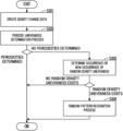
- FIG. 5 is a flowchart showing an example of a procedure of a density-unevenness determination process in the image processing apparatus according to the embodiment.
- FIG. 6 shows an example of a test image including singular portions and examples of preprocessed images and feature images created on the basis of the test image.
- FIG. 7 shows an example of an area of interest and the adjacent areas, the area of interest being sequentially selected from the test image in a main filtering process by the image processing apparatus according to the embodiment.
- FIG. 8 shows an example of a test image including periodic density unevenness and vertical waveform data derived from the test image.
- FIG. 9 is a flowchart showing an example of a procedure of a feature-image creation process in a first application example of the image processing apparatus according to the embodiment.
- the image processing apparatus 10 further includes an image reading apparatus 1 that executes a reading process of reading images from document sheets.
- the image processing apparatus 10 is a copier, a facsimile apparatus, a multifunction peripheral, or the like.
- Images subjected to the print process are those read from the document sheets by the image reading apparatus 1 or those represented by print data received from a host device (not shown).
- the host device is an information processing apparatus such as a personal computer, a personal digital assistant, or the like.
- the image forming apparatus 2 may form an original test image g 01 set in advance by the print process on the sheets (see FIG. 6 ).
- the original test image g 01 is an original image of a test image g 1 used to determine the presence or absence and the cause of image defects in the image forming apparatus 2 (see FIG. 6 ).
- the test image g 1 will be described later.
- a copy process includes the reading process by the image reading apparatus 1 and the print process by the image forming apparatus 2 based on images obtained by the reading process.
- the image forming apparatus 2 includes a sheet conveying mechanism 3 and a print portion 4 .
- the sheet conveying mechanism 3 includes a sheet feed mechanism 31 and pairs of sheet conveying rollers 32 .
- the sheet feed mechanism 31 feeds the sheets from a sheet storing portion 21 to a sheet conveyance path 30 .
- the pairs of sheet conveying rollers 32 convey the sheets along the sheet conveyance path 30 and discharge the sheets with images formed thereon to an output tray 22 .
- the print portion 4 executes the print process on the sheets conveyed by the sheet conveying mechanism 3 .
- the print portion 4 executes the print process by an electrophotographic method.
- the print portion 4 includes imaging portions 4 x , a laser scanning unit 4 y , a transfer device 44 , and a fixing device 46 .
- the imaging portions 4 x each include a drum-like photoconductor 41 , a charging device 42 , a developing device 43 , and a drum cleaning device 45 .
- the photoconductor 41 rotates, and the charging device 42 electrically charges the surface of the photoconductor 41 uniformly.
- the charging device 42 includes a charging roller 42 a that rotates while being in contact with the surface of the photoconductor 41 .
- the charging roller 42 a to which a charging voltage is applied electrically charges the surface of the photoconductor 41 .
- the laser scanning unit 4 y scans laser beams to draw electrostatic latent images on the charged surfaces of the photoconductors 41 . This forms the electrostatic latent images on the surfaces of the photoconductors 41 .
- the developing devices 43 develop the electrostatic latent images as toner images.
- the developing devices 43 each include a developing roller 43 a that supplies toner to the corresponding photoconductor 41 to develop the electrostatic latent images as the toner images.
- the transfer device 44 transfers the toner images from the surfaces of the photoconductors 41 to the sheets. It is noted that the toner is an example of a particulate developer.
- the fixing device 46 fixes the toner images on the sheets to the sheets by heating the toner images.
- the fixing device 46 includes a fixing rotor 46 a brought into contact with the sheets to rotate and a fixing heater 46 b that heats the fixing rotor 46 a.
- the image forming apparatus 2 shown in FIG. 1 is a color printing apparatus of a tandem type and can execute the print process to form color images.
- the print portion 4 includes the four imaging portions 4 x that respectively correspond to toner of different colors.
- the transfer device 44 in the image forming apparatus 2 of the tandem type includes four primary transfer rollers 441 that respectively correspond to the four photoconductors 41 , an intermediate transfer belt 440 , a secondary transfer roller 442 , and a belt cleaning device 443 .
- the four imaging portions 4 x each form the toner images of cyan, magenta, yellow, or black on the surface of the corresponding photoconductor 41 .
- Each of the primary transfer rollers 441 is also part of the corresponding imaging portion 4 x.
- the primary transfer roller 441 biases the intermediate transfer belt 440 toward the surface of the photoconductor 41 while rotating.
- the primary transfer roller 441 transfers the toner images from the photoconductor 41 to the intermediate transfer belt 440 .
- This forms color images composed of the toner images of the four colors on the intermediate transfer belt 440 .
- the drum cleaning device 45 removes and collects the toner, remaining on the photoconductor 41 without being transferred to the intermediate transfer belt 440 , from the photoconductor 41 .
- the secondary transfer roller 442 transfers the toner images of the four colors on the intermediate transfer belt 440 to the sheets. It is noted that, in the image processing apparatus 10 , the photoconductors 41 and the intermediate transfer belt 440 of the transfer device 44 are examples of an image-carrying member that rotates while carrying the toner images.
- the belt cleaning device 443 removes and collects the toner, remaining on the intermediate transfer belt 440 without being transferred to the sheets, from the intermediate transfer belt 440 .
- the image processing apparatus 10 includes a data processing portion 8 and a human interface device 800 in addition to the image forming apparatus 2 and the image reading apparatus 1 .
- the human interface device 800 includes an operation portion 801 and a display portion 802 .
- the data processing portion 8 executes various types of data processing regarding the print process or the reading process and, in addition, controls various types of electrical devices.
- the operation portion 801 is a device that receives operations from users.
- the operation portion 801 includes either push buttons or a touch panel, or both.
- the display portion 802 includes a display panel that displays information to be provided for the users.
- the data processing portion 8 includes a CPU (Central Processing Unit) 80 , a RAM (Random Access Memory) 81 , a secondary storage device 82 , and a communication device 83 .
- a CPU Central Processing Unit
- RAM Random Access Memory
- the CPU 80 can process data received by the communication device 83 , execute various types of image processing, and control the image forming apparatus 2 .
- the received data may include the print data.
- the CPU 80 is an example of a processor that executes data processing including the image processing. It is noted that the CPU 80 may be implemented by a processor of other types such as a DSP (Digital Signal Processor).
- DSP Digital Signal Processor
- the communication device 83 is a communication interface device that communicates with other devices such as the host device through networks such as a LAN (Local Area Network).
- the CPU 80 performs all transmission and reception of data to and from the other devices through the communication device 83 .
- the secondary storage device 82 is a computer-readable nonvolatile storage device.
- the secondary storage device 82 stores various types of data consulted by the CPU 80 and computer programs executed by the CPU 80 .
- a flash memory or a hard disk drive, or both is adopted as the secondary storage device 82 .
- the RAM 81 is a computer-readable volatile storage device.
- the RAM 81 primarily stores the computer programs executed by the CPU 80 and data that is output or consulted by the CPU 80 during execution of the programs.
- the CPU 80 includes a plurality of processing modules that are implemented when the computer programs are executed.
- the plurality of processing modules include a main control portion 8 a and a job control portion 8 b . It is noted that part or all of the plurality of processing modules may be implemented by other processors such as DSPs separate from the CPU 80 .
- the main control portion 8 a executes processes of, for example, selecting jobs according to the operations on the operation portion 801 , displaying information in the display portion 802 , and setting various types of data. Furthermore, the main control portion 8 a executes a process of determining the contents of the data received by the communication device 83 .
- the job control portion 8 b controls the image reading apparatus 1 and the image forming apparatus 2 .
- the job control portion 8 b causes the image forming apparatus 2 to execute the print process based on the received data.
- the job control portion 8 b causes the image reading apparatus 1 to execute the reading process and causes the image forming apparatus 2 to execute the print process based on the images obtained in the reading process.
- image defects such as vertical lines Ps 11 , horizontal lines Ps 12 , spots Ps 13 , and density unevenness may occur in the images formed on output sheets (see FIGS. 6 and 8 ).
- the image forming apparatus 2 executes the print process by the electrophotographic method.
- image defects can be caused by various portions including the photoconductors 41 , the charging devices 42 , the developing devices 43 , and the transfer device 44 .
- the determination of the cause of the image defects requires skill and experience.
- the image forming apparatus 2 executes a test print process of forming the predetermined original test image g 01 on a sheet.
- test output sheet 9 the sheet on which the original test image g 01 is formed.
- the main control portion 8 a causes the display portion 802 to display a predetermined guide message.
- the guide message prompts the users to place the test output sheet 9 on the image reading apparatus 1 and then perform a reading start operation on the operation portion 801 .
- the job control portion 8 b causes the image reading apparatus 1 to execute the reading process.
- the image reading apparatus 1 reads the original test image g 01 from the test output sheet 9 output by the image forming apparatus 2 and obtains a read image corresponding to the original test image g 01 .
- the CPU 80 executes a process of determining the presence or absence and the cause of the image defects on the basis of the read image or the test image g 1 serving as an image obtained by compressing the read image (see FIG. 6 ).
- the CPU 80 is an example of a processor that executes processes of an image processing method for determining the presence or absence and the cause of the image defects.
- the apparatus that reads the original test image g 01 from the test output sheet 9 may be, for example, a digital camera. It is noted that the process of reading the original test image g 01 from the test output sheet 9 by the image reading apparatus 1 or the digital camera is an example of an image reading process performed on the test output sheet 9 .
- the density unevenness serving as a type of the image defects may be caused by improper rotation of a plurality of rotating bodies in the imaging portions 4 x of the image forming apparatus 2 .
- the plurality of rotating bodies include the photoconductors 41 , the charging rollers 42 a , the developing rollers 43 a , and the primary transfer rollers 441 .
- imaging rotors the rotating bodies associated with image creation will be referred to as “imaging rotors”.
- the improper rotation of the imaging rotors tends to cause periodic density unevenness in the output image.
- the periodic density unevenness is a phenomenon where the density in the output image varies in the vertical direction in a cycle corresponding to the perimeter of the imaging rotor that is not rotating properly.
- the CPU 80 executes an image-defect determination process (described later; see FIG. 3 ). This enables the CPU 80 to correctly determine the cause of the periodic density unevenness on the basis of the test image g 1 obtained through the image reading process performed on the test output sheet 9 .
- Images, such as the test image g 1 , to be processed by the CPU 80 are digital image data.
- the digital image data constitutes map data including a plurality of pixel values corresponding to a coordinate field of two dimensions in a main scanning direction D 1 and a sub scanning direction D 2 intersecting with the main scanning direction D 1 for each of three primary colors.
- the three primary colors are, for example, red, green, and blue.
- the sub scanning direction D 2 is orthogonal to the main scanning direction D 1 .
- the main scanning direction D 1 is the horizontal direction in the test image g 1
- the sub scanning direction D 2 is the vertical direction in the test image g 1 .
- the original test image g 01 and the test image g 1 are mixed-color halftone images synthesized from a plurality of uniform single-color halftone images respectively corresponding to a plurality of developing colors of the image forming apparatus 2 .
- the plurality of single-color halftone images are those formed uniformly at reference halftone densities respectively set in advance.
- the original test image g 01 and the test image g 1 are mixed-color halftone images synthesized from four uniform single-color halftone images respectively corresponding to all the developing colors of the image forming apparatus 2 .
- one test output sheet 9 including one original test image g 01 is output.
- one test image g 1 corresponding to the original test image g 01 serves as an object in which the image defects are to be identified.
- the test image g 1 in the present embodiment is an example of a mixed-color test image.
- the plurality of processing modules in the CPU 80 further include a feature-image creation portion 8 c , a singular-portion identification portion 8 d , a color-vector identification portion 8 e , a periodicity determination portion 8 f , a pattern recognition portion 8 g , and a random-unevenness determination portion 8 h (see FIG. 2 ).
- the main control portion 8 a causes the feature-image creation portion 8 c to execute a process in step S 101 in the image-defect determination process.
- the feature-image creation portion 8 c extracts a portion of the original image obtained by removing margins on the outer edges from the read image as the test image g 1 .
- the feature-image creation portion 8 c creates the test image g 1 by a compression process of compressing the portion of the original image obtained by removing the margins on the outer edges from the read image to a predetermine reference resolution.
- the feature-image creation portion 8 c compresses the read image when the resolution of the read image is higher than the reference resolution.
- the main control portion 8 a moves the process to step S 102 .
- the main control portion 8 a moves the process to step S 103 .
- the defect management process includes either a first management process or a second management process, or both, described below.
- the first management process is a process of causing the display portion 802 to display a message that prompts the users to replace parts causing the image defects.
- the second management process is a process of correcting imaging parameters to eliminate or reduce the image defects.
- the imaging parameters are parameters related to control of the imaging portions 4 x.
- the main control portion 8 a ends the image-defect determination process after executing the defect management process.
- the plurality of feature images g 21 , g 22 , and g 23 include a first feature image g 21 , a second feature image g 22 , and a third feature image g 23 (see FIG. 6 ).
- the first feature image g 21 includes the vertical line Ps 11 extracted from the test image g 1 .
- the second feature image g 22 includes the horizontal line Ps 12 extracted from the test image g 1 .
- the third feature image g 23 includes the spots Ps 13 extracted from the test image g 1 .
- the feature extraction process includes a first preprocessing, a second preprocessing, and a singular-portion extraction process.
- pixels sequentially selected from the test image g 1 will be referred to as “pixels Px 1 of interest” (see FIGS. 6 and 7 ).
- the feature-image creation portion 8 c executes the first preprocessing on the test image g 1 in the main scanning direction D 1 as a processing direction Dx 1 to create a first preprocessed image g 11 (see FIG. 6 ).
- the feature-image creation portion 8 c executes the second preprocessing on the test image g 1 in the sub scanning direction D 2 as the processing direction Dx 1 to create a second preprocessed image g 12 (see FIG. 6 ).
- the feature-image creation portion 8 c executes the singular-portion extraction process on the first preprocessed image g 11 and the second preprocessed image g 12 to create the three feature images g 21 , g 22 , and g 23 .
- the first preprocessing includes a main filtering process executed in the main scanning direction D 1 as the processing direction Dx 1 .
- the main filtering process is a process of converting the pixel value of each pixel Px 1 of interest sequentially selected from the test image g 1 into a converted value obtained by a process of emphasizing the difference between the pixel values in an area Ax 1 of interest and the pixel values in two adjacent areas Ax 2 of the area Ax 1 of interest (see FIGS. 6 and 7 ).
- Each area Ax 1 of interest includes the corresponding pixel Px 1 of interest, and the two adjacent areas Ax 2 adjoin the area Ax 1 of interest at both sides of the area Ax 1 of interest in the predetermined processing direction Dx 1 .
- the area Ax 1 of interest and the adjacent areas Ax 2 each include at least one pixel.
- the sizes of the area Ax 1 of interest and the adjacent areas Ax 2 are set according to the width of the vertical line Ps 11 or the horizontal line Ps 12 to be extracted or the size of the spots Ps 13 to be extracted.
- the area Ax 1 of interest and the adjacent areas Ax 2 each occupy an identical range extending in a direction intersecting with the processing direction Dx 1 .
- the area Ax 1 of interest is composed of 21 pixels arranged in three columns and seven rows with the pixel Px 1 of interest in the center.
- Each of the adjacent areas Ax 2 is also composed of 21 pixels arranged in three columns and seven rows. It is noted that, in each of the area Ax 1 of interest and the adjacent areas Ax 2 , the number of rows corresponds to the number of lines in the processing direction Dx 1 , and the number of columns corresponds to the number of lines in the direction intersecting with the processing direction Dx 1 .
- the sizes of the area Ax 1 of interest and the adjacent areas Ax 2 are set in advance.
- the pixel values in each area Ax 1 of interest are converted into first corrected values using a first correction factor K 1 set in advance, and the pixel values in the adjacent areas Ax 2 are converted into second corrected values using a second correction factor K 2 set in advance.
- the first correction factor K 1 is a factor of one or more by which the pixel values in the area Ax 1 of interest are multiplied
- the second correction factor K 2 is a factor of less than zero by which the pixel values in the adjacent areas Ax 2 are multiplied.
- the first correction factor K 1 and the second correction factor K 2 are set such that the sum of the product of the first correction factor K 1 and the number of pixels in the area Ax 1 of interest and the product of the second correction factor K 2 and the number of pixels in the two adjacent areas Ax 2 becomes zero.
- the feature-image creation portion 8 c multiplies the pixel values in the area Ax 1 of interest by the first correction factor K 1 to derive the first corrected values corresponding to the pixels in the area Ax 1 of interest, and multiplies the pixel values in the two adjacent areas Ax 2 by the second correction factor K 2 to derive the second corrected values corresponding to the pixels in the two adjacent areas Ax 2 .
- the feature-image creation portion 8 c then integrates the first corrected values and the second corrected values to derive the converted value for the pixel value of the pixel Px 1 of interest.
- the feature-image creation portion 8 c adds up the total value or mean value of the first corrected values corresponding to the plurality of pixels in the area Ax 1 of interest and the total value or mean value of the second corrected values corresponding to the plurality of pixels in the two adjacent areas Ax 2 to derive the converted value.
- the absolute value of the converted value corresponds to an amplified absolute value of the difference between the pixel values in the area Ax 1 of interest and the pixel values in the two adjacent areas Ax 2 .
- the process of deriving the converted value by integrating the first corrected values and the second corrected values is an example of the process of emphasizing the difference between the pixel values in the area Ax 1 of interest and the pixel values in the two adjacent areas Ax 2 .
- first correction factor K 1 may be negative and that the second correction factor K 2 may be positive.
- the feature-image creation portion 8 c may create first main map data, including the plurality of converted values obtained by the main filtering process executed in the main scanning direction D 1 as the processing direction Dx 1 , as the first preprocessed image g 11 .
- the first main map data including either the vertical line Ps 11 or the spots Ps 13 , or both, extracted from the test image g 1 is created by the main filtering process executed in the main scanning direction D 1 as the processing direction Dx 1 .
- the first main map data that does not include the horizontal line Ps 12 in the test image g 1 is created by the main filtering process executed in the main scanning direction D 1 as the processing direction Dx 1 .
- the vertical line Ps 11 corresponds to a first singular portion
- the horizontal line Ps 12 corresponds to a second singular portion
- the spots Ps 13 correspond to third singular portions.
- the second preprocessing includes the main filtering process executed in the sub scanning direction D 2 as the processing direction Dx 1 .
- the feature-image creation portion 8 c may create second main map data, including the plurality of converted values obtained by the main filtering process executed in the sub scanning direction D 2 as the processing direction Dx 1 , as the second preprocessed image g 12 .
- the second main map data including either the horizontal line Ps 12 or the spots Ps 13 , or both, extracted from the test image g 1 is created by the main filtering process executed in the sub scanning direction D 2 as the processing direction Dx 1 .
- the second main map data that does not include the vertical line Ps 11 in the test image g 1 is created by the main filtering process executed in the sub scanning direction D 2 as the processing direction Dx 1 .
- the derived converted values representing the original states of the singular portions Ps 1 may be opposite in sign, or incorrect, at both edge portions of the singular portions Ps 1 in the processing direction Dx 1 .
- Such incorrectly converted values may adversely affect the determination of the image defects when processed as the pixel values representing the singular portions Ps 1 .
- the first preprocessing further includes an edge-enhancement filtering process executed in the main scanning direction D 1 as the processing direction Dx 1 in addition to the main filtering process executed in the main scanning direction D 1 as the processing direction Dx 1 .
- the second preprocessing includes the edge-enhancement filtering process executed in the sub scanning direction D 2 as the processing direction Dx 1 in addition to the main filtering process executed in the sub scanning direction D 2 as the processing direction Dx 1 .
- the edge-enhancement filtering process is a process of enhancing the edge between each area Ax 1 of interest and one of the two adjacent areas Ax 2 set in advance.
- the edge-enhancement filtering process is a process of converting the pixel value of each pixel Px 1 of interest sequentially selected from the test image g 1 into an edge strength by integrating third corrected values obtained by correcting the pixel values in the area Ax 1 of interest using a third correction factor K 3 and fourth corrected values obtained by correcting the pixel values in one of the adjacent areas Ax 2 using a fourth correction factor K 4 , where the third correction factor K 3 is opposite in sign to the fourth correction factor K 4 (see FIG. 6 ).
- the third correction factor K 3 is positive, whereas the fourth correction factor K 4 is negative.
- the third correction factor K 3 and the fourth correction factor K 4 are set such that the sum of the product of the third correction factor K 3 and the number of pixels in the area Ax 1 of interest and the product of the fourth correction factor K 4 and the number of pixels in one of the adjacent areas Ax 2 becomes zero.
- the edge-enhancement filtering process executed in the main scanning direction D 1 as the processing direction Dx 1 creates horizontal edge-strength map data including the edge strengths converted from the pixel values in the test image g 1 .
- edge-enhancement filtering process executed in the sub scanning direction D 2 as the processing direction Dx 1 creates vertical edge-strength map data including the edge strengths converted from the pixel values in the test image g 1 .
- the feature-image creation portion 8 c executes the main filtering process in the main scanning direction D 1 as the processing direction Dx 1 to create the first main map data.
- the feature-image creation portion 8 c executes the edge-enhancement filtering process in the main scanning direction D 1 as the processing direction Dx 1 to create the horizontal edge-strength map data.
- the feature-image creation portion 8 c then corrects the pixel values in the first main map data using the corresponding pixel values in the horizontal edge-strength map data to create the first preprocessed image g 11 .
- the feature-image creation portion 8 c adds the absolute values of the pixel values in the horizontal edge-strength map data to the pixel values in the first main map data to create the first preprocessed image g 11 .
- the feature-image creation portion 8 c executes the main filtering process in the sub scanning direction D 2 as the processing direction Dx 1 to create the second main map data.
- the feature-image creation portion 8 c executes the edge-enhancement filtering process in the sub scanning direction D 2 as the processing direction Dx 1 to create the vertical edge-strength map data.
- the feature-image creation portion 8 c then corrects the pixel values in the second main map data using the corresponding pixel values in the vertical edge-strength map data to create the second preprocessed image g 12 .
- the feature-image creation portion 8 c adds the absolute values of the pixel values in the vertical edge-strength map data to the pixel values in the second main map data to create the second preprocessed image g 12 .
- the singular-portion extraction process is a process of creating the three feature images g 21 , g 22 , and g 23 respectively including the vertical line Ps 11 , the horizontal line Ps 12 , and the spots Ps 13 individually extracted from the first preprocessed image g 11 or the second preprocessed image g 12 .
- the three feature images g 21 , g 22 , and g 23 are the first feature image g 21 , the second feature image g 22 , and the third feature image g 23 , respectively.
- the first feature image g 21 includes singular portions Ps 1 , extracted from among the singular portions Ps 1 composed of one or more significant pixels in the first preprocessed image g 11 and the second preprocessed image g 12 , that are present in the first preprocessed image g 11 but not common to the first preprocessed image g 11 and the second preprocessed image g 12 .
- the first feature image g 21 does not include either horizontal lines Ps 12 or spots Ps 13 but includes vertical lines Ps 11 in a case where the first preprocessed image g 11 includes the vertical lines Ps 11 .
- the significant pixels refer to pixels that are distinguishable from other pixels by comparing the pixel values in the test image g 1 or index values based on the pixel values with a predetermined threshold value.
- the second feature image g 22 includes singular portions Ps 1 , extracted from among the singular portions Ps 1 in the first preprocessed image g 11 and the second preprocessed image g 12 , that are present in the second preprocessed image g 12 but not common to the first preprocessed image g 11 and the second preprocessed image g 12 .
- the second feature image g 22 does not include either vertical lines Ps 11 or spots Ps 13 but includes horizontal lines Ps 12 in a case where the second preprocessed image g 12 includes the horizontal lines Ps 12 .
- the third feature image g 23 includes singular portions Ps 1 common to and extracted from the first preprocessed image g 11 and the second preprocessed image g 12 .
- the third feature image g 23 does not include either vertical lines Ps 11 or horizontal lines Ps 12 but includes spots Ps 13 in a case where the first preprocessed image g 11 and the second preprocessed image g 12 include the spots Ps 13 .
- the three feature images g 21 , g 22 , and g 23 can be created from the first preprocessed image g 11 and the second preprocessed image g 12 in various ways.
- the feature-image creation portion 8 c derives an index value Zi by applying a first pixel value Xi serving as a pixel value exceeding a predetermined reference value in the first preprocessed image g 11 and a second pixel value Yi serving as a pixel value exceeding the reference value in the second preprocessed image g 12 to the following formula (1).
- the subscript i is the identification number of the position of each pixel.
- the index value Zi of pixels constituting vertical lines Ps 11 is a relatively large positive number.
- the index value Zi of pixels constituting horizontal lines Ps 12 is a relatively small negative number.
- the index value Zi of pixels constituting spots Ps 13 is zero or close to zero.
- the index value Zi is an example of an index value of the difference between a pixel value in the first preprocessed image g 11 and the corresponding pixel value in the second preprocessed image g 12 .
- the characteristic of the index value Zi described above can be used to simplify the process of extracting vertical lines Ps 11 from the first preprocessed image g 11 , horizontal lines Ps 12 from the second preprocessed image g 12 , and spots Ps 13 from the first preprocessed image g 11 or the second preprocessed image g 12 .
- the feature-image creation portion 8 c converts the first pixel value Xi in the first preprocessed image g 11 into a first singularity Pi derived using the following formula (2) to create the first feature image g 21 .
- the feature-image creation portion 8 c converts the second pixel value Yi in the second preprocessed image g 12 into a second singularity Qi derived using the following formula (3) to create the second feature image g 22 .
- the feature-image creation portion 8 c converts the first pixel value Xi in the first preprocessed image g 11 into a third singularity Ri derived using the following formula (4) to create the third feature image g 23 .
- the feature-image creation portion 8 c may convert the second pixel value Yi in the second preprocessed image g 12 into the third singularity Ri derived using the following formula (5) to create the third feature image g 23 .
- the feature-image creation portion 8 c creates the first feature image g 21 by the process of converting the pixel values in the first preprocessed image g 11 using the predetermined formula (2) based on the index value Zi.
- formula (2) is an example of a first conversion formula.
- the feature-image creation portion 8 c creates the second feature image g 22 by the process of converting the pixel values in the second preprocessed image g 12 using the predetermined formula (3) based on the index value Zi.
- formula (3) is an example of a second conversion formula.
- the feature-image creation portion 8 c creates the third feature image g 23 by the process of converting the pixel values in the first preprocessed image g 11 or the second preprocessed image g 12 using the predetermined formula (4) or (5), respectively, based on the index value Zi.
- formulas (4) and (5) are examples of a third conversion formula.
- the process of creating the first feature image g 21 , the second feature image g 22 , and the third feature image g 23 in step S 201 is an example of the process of extracting vertical lines Ps 11 , horizontal lines Ps 12 , and spots Ps 13 from one or more singular portions Ps 1 in the first preprocessed image g 11 and the second preprocessed image g 12 as the image defects.
- the feature-image creation portion 8 c moves the process to step S 202 after the feature images g 21 , g 22 , and g 23 are created.
- the singular-portion identification portion 8 d determines that portions with pixel values outside a predetermined reference range in the feature images g 21 , g 22 , and g 23 are the singular portions Ps 1 .
- the singular-portion identification portion 8 d identifies the portions with the singularities Pi, Qi, and Ri based on the pixel values in the first preprocessed image g 11 and the second preprocessed image g 12 falling outside the reference range as the singular portions Ps 1 .
- the singularities Pi, Qi, and Ri are examples of converted values based on the pixel values in the first preprocessed image g 11 and the second preprocessed image g 12 .
- the process by the feature-image creation portion 8 c in the present embodiment is an example of a process of identifying the singular portions Ps 1 composed of one or more significant pixels in the test image g 1 .
- the singular-portion identification portion 8 d executes a joining process of joining the plurality of singular portions Ps 1 into one continuous singular portion Ps 1 for each of the feature images g 21 , g 22 , and g 23 .
- the singular-portion identification portion 8 d joins the two vertical lines Ps 11 into one vertical line Ps 11 by the joining process.
- the singular-portion identification portion 8 d joins the two horizontal lines Ps 12 into one horizontal line Ps 12 by the joining process.
- the singular-portion identification portion 8 d joins the plurality of spots Ps 13 into one spot Ps 13 by the joining process.
- the singular-portion identification portion 8 d ends the singular-defect determination process. In a case where the positions of the singular portions Ps 1 are identified in one or more of the three feature images g 21 , g 22 , and g 23 , the singular-portion identification portion 8 d moves the process to step S 203 .
- each of the reference areas has ranges set in advance relative to the singular portions Ps 1 .
- each of the reference areas includes a peripheral area adjoining a singular portion Ps 1 but does not include the singular portion Ps 1 .
- each of the reference areas may include a singular portion Ps 1 and a peripheral area adjoining the singular portion Ps 1 .
- test image g 1 is a uniform halftone image. Accordingly, when the test image g 1 is properly formed on the test output sheet 9 , no singular portions Ps 1 are identified, and the color vectors at any positions in the test image g 1 are mostly zero vectors.
- the direction of the color vector between the singular portion Ps 1 and the reference area corresponding to the singular portion Ps 1 indicates an excess or deficiency in the toner density of one of the four developing colors of the image forming apparatus 2 .
- the direction of the color vector indicates which of the four imaging portions 4 x in the image forming apparatus 2 has caused the singular portion Ps 1 .
- the color-vector identification portion 8 e may identify a vector inside the color space pointing from either the color of the singular portion Ps 1 or a predetermined reference color to the other in the test image g 1 as the color vector.
- the reference color is the original color of the test image g 1 .
- step S 203 the color-vector identification portion 8 e determines the developing color causing the singular portion Ps 1 and whether the density of the developing color is excessive or deficient on the basis of the color vector.
- the secondary storage device 82 stores in advance information about a plurality of unit vectors each indicating the direction along which the density of cyan, magenta, yellow, or black increases or decreases relative to the reference color of the test image g 1 .
- the color-vector identification portion 8 e normalizes the color vector to a predetermined unit length. Furthermore, the color-vector identification portion 8 e determines to which of the plurality of unit vectors each corresponding to an excess or deficiency in the density of cyan, magenta, yellow, or black the normalized color vector is closest to determine the developing color causing the singular portion Ps 1 and whether the density of the developing color is excessive or deficient.
- step S 203 After executing the process in step S 203 , the color-vector identification portion 8 e moves the process to step S 204 .
- one or both of the second feature image g 22 and the third feature image g 23 including identified singular portions Ps 1 are images in which the periodicities of the singular portions Ps 1 are to be determined, and will be referred to as “images for periodicity determination”.
- the singular portions Ps 1 in the images for periodicity determination are horizontal lines Ps 12 or spots Ps 13 (see FIG. 6 ).
- the number determination process is a process of determining the numbers of singular portions Ps 1 lying in the sub scanning direction D 2 in the images for periodicity determination.
- the periodicity determination portion 8 f counts how many horizontal lines Ps 12 occupying more than a predetermined percentage of an identical range in the main scanning direction D 1 appear in the sub scanning direction D 2 in the second feature image g 22 to determine the number of horizontal lines Ps 12 lying in the sub scanning direction D 2 .
- the periodicity determination portion 8 f counts how many spots Ps 13 of which displacements in the main scanning direction D 1 are within a predetermined range appear in the sub scanning direction D 2 in the third feature image g 23 to determine the number of spots Ps 13 lying in the sub scanning direction D 2 .
- the periodicity determination portion 8 f executes the periodicity determination process on the singular portions Ps 1 only when the number of singular portions Ps 1 lying in the sub scanning direction D 2 is two or more.
- the periodicity determination portion 8 f determines that there is no periodicity and skips the periodicity determination process and the cause-of-periodicity determination process.
- the periodicity determination process is a process of determining the presence or absence of one or more predetermined periodicities in the sub scanning direction D 2 in the images for periodicity determination.
- the periodicities correspond to the outer perimeters of the imaging rotors.
- the states of the imaging rotors affect the quality of images formed on the sheets.
- the periodicities corresponding to the outer perimeters of the imaging rotors may appear as intervals between the plurality of horizontal lines Ps 12 or the plurality of spots Ps 13 in the sub scanning direction D 2 .
- the imaging rotors corresponding to the periodicities can be the cause of the horizontal lines Ps 12 or the spots Ps 13 in the images for periodicity determination.
- the periodicity determination portion 8 f executes an interval acquisition process as the periodicity determination process.
- the periodicity determination portion 8 f derives the interval between the two singular portions Ps 1 in the sub scanning direction D 2 as the period of the two singular portions Ps 1 .
- the periodicity determination portion 8 f executes a frequency analysis process as the periodicity determination process.
- the periodicity determination portion 8 f performs a Fourier transform on the images for periodicity determination including the three or more singular portions Ps 1 lying in the sub scanning direction D 2 to identify the singular portion frequency serving as dominant in the frequency distribution of data strings of the singular portions Ps 1 in the images for periodicity determination.
- the periodicity determination portion 8 f derives the period corresponding to the singular portion frequency as the period of the three or more singular portions Ps 1 .
- the periodicity determination portion 8 f determines whether a plurality of candidates for the imaging rotors set in advance satisfy a close period condition defined in advance between the outer perimeters of the candidates and the period of the singular portions Ps 1 .
- the plurality of candidates for the imaging rotors in step S 205 are an example of a plurality of candidates for the cause set in advance corresponding to the horizontal lines Ps 12 or the spots Ps 13 .
- peripheral singular portions singular portions Ps 1 corresponding to any of the candidates for the imaging rotors determined to satisfy the close period condition
- non-periodic singular portions singular portions Ps 1 corresponding to any of the candidates for the imaging rotors determined to satisfy the close period condition
- the periodicity determination portion 8 f determines that one of the candidates for the imaging rotors determined to satisfy the close period condition has caused the periodic singular portions. Thus, the cause of the horizontal lines Ps 12 or the spots Ps 13 is determined.
- step S 205 the periodicity determination portion 8 f determines which imaging rotors in the four imaging portions 4 x respectively corresponding to different developing colors have caused the horizontal lines Ps 12 or the spots Ps 13 on the basis of the color vectors determined in step S 203 .
- the periodicity determination portion 8 f executes a feature-pattern recognition process (described later) on the non-periodic singular portions.
- the periodicity determination portion 8 f performs an inverse Fourier transform on a frequency distribution obtained by removing frequency components other than the singular portion frequency from the frequency distribution obtained by the Fourier transform to create inverse Fourier transform data.
- the periodicity determination portion 8 f determines those existing at positions away from the peak positions in a waveform in the sub scanning direction D 2 represented by the inverse Fourier transform data as the non-periodic singular portions.
- the periodicity determination portion 8 f ends the singular-defect determination process.
- the periodicity determination portion 8 f moves the process to step S 206 .
- the first feature image g 21 and the second feature image g 22 and the third feature image g 23 each including the non-periodic singular portions serve as input images.
- the pattern recognition portion 8 g performs pattern recognition on the input images in the feature-pattern recognition process to determine which input images correspond to the plurality of candidates for the cause set in advance corresponding to the image defects.
- the input images subjected to the feature-pattern recognition process may include the horizontal edge-strength map data or the vertical edge-strength map data obtained by the edge-enhancement filtering process.
- the first feature image g 21 and the horizontal edge-strength map data are used as the input images.
- the second feature image g 22 and the vertical edge-strength map data are used as the input images.
- the third feature image g 23 and one or both of the horizontal edge-strength map data and the vertical edge-strength map data are used as the input images.
- the feature-pattern recognition process is a process of classifying the input images into one of the plurality of candidates for the cause using learning models trained in advance with training data including a plurality of sample images corresponding to the plurality of candidates for the cause.
- the learning models include models adopting a machine learning algorithm for classification called “random forest”, models adopting a machine learning algorithm called “SVM (Support Vector Machine)”, and models adopting a CNN (Convolutional Neural Network) algorithm.
- SVM Small Machine
- CNN Convolutional Neural Network
- the learning models are separately prepared for the first feature image g 21 and the second feature image g 22 and the third feature image g 23 each including the non-periodic singular portions.
- the plurality of sample images are used as the training data for each candidate for the cause.
- step S 206 the pattern recognition portion 8 g determines which parts in the four imaging portions 4 x respectively corresponding to different developing colors have caused the vertical line Ps 11 , the horizontal line Ps 12 , or the spots Ps 13 on the basis of the color vector determined in step S 203 .
- step S 206 determines the cause of the vertical lines Ps 11 and the cause of the horizontal line Ps 12 and the spots Ps 13 determined as the non-periodic singular portions.
- the pattern recognition portion 8 g ends the singular-defect determination process after executing the process in step S 206 .
- the specific colors correspond to three chromatic colors of the four developing colors of the image forming apparatus 2 .
- the periodicity determination portion 8 f converts image data about red, green, and blue constituting the test image g 1 into image data about cyan, yellow, and magenta.
- the periodicity determination portion 8 f derives the representative values V 1 of the plurality of pixel values in each line in the main scanning direction D 1 from each piece of image data about the three specific colors corresponding to the test image g 1 to derive three vertical data strings VD 1 corresponding to cyan, yellow, and magenta.
- the specific colors may be the three primary colors of red, green, and blue.
- the periodicity determination portion 8 f converts the pixel values in three pieces of image data about red, green, and blue in the test image g 1 into values representing ratios to the mean values or total values of the pixel values in the three pieces of image data about red, green, and blue in the test image g 1 . Furthermore, the periodicity determination portion 8 f derives three vertical data strings VD 1 from the three pieces of image data after conversion.
- red corresponds to cyan
- green corresponds to magenta
- blue corresponds to yellow. That is, density unevenness of cyan appears as density unevenness in the converted image data about red, density unevenness of magenta appears as density unevenness in the converted image data about green, and density unevenness of yellow appears as density unevenness in the converted image data about blue.
- the periodicity determination portion 8 f derives the representative values V 1 from portions excluding the singular portions Ps 1 in the test image g 1 .
- the representative values V 1 are, for example, the mean values, maximum values, or minimum values of the pixel values remaining after the pixel values of the singular portions Ps 1 are removed from all the pixel values in the lines in the main scanning direction D 1 .
- the representative values V 1 may be, for example, the mean values, maximum values, or minimum values of all the pixel values in the lines in the main scanning direction D 1 .
- step S 301 After executing the process in step S 301 , the periodicity determination portion 8 f moves the process to step S 302 .
- the periodicity determination portion 8 f performs frequency analysis such as Fourier transform on each vertical data string VD 1 to identify the density unevenness frequency serving as a dominant frequency in the frequency distribution of the vertical data string VD 1 .
- the periodicity determination portion 8 f derives the period corresponding to the density unevenness frequency as the period of the density unevenness in the test image g 1 .
- the periodicity determination portion 8 f determines whether the plurality of candidates for the imaging rotors set in advance satisfy the close period condition defined between the outer perimeters of the candidates and the period of the density unevenness. If any of the plurality of candidates for the imaging rotors is determined to satisfy the close period condition, it means that periodic density unevenness is determined to exist in the test image g 1 .
- the plurality of candidates for the imaging rotors in step S 302 are an example of the plurality of candidates for the cause set in advance corresponding to the periodic density unevenness in the test image g 1 .
- the periodic density unevenness is an example of the image defects.
- the periodicity determination portion 8 f determines the cause of the periodic density unevenness on the basis of the developing color corresponding to the vertical data string VD 1 and the candidate for the imaging rotor determined to satisfy the close period condition.
- the pixel values in all the pieces of image data about red, green, and blue constituting the test image g 1 vary.
- the periodicity determination portion 8 f determines that the imaging portion 4 x of black has caused the periodic density unevenness.
- the periodicity determination portion 8 f Upon determining that the periodic density unevenness exists in the test image g 1 , the periodicity determination portion 8 f ends the density-unevenness determination process. Otherwise, the periodicity determination portion 8 f moves the process to step S 303 .
- the periodicity determination portion 8 f may determine that the periodic density unevenness does not exist in the test image g 1 .
- the degree of variation in the representative values V 1 is determined by, for example, the variance, standard deviation, or difference between the median and the maximum or minimum value of the representative values V 1 .
- step S 302 the periodicity determination portion 8 f performs frequency analysis on the vertical data strings VD 1 to determine the presence or absence of one or more predetermined periodicities in the vertical data strings VD 1 .
- the periodicity determination portion 8 f determines the occurrence or non-occurrence of the periodic density unevenness serving as a type of the image defects and the cause of occurrence according to the determination results on the periodicities.
- the random-unevenness determination portion 8 h determines whether the variation in the pixel values in each piece of image data about the three specific colors exceeds a predetermined allowable range to determine the occurrence or non-occurrence of random density unevenness.
- the degree of variation in the pixel values is determined by, for example, the variance, standard deviation, or difference between the median and the maximum or minimum value in each piece of image data about the specific colors.
- the random-unevenness determination portion 8 h determines that the imaging portion 4 x of black has caused the random density unevenness.
- the random-unevenness determination portion 8 h Upon determining that the random density unevenness exists in the test image g 1 , the random-unevenness determination portion 8 h moves the process to step S 304 . Otherwise, the random-unevenness determination portion 8 h ends the density-unevenness determination process.
- the pattern recognition portion 8 g ends the density-unevenness determination process after executing the process in step S 304 .
- the execution of the image-defect determination process including the singular-defect determination process and the density-unevenness determination process by the CPU 80 is an example of the image processing method for determining the cause of the image defects on the basis of the test image g 1 read from the output sheet output by the image forming apparatus 2 .
- the feature-image creation portion 8 c executes the first preprocessing including the main filtering process in the horizontal direction of the test image g 1 as the processing direction Dx 1 to create the first preprocessed image g 11 .
- the main filtering process is the process of converting the pixel value of each pixel Px 1 of interest sequentially selected from the test image g 1 into the converted value obtained by the process of emphasizing the difference between the pixel values in the area Ax 1 of interest and the pixel values in two adjacent areas Ax 2 adjoining the area Ax 1 of interest at both sides of the area Ax 1 of interest in the predetermined processing direction Dx 1 (see step S 201 in FIG. 4 and FIG. 6 ).
- the feature-image creation portion 8 c executes the second preprocessing including the main filtering process in the vertical direction of the test image g 1 as the processing direction Dx 1 to create the second preprocessed image g 12 (see step S 201 in FIG. 4 and FIG. 6 ).
- the feature-image creation portion 8 c extracts the vertical lines Ps 11 , the horizontal lines Ps 12 , and the spots Ps 13 from one or more singular portions Ps 1 in the first preprocessed image g 11 and the second preprocessed image g 12 as the image defects (see step S 201 in FIG. 4 and FIG. 6 ).
- the feature extraction process in step S 201 is a simple process with a small computational load. This simple process creates the three feature images g 21 , g 22 , and g 23 that respectively include the singular portions Ps 1 with different shapes individually extracted from the single test image g 1 .
- the periodicity determination portion 8 f and the pattern recognition portion 8 g respectively execute the periodic-singular-portion determination process and the feature-pattern recognition process using the first feature image g 21 , the second feature image g 22 , and the third feature image g 23 to determine the cause of the vertical lines Ps 11 , the horizontal lines Ps 12 , and the spots Ps 13 serving as the types of the image defects (see steps S 205 and S 206 in FIG. 4 and FIG. 6 ).
- the cause of the image defects can be determined with high accuracy by relatively simple determination processes performed separately on the three feature images g 21 , g 22 , and g 23 that respectively include the singular portions Ps 1 of different types.
- the periodic-singular-portion determination process in step S 205 determines the presence or absence of the one or more predetermined periodicities in the sub scanning direction D 2 in the second feature image g 22 or the third feature image g 23 , and determines the cause of the horizontal lines Ps 12 or the spots Ps 13 according to the determination results on the periodicities.
- the cause of the horizontal lines Ps 12 or the spots Ps 13 can be determined with high accuracy by the periodic-singular-portion determination process of determining the periodicities corresponding to the outer perimeters of the imaging rotors.
- the feature-pattern recognition process in step S 206 is the process of determining to which of the plurality of candidates for the cause set in advance corresponding to the vertical lines, the horizontal lines, and the spots the input images correspond by performing the pattern recognition on the input images.
- the first feature image g 21 and either or both of the second feature image g 22 and the third feature image g 23 determined to have no periodicities by the periodic-singular-portion determination process are the input images in step S 206 (see steps S 204 to S 206 in FIG. 4 ).
- the periodic-singular-portion determination process in step S 205 and the feature-pattern recognition process in step S 206 are examples of a predetermined cause determination process using the first feature image g 21 , the second feature image g 22 , and the third feature image g 23 .
- the feature-pattern recognition process using the learning models or the like is performed on each of the feature images g 21 , g 22 , and g 23 respectively including the extracted singular portions Ps 1 of the specific types. This enables the cause of the image defects to be determined with high accuracy while preventing an increase in the amount of computation by the CPU 80 .
- the learning model for the singular portions Ps 1 of each type can be sufficiently trained using a relatively small amount of training data corresponding to the singular portions Ps 1 of the specific type.
- the feature-pattern recognition process in step S 206 is executed on the first feature image g 21 that has not been subjected to the periodic-singular-portion determination process in step S 205 and on the second feature image g 22 or the third feature image g 23 determined to have no periodicities by the periodic-singular-portion determination process in step S 205 (see steps S 204 to S 206 in FIG. 4 ).
- the possibility that the image defects are caused by the periodicities of the imaging rotors can be excluded in the feature-pattern recognition process. This further simplifies the feature-pattern recognition process.
- the color-vector identification portion 8 e identifies the color vectors representing the vectors inside the color space pointing from either the colors of the singular portions Ps 1 or the colors of the reference areas including the vicinities of the singular portions Ps 1 in the test image g 1 to the other (see step S 203 in FIG. 4 ).
- the periodicity determination portion 8 f in step S 205 and the pattern recognition portion 8 g in step S 206 determine the cause of the vertical lines Ps 11 , the horizontal lines Ps 12 , and the spots Ps 13 further using the color vectors. That is, the periodicity determination portion 8 f and the pattern recognition portion 8 g determine to which of the plurality of developing colors of the image forming apparatus 2 the cause of the image defects corresponds using the color vectors.
- the use of the color vectors allows easy and reliable determination to which of the plurality of developing colors the cause of the image defects corresponds.
- the periodicity determination portion 8 f executes the periodic-unevenness determination process on the test image g 1 for each predetermined specific color (see steps S 301 and S 302 in FIG. 5 ).
- the periodic-unevenness determination process is the process of determining the presence or absence of the one or more predetermined periodicities in the sub scanning direction D 2 and further determining the occurrence or non-occurrence of the periodic density unevenness serving as a type of the image defects and the cause of occurrence according to the determination results on the periodicities.
- the periodic-unevenness determination process enables the cause of the periodic density unevenness to be determined with high accuracy.
- the random-unevenness determination portion 8 h determines whether the variation in the pixel values exceeds the predetermined allowable range for each of the specific colors to determine the occurrence or non-occurrence of the random density unevenness (see step S 303 in FIG. 5 ).
- the random density unevenness is an example of the image defects.
- the pattern recognition portion 8 g executes the random-pattern recognition process on the test image g 1 determined to have the random density unevenness as the input image (see step S 304 in FIG. 5 ).
- the random-pattern recognition process performs pattern recognition on the input image to determine to which of the one or more candidates for the cause the input image corresponds.
- test image g 1 is the mixed-color halftone image synthesized from the plurality of uniform single-color halftone images respectively corresponding to the plurality of developing colors of the image forming apparatus 2 .
- This enables the CPU 80 to determine the cause of the image defects for all the developing colors of the image forming apparatus 2 using fewer test images g 1 than the number of developing colors used by the image forming apparatus 2 .
- S 401 , S 402 , . . . are identification signs representing a plurality of steps in the feature-image creation process according to the present application example.
- the feature-image creation process according to the present application example starts from step S 401 .
- the feature-image creation portion 8 c compresses the read image with the plurality of compression ratios to create the plurality of test images g 1 of different sizes.
- the feature-image creation portion 8 c executes the first preprocessing and the second preprocessing on the plurality of test images g 1 to create the plurality of first preprocessed images g 11 and the plurality of second preprocessed images g 12 , respectively, corresponding to the plurality of test images g 1 .
- the feature-image creation portion 8 c sets the representative values such as the maximum values or mean values of the pixel values in the plurality of candidates for the first feature image g 21 as the pixel values in the first feature image g 21 .
- the second feature image g 22 and the third feature image g 23 sets the representative values such as the maximum values or mean values of the pixel values in the plurality of candidates for the first feature image g 21 as the pixel values in the first feature image g 21 .
- the second feature image g 22 and the third feature image g 23 sets the representative values such as the maximum values or mean values of the pixel values in the plurality of candidates for the first feature image g 21 as the pixel values in the first feature image g 21 .
- the second feature image g 22 and the third feature image g 23 sets the representative values such as the maximum values or mean values of the pixel values in the plurality of candidates for the first feature image g 21 as the pixel values in the first feature image g 21 .
- steps S 401 to S 404 are an example of a process of creating the plurality of first preprocessed images g 11 and the plurality of second preprocessed images g 12 by executing the first preprocessing and the second preprocessing a plurality of times with different size ratios of the sizes of the test images g 1 to the sizes of the areas Ax 1 of interest and the adjacent areas Ax 2 .
- Changing the compression ratio is an example of changing the size ratio of the size of the test image g 1 to the size of the area Ax 1 of interest and the adjacent areas Ax 2 .
- steps S 406 and S 407 are an example of a process of creating the first feature image g 21 , the second feature image g 22 , and the third feature image g 23 by the singular-portion extraction process based on the plurality of first preprocessed images g 11 and the plurality of second preprocessed images g 12 .
- Adopting the present application example allows complete extraction of vertical lines Ps 11 or horizontal lines Ps 12 of different thicknesses or spots Ps 13 of different sizes.
- the first preprocessing and the second preprocessing in the present application example are an example of the process of creating the plurality of first preprocessed images g 11 and the plurality of second preprocessed images g 12 by executing the first preprocessing and the second preprocessing a plurality of times with the different size ratios of the sizes of the test images g 1 to the sizes of the areas Ax 1 of interest and the adjacent areas Ax 2 .
- the feature-image creation portion 8 c may execute the first preprocessing and the second preprocessing a plurality of times while changing the filter size to create the plurality of first preprocessed images g 11 and the plurality of second preprocessed images g 12 .
- the filter size corresponds to the size of the area Ax 1 of interest and the adjacent areas Ax 2 in the first preprocessing and the second preprocessing.
- Changing the filter size is an example of changing the size ratio of the size of the test image g 1 to the size of the area Ax 1 of interest and the adjacent areas Ax 2 .
- the feature-image creation portion 8 c may respectively combine the plurality of first preprocessed images g 11 and the plurality of second preprocessed images g 12 into one.
- the feature-image creation portion 8 c sets the representative values such as the maximum values or mean values of the pixel values in the plurality of first preprocessed images g 11 as the pixel values in the combined first feature image g 21 .
- the feature-image creation portion 8 c may execute the singular-portion extraction process on the combined first preprocessed image g 11 and the combined second preprocessed image g 12 .
- the first feature image g 21 , the second feature image g 22 , and the third feature image g 23 are created.
- the feature-image creation portion 8 c identifies portions with pixel values outside a predetermined reference range in the first preprocessed image g 11 and the second preprocessed image g 12 as singular portions Ps 1 .
- the feature-image creation portion 8 c identifies the singular portions Ps 1 according to the magnitudes of the pixel values in the first preprocessed image g 11 and the second preprocessed image g 12 in the singular-portion extraction process.
- the process by the feature-image creation portion 8 c in the present application example is an example of the process of identifying the singular portions Ps 1 composed of one or more significant pixels in the test image g 1 .
- the feature-image creation portion 8 c removes singular portions Ps 1 common to the first preprocessed image g 11 and the second preprocessed image g 12 from the singular portions Ps 1 in the first preprocessed image g 11 to extract vertical lines Ps 11 .
- the feature-image creation portion 8 c removes the singular portions Ps 1 common to the first preprocessed image g 11 and the second preprocessed image g 12 from the singular portions Ps 1 in the second preprocessed image g 12 to extract horizontal lines Ps 12 .
- the feature-image creation portion 8 c extracts the singular portions Ps 1 common to the first preprocessed image g 11 and the second preprocessed image g 12 as spots Ps 13 .
- the feature-image creation portion 8 c converts the first pixel value Xi determined to be other than the vertical lines Ps 11 in the first preprocessed image g 11 into an interpolated value based on the surrounding pixel values to create the first feature image g 21 .
- the feature-image creation portion 8 c converts the second pixel value Yi determined to be other than the horizontal lines Ps 12 in the second preprocessed image g 12 into an interpolated value based on the surrounding pixel values to create the second feature image g 22 .
- the feature-image creation portion 8 c converts the first pixel value Xi determined to be other than the spots Ps 13 in the first preprocessed image g 11 into an interpolated value based on the surrounding pixel values to create the third feature image g 23 .
- the feature-image creation portion 8 c may convert the second pixel value Yi determined to be other than the spots Ps 13 in the second preprocessed image g 12 into an interpolated value based on the surrounding pixel values to create the third feature image g 23 .
- detecting shades of yellow accurately from an image in which yellow and other colors are mixed using an image sensor may be difficult depending on the densities of the colors.
- detecting shades of chromatic colors accurately from an image in which black and the chromatic colors are mixed using an image sensor may also be difficult depending on the densities of the colors.
- the job control portion 8 b outputs two or three test output sheets 9 each including a different original test image g 01 formed thereon in the test print process.
- the output sheets are a sheet on which an original mixed-color test image, synthesized from a uniform single-color halftone image of cyan and a uniform single-color halftone image of magenta, is formed; a sheet on which an original yellow test image, serving as a uniform single-color halftone image of yellow, is formed; and a sheet on which an original gray test image, serving as a uniform single-color halftone image of black, is formed.
- the output sheets are a sheet on which a mixed-color test image, synthesized from a uniform single-color halftone image of cyan, a uniform single-color halftone image of magenta, and a uniform single-color halftone image of yellow, is formed and a sheet on which the original gray test image is formed.
- the test images g 1 in the present application example include a mixed-color test image, a yellow test image, and a gray test image respectively corresponding to the original mixed-color test image, the original yellow test image, and the original gray test image.
- the yellow test image and the gray test image are halftone images each composed of a single developing color different from the colors mixed in the mixed-color test image.
- the yellow test image and the gray test image are examples of a single-color test image.
- the feature-image creation portion 8 c creates the first feature image g 21 , the second feature image g 22 , and the third feature image g 23 for each of the mixed-color test image and the single-color test image read from the plurality of test output sheets 9 .
- the singular-portion identification portion 8 d identifies the positions of singular portions Ps 1 in the first feature images g 21 , the second feature images g 22 , and the third feature images g 23 respectively corresponding to the mixed-color test image and the single-color test image. It is noted that the mixed-color test image and the single-color test image in the present application example are examples of a test image subjected to identification of the singular portions Ps 1 .
- the color-vector identification portion 8 e , the periodicity determination portion 8 f , and the pattern recognition portion 8 g execute the processes for determining the cause of the image defects using the first feature image g 21 , the second feature image g 22 , and the third feature image g 23 corresponding to the mixed-color test image as in the above-described embodiment.
- the periodicity determination portion 8 f and the pattern recognition portion 8 g in the present application example determines the cause of the image defects corresponding to the singular portions in the mixed-color test image from the plurality of imaging portions 4 x respectively corresponding to the plurality of developing colors mixed in the mixed-color test image.
- the periodicity determination portion 8 f and the pattern recognition portion 8 g execute the processes for determining the cause of the image defects using the first feature image g 21 , the second feature image g 22 , and the third feature image g 23 corresponding to the single-color test image as in the above-described embodiment.
- the periodicity determination portion 8 f and the pattern recognition portion 8 g in the present application example determines the cause of the image defects corresponding to the singular portions in the single-color test image from one of the plurality of imaging portions 4 x corresponding to the color of the single-color test image.
- the present application example also enables the cause of the image defects to be determined on the basis of fewer test output sheets 9 than the number of all the developing colors of the image forming apparatus 2 .
- the CPU 80 determines the cause of singular portions Ps 1 by other processes instead of the processes by the pattern recognition portion 8 g.
- the CPU 80 in the present application example determines the cause of the singular portions Ps 1 by classification based on one or a combination of the following: the number of singular portions Ps 1 in the first feature image g 21 , the second feature image g 22 , or the third feature image g 23 ; the thicknesses or aspect ratios of the singular portions Ps 1 ; and the levels of the pixel values in the singular portions Ps 1 .
Landscapes
- Engineering & Computer Science (AREA)
- Theoretical Computer Science (AREA)
- Physics & Mathematics (AREA)
- General Physics & Mathematics (AREA)
- Computer Vision & Pattern Recognition (AREA)
- Quality & Reliability (AREA)
- General Engineering & Computer Science (AREA)
- Image Processing (AREA)
- Facsimile Image Signal Circuits (AREA)
- Accessory Devices And Overall Control Thereof (AREA)
- Control Or Security For Electrophotography (AREA)
- Color Electrophotography (AREA)
- Facsimiles In General (AREA)
Abstract
Description
-
- An
image processing apparatus 10 according to the embodiment includes animage forming apparatus 2 that executes a print process. The print process is a process of forming images on sheets. The sheets are image formation media such as sheets of paper or sheet-like resin members.
- An
-
- The following describes an example of a procedure of the image-defect determination process with reference to a flowchart shown in
FIG. 3 . In the following description, S101, S102, . . . are identification signs representing a plurality of steps in the image-defect determination process.
- The following describes an example of a procedure of the image-defect determination process with reference to a flowchart shown in
-
- In step S101, the feature-
image creation portion 8 c creates the test image g1 from the read image obtained through the image reading process performed on thetest output sheet 9.
- In step S101, the feature-
-
- In step S102, the feature-
image creation portion 8 c starts a singular-defect determination process (described later). The singular-defect determination process is a process of determining the presence or absence of singular portions Ps1 such as the vertical line Ps11, the horizontal line Ps12, and the spots Ps13 in the test image g1 and the cause of occurrence of the singular portions Ps1 (seeFIG. 6 ). The singular portions Ps1 are examples of the image defects. It is noted that the horizontal line Ps12 corresponds to a horizontal line portion.
- In step S102, the feature-
-
- In step S103, the
periodicity determination portion 8 f starts a density-unevenness determination process (described later). When the density-unevenness determination process ends, themain control portion 8 a moves the process to step S104.
- In step S103, the
-
- In step S104, the
main control portion 8 a moves the process to step S105 if it is determined that the image defects exist in step S102 or step S103. Otherwise, themain control portion 8 a moves the process to step S106.
- In step S104, the
-
- In step S105, the
main control portion 8 a executes a defect management process associated in advance with the type and cause of the image defects that have been determined to exist in step S102 or step S103.
- In step S105, the
-
- In step S106, the
main control portion 8 a ends the image-defect determination process after providing normal notification indicating that no image defects have been identified.
- In step S106, the
-
- The following describes an example of a procedure of the singular-defect determination process in step S102 with reference to a flowchart shown in
FIG. 4 . In the following description, S201, S202, . . . are identification signs representing a plurality of steps in the singular-defect determination process. The singular-defect determination process starts from step S201.
- The following describes an example of a procedure of the singular-defect determination process in step S102 with reference to a flowchart shown in
-
- First, in step S201, the feature-
image creation portion 8 c executes a feature extraction process set in advance on the test image g1 to create a plurality of feature images g21, g22, and g23. The feature images g21, g22, and g23 each include the singular portions Ps1 of a specific type set in advance extracted from the test image g1.
- First, in step S201, the feature-
Pi=XiZi (2)
Qi=Yi(−Zi) (3)
Ri=Xi(1−Zi) (4)
Ri=Yi(Zi−1) (5)
-
- In step S202, the singular-
portion identification portion 8 d identifies the positions of the singular portions Ps1 in the feature images g21, g22, and g23.
- In step S202, the singular-
-
- In step S203, the color-
vector identification portion 8 e identifies color vectors representing vectors inside a color space pointing from either the colors of the singular portions Ps1 or the colors of reference areas including the vicinities of the singular portions Ps1 in the test image g1 to the other.
- In step S203, the color-
-
- In step S204, the
periodicity determination portion 8 f moves the process to step S205 in a case where singular portions Ps1 are identified in one or both of the second feature image g22 and the third feature image g23. Otherwise, theperiodicity determination portion 8 f moves the process to step S206.
- In step S204, the
-
- In step S205, the
periodicity determination portion 8 f executes a periodic-singular-portion determination process on the images for periodicity determination. The periodic-singular-portion determination process includes a number determination process, a periodicity determination process, and a cause-of-periodicity determination process.
- In step S205, the
-
- In step S206, the
pattern recognition portion 8 g executes the feature-pattern recognition process on the first feature image g21 and the second feature image g22 and the third feature image g23 each including the non-periodic singular portions. The second feature image g22 including the non-periodic singular portions or the third feature image g23 including the non-periodic singular portions are examples of a non-periodic feature image.
- In step S206, the
-
- The following describes an example of a procedure of the density-unevenness determination process in step S103 with reference to a flowchart shown in
FIG. 5 . In the following description, S301, S302, . . . are identification signs representing a plurality of steps in the density-unevenness determination process. The density-unevenness determination process starts from step S301.
- The following describes an example of a procedure of the density-unevenness determination process in step S103 with reference to a flowchart shown in
-
- In step S301, the
periodicity determination portion 8 f derives a vertical data string VD1 from the test image g1 for each of predetermined specific colors. The specific colors correspond to the developing colors of theimage forming apparatus 2. The vertical data strings VD1 are data strings of representative values V1 of a plurality of pixel values in each line in the main scanning direction D1 in images of the specific colors constituting the test image g1 (seeFIG. 8 ). It is noted that the representative values V1 correspond to horizontal representative values.
- In step S301, the
-
- In step S302, the
periodicity determination portion 8 f executes a periodic-unevenness determination process on the vertical data string VD1 for each of the specific colors.
- In step S302, the
-
- In step S303, the random-
unevenness determination portion 8 h determines the occurrence or non-occurrence of random density unevenness in each piece of image data about the three specific colors corresponding to the test image g1. The random density unevenness is an example of the image defects.
- In step S303, the random-
-
- In step S304, the
pattern recognition portion 8 g executes a random-pattern recognition process. The random-pattern recognition process is a process of performing pattern recognition on an input image, using the test image g1 determined to have the random density unevenness as the input image, to determine to which of the one or more candidates for the cause the input image corresponds.
- In step S304, the
-
- The following describes the procedure of the feature-image creation process in a first application example of the
image processing apparatus 10 with reference to a flowchart shown inFIG. 9 .
- The following describes the procedure of the feature-image creation process in a first application example of the
-
- In step S401, the feature-
image creation portion 8 c selects a compression ratio to be adopted from a plurality of candidates for the compression ratio set in advance and moves the process to step S402.
- In step S401, the feature-
-
- In step S402, the feature-
image creation portion 8 c compresses the read image with the selected compression ratio to create the test image g1. The processes in step S401 and S402 are an example of a compression process. Subsequently, the feature-image creation portion 8 c moves the process to step S403.
- In step S402, the feature-
-
- In step S403, the feature-
image creation portion 8 c executes the first preprocessing on the compressed test image g1 obtained in step S402 to create the first preprocessed image g11. Subsequently, the feature-image creation portion 8 c moves the process to step S404.
- In step S403, the feature-
-
- In step S404, the feature-
image creation portion 8 c executes the second preprocessing on the compressed test image g1 obtained in step S402 to create the second preprocessed image g12. Subsequently, the feature-image creation portion 8 c moves the process to step S405.
- In step S404, the feature-
-
- In step S405, the feature-
image creation portion 8 c moves the process to step S406 when the processes in steps S401 to S404 have been executed with all the plurality of compression ratios. Otherwise, the feature-image creation portion 8 c executes the processes in steps S401 to S404 with different compression ratios.
- In step S405, the feature-
-
- In step S406, the feature-
image creation portion 8 c executes the singular-portion extraction process on the plurality of first preprocessed images g11 and the plurality of second preprocessed images g12. Thus, the feature-image creation portion 8 c creates a plurality of candidates for the first feature image g21, the second feature image g22, and the third feature image g23 corresponding to the plurality of test images g1. Subsequently, the feature-image creation portion 8 c moves the process to step S407.
- In step S406, the feature-
-
- In step S407, the feature-
image creation portion 8 c combines the plurality of candidates obtained in step S406 to create the first feature image g21, the second feature image g22, and the third feature image g23. Subsequently, the feature-image creation portion 8 c ends the feature-image creation process.
- In step S407, the feature-
-
- The following describes the feature-image creation process in a second application example of the
image processing apparatus 10.
- The following describes the feature-image creation process in a second application example of the
-
- The following describes the image-defect determination process in a third application example of the
image processing apparatus 10.
- The following describes the image-defect determination process in a third application example of the
-
- The following describes the image-defect determination process in a fourth application example of the
image processing apparatus 10.
- The following describes the image-defect determination process in a fourth application example of the
Claims (6)
Applications Claiming Priority (2)
| Application Number | Priority Date | Filing Date | Title |
|---|---|---|---|
| JP2020214843A JP2022100709A (en) | 2020-12-24 | 2020-12-24 | Image processing method and image processing apparatus |
| JP2020-214843 | 2020-12-24 |
Publications (2)
| Publication Number | Publication Date |
|---|---|
| US20220207705A1 US20220207705A1 (en) | 2022-06-30 |
| US11756181B2 true US11756181B2 (en) | 2023-09-12 |
Family
ID=82117415
Family Applications (1)
| Application Number | Title | Priority Date | Filing Date |
|---|---|---|---|
| US17/558,496 Active 2042-05-06 US11756181B2 (en) | 2020-12-24 | 2021-12-21 | Method for performing image processing for determining image defect in mixed-color test image through image reading |
Country Status (2)
| Country | Link |
|---|---|
| US (1) | US11756181B2 (en) |
| JP (1) | JP2022100709A (en) |
Families Citing this family (2)
| Publication number | Priority date | Publication date | Assignee | Title |
|---|---|---|---|---|
| JP2022100689A (en) * | 2020-12-24 | 2022-07-06 | 京セラドキュメントソリューションズ株式会社 | Image processing method, and image processing apparatus |
| JP2024047232A (en) * | 2022-09-26 | 2024-04-05 | 富士フイルム株式会社 | Image processing method and image processing device |
Citations (4)
| Publication number | Priority date | Publication date | Assignee | Title |
|---|---|---|---|---|
| US20120128378A1 (en) * | 2010-11-19 | 2012-05-24 | Kenji Izumiya | Image forming apparatus |
| JP2017083544A (en) | 2015-10-23 | 2017-05-18 | キヤノン株式会社 | Image processing device, image processing method, and program |
| US11201970B2 (en) * | 2020-04-24 | 2021-12-14 | Canon Kabushiki Kaisha | System, apparatus and computer program product for detecting image defects based on angles of respective vectors of a plurality of pixels and reference colors |
| US20220207701A1 (en) * | 2020-12-24 | 2022-06-30 | Kyocera Document Solutions Inc. | Image processing method, image processing apparatus |
-
2020
- 2020-12-24 JP JP2020214843A patent/JP2022100709A/en active Pending
-
2021
- 2021-12-21 US US17/558,496 patent/US11756181B2/en active Active
Patent Citations (4)
| Publication number | Priority date | Publication date | Assignee | Title |
|---|---|---|---|---|
| US20120128378A1 (en) * | 2010-11-19 | 2012-05-24 | Kenji Izumiya | Image forming apparatus |
| JP2017083544A (en) | 2015-10-23 | 2017-05-18 | キヤノン株式会社 | Image processing device, image processing method, and program |
| US11201970B2 (en) * | 2020-04-24 | 2021-12-14 | Canon Kabushiki Kaisha | System, apparatus and computer program product for detecting image defects based on angles of respective vectors of a plurality of pixels and reference colors |
| US20220207701A1 (en) * | 2020-12-24 | 2022-06-30 | Kyocera Document Solutions Inc. | Image processing method, image processing apparatus |
Also Published As
| Publication number | Publication date |
|---|---|
| US20220207705A1 (en) | 2022-06-30 |
| JP2022100709A (en) | 2022-07-06 |
Similar Documents
| Publication | Publication Date | Title |
|---|---|---|
| US8780378B2 (en) | Inspection apparatus, inspection method, inspection system, and storage medium | |
| US11756181B2 (en) | Method for performing image processing for determining image defect in mixed-color test image through image reading | |
| EP2485468A1 (en) | Image forming system using image data read from a first confirmation copy as comparison signals for detecting image quality of further copies | |
| US11630409B2 (en) | Image processing method, image processing apparatus | |
| US11520267B2 (en) | Image processing method, image processing apparatus | |
| US20220207701A1 (en) | Image processing method, image processing apparatus | |
| JP2012237874A (en) | Image forming apparatus and correction method therefor | |
| JP6606913B2 (en) | Image forming system and image inspection apparatus | |
| JP2021107947A (en) | Printed matter inspection equipment, printed matter inspection method, and printed matter inspection program | |
| JP5794471B2 (en) | Control apparatus, image forming apparatus, and control method | |
| US20220207702A1 (en) | Image processing method, image processing apparatus | |
| US11483452B2 (en) | Image processing method and apparatus determing cause of image defect based on mixed color test image | |
| JP2017096835A (en) | Image inspection device and image forming system | |
| US11715192B2 (en) | Image processing method, image processing apparatus | |
| US20220207703A1 (en) | Image processing method, image processing apparatus | |
| JP5073773B2 (en) | Image processing apparatus, image forming apparatus, image processing method, and program | |
| JP2020184030A (en) | Image forming apparatus | |
| US20230260102A1 (en) | Image processing method and image processing apparatus | |
| US20230384989A1 (en) | Image processing method and image processing apparatus | |
| JP2014204272A (en) | Image reading device and image forming apparatus | |
| US20230066402A1 (en) | Inspection system, inspection apparatus, method of controlling the same, and storage medium |
Legal Events
| Date | Code | Title | Description |
|---|---|---|---|
| FEPP | Fee payment procedure |
Free format text: ENTITY STATUS SET TO UNDISCOUNTED (ORIGINAL EVENT CODE: BIG.); ENTITY STATUS OF PATENT OWNER: LARGE ENTITY |
|
| AS | Assignment |
Owner name: KYOCERA DOCUMENT SOLUTIONS INC., JAPAN Free format text: ASSIGNMENT OF ASSIGNORS INTEREST;ASSIGNORS:MORIMOTO, KANAKO;TANAKA, KAZUNORI;SATO, KOJI;AND OTHERS;SIGNING DATES FROM 20211122 TO 20211126;REEL/FRAME:058485/0272 |
|
| STPP | Information on status: patent application and granting procedure in general |
Free format text: DOCKETED NEW CASE - READY FOR EXAMINATION |
|
| STPP | Information on status: patent application and granting procedure in general |
Free format text: NOTICE OF ALLOWANCE MAILED -- APPLICATION RECEIVED IN OFFICE OF PUBLICATIONS |
|
| STPP | Information on status: patent application and granting procedure in general |
Free format text: PUBLICATIONS -- ISSUE FEE PAYMENT VERIFIED |
|
| STCF | Information on status: patent grant |
Free format text: PATENTED CASE |