US11755997B2 - Compact presentation of automatically summarized information according to rule-based graphically represented information - Google Patents
Compact presentation of automatically summarized information according to rule-based graphically represented information Download PDFInfo
- Publication number
- US11755997B2 US11755997B2 US15/903,644 US201815903644A US11755997B2 US 11755997 B2 US11755997 B2 US 11755997B2 US 201815903644 A US201815903644 A US 201815903644A US 11755997 B2 US11755997 B2 US 11755997B2
- Authority
- US
- United States
- Prior art keywords
- user
- information
- textual
- nodes
- values
- Prior art date
- Legal status (The legal status is an assumption and is not a legal conclusion. Google has not performed a legal analysis and makes no representation as to the accuracy of the status listed.)
- Active, expires
Links
Images


Classifications
-
- G—PHYSICS
- G06—COMPUTING; CALCULATING OR COUNTING
- G06Q—INFORMATION AND COMMUNICATION TECHNOLOGY [ICT] SPECIALLY ADAPTED FOR ADMINISTRATIVE, COMMERCIAL, FINANCIAL, MANAGERIAL OR SUPERVISORY PURPOSES; SYSTEMS OR METHODS SPECIALLY ADAPTED FOR ADMINISTRATIVE, COMMERCIAL, FINANCIAL, MANAGERIAL OR SUPERVISORY PURPOSES, NOT OTHERWISE PROVIDED FOR
- G06Q10/00—Administration; Management
- G06Q10/10—Office automation; Time management
- G06Q10/103—Workflow collaboration or project management
-
- G—PHYSICS
- G06—COMPUTING; CALCULATING OR COUNTING
- G06F—ELECTRIC DIGITAL DATA PROCESSING
- G06F16/00—Information retrieval; Database structures therefor; File system structures therefor
- G06F16/30—Information retrieval; Database structures therefor; File system structures therefor of unstructured textual data
- G06F16/34—Browsing; Visualisation therefor
- G06F16/345—Summarisation for human users
-
- G—PHYSICS
- G06—COMPUTING; CALCULATING OR COUNTING
- G06F—ELECTRIC DIGITAL DATA PROCESSING
- G06F16/00—Information retrieval; Database structures therefor; File system structures therefor
- G06F16/90—Details of database functions independent of the retrieved data types
- G06F16/93—Document management systems
-
- G—PHYSICS
- G06—COMPUTING; CALCULATING OR COUNTING
- G06F—ELECTRIC DIGITAL DATA PROCESSING
- G06F3/00—Input arrangements for transferring data to be processed into a form capable of being handled by the computer; Output arrangements for transferring data from processing unit to output unit, e.g. interface arrangements
- G06F3/01—Input arrangements or combined input and output arrangements for interaction between user and computer
- G06F3/048—Interaction techniques based on graphical user interfaces [GUI]
- G06F3/0481—Interaction techniques based on graphical user interfaces [GUI] based on specific properties of the displayed interaction object or a metaphor-based environment, e.g. interaction with desktop elements like windows or icons, or assisted by a cursor's changing behaviour or appearance
- G06F3/0482—Interaction with lists of selectable items, e.g. menus
-
- G—PHYSICS
- G06—COMPUTING; CALCULATING OR COUNTING
- G06F—ELECTRIC DIGITAL DATA PROCESSING
- G06F3/00—Input arrangements for transferring data to be processed into a form capable of being handled by the computer; Output arrangements for transferring data from processing unit to output unit, e.g. interface arrangements
- G06F3/01—Input arrangements or combined input and output arrangements for interaction between user and computer
- G06F3/048—Interaction techniques based on graphical user interfaces [GUI]
- G06F3/0484—Interaction techniques based on graphical user interfaces [GUI] for the control of specific functions or operations, e.g. selecting or manipulating an object, an image or a displayed text element, setting a parameter value or selecting a range
-
- G—PHYSICS
- G06—COMPUTING; CALCULATING OR COUNTING
- G06F—ELECTRIC DIGITAL DATA PROCESSING
- G06F40/00—Handling natural language data
- G06F40/10—Text processing
- G06F40/103—Formatting, i.e. changing of presentation of documents
-
- G—PHYSICS
- G06—COMPUTING; CALCULATING OR COUNTING
- G06Q—INFORMATION AND COMMUNICATION TECHNOLOGY [ICT] SPECIALLY ADAPTED FOR ADMINISTRATIVE, COMMERCIAL, FINANCIAL, MANAGERIAL OR SUPERVISORY PURPOSES; SYSTEMS OR METHODS SPECIALLY ADAPTED FOR ADMINISTRATIVE, COMMERCIAL, FINANCIAL, MANAGERIAL OR SUPERVISORY PURPOSES, NOT OTHERWISE PROVIDED FOR
- G06Q10/00—Administration; Management
- G06Q10/10—Office automation; Time management
-
- G—PHYSICS
- G06—COMPUTING; CALCULATING OR COUNTING
- G06F—ELECTRIC DIGITAL DATA PROCESSING
- G06F40/00—Handling natural language data
- G06F40/20—Natural language analysis
- G06F40/205—Parsing
-
- G—PHYSICS
- G06—COMPUTING; CALCULATING OR COUNTING
- G06V—IMAGE OR VIDEO RECOGNITION OR UNDERSTANDING
- G06V30/00—Character recognition; Recognising digital ink; Document-oriented image-based pattern recognition
- G06V30/40—Document-oriented image-based pattern recognition
Definitions
- Embodiments of the present disclosure relate to systems and techniques for accessing one or more databases and providing user interfaces for dynamic interactions with various data items.
- Systems and techniques are disclosed, according to certain embodiments, for data integration, analysis, visualization and processing.
- embodiments of the present disclosure relate to a user security model in which user roles and action on a computer network may be defined by graphs (e.g., directed graphs, for instance loop-digraphs).
- User security models can constrain implementation of actions associated with particular user roles, for instance a user account associated with a first user role may be allowed to perform an action on a network while a user account associated with a second user role may be blocked.
- Users can be assigned disparate roles, and through enforcing of actions available to be performed by each disparate role, complex networks can be tightly controlled and constrained.
- constraints with respect to available actions can be associated with rules, such as a rule that predicates access to particular data, use of system resources (e.g., virtualized central processing units, computer systems), and so on, on one or more complex conditions being satisfied. In this way, constraints on actions can be determined such that a user account assigned a particular user role may be limited to performing particular tasks.
- a system which as will be described below, can access and utilize one or more graphs (e.g., directed graphs, for instance loop-digraphs) that enable users of disparate roles to perform goals through constraints on actions each user can perform.
- the system may monitor progression towards the goal, with the goal demarcated into a series of steps each including one or more tasks to be completed, and based on constraints of user actions (e.g., constraints on modifying data, uploading data, communications, and so on as will be described) the system can limit an extent to which users are free to progress in a direction not towards the goal.
- a goal may include a complex electronic transaction, with the electronic transaction separated into steps (e.g., a first step may indicate obtaining a transaction record, such as a blockchain based electronic ledger including a series of records connected via electronic hashes, a second step may indicate processing of the transaction record to extract particular information, a third step may indicate providing extracted information for review and approval, and so on).
- steps e.g., a first step may indicate obtaining a transaction record, such as a blockchain based electronic ledger including a series of records connected via electronic hashes, a second step may indicate processing of the transaction record to extract particular information, a third step may indicate providing extracted information for review and approval, and so on).
- the graphs can therefore describe an overall progression from an initial location to completion of an electronic goal, and each task associated with completion of the goal can be represented as a node within a graph connected via one or more edges to one or more other nodes.
- a first task associated with accessing a network can be connected with a subsequent task to obtain information from the network according to a particular communication scheme.
- This connection can be represented via an edge between these two tasks, and the system can utilize, for example, maintained information associated with adjacency matrices to describe edges.
- the graph may also indicate that, based on one or more user actions, the first task can also be connected with a task distinct from the task associated with obtaining information.
- the distinct task may be associated with accessing a different network, obtaining information (e.g., authentication information, information describing the particular communication scheme, and so on), and subsequently be connected to the task associated with obtaining information from the network according to the particular communication scheme.
- information e.g., authentication information, information describing the particular communication scheme, and so on
- the graph can allow for variability in progression towards a goal, and as will be described, can nudge (e.g., generate notifications, prompt users, and so on) to continue on an optimal path of edges connecting nodes.
- the benefits of using electronic documents may be maximized by automating processes to create, process, sign, and/or review and analyze such documents and/or the information contained therein. As such, there remains a need for novel systems and methods that allow for more efficient use, management, and processing of electronic documents in a convenient and safe manner.
- Various forms of transactions may require cooperation or mutual information exchange between different interested parties. These different parties may fulfil different roles in the transaction and may thus have different levels of access to information.
- a user with higher level of access to information shall be deemed an “administrative user”, whereas a user with lower level of access shall be deemed a “limited user”.
- a business enterprise such as an investment fund, may assign different roles to different actors in the transaction; for example, each fund investor may be referred to as a “limited user,” whereas the managing entities may be referred to “administrative users.”
- electronic form and transaction systems may be used to automate recurring tasks so as to reduce this complexity and shift it from human operators to automated machines.
- Electronic form and transaction systems may also reduce the burden and increase the effectiveness of regulatory compliance measures.
- certain entities such as managing partners of an investment fund
- certain federal securities laws may require a managing partner of an investment fund to only accept investment from prospective limited users having a certain amount of net worth or investment experience.
- Non-compliance with such laws, as well as the mere inability to document compliance may expose the administrative user to adverse consequences.
- the managing partner of an investment fund may incur significant liability or other adverse action by regulators when unable to document that it has received the appropriate representations from investors.
- aggregates of quantities calculated from input to one or more electronic forms from multiple users may be useful.
- aggregates of quantities calculated from input to one or more electronic forms from multiple users such as multiple limited users, as well as forecasts and extrapolations of such quantities may be useful.
- averages, minima, maxima, rates of change, and other aggregate quantities may be informative to the user.
- the system may utilize a database to automatically retrieve the quantities, and calculate the desired aggregates.
- information from electronic forms may need to be presented or rendered in certain predetermined, or externally mandated, formats.
- various regulations, audit requirements, or other legal or contractual rules may necessitate the administrative user to generate reports and other aggregate statements of certain aspects of a business transaction, such as certain interactions between the administrative user and the limited users, in a given format.
- taxing authorities may require that financial distributions from an investment fund to its investor's users be reported on a certain type of form or statement. It may be advantageous to provide a unified system and a central data repository for the creation of such reports, so as to ensure that the reports are accurate and consistent and to minimize the time spent on preparing the reports manually.
- the administrative user may utilize electronic forms.
- Such electronic forms may be presented in the form of a website, interactive user interface, or an electronic document that can be filled out and submitted through a computer with an internet/network connection.
- this may allow the administrative user to present electronic forms in a format that facilitates including the received responses from the limited users into a semantically structured database.
- the administrative user may provide an electronic form that allows the limited user to put in the amount of capital the limited user wishes to contribute.
- the administrative user receives the signed and submitted form back, it may be able to include the received amount in its database automatically, so as to update a total amount of the committed capital with the new information immediately.
- semantic information may also permit the detection of data entry errors and inconsistencies when the user is filling out the form.
- this may allow the user to be immediately presented with a warning message, allowing the user to correct the error before submitting the form and thus provide the correct information immediately.
- a limited user may be presented with a question about the minimum amount of capital it wishes to contribute. If the prospective limited user enters an amount that is less than the minimum amount of capital required by the administrative user, the electronic form may present the prospective limited user with a warning message, stating that the amount entered is not acceptable and why this is the case. This may allow the limited user to immediately correct the entry before submitting the form and thus save both the limited and the administrative user time and maximizes the likelihood that erroneous input data is detected before any party relies upon it.
- both limited and administrative users may be burdened by requests for disclosure of the same, or substantially the same information in different contexts or by different authorities.
- certain legal requirements may require the disclosure of substantially the same information to both state and federal authorities.
- It may facilitate the expeditious and accurate creation of such disclosure if the administrative user can comply in a way that avoids redundant administrative effort for the administrative user, and also prevents or at least detects conflicting representations made to the authorities. This can be facilitated by utilizing a database storing information about the business relationship in a semantic manner, as described herein.
- Some sections or questions on a form that the administrative user provides to a limited user may apply to some limited users but not others. For example, certain data collection may be required from a foreign national, but not required for a U.S. national. As such, it may be unnecessary and a needless expense of time for a limited user who is a U.S. national to be presented with the questions not applicable to them.
- using a semantic form may allow for elements or sections of the form to be hidden based upon information that was previously entered into the form or other information known about the person filling out the form or other context. For example, if the limited user states that it is a U.S. national, the form may automatically hide sections that are not applicable to a U.S. national; as a foreign national filling out the same form would be presented with these sections.
- this may limit time and effort required to complete the forms and reduces inconsistency and the chance of error.
- electronic forms may incorporate interactive elements that allow the user to choose from a list of possible or suggested options. For example, when entering wire transfer routing information, the limited user may be presented with a drop-down menu containing the name and routing information of some common financial institutions to choose from, so as to avoid manual entry of the data and thus save time and prevent error.
- the semantic information used to suggest possible entries, verify entries, and hide inapplicable sections of the form may come from a variety of sources, including the current form, other forms, public records, and internal measurements and calculations, and may be dynamically updated as the user provides new or updates existing information.
- information that was entered or provided in the past might need to be verified or updated in the future.
- a party in a business transaction may desire to periodically verify the continued validity of certain information.
- such forms may require only verification by the person filling out the form if the data has not changed and only require the entry of new data when data has, in fact, changed.
- this functionality may be provided by storing, all information that is received, in a semantic database, and, when a new form is to be presented, pre-populating the fields with all values for which the information has already been given in the past. For example, if a limited user has previously declared that he is not a foreign national, the form asking this question will default to an answer of no.
- interactive forms such as forms comprising auto-completing text boxes or dynamic validation
- non-interactive forms may in some instances be easier to print and archive.
- the electronic forms may be rendered into a non-interactive representation by flattening, or removing the interactivity from, the interactive elements, and rasterizing the text.
- the result of such rendering into a non-interactive representation may be a file in Portable Document Format (PDF) format.
- PDF Portable Document Format
- several documents may be included in one PDF file so as to allow for efficient review of a batch of documents at once.
- the administrative user, the limited users, and other interested parties may communicate via electronic messages, such as email.
- the systems of the present disclosure facilitates such communication via electronic messages by automatically generating messages, sending messages, and receiving responses to messages.
- the limited users may receive an automatically generated email when new documents are available for their review and signature. By clicking a reference, such as a hyperlink, contained in the message, the limited user may be directed to an online system where the form will be presented. Once the limited user has signed the form, the systems of the present disclosure may automatically generate an electronic message to the administrative user, indicating that the form has been signed.
- a user interface such as a web-based user interface
- the user interface may allow the limited users to retrieve forms and documents they are requested to sign, review those documents, and electronically sign them.
- the limited users may be able to print a paper version of documents they are requested to sign.
- the administrative user may be presented with an interface that allows the administrative user to keep track of various aspects of the business relationship between the administrative user and the limited users.
- the administrative user may be presented with information as to regarding the limited users, the amount of committed capital, whether there are outstanding signatures on documents, and other matters.
- the interface for the administrative user and the limited users may be provided by the same system, thus allowing for data to be efficiently shared and distributed between the interfaces designed for the administrative user and for the limited users.
- the administrative user, the limited users, or other interested parties having access to the interface may request that other parties, such as collaborators, advisers, or, for example, for signing documents, signers and reviews, be granted access to all or part of their interface. In an embodiment, this is accomplished by providing an option in the interface that allows for a personalized electronic message to be sent at the request of the user of the interface, which grants the recipient the right to access the interface.
- the system may be configured and/or designed to generate user interface data useable for rendering the various interactive user interfaces described.
- the user interface data may be used by the system, and/or another computer system, device, and/or software program (for example, a browser program), to render the interactive user interfaces.
- the interactive user interfaces may be displayed on, for example, electronic displays (including, for example, touch-enabled displays).
- the various embodiments of interactive and dynamic user interfaces of the present disclosure are the result of significant research, development, improvement, iteration, and testing. This non-trivial development has resulted in the user interfaces described herein which may provide significant cognitive and ergonomic efficiencies and advantages over previous systems.
- the interactive and dynamic user interfaces include improved human-computer interactions that may provide reduced mental workloads, improved decision-making, reduced work stress, and/or the like, for both general and limited users using the system.
- information may be presented in graphical representations, such as visual representations, such as charts and graphs, where appropriate, to allow the user to comfortably review the large amount of data and to take advantage of humans' particularly strong pattern recognition abilities related to visual stimuli.
- the system may present aggregate quantities, such as totals, counts, and averages.
- the system may also utilize the information to interpolate or extrapolate, e.g., forecast, future developments. For example, in an embodiment, the system may calculate the number of days remaining for an investment fund to reach a pre-determined funding goal based on the current funding and the time elapsed.
- the systems of the present disclosure may assist in managing successive steps, or assist with managing a logical flow, between multiple participants in a transaction. These steps may be described by, e.g., a directed graph, wherein the nodes of the graph represent the individual tasks, and the edges of the graphs represent possible transitions.
- the graph may have special designated tasks designated as the beginning and the end of the respective workflow.
- a computer-implemented method comprising: by one or more processors executing program instructions: accessing a graph data structure, wherein the graph data structure indicates at least: one or more tasks or goals, one or more user roles, and one or more paths among the one or more tasks and associated with the one or more user roles; receiving an input from a user; determining a task associated with the input; determining a user role associated with the user; determining, by reference to the graph data structure and at least one path associated with the task and the user role, a next task for the user; and providing an indication of the next task to the user.
- the indication of the next task is provided via at least one of an interactive user interface or an electronic notification.
- the input is received via at least one of an interactive user interface or an electronic notification.
- computer-implemented method further comprises: preventing an action of the user based on restrictions indicated by the graph data structure.
- a computer-implemented method comprising: by one or more processors executing program instructions: receiving a document, and, in needed, converting the document into an electronic document; analyzing the electronic document to determine one or more sections (e.g., terms) of the document; comparing the one or more sections to a plurality of data items in a database (e.g., an ontology database); and identifying, from the ontology database and based on the comparing, one or more data items associated with at least some of the respective sections.
- a database e.g., an ontology database
- analyzing the electronic document comprises parsing terms from the electronic document.
- computer-implemented method further comprises: adding the sections to the database as new data items, wherein the new data items are placed within an ontology according to an analysis of content of the sections.
- computer-implemented method further comprises: generating in interactive user interface including a summary of the sections.
- computer-implemented method further comprises: generating in interactive user interface including a comparison of values associated with the sections to historical or average values associated with similar sections (e.g., identified data items) from the database.
- a computer-implemented method comprising: by one or more processors executing program instructions: accessing a template of a form, comprising one or more of form fields; receiving one or more data items, corresponding to the one or more form fields, from a user, via an interactive user interface, wherein at least one of the one or more form fields is represented by one or more interactive user interface elements; rendering a non-interactive, visual representation of the form and the one or more data items; and presenting the visual representation to the user.
- computer-implemented method further comprises: receiving a signature from the user; receiving one or more locations in the visual representation from the user; and rendering the signature into the one or more locations in the visual representation.
- the signature comprises at least one of: a user's handwritten signature, a user's initials, or a user's typewritten signature.
- computer-implemented method further comprises: matching the one or more data items received from the user against one or more validation rules; and in response to the one or more validation rules not being satisfied, alerting the user.
- the one or more validation rules comprise a rule matching a first item of the one or more data items against a second item of the one or more data items.
- the one or more validation rules comprise a rule matching a third item of the one or more data items against information not included in the one or more data items.
- computer-implemented method further comprises: hiding or revealing one or more form fields in the interactive user interface in response to the one or more data items received from the user.
- systems and/or computer systems comprise a computer readable storage medium having program instructions embodied therewith, and one or more processors configured to execute the program instructions to cause the one or more processors to perform operations comprising one or more aspects of the above- and/or below-described embodiments (including one or more aspects of the appended claims).
- computer program products comprising a computer readable storage medium
- the computer readable storage medium has program instructions embodied therewith, the program instructions executable by one or more processors to cause the one or more processors to perform operations comprising one or more aspects of the above- and/or below-described embodiments (including one or more aspects of the appended claims).
- FIG. 1 illustrates an example implantation of a goal optimization system (also referred to herein as “the system”) in communication with user devices, according to various embodiments of the present disclosure.
- the system also referred to herein as “the system”
- FIG. 2 A further illustrates a further example implementation of the system, according to various embodiments of the present disclosure.
- FIG. 2 B illustrates an example interactive user interface of the system, according to an embodiment of the present disclosure.
- FIG. 2 C illustrates example tasks identified in an example graph associated with an electronic goal, according to various embodiments of the present disclosure.
- FIG. 2 D illustrates tasks separated into example steps, according to various embodiments of the present disclosure.
- FIG. 2 E illustrates examples of graphs and processes associated with storing graph information, according to various embodiments of the present disclosure.
- FIG. 3 A is a flowchart of an example process of traversing an electronic graph associated with a goal, according to various embodiments of the present disclosure.
- FIG. 3 B is a flowchart of an example process for constraining user actions according to user role, according to various embodiments of the present disclosure.
- FIG. 4 is a flowchart of an example process for determining a path through an electronic graph associated with a goal, according to various embodiments of the present disclosure 1.
- FIG. 5 is a flowchart of an example process for analyzing information associated with completions of goals, according to various embodiments of the present disclosure.
- FIG. 6 is a flowchart of an example process for utilizing statistical information, according to various embodiments of the present disclosure.
- FIG. 7 A is a flowchart of an example process for assigning users to user roles, according to various embodiments of the present disclosure.
- FIGS. 7 B- 7 D illustrate example interactive user interfaces for creating an electronic goal, according to an embodiment of the present disclosure.
- FIG. 8 is an example interactive user interface illustrating a first example step in the electronic goal, according to an embodiment of the present disclosure.
- FIG. 9 A is an example interactive user interface illustrating inviting users for the first example step, according to an embodiment of the present disclosure.
- FIG. 9 B is an example interactive user interface for requesting a person join an electronic goal, according to an embodiment of the present disclosure.
- FIG. 9 C is an example interactive user interface illustrating user roles for the electronic goal, according to an embodiment of the present disclosure.
- FIG. 9 D is an example interactive user interface illustrating a first task in the first example step, according to an embodiment of the present disclosure.
- FIG. 9 E is an example interactive user interface illustrating a term sheet, according to an embodiment of the present disclosure.
- FIG. 9 F is an example user interface illustrating a summary of selected terms, according to an embodiment of the present disclosure.
- FIG. 9 G is an example interactive user interface illustrating completion of a first example step, according to an embodiment of the present disclosure.
- FIG. 9 H is an example of a flowchart illustrating completion of a first example step, according to various embodiments of the present disclosure.
- FIG. 10 is an example interactive user interface illustrating a second example step in the electronic goal, according to an embodiment of the present disclosure.
- FIGS. 11 A- 11 B are example interactive user interfaces associated with a first task included in the second example step, according to an embodiment of the present disclosure.
- FIG. 12 A is an example user interface illustrating a third example step in the electronic goal, according to an embodiment of the present disclosure.
- FIG. 12 B is an example interactive user interface for presenting state information associated with an electronic goal, according to an embodiment of the present disclosure.
- FIG. 12 C is an example interactive user interface illustrating a user role shared channel, according to an embodiment of the present disclosure.
- FIG. 12 D is an example interactive user interface illustrating completion of the third example step, according to an embodiment of the present disclosure.
- FIG. 13 is an example interactive user interface illustrating a fourth example step.
- FIGS. 14 A- 14 D are example interactive user interfaces illustrating a final example step in the electronic goal, according to an embodiment of the present disclosure.
- FIG. 14 E is a flow chart illustrating an example workflow of a system of the present disclosure, from the perspective of a limited user, according to various embodiments of the present disclosure.
- FIGS. 14 F- 14 I illustrate example interactive user interfaces of the system, according to various embodiments of the present disclosure.
- FIG. 14 J illustrates an example subscription user interface of the system displaying multiple forms combined into a signature package, as might be presented to a limited user.
- FIGS. 14 K- 14 O illustrate example interactive user interfaces of the system, according to various embodiments of the present disclosure.
- FIG. 14 P is a flowchart of an example process for managing obtaining signatures from various users, according to various embodiments of the present disclosure.
- FIGS. 14 Q 1 - 14 Q 2 and 14 R illustrate example interactive user interfaces of the system, according to various embodiments of the present disclosure.
- FIG. 15 is another example interactive user interface of the system, according to an embodiment of the present disclosure.
- FIG. 16 A is a flowchart of an example process for parsing documents based on options tables and/or ontology information.
- FIG. 16 B is a flowchart of an example process for analyzing and generating documents according to particular formats, according to various embodiments of the present disclosure.
- FIG. 16 C is a block diagram of an example ontology and example options table based on the example ontology.
- FIG. 16 D is an example of a graphical representation of an ontology.
- FIG. 16 E is a flowchart of an example process for generating an options table based on ontology information.
- FIGS. 16 F- 16 G illustrate an example of a mobile interface according to the techniques described herein.
- FIG. 17 A is an example interactive user interface illustrating documents in a third example step of an electronic goal, according to an embodiment of the present disclosure.
- FIG. 17 B is an example interactive user interface illustrating summary information of a parsed document, according to an embodiment of the present disclosure.
- FIGS. 17 C- 17 D are example interactive user interfaces illustrating parsed terms from a document and associated portions of the document, according to an embodiment of the present disclosure.
- FIG. 17 E is an example interactive user interface illustrating comparisons between two documents, according to an embodiment of the present disclosure.
- FIG. 17 F is an example interactive user interface presenting statistical information associated with terms, according to an embodiment of the present disclosure.
- FIGS. 17 G- 17 H illustrate other interactive user interfaces presenting statistical information associated with terms.
- FIG. 17 I- 17 J are example interactive user interfaces for selecting datasets to be utilized in determining statistical information.
- FIG. 17 K- 17 O are example interactive user interfaces presenting statistical information associated with terms based on selected datasets.
- FIG. 18 is a flowchart of an example process for increasing technical accuracy of parsed documents, according to various embodiments of the present disclosure.
- FIG. 19 illustrates a computer system with which certain methods discussed herein may be implemented.
- FIG. 20 is a flow chart of an example process including a workflow for generating, analyzing, and signing document packages.
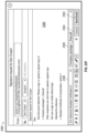
- FIG. 21 illustrates a table showing example completion criteria.
- FIGS. 22 A- 22 D illustrate example user interfaces, as may be presented to a user requested to sign a document.
- FIGS. 23 A- 23 H illustrate example user interfaces, as may be presented by a user creating a signature request for a document.
- FIGS. 24 A- 24 B illustrate representations of data describing a smart form.
- FIGS. 25 A- 25 B illustrate example user interfaces specifying user turns.
- FIGS. 26 A- 26 B illustrate example notification emails.
- User Input (also referred to as “Input”): Any interaction, data, indication, etc., received by the system from a user, a representative of a user, an entity associated with a user, and/or any other entity. Inputs may include any interactions that are intended to be received and/or stored by the system; to cause the system to access and/or store data items; to cause the system to analyze, integrate, and/or otherwise use data items; to cause the system to update to data that is displayed; to cause the system to update a way that data is displayed; and/or the like.
- Non-limiting examples of user inputs include keyboard inputs, mouse inputs, digital pen inputs, voice inputs, finger touch inputs (e.g., via touch sensitive display), gesture inputs (e.g., hand movements, finger movements, arm movements, movements of any other appendage, and/or body movements), and/or the like.
- user inputs to the system may include inputs via tools and/or other objects manipulated by the user. For example, the user may move an object, such as a tool, stylus, or wand, to provide inputs.
- user inputs may include motion, position, rotation, angle, alignment, orientation, configuration (e.g., fist, hand flat, one finger extended, etc.), and/or the like.
- user inputs may comprise a position, orientation, and/or motion of a hand or other appendage, a body, a 3 D mouse, and/or the like.
- Data Store Any computer readable storage medium and/or device (or collection of data storage mediums and/or devices). Examples of data stores include, but are not limited to, optical disks (e.g., CD-ROM, DVD-ROM, etc.), magnetic disks (e.g., hard disks, floppy disks, etc.), memory circuits (e.g., solid state drives, random-access memory (RAM), etc.), and/or the like.
- a data store is a hosted storage environment that includes a collection of physical data storage devices that may be remotely accessible and may be rapidly provisioned as needed (commonly referred to as “cloud” storage). Accordingly to certain implementations of the present disclosure, data stores may be encrypted, e.g., end-to-end-encrypted, to prevent unauthorized access or modification of data stored therein.
- Database Any data structure (and/or combinations of multiple data structures) for storing and/or organizing data, including, but not limited to, relational databases (e.g., Oracle databases, MySQL databases, etc.), non-relational databases (e.g., NoSQL databases, etc.), in-memory databases, spreadsheets, comma separated values (CSV) files, eXtendible markup language (XML) files, TeXT (TXT) files, flat files, spreadsheet files, and/or any other widely used or proprietary format for data storage.
- Databases are typically stored in one or more data stores. Accordingly, each database referred to herein (e.g., in the description herein and/or the figures of the present application) is to be understood as being stored in one or more data stores.
- Goal A step or intermediate state towards an outcome in a computer-assisted transaction.
- a transaction involving obtaining signatures from multiple individuals may comprise multiple goals, wherein obtaining each signature is one goal.
- One goal may comprise multiple sub-goals or tasks, which may be sub-forms, form sections or other action items.
- Term A portion (e.g., a provision) forming part of a document (e.g., a contract).
- a term may be represented as a textual portion of a document.
- Each term may be represented in different formats, for example different documents may have distinct wordings of a term.
- Some terms may have specific numerical or textual values associated with the terms.
- a term may relate to a number of days for a contracting party to perform an action, and a value for the term may specify the number of days.
- a term may relate to an identification of a person required to perform an action, and a value for the term may specify the person's identifying information.
- a term may relate a condition for a company to delay filing of a particular form, and a value for the term can include receipt of a certificate prepared by a CEO or a receipt of a certificate prepared by a President.
- a term can be utilized to refer to a particular portion of a document, and one or more values may be specified as forming part of the term.
- a system e.g., the goal optimization system 100 described below
- user roles can be created, with each user role being associated with particular permissions, security rights, access rights, and so on, and based on these associations, the system can enforce constraints on available actions that each user can perform.
- an electronic goal can include two entities performing a complex series of tasks to complete a contract, a venture financing round, stock transfer, and so on, and particular user roles (e.g., counsel, executive/partner roles, information technology roles, and so on) may have distinct actions that can be performed based on a state of the progression of the goal.
- a counsel for a first entity e.g., a venture capital firm
- may prepare an initial term sheet or contract e.g., as will be described herein, the system can analyze a provided contract/term sheet, and utilizing one or more ontology models and/or machine learning models, extract terms for presentation), while executives for the first entity may be required to negotiate and ultimately sign the term sheet/contract before the goal can progress.
- a second entity may review, negotiate, and ultimately sign, the term sheet/contract.
- an example step e.g., a step can represent one or more grouped tasks
- steps can be associated with executing a term sheet or contract, and upon the first and the second entities execution of the term sheet or contract, subsequent steps can be accessible, such as agreement with respect to core financing, closing of the transaction, and so on.
- the present disclosure may refer interchangeably to contracts, term sheets, and documents as illustrative examples when describing the functionality of the system. However, any types of suitable documents or groups of documents may be used in the system.
- a graph may describe relationships between nodes, such as edges connecting each node to itself or one or more other nodes, and can be stored as a graph data structure, stored in relational databases along with information describing the relationships (e.g., adjacency lists, matrices; incidence lists, matrices; and so on).
- each node of the graph can be associated with a particular task to be performed, and upon completion of the particular task, the system can traverse to a subsequent task via an edge.
- Each task can optionally be completed based on particular actions performed by one or more users, for instance a task to negotiate documents can include actions of (1) uploading a particular document and providing it to a negotiating user, (2) indicating approval, by all negotiating users, to the particular document, and optionally uploading other documents for discussion, messaging users, and so on.
- the graph can be associated with completing an electronic goal, and the nodes can be arranged such that one or more paths (e.g., a path can represent a traversal of edges along a same direction towards completion of the goal) can cause completion of the goal.
- Linkages between nodes in the graph may represent possible (e.g., logically valid) transitions between goals, or various tasks within a goal.
- this may allow the user to interact with the system sequentially, in a way that may be considered an implementation of a wizard, assistant or expert system.
- the system can monitor progression through the graph (e.g., completion of tasks), and can determine a present state associated with the progression.
- a state describes one or more of, a present task that is to be completed (e.g., by a user or user role), or optionally one or more tasks that are to be completed (e.g., by different users or user roles), an elapsed time since the goal was initiated, an estimated time remaining (e.g., as will be described, the system can monitor progression of multitudes of goals till completion, and determine estimates of remaining times along with other information, such as preferred paths through graphs, and so on), and other information indicative of a progress associated with completion of the electronic goal.
- the system can present useful information to users indicating (1) whether they have a particular task to complete, (2) a particular user role or user that is to complete a particular task, (3) a recommended path to traverse based on the state (e.g., the system can determine a particular task to subsequently complete based on a present), and so on.
- the system can present information identifying “a current task,” “a task owner” (e.g., as described below tasks can be assigned to particular users or user roles), and so on, ensuring that users are aware of any actions they need to take.
- User roles can be created and assigned to users of the system (e.g., users can create user accounts and indicate their role with respect to completion of the goal), for instance a first user role may be associated with an attorney, while a second user role may be associated with an executive; other example user roles are described in detail herein, and in general a user role can be any definable role.
- Each task may optionally be assigned to a particular user role, a particular user assigned the particular user role, and so on. In this way, each task may have one or more owners, and these owners can ultimately trigger the completion of the task.
- an example task can include executing a term sheet, document, or group of documents.
- a user role associated with an executive can be assigned the example task, such that only a user assigned as an executive can cause the completion of the task (e.g., the user can upload an executed term sheet or document).
- particular tasks can be delegated to other users of other user roles, while the system may disallow delegation of other tasks (e.g., with respect to the example of an executed term sheet or document, the system can disallow delegation to a user role that wouldn't normally bind a company, such as an outside counsel, employee, manager, information technology employee, and so on).
- users may be assigned the roles of primary and secondary owners of a goal, wherein the primary owners can either take an action related to the goal themselves, or delegate such action to a secondary owner.
- the secondary owners may then take actions that were delegated to them by a primary owner. Additionally, the secondary owners can affirmatively request the primary owners to have an action delegated to them.
- This allows the primary owners to efficiently delegate aspects of a goal as desired, while still remaining in control of the entire process.
- the system may comprise various default configurations comprising pre-assigned roles of primary and secondary owners for certain types of transaction, which may then be customized by the primary owners to reflect their preferences.
- the graph can indicate a particular user role that is to be assigned each task, for instance the system can store information describing assignments.
- the system can store information indicating tasks to be completed by attorneys, executives, members of a board, shareholders, and so on.
- the system can determine users that are to complete the new task.
- the system can present information to the determined users indicating the assignment (e.g., ownership of the task), and the system, or other users, can provide notifications to the determined users regarding completion of respective tasks.
- the system can present (e.g., in one or more user interfaces, such as in a web page being rendered on user devices of users) information identifying a current task that is to be completed along with one or more users assigned the current task.
- a present task to be completed e.g., a task, according to the graph, that causes progression towards the goal
- the system can present (e.g., in one or more user interfaces, such as in a web page being rendered on user devices of users) information identifying a current task that is to be completed along with one or more users assigned the current task.
- the system can determine a user or user role that is to be assigned each task upon traversing to the task, or traversing to within a threshold distance (e.g., according to one or more paths through nodes) of the task. For example, the system can monitor an average elapsed time that a particular user takes to complete actions or tasks, and can prefer assignment of the task to a user who more quickly completes actions or tasks. While the system may prefer a particular user who more quickly completes actions or tasks, the system can ensure that the particular user is assigned a user role that can complete the assigned task. For example, a particular user may complete tasks quickly, but be unable to generate contracts, execute contracts, and so on, and the system can select from among users assigned user roles that can complete the assigned task.
- a threshold distance e.g., according to one or more paths through nodes
- the system can further base the task assignment determination on a number of tasks presently assigned to users (e.g., the system can prefer a user that is not overly burdened with assigned tasks, such as a user with less than a mean number of assigned tasks, thus performing load balancing), a frequency with which the user checks information indicating a progression of the goal (e.g., the system can prefer assignment to a user that appears to be interested in progression), or the system can receive an identification of a particular user (e.g., a particular user role, such as a chief executive officer, can provide specific assignments of tasks to particular users).
- a number of tasks presently assigned to users e.g., the system can prefer a user that is not overly burdened with assigned tasks, such as a user with less than a mean number of assigned tasks, thus performing load balancing
- a frequency with which the user checks information indicating a progression of the goal e.g., the system can prefer assignment to a user that appears to be interested in progression
- the system
- the system can traverse through the graph towards completion of the goal according to completion of tasks assigned to users, and upon completion of a task, the system can assign subsequent tasks to users.
- the system can traverse to a subsequent task according to user actions implemented during completion of the task, or subsequent to completion.
- one or more tasks can be associated with executing a negotiated term sheet/contract between two entities.
- a user of the system can select the subsequent task to be completed. For instance, and as described below with respect to FIG.
- the user can interact with a user interface and indicate that one or more subsequent tasks are to be associated with performing a due diligence process.
- the user can interact with the user interface and indicate that one or more subsequent tasks are to be associated with executing core financing documents.
- users can have a level of autonomy with respect to traversing the graph and completing the goal. For instance, the users may prefer to execute the core financing documents first, while the due diligence process is temporarily put on hold, or while the due diligence process is ongoing.
- the system can ensure that tasks not appropriate for assignment at particular states cannot be inappropriately traversed to (e.g., the users may not be allowed to execute final contracts for the venture funding or other deal absent determination of core financing documents or other types of documents). Further description related to users selecting subsequent tasks is included below, with respect to FIG. 2 C .
- the system can constrain user actions available to be performed according to a state associated with completion of the goal. For example, while users are negotiating a document, users (1) that are not associated with the negotiation may be constrained in one or more actions until the document is negotiated (e.g., the users may not be able to provide revisions to the document, comment on the document, and so on), or (2) that are associated with the negotiation may be allowed to perform actions associated with completion of the negotiation (e.g., sign the document, generate revisions, and so on). As will be described below with respect to FIG.
- the system can enforce constraints on user actions based on limiting user interface interactivity with respect to user interfaces presented on user devices of particular users, or the system can receive user actions and reject the received user actions according to the constraints.
- the system can modify user interfaces, such as hiding, ‘greying’ out, or otherwise limiting interactivity with particular portions of user interfaces, such that constraints on user actions can be enforced.
- a user interface presented to a first user can be simplified according to enforced constraints (e.g., the system can modify or update a particular user interface, such as a template, according to the constraints), while a user interface presented to a second user may have expanded functionality (e.g., the second user may be assigned a current task, or be otherwise able to perform particular actions).
- the system can enforce a role-based security model with respect to user actions of users, thus ensuring that actions for completing complex goals remain sharply in focus to users.
- a particular user can determine that he/she is assigned a task (e.g., as described above, the system can present information identifying assignments of tasks), and similarly constraints on the user actions he/she can perform can be enforced, thus increasing a likelihood that the task is quickly completed (e.g., the particular user can determine that he/she is to obtain signatures on a document, and his/her user actions can be limited to contacting users, providing the document to them, uploading the executed document to the system, and so on).
- the system can constrain, or enable additional, user actions for the different task based on the completion of the task associated with the first user role.
- a task associated with the first user role can include negotiation of particular terms and/or clauses to include in one or more contracts.
- the negotiated terms and/or clauses can affect one or more different tasks associated with the second user rule. For instance, based on the selected terms and/or clauses, particular documents may need to be executed, drafted, and so on, by users assigned the second user role.
- the system can modify user interfaces to limit user actions associated with terms and/or clauses not selected (e.g., as illustrated in FIG. 11 B , a particular class of documents is indicated as not applying).
- each node can indicate tasks, actions, and so on, which are required to be completed for the system to traverse to the node. For instance, users assigned a first user role can complete a particular task, and the subsequent task may indicate that users assigned a second user role complete a different task before the subsequent task can be assigned to the first user role.
- the system can ensure that tasks are assigned when it is logically appropriate, and each node can be associated with information describing necessary tasks, actions, and so on (e.g., the system can store information with each node, such as logical condition information maintained with a graphical structure, or the system can store information with each edge connecting nodes, and the system can ensure that the logical conditions are satisfied prior to traversing the edge to a node).
- the system can store information with each node, such as logical condition information maintained with a graphical structure, or the system can store information with each edge connecting nodes, and the system can ensure that the logical conditions are satisfied prior to traversing the edge to a node).
- the system can monitor progress associated with completion of the goal.
- a user of the system can request that the system provide a current task to be completed and optionally a subsequent task to complete. That is, the system can determine an optimal path that will move progress towards the goal, for instance a path with the least action (e.g., least complexity, least number of tasks, a path determined to result in a least amount of time based on the system monitoring historical completions of similar goals, and so on).
- the optimal path can be based on progress information associated with the goal, optionally in combination with historical information. For example, the system can determine that tasks involving particular actions (e.g., negotiation of terms or specific terms; gathering of complex information, for instance while performing due diligence tasks; and so on) have taken longer than a threshold (e.g., longer than a median time with respect to completion of other tasks, longer than a median time for historical completions of the determined tasks, and so on), and can prefer a path that limits the extent to which tasks involving the particular actions are to be assigned.
- a threshold e.g., longer than a median time with respect to completion of other tasks, longer than a median time for historical completions of the determined tasks, and so on
- the system can utilize historical information (e.g., monitored progress information associated with other users that previously completed goals) to determine paths that resulted in a fastest completion time, least number of actions, and so on, and can compare the historical information with a presently occurring goal.
- the system can utilize machine learning models (e.g., trained using historical information associated with previously completed goals) to determine an optimal path through the graph, for instance based on features of the presently occurring goal (e.g., information describing the goal, types of user roles required, statistical information such as completion times for particular tasks, and so on).
- the system can ensure that goals are completed efficiently, and can further update and refine paths over time through monitoring multitudes of goals.
- the system can enforce privacy restrictions specified by users, or can anonymize data, or require that users ‘opt-in’ to use of their data.
- the system can perform complex analyses on documents, information, and so on, provided by users to democratize complex electronic goals through simplifying the documents, information.
- contracts can utilize complex terminology, be written in specific manners that non-attorneys may not understand or be able to modify.
- the system can analyze documents, contracts (e.g., contracts under negotiation), and utilizing generated and maintained ontologies, can parse specific terms from the analyzed documents, contracts, and present simplified summarizing information to users.
- the system can analyze a provided contract and determine values for specific terms.
- the system can generate user interfaces depicting values of particular terms (e.g., terms determined to be important for a particular user viewing the contract, any negotiated term, any term which based on historical information is determined to be contentious or important, and so on), and users can rapidly gain an understanding of the contracts.
- the system can generate contracts according to preferred formats, and users can merely provide values for particular terms, and receive fully generated contracts with the values included. In this way, negotiating contracts, maintaining electronic versions of contracts, and so on, can be simplified, with users merely reviewing values for particular terms, and not being required to peruse legally complex documents.
- FIG. 1 illustrates an example goal optimization system 100 in communication with user devices (e.g., user devices 110 A- 110 N).
- the goal optimization system 100 can enable users of user devices 110 A- 110 N to complete an electronic goal, for instance through constraining 104 user actions 112 of the users and traversing a graph 124 associated with the electronic goal.
- the goal optimization system 100 can be a system of one or more computers, or a system of one or more virtual machines executing on a system of one or more computers, and can be in communication with user devices 110 A- 110 N via one or more networks (e.g., the Internet).
- networks e.g., the Internet
- the user devices 110 A- 110 N can include laptops, mobile devices, wearable devices, tablets, computers, and so on, and can present user interfaces 102 to users of the user devices 110 A- 110 N. Additionally, the goal optimization system can access, store, maintain, and so on, one or more databases storing graph information 120 associated with one or more electronic goals.
- the goal optimization system 100 may be implemented via one or more computer system, including computer executable instructions (e.g., modules, engines, etc.), as described herein and below in reference to FIG. 19 .
- the term “system” and/or “goal optimization system” may refer to the goal optimization system 100 alone or in combination with one or more other aspects, devices, systems, and/or functionalities of the present disclosure.
- system and/or “goal optimization system” may include a subset of the aspects, devices, systems, and/or functionalities of the goal optimization system 100 , alone or in combination with one or more other aspects, devices, systems, and/or functionalities of the present disclosure.
- the goal optimization system 100 can store and maintain user account information associated with users of the user devices 110 A- 110 N, for instance the users can access the system 100 and create user accounts.
- users can be invited to participate in completion of an electronic goal, users can cause the initiation of an electronic goal.
- Each user can indicate a user role he/she is to be assigned during the electronic goal, or the user be assigned the user role from one or more other users, and the goal optimization system 100 can store the assignment.
- each user role can be assigned one or more tasks, and user assigned the user role can be constrained in user actions they can perform.
- the goal optimization system 100 maintains graph information 120 , for instance in one or more databases 120 or one or more storage subsystems, and can utilize the graph information 120 to traverse a graph associated with completion of an electronic goal.
- the graph information can be maintained as relational information stored in the graph information database 120 (e.g., relational databases), for instance one or more tables describing nodes along with tables indicating relationships between the nodes. Additionally, tables can be utilized to describe, or reference stored locations that indicate, conditions (e.g., logical conditions) that when satisfied, cause the goal optimization system 100 to traverse to a subsequent node via an edge.
- the system 100 can determine that conditions associated with a particular node are satisfied (e.g., completion of a task indicated by the particular node, such as a user uploading an executed document for storage by the system 100 ), and the system 100 can access one or more tables describing relationships between nodes, and identify a subsequent node.
- the particular node may have edges to two or more nodes
- the system 100 can determine a particular one of the two or more nodes to traverse to, for instance based on user actions performed during the particular node. Determining a particular node from two or more nodes to be traversed is described in more detail below, with respect to FIG. 3 .
- the system can be required to (1) access tables indicating nodes, and utilize the accessed tables to identify a present task to be performed, (2) monitor progress associated with the present task, and determine completion of the present task, (3 access tables indicating relationships between nodes, and identify one or more nodes connected via edges to a node associated with the present task, and optionally (4) determine which of the identified nodes is to be traversed.
- the goal optimization system 100 can optionally utilize a NoSQL database, such as a database that implements a graph data structure.
- the graph data structure may be represented in the database in various ways, including using adjacency lists (e.g., each node being assigned an identifier, such as an integer, and each edge being represented by a tuple of two node identifiers).
- the graph data structure can store, and directly access, nodes that represent tasks, with each node indicating one or more of, (1) actions associated with completion of the task, (2) actions that can be performed based on user role (e.g., a particular user role can be constrained in the actions users assigned the particular user can role can perform), and (3) an assignment of the node to a particular user or users assigned a particular user role.
- the graph data structure can store information indicating edges between nodes, with the edges optionally indicating one or more of: (1) a directionality between the nodes, or (2) logical conditions indicating relationships between the nodes. For instance, and as will be described below with respect to at least FIG.
- the goal optimization system 100 can identify a subsequent node according to edges from the particular node and optionally user actions with respect to the particular node or subsequent to completion of the particular node. As an example, subsequent to completion of the particular node, the system 100 can present a particular user with two or more options to proceed, and based on the particular user's selection, the system 100 can traverse to a node associated with the selection. In this way, the graph data structure can simplify representation and access of a graph associated with an electronic goal.
- the graph information database 120 can therefore maintain a graph as graph information 122 , such as a graph data structure, relational database information, adjacency, incidence, matrices or lists, and so on.
- graph information 122 such as a graph data structure, relational database information, adjacency, incidence, matrices or lists, and so on.
- a representation of an example graph 124 is included in FIG. 1 , and the example graph 124 includes an initial node 126 A associated with a particular task (e.g., ‘Task A’), connected via an edge 127 A to a subsequent node 126 B (e.g., node 126 B is associated with ‘Task B’).
- a particular user, or a particular user role can be assigned Task A, and the system 100 can monitor user actions of, for instance, the particular user.
- the system 100 can traverse from node 126 A to node 126 B, and the system 100 can assign another user, or user role, to Task B. In this way, the system 100 can determine a state associated with progress towards an electronic goal.
- node 126 E (e.g., associated with ‘Task E’), includes edges connecting node 126 E to subsequent nodes (e.g., associated with ‘Task G,’ and ‘Task F’).
- edges connecting node 126 E to subsequent nodes e.g., associated with ‘Task G,’ and ‘Task F’.
- the system 100 can determine which edge to traverse.
- edge 127 E connects node 126 E to itself (a graph with loops in it may be referred to as a pseudograph), and edge 126 E can indicate user actions that when performed, do not cause progression towards an electronic goal.
- a particular user may be assigned Task E, and the task may indicate that the particular user is to provide an executed document to the system 100 .
- the particular user can perform other user actions in addition to provide an executed document, for instance the particular user can provide a comment for viewing by other users (e.g., a comment with respect to the document), the particular user can provide a different document (e.g., a supporting document), and so on.
- These user actions optionally known as supportive actions, may result in a loop, and only upon completion of Task E will the system 100 traverse to a subsequent node.
- users of the user devices 110 A- 110 N can interact with the goal optimization system 100 via user actions 112 with respect to user interfaces 102 received from the goal optimization system 100 .
- the goal optimization system 100 can generate interactive documents (e.g., web pages) for presentation on the user devices (e.g., rendered by the user devices), with the interactive documents enabling the users to provide user actions 112 , view progress information associated with an electronic goal, generate notifications to be provided to other users, and so on.
- each user device can execute an electronic application (e.g., an ‘app’ downloaded from an electronic application store), and the executed electronic application can generate user interfaces 102 for presentation.
- the goal optimization system 100 can receive information from, and provide information to, the electronic applications, and the electronic applications can present information received from the system 100 .
- Example user interfaces 102 are described herein, with respect to FIGS. 2 B, 7 B- 7 D, 8 , 9 A- 9 G, 10 , 11 A- 11 B, 12 A- 12 D, 13 , 14 A- 14 D, 14 F- 14 O , 14 Q 1 - 14 Q 2 , 14 R, 15 , 16 D, 16 F- 16 G, 17 A- 17 O, 22 A- 22 D, 23 A- 23 H, 25 A- 25 B, and 26 A- 26 B, including user actions with respect to the user interfaces 102 .
- users can upload documents for storage by the system 100 , access documents uploaded by other users, engage in discussions with other users, electronically sign documents (e.g., as illustrated in FIGS. 14 C, 14 E- 14 O, 22 A- 22 D, and 23 A- 23 H ).
- the system 100 can enforce constrains on user actions.
- the system 100 can modify user interfaces 102 to limit available functionality that can be performed (e.g., the system can limit particular users from uploading or viewing documents, while enabling other users to upload, discuss, and otherwise negotiate documents).
- FIG. 2 A further illustrates an example implementation of goal optimization system 100 (also referred to herein as “the system”).
- the goal optimization system 100 can be in communication with one or more user devices (e.g., user device 110 ), and a user of a user device 110 can view, interact, with user interfaces 116 presented on the user device (e.g., via a display of the user device, such as a touch screen display).
- the goal optimization system 100 is in communication with, and optionally maintains, a user information 128 database that stores information associated with users of the system 100 .
- Users can utilize user interfaces 116 to create user accounts with the system 100 , such as creating a user name/password, and optionally user profile information such as a name, address, phone number, and so on.
- users can indicate respective user roles, such as whether they are attorneys, executives, employees, or an arbitrary role, with respect to particular electronic goals.
- the system 100 can store information identifying available user roles for selection according to a particular electronic goal for which users are trying to complete, and the system 100 can enable selection of one of the available user roles.
- the system 100 can require verification of a user role, such as requiring one or more already registered users to indicate acceptance of a new user and user role, requiring documentation be provided verifying a new user's role, and so on.
- users of the system 100 can cause the system 100 to cause one or more notifications 102 to be provided to potential users, requesting that the potential users create user accounts with the system 100 to fulfill particular user roles.
- the system 100 can present information indicating all present users and associated roles, along with user roles that do not have assigned users, and a user of the system 100 can request that the system 100 generate notifications to a particular email address, phone number, application executing on a particular user device, and so on, requesting that a potential user fulfill an unassigned user role.
- the goal optimization system 100 is further in communication with, or optionally maintains, a data storage database 129 that can store documents, images, video, or any arbitrary information that is received from, or is made accessible to, users of the user devices (e.g., user device 110 ).
- a data storage database 129 can store documents, images, video, or any arbitrary information that is received from, or is made accessible to, users of the user devices (e.g., user device 110 ).
- the system 100 can store revisions of documents, such as contracts, and users of the system 100 can access the documents, electronically execute the documents, and so on.
- Data for example the data included in databases 120 - 129
- Data can be encrypted and/or permissions can be associated with portions of the data.
- all access to data included in databases 120 - 129 can be mediated through a database layer wherein software layers (e.g., user interfaces) invoke the database layer (e.g., through an API) for all database accesses.
- Data permissioning can be enforced through channels implemented on the database layer.
- Data related to each transaction e.g., related to individual goals
- each partition e.g., each document
- Each channel or access permission may associate one or more partitions with one or more users authorized to access the respective partitions.
- a user may be granted access to a set of channels based on their user roles in the transaction (e.g., goal).
- Each user can be granted access to a partition if the access permissions associated with the user comprise at least one access permissions granting access to the partition contain at least one channel associated with that partition.
- the enforcement of access permission can be implemented at the database layer by matching the list of document channels and user granted channels; advantageously, this may allow conforming layers on top of the database layer to the permissions model implemented by a database layer.
- the goal optimization system 100 can enable an initial selection of an electronic goal (e.g., a user interface 116 presented to a user can present one or more electronic goals, and the user can select an electronic goal optionally along with information such as, names of entities involved in the electronic goal, and so on). Based on the initial selection of the electronic goal, the system 100 can access graph information 120 associated with the electronic goal. As described above, graph information 120 can indicate tasks that are to be completed for completion of the electronic goal, and can indicate particular user roles that are to be assigned each task. Based on the selection of the electronic goal, the system 100 can indicate user roles that are required for completion of the electronic goal (e.g., an executive level officer of a company may be required for a venture funding round to be completed).
- an executive level officer of a company may be required for a venture funding round to be completed.
- the goal optimization system 100 includes a user role action engine 108 that can (1) cause assignment of users to particular user roles (e.g., a user role with respect to a particular entity involved in the electronic goal, for instance a venture capital funding firm or a company interested in receiving venture funding, and so on), (2) determine constraints on user actions for enforcement based on a present task, and (3) determine assignments of tasks to particular users or particular user roles.
- users of the system 100 can create user accounts (e.g., provide a user name, password), and indicate their user role with respect to the selected electronic goal.
- the user role action engine 108 can maintain assignment information (e.g., in the user information database 128 ), and can further cause notifications 102 to be provided to potential users requesting that the potential users create user accounts for the selected electronic goal.
- the user role action engine 108 can monitor a present task assigned to a particular user or user role, and can enforce constraints on user actions that can be performed. For instance, a present task may include negotiating a term sheet or contract, and the user role action engine 108 can constrain user actions with respect to executing a final version prior to particular users indicating consent to the negotiated term sheet or contract.
- the goal optimization system 100 can generate notifications 102 to be provided to users of the system 100 , for example notifications can be automatically generated by the system 100 periodically (e.g., after a threshold amount of time), in response to completion of tasks or particular actions that were performed, and optionally users can subscribe to notifications being received from the system 100 based on specified conditions.
- notifications can provide summary information describing progression of the selected goal, and can include particular tasks that have been completed (e.g., within a threshold period of time), particular tasks that are to be completed, tasks that are to be completed by a particular user or particular user role, and so on.
- specified conditions can include updates of particular users, particular user roles, updates associated with a particular entity (e.g., with respect to a venture financing goal, a user can subscribe to updates from an investing company and/or a company receiving venture financing).
- a user e.g., an executive
- the system 100 can generate and provide notifications (e.g., in substantially real-time, or the system can obtain a threshold number of updates, or wait a threshold amount of time, to provide notifications).
- the goal optimization system 100 can maintain subscription information, for instance in one or more databases (e.g., the user information database 128 ), and can associate the subscription information with particular user accounts. Additionally, the system 100 can store, or receive information indicating (e.g., from a particular user or user role), subscription information for all users, a portion of users (e.g., users associated with a same entity as the particular user), a portion of user roles, such that a base-line can established, ensuring that all or particular users associated with a same entity receive update information.
- information indicating e.g., from a particular user or user role
- subscription information for all users e.g., from a particular user or user role
- a portion of users e.g., users associated with a same entity as the particular user
- a portion of user roles such that a base-line can established, ensuring that all or particular users associated with a same entity receive update information.
- Notifications 102 can include emails generated by the goal optimization system 100 which are provided to email addresses associated with users, with the emails optionally graphically depicting updates.
- emails generated in response to a particular document being uploaded to the system can specify the action (e.g., document uploaded) along with information describing the document, and can graphically depict a state associated with progression of an electronic goal (e.g., a particular task, a particular step, and so on).
- the email can include selectable elements that can be associated with references (e.g., links) to the goal optimization system 100 .
- a selectable option can be associated with causing a user device presenting the email to navigate to a particular content item (e.g., web page) that presents information related to the notification, or enables user actions related to the notification (e.g., signing a document, uploading and document, making one or more comments visible to other users, and so on).
- a particular content item e.g., web page
- user actions related to the notification e.g., signing a document, uploading and document, making one or more comments visible to other users, and so on.
- the system may generate emails based on substituting information into a template, which may be similar in many aspects as discussed herein with reference to contract templates.
- the user may also be able to respond directly to the notification (e.g., clicking on a link inside an electronic message, responding to an email message, etc.), thus triggering a corresponding action in the system.
- a response e.g., a response email from a user, or a request from a user's web browser following a link in an email
- each email may comprise an identification token, such as a user identifier, which may then be used by the system to find the user associated with the response.
- a user may be able to perform a variety of actions or tasks by responding to an email from the system, such as sending requests to other users to perform a task, granting permissions to other users to perform a task, sending reminders or follow-ups to other users related to a task, inviting new people to a transactions (e.g., allowing new user accounts to be created), completing a task (e.g., uploading a document or confirming that a certain action, such as a review, has been performed).
- a transaction e.g., allowing new user accounts to be created
- completing a task e.g., uploading a document or confirming that a certain action, such as a review, has been performed.
- An example notification 202 (e.g., email) is illustrated in FIG. 2 B , with the notification 202 providing summary information associated with actions, completions of tasks, and so on.
- completion of a particular task is indicated 204 (e.g., the notification 202 indicates that a particular user role, investor counsel, is ready to sign term sheet documents) along with the particular task's location within a step (e.g., as will be described below, with respect to FIGS. 8 and 9 A- 9 H , executing an initial term sheet can be a step that includes multiple tasks, such as negotiating the term sheet or contract, signing the term sheet or contract, and so on).
- the goal optimization system 100 can access graph information associated with an electronic goal, and utilizing the graph information the system can determine tasks associated with particular tasks.
- an initial task e.g., negotiating a term sheet
- the email graphically depicts the completion, which in the example includes a solid circle next to a textual descriptor of the initial task
- a next task is to begin (e.g., signing the negotiated term sheets).
- this next task e.g., signing the term sheets
- counsels e.g., ‘Investor Counsel,’ representing a counsel for an entity that is investing money into a company.
- the notification 202 further includes a selectable option 208 , which upon selection or interaction, can cause a user device presenting the notification 202 to navigate to a content item (e.g., web page) presenting ‘more details’ as illustrated.
- notifications 102 can encompass one or more other types of electronic information being provided to users.
- a notification 102 can include a message (e.g., an SMS, MMS, message) being provided to a user, or a notification 102 can include activation of an application executing on particular user devices and presenting, via the application, information.
- the user device 110 can include an application engine 114 , with the application engine 114 optionally being an electronic application (e.g., the electronic application can be downloaded from an application store) in communication with the system 100 .
- the application engine 114 can periodically poll the system 100 for updates (e.g., notifications 102 ), or the system 100 can provide notifications 102 to the application engine 114 (e.g., as a push).
- the goal optimization system 100 can interact with users of user devices (e.g., user device 110 ) via user interfaces 116 presented to the users.
- the goal optimization system 100 can further interact with users through emails, with the emails specifying identifiers associated with particular tasks, and with the emails enabling users to provide information to the system 100 which may cause the system 100 to (1) update user interfaces 116 , for instance update user interfaces for particular users to specify information received in an email, (2) update particular tasks, (3) cause completion of particular tasks, and so on.
- the system 100 may assign a particular task to a user, for instance uploading a particular document, and the user can access user interfaces 116 to upload the particular document.
- the user may utilize his/her email program, app, web interface, and so on, and draft an email that specifies a particular email address associated with the goal optimization system 100 , and which includes the particular document attached.
- the system 100 can receive the email, identify the user, and based on the assignment of the user to a task associated with uploading a document, may determine that the task has been completed.
- the email may include a reference to the task, such as a unique identifier (e.g., a string of characters, numbers, that uniquely identify the task), a textual description of the task (e.g., ‘attached is the [name] document—please execute’) and the system 100 can parse the textual description to identify the task.
- a unique identifier e.g., a string of characters, numbers, that uniquely identify the task
- a textual description of the task e.g., ‘attached is the [name] document—please execute’
- system 100 may also provide a platform for communication amongst users or groups of users, such as a messaging system or chat.
- tasks, goals, documents, etc. may be mentioned or embedded in messages sent by a user, and can thus be immediately accessed by a recipient or recipients of the message.
- a user mentions an action or goal in a message e.g., “sign form 14”, review document X”
- the system may create links or references to those actions, goals, documents, etc. so that they can be quickly accessed or performed.
- a user may be also able to use the communication platform to contact support; this may include either a human representative, or a chatbot, artificial intelligence, or expert system that interacts with the user in a way similar to human interaction.
- the system 100 can update user interfaces 116 presented to the particular user and/or other users.
- the particular user can attach a document to the email, thus completing the user's assigned task, and the system 100 can update user interfaces presented to other users indicating a subsequent task to be performed (e.g., signing the document).
- interactions with the system 100 are not constrained solely via interactions with user interfaces 116 , and can be expanded.
- users can text (e.g., through SMS, MMS) a particular number associated with the system 100 , and the system 100 can similarly parse the text, obtain attachments to the text (e.g., an MMS message may contain an attachment, or the text can include a link to a cloud storage location and download an attachment, and so on).
- the goal optimizations system 100 can enable persons who have not created user accounts with the system 100 to be assigned user roles, and perform user actions 112 .
- a particular action, or task may be required to be performed by a different user (e.g., as described above, constraints on user actions can be enforced by the system 100 , such that to perform an action or complete a task, a particular or particular user role can be required), and the user can request that the system 100 generate a notification 102 to be provided to a person who can act as the different user.
- the system 100 can indicate to the user that a particular user role (e.g., counsel) is required to perform an action, or to complete a task, and the user can interact with the system 100 to specify one or more of (1) a name of a person who can function as the particular user role (e.g., an attorney), (2) contact information (e.g., email address, and so on.
- the system 100 can generate a notification 102 , and provide the notification 102 to the person.
- the person can receive the notification 102 , and optionally create a user account (e.g., as described above), or optionally perform actions in response to the received notification 102 (e.g., as described above, the person may respond to an email with instructions the system 100 can parse, including attaching a document).
- the system 100 can provide a notification 102 to the person (e.g., an email describing that the person is to provide a document, and further describing an electronic goal, identifications of the entities, and so on), and the person can respond to the notification with an attached document.
- the person may not be required to create a user account, and can instead perform a limited function which can reduce a burden on people interacting with the system.
- the email can include a selectable object, which upon interaction, can cause a user device utilized by the person to navigate a secure content item (e.g., web page) associated with the system 100 .
- the person can then utilize the secure content item to perform actions, for instance upload a document.
- the system 100 can create secure sessions, for instance secure web based tokens which can optionally expire after the person performs specified actions, after a threshold amount of time, or any user definable conditions.
- each task or user action associated with a graph can correspond with a type of event.
- Each type of event can be associated with a set of email templates, and each email template can be designed for one or more user roles associated with the graph.
- the system can query the email template associated with the user action. Based on the user role associated with each email template, the system can query a list of users being in that role. Those users are the receivers of the emails. The system can then compose email content for each of the users by querying the state of the transaction and the user's information (e.g., the state associated with a graph is described above). The queried data can be applied to the template to compose a specific email content. Once the email content is ready, the system can provide a request to an email server to send out that email.
- each email sent out by the system can indicate an identification token that allows the system to determine the context of the email.
- the token can be sent back together with the reply content.
- the system can identify the token to determine the context of the email (e.g., the intended discussion channels, the corresponding action in the workflow, particular task or step, and so on).
- certain actions can be automatically performed by the system, e.g., import the email content to a discussion channel, or upload an attachment to a document sharing channel. In this way, users can interact with the system via emails.
- the goal optimization system 100 can optionally analyze and/or parse documents received from users, and can present summary information describing the documents. For instance, and as will be described in more detail below with FIGS. 16 A-G , 17 A- 17 O, and 18 , the system 100 can utilize ontologies to indicate particular terms (e.g., negotiated terms) and associated values of the particular terms.
- the system 100 can present information summarizing large complex documents (e.g., contracts), such that important features of the documents can be quickly presented in user interfaces 116 to users.
- the system 100 can analyze multitudes of contracts, and based on machine learning techniques (e.g., the system 100 can process a training set of contracts and terms identified in the set of contracts, and can generate rules associated with identifying portions of contracts that include terms) can parse received contracts and rapidly obtain terms.
- the system 100 can store ontology information indicating synonyms for terms, textual language that is associated with each term (e.g., a relevant portion of a contract that identifies a particular term may be a full paragraph long, a portion of a paragraph, and so on), and so on.
- the system 100 can identify terms in a contract (e.g., negotiated terms, for instance as described below with respect to FIGS. 8 and 9 A- 9 H ), and present summary information to the user indicating values of the terms, and/or present portions of the contract that include the identified terms.
- FIG. 2 C illustrates example tasks (e.g., Task A 210 and Task B 212 ) identified in an example graph (e.g., directed graph) associated with an electronic goal.
- the goal optimization system 100 can monitor progression through a graph associated with an electronic goal, with an example graph described above and illustrated in FIG. 1 .
- the graph can include nodes associated with tasks, with the nodes connected via edges to one or more other nodes.
- Each node can assigned to a particular user, or particular user role, and the assigned user, or any user of the assigned user role, can cause completion of an associated task.
- a task can be associated obtaining a fully executed version of a document (e.g., contract), and a particular user role (e.g., attorney) can be assigned the task.
- the attorney can cause completion of the task upon providing a fully executed document (e.g., the document can include signatures from executives, board members, and so on) for storage in the system 100 .
- the system 100 can assign a task, for instance Task A 210 , to a particular user role (e.g., User Role A) based on information associated with an electronic graph that includes Task A 210 . That is, the system 100 can access information indicating assignments of user roles to specific tasks includes an electronic graph, and upon completion of a prior task, the system 100 can assign a subsequent task (e.g., Task A 210 ) to a particular user role.
- the assignment information can be generated, or specified, by users of the system 100 , for instance using the system 100 the users can create an electronic goal, specify nodes to include in an associated electronic graph (e.g., the users can indicate particular tasks to be completed), and further specify assignments of tasks to particular user roles.
- the system 100 can optionally present user interfaces that include functionality for creating tasks (e.g., a user of the system 100 can manipulate user interface elements, such as ovals, circles, and so on, and connect them together to form an electronic graph), defining actions that cause completion of the created tasks (e.g., the user can indicate particular conditions that must be satisfied before a task is to be completed, such as uploading documents, confirming terms, sharing documents with other users or user roles, and so on), optionally defining constraints on user actions of user roles not assigned each created task (e.g., the user can indicate that for a task assigned to counsel, other users may not be able to upload documents, created revisions of documents, and so on).
- the system 100 can access information indicating assignments of each traversed node (e.g., assignment of associated tasks) to a particular user role.
- Task A 210 is assigned User Role A (e.g., User Role A is specified as an owner of Task A). That is, User Role A (e.g., any user assigned User Role A) can cause completion of Task A 210 based upon performance of particular user actions. As will be described below, with reference to at least FIG.
- a user assigned User Role A can request that the system 100 present information identifying one or more of, (1) a description of Task A 210 , (2) a task owner (e.g., the system 100 can indicate that the user is the owner), (3) user actions that can cause completion of Task A, (4) a location of Task A 210 with respect to an electronic graph (e.g., a step in which Task A 210 is located, a graphical depiction of the electronic graph, such as a depiction hat can be zoomed into and from which the user can view detailed information describing each task), optionally other information including an amount of time the user has spent on the task.
- a user assigned User Role A can easily ascertain that they have been assigned Task A, and what particular user actions are required of them to cause completion of Task A.
- the system 100 can identify an edge connecting Task A 210 (e.g., a node associated with Task A) and Task B 212 (e.g., a node associated with Task B).
- Task A 210 e.g., a node associated with Task A
- Task B 212 e.g., a node associated with Task B
- there may be more than one edge such that a task different from Task B 212 may also be a potential next task to be completed.
- the system 100 can determine which edge to follow based on particular user actions performed during Task A 210 . For example, to complete Task A 210 , a user assigned User Role A may have to ultimately upload a particular document, however prior to uploading the particular document, the user may have one or more optional user actions.
- the user may select a format associated with the particular document, may include particular terms in the particular document, may perform a user action that requires an intermediary task to be performed prior to Task B 212 being assigned (e.g., a particular user role may have to approve inclusion of certain terms, and so on).
- the system 100 can traverse from Task A 210 via a particular edge based on the user actions performed.
- information associated with each edge e.g., maintained in a graph database structure as described above
- Task B 212 is assigned to a user of User Role B, and upon the assignment, optionally the user can receive a notification indicating the assignment, view user interfaces generated, at least in part, by the system 100 that indicate the assignment along with a description of Task B 212 , any required user actions associated with its completion, and so on.
- the assignment of Task B 212 to User Role B can be determined, as described above, based on maintained information associated with the electronic graph.
- Task B 212 may be based, at least in part, on user actions that were previously performed.
- Task A 210 may have been a task associated with determining terms associated with contract.
- a different user role may be assigned Task B 212 .
- the terms may generally be associated with intellectual property concerns, and the system 100 can determine that Task B 212 is to be assigned to an intellectual property counsel role.
- the terms may generally be associated with corporate issues, and the system 100 can determine that Task B 212 is to be assigned to a corporate counsel role.
- the system 100 can analyze, or obtain information indicating, the determined terms, and assign Task B 212 to a user role that is most (e.g., commonly) associated with the terms.
- certain tasks may be assignable to more than one user role, and the system 100 can cause the assignment of Task B 212 to a single user role (e.g., the system 100 can select the user role from a multitude of user roles) or assignment of Task B 212 to two or more user roles (e.g., users of either user role can cause completion of the Task B 212 ).
- certain tasks such as obtaining signatures from a multitude of other users, can be assignable to multiple user roles (e.g., counsel, secretary, and so on).
- the system 100 can access information indicating the multiple assignment, and can select either a counsel (e.g., attorney) or secretary to be assigned Task B 212 , or can allow users of either user role to be assigned.
- the system 100 can obtain information indicating response times, completion times, and other information relevant to a rapidity with which users of a particular user role complete tasks.
- the system 100 can prefer assignment of Task B 212 to a user role that completes tasks faster.
- the system 100 can access information indicating a frequency with which users of each user role confer with other users, how close in proximity they are, and so on, such that users of a particular user role might be more apt to perform the task (e.g., obtain signatures from other users).
- the system 100 can, in general, monitor statistical information associated with electronic goals, such as timeliness of particular users (e.g., how quickly each user completes tasks, completes actions assigned to them, and so on). Utilizing the statistical information, the system 100 can indicate users that are moving electronic goals forward, and if there is an option to select multiple users to be assigned a task, the system can prefer 100 assignment of a timely user. For example, as illustrated in FIG. 2 C , Task B 212 has been assigned to User Role B. The system 100 can access information identifying users assigned User Role B (e.g., as described above, with respect to FIG.
- users can be assigned a user role upon creation of their user accounts) and can select a particular user assigned User Role B based on the statistical information. That is, the system can designate a particular user (e.g., ‘Jane Doe’) be assigned completion of Task B 212 , and only the particular user can complete Task B (e.g., other users assigned User Role B may be able to perform user actions for which other user roles are constrained, however only Jane Doe may be able to cause completion of Task B 212 ).
- a particular user e.g., ‘Jane Doe’
- Task B e.g., other users assigned User Role B may be able to perform user actions for which other user roles are constrained, however only Jane Doe may be able to cause completion of Task B 212 .
- FIG. 2 D illustrates tasks separated into example steps (e.g., Step A-Step D 220 - 250 ), which can result in completion 224 of an electronic goal.
- a graph e.g., a directed graph
- the graph can include nodes (e.g., associated with tasks) that are grouped into particular steps. That is, a step can represent a group of nodes, such that discrete steps associated with the electronic goal can be maintained.
- the system 100 can present information indicating a particular step users are on.
- the system 100 can present a description of a step for better ease of understanding, and optionally a graphical depiction of the electronic graph for example as illustrated in FIG. 2 D (e.g., tasks grouped in steps, optionally a present step can be highlighted or otherwise identified).
- Step A 220 of the graph can be an initial step, and the initial step can include a multitude of tasks 222 .
- Step A either Step B 230 or Step C 240 can be traversed to, and as will be described below with respect to FIG. 9 G , a particular user can indicate which step is to be next completed. That is, upon completion of a final node grouped into Step A 220 , the system can 100 can identify two edges connecting the final node to initial nodes of Step B 230 and Step C 240 . The system 100 can then traverse one of the edges based on, as described above, a user selection of a next step.
- the system 100 can enable a subset of users to be assigned tasks within Step B 230 , and a different subset to be assigned tasks within Step C 240 . That is, if the tasks in Step B 230 are independent from the tasks in Step C 240 , then the system 100 can optionally allow the tasks to be performed at a same time. The system can optionally ensure that a same user isn't assigned a task from both Step B 230 and Step C 240 (e.g., such that the same user can focus on one step), or optionally the system 100 can allow assignments from each step (e.g., a particular user, such as a supervisory user, can specify whether this is to be allowed).
- a particular user such as a supervisory user
- Step B 230 the system 100 can optionally constrain user actions associated with Step C 240 . That is, the system 100 can grey out user interface elements (e.g., as will be described below with respect to FIG. 3 B ) associated with Step C 240 .
- Step B 230 can be associated with performing a due diligence process (e.g., as described below, with respect to FIGS. 10 and 11 A- 11 B ), and Step C 240 can be associated with performing a core financing process (e.g., as described below, with respect to FIGS. 12 A- 12 D ), and upon selection of Step B 230 , the system can limit user actions associated with core financing, such as access to user interfaces describing the core financing processing, reviewing core financing documents, and so on.
- due diligence process e.g., as described below, with respect to FIGS. 10 and 11 A- 11 B
- Step C 240 can be associated with performing a core financing process (e.g., as described below, with respect to FIGS. 12 A- 12 D )
- Step D 250 requires completion of both Step B 230 and Step C 240 , for instance an edge associated with an initial task grouped in Step D 250 can specify conditions, and the conditions can indicate that both (1) Step B 230 , and (2) Step C 240 , has been completed. In this way, steps can be logically separated, and accessed based on conditions, ensuring that users begin particular steps at appropriate times.
- the system may advantageously represent and enforce workflows and dependencies.
- a typical process cycle of a task involving a legal document may include iterative creation by legal drafters, a review process by executives, the distribution to various parties for signing, and the collection of signatures. It may be undesirable to skip steps during this process; for example, it might be desirable to prevent non-reviewed documents from being distributed for signing.
- an electronic graph e.g., as described herein in reference to various figures
- the various permissible transitions may be represented as links, and the non-permissible as an absence of links.
- the system may be able to easily represent complex workflows involving multiple tasks, parties, and participants.
- Various tasks may be aggregated or combined, for example by providing means for batch signing, batch sharing or batch downloading related to tasks.
- certain aspects may be associated with their own flows or graphs.
- such flows or graphs may enable an efficient negotiation that moves the aspect from drafting internally and sharing, to counterparties in iterative cycles.
- an iteration finalizes (e.g., through ready-to-sign, sign, and exchange states)
- the flow can be reversed, providing optimal flexibility around negotiation.
- the system also includes flows or graphs including batch processing of documents for download/upload/sharing/etc.
- these flows or graphs may be further integrated with editing/redlining and parsing of legal terms (e.g., as described herein).
- FIG. 2 E illustrates various graphs or graph-like relationships (which may comprise data structures or databases), and various structures that may be used to represent them.
- Graph 262 is an example of an undirected graph, wherein the numbered fields 0-9 comprise nodes and the lines connecting the nodes represent relationships.
- Clusters 268 shows example clusters, which may be considered as a set of graphs which may be disjoint.
- Data structure 266 represents an adjacency list which may be used to represent a graph or cluster, such as graph 262 or cluster 268 .
- adjacency lists such as data structure 266
- the graphs are lightly-connected graphs or clusters (e.g., graphs or clusters wherein the number of nodes is high compared to the number of linkages per node).
- Adjacency lists 266 may also allow for efficient adding and removal of nodes, e.g., as an operation in constant time, as entries related to nodes that are not connected to the added or removed nodes may not need to be accessed.
- Data structure 264 is an adjacency matrix, which may also be used to represent a graph or cluster, such as graph 262 or cluster 268 .
- adjacency matrices such as data structure 264 may allow for more efficient storage and processing of highly-connected graphs or clusters, e.g., where the number of connections per node is comparable to the number of nodes.
- Adjacency matrices such as data structure 264 may also allow for more efficient access and processing, particularly vectorized access and processing (e.g., using specialized hardware or processor instructions for matrix math), to the graph or cluster data because each matrix row corresponding to a node may have the same size irrespective of the number of linkages by node.
- various data items may be stored, processed, analyzed, etc. via graph-related data structures, which may provide various storage and processing efficiency advantages described. For example, as shown in FIG.
- advantages of graph-related data structures may include: built to handle high volume, highly connected data; efficient in computing relationship queries than traditional databases, either using adjacency matrices, or adjacency lists; can easily add to the existing structure without endangering current functionality; structure and schema of a graph model can easily flex; new data types and its relationship; evolves in step with the rest of the application and any changing business data requirements; can easily add weights to edges; can use Optimal amount of computer memory, etc.
- FIG. 3 A is a flowchart of an example process 300 of traversing an electronic graph associated with a goal.
- the process 300 will be described as being performed by a system of one or more computers (e.g., the goal optimization system 100 ).
- the system identifies a task to be completed by a particular user role (block 302 ).
- the system can access a graph associated with completion of an electronic goal. Users involved in the electronic goal and create user accounts with the system, or optionally as described above can perform actions, complete tasks (e.g., as described above, a task can require performance of one or more actions), and so on, without creating user accounts, and the users can be assigned tasks for completion.
- complete tasks e.g., as described above, a task can require performance of one or more actions
- the users can be assigned tasks for completion.
- daylight into complex electronic goals can be established, and users can always be aware of who is assigned a present task and what actions the present task entails (e.g., an example user interface illustrating this daylight is described below, with reference to FIG. 12 B .) Therefore, the system can identify a present task and a particular user role that is assigned completion of the task.
- the system presents information to users associated with the particular user role (block 304 ).
- a present task e.g., as described above, the system can access a graph, and based on traversing edges, can arrive at the present task
- the system can present information to users assigned the particular user role the assignment of the identified task.
- the system accesses graph information 306 , and in response to completion of the present task, identifies one or more subsequent tasks based on the graph information (block 308 ).
- the system determines completion of the present task based on actions associated with the present task being performed. As described above, the system traverses the graph and identifies subsequent tasks connected via edges to the present task.
- the system can determine a particular subsequent task to be assigned based on, for example, user actions performed during the present task. That is, the system can access the graph information (e.g., database 306 ), and determines whether conditions associated with edges to the subsequent task are satisfied (e.g., a first edge may indicate a condition associated with uploading a particular document, while a second edge may indication a condition associated with uploading a different document).
- FIG. 3 B is a flowchart of an example process 310 for constraining user actions according to user role.
- the process 310 will be described as being performed by a system of one or more computers (e.g., the goal optimization system 100 ).
- users of the system can interact with the system via user interfaces presented on user devices (e.g., laptops, computers, tablets, mobile devices, wearable devices), with the user devices enabling the users to perform user actions, such as communicating with other users, uploading documents, reviewing documents or other information, generating revisions of documents or other information, electronically executing documents (e.g., described below, with respect to FIGS. 14 C, 14 J- 14 P, 20 , 21 , 22 A- 22 D , and 23 A- 23 H).
- user devices e.g., laptops, computers, tablets, mobile devices, wearable devices
- user actions such as communicating with other users, uploading documents, reviewing documents or other information, generating revisions of documents or other information, electronically executing documents (e.g., described below, with respect to FIGS. 14 C, 14 J- 14 P, 20 , 21 , 22 A- 22 D , and 23 A- 23 H).
- the system can enforce constraints on user actions that can be performed based on a state associated with progression of the goal, with the state indicating at least a present task that is assigned and optionally a particular user role associated with the present task.
- a role-based security model in which permissions (e.g., access rights to files, network devices, and so on) can be defined on a role basis, and users assigned particular users, the system can enforce constraints on user actions available for to users based on (1) a present state, and (2) a type of user role of each user. In this way, users can be guided towards completion of a present task, for instance the system can constrain user assigned user roles not relevant to the present task while limiting user actions of users assigned to the present task to user actions relevant to completing the present task.
- the system can limit an extent to which user roles not relevant to a present task can interfere with progression of the goal. For example, if a present task is associated with determining and uploading (e.g., for negotiation) a term sheet, the system can allow counsel (e.g., attorneys) to upload term sheets (e.g., revisions of term sheets), while constraining other user roles to upload term sheets. In this way, the other user roles can review and approve (e.g., sign) the uploaded term sheet, and/or can provide feedback to counsel regarding specifics of the term sheets which the counsel can implement (e.g., upload a new revision of the term sheet).
- counsel e.g., attorneys
- the system determines a state associated with progression of electronic goal (block 302 ). As described above, the system can access graph information, and identify a present task assigned for completion. The determined state can indicate the present task, a particular user or user role assigned the present task, and so on.
- the system determines constraints on user actions capable of being performed by users of disparate user roles (block 314 ).
- the system can store information indicating user actions that can be performed by (1) users of a user role assigned the present task, and (2) users of user roles not assigned the present task.
- the graph information e.g., as described above, with respect to FIGS. 1 and 2 A- 2 E
- constraints on user actions e.g., a subset of a total amount of user actions
- specific user actions that are capable of being performed by each user role. Since certain user roles, while not assigned a present task, may have relevance to completion of the present task, these certain user roles can be allowed to perform specific user actions.
- a present task can be the preparation and uploading of documents, and can be assigned to counsel (e.g., in-house attorneys), with the documents requiring signatures of executives or board members. Therefore, the executives or board members may be capable of viewing the uploaded documents, commenting on the uploaded documents, optionally redlining the uploaded documents, but not be allowed to themselves upload a new version of the documents. Additionally, for a task associated with obtaining signatures of executives or board members, the task may similarly be assigned to counsel, while the executives or board members may be constrained to (1) review the documents, (2) electronically execute the documents, and/or (3) make comments (e.g., a chatroom may be provided).
- counsel e.g., in-house attorneys
- the system enforces constraints (block 316 ), which can optionally include updating user interfaces for each user role according to allowable constraints for the user role (block 318 ).
- the system can cause user interfaces presented on user devices to be updated in accordance with user actions a user of the user interface is capable of performing.
- the system can generate content items (e.g., web pages) for presentation on user devices, and the content item can be tailored (e.g., modified from a base) depending on the determined state and determined constraints (e.g., as described above).
- the system can provide information to the application indicating the constraints, and the application can enforce the constraints (e.g., cause portions of a user interface to be hidden, greyed out, and soon).
- the system can enforce constraints via rejecting or enabling user actions based on the determined constraints (block 320 ).
- the system can receive user actions via user interfaces presented don user devices, for instance a web application executing on the user devices, and can reject (e.g., in substantially real-time) received user actions based on determined constraints.
- users can optionally interact with the system via email, or other notifications, for instance users can provide an email that indicates or specifies (e.g., via a unique identifier) a particular task, along with user actions to be performed.
- Example user interactions can include the user specifying that a particular action has been performed (e.g., ‘I spoke with Jane Doe,’ ‘Jane Doe signed the document’, and so on), the user attaching a document to the email, the user making a comment that is to be available for viewing by other users (e.g., in a chatroom, in a workspace associated with an entity or same user role as the user).
- the system can enable or reject user actions indicated in notifications to be performed based on constraints associated with a person sending the notification. For instance, if the person has an associated user account, the system can access information identifying a user role assignment, and based on the determined constraints, reject or enable user actions.
- the system can determine a user role that would be assigned to the person. For example, if the person was contacted by a user to perform a particular action, the system can determine a user role associated with person based on the particular action and optionally the determined state.
- FIG. 4 is a flowchart of an example process 400 for determining a path through an electronic graph associated with a goal.
- the process 400 will be described as being performed by a system of one or more computers (e.g., the goal optimization system 100 ).
- the system can utilize graph information to inform a recommendation of a path through the graph, with the path indicating particular nodes connected via edges to subsequent nodes.
- the graph can include unique paths from one or more initial nodes (e.g., a starting task associated with completion of the electronic goal) to one or more nodes associated with completion of the electronic goal.
- the graph can allow users to traverse the graph in a preferred way (e.g., a preferred way, limited according to edges connecting nodes), and arrive at completion of the electronic goal.
- the system can determine a path (e.g., for recommendation to users, such as through a graphical depiction of the determined path, remaining tasks associated with nodes in the determined path, and so on) through the graph, with the path indicated as being a least active route.
- a least active route can represent a least complex route, such as a route that includes a least quantity of remaining nodes, a route that includes a least measure of central tendency of remaining nodes for each user role (e.g., this route may include a greater quantity of remaining nodes than the least quantity, but may be more easily spread across users lessening an overall burden on the users).
- the system accesses graph information, and identifies a present task (block 402 ).
- a present task As described above, for instance with respect to FIGS. 1 , 2 A- 2 E, and 3 A , the system can maintain and access graph information indicating tasks associated with completion of an electronic goal.
- the system can identify a present task, for instance a present task assigned to a user role, or optionally one or more present tasks assigned to different user roles (e.g., the system can access a graph associated with each user role).
- the system determines tasks associated with a least active route to completion of the electronic goal (block 404 ).
- the system can determine a path of remaining nodes (e.g., nodes subsequent to a node associated with a present task) that results in a least active route to completion of the electronic goal.
- the system can optionally receive a request for a least active route from users (e.g., a user associated with a particular user role can request an identification of the path, or an identification of a subsequent task to perform, which can optionally be a path associated with all user roles, or a path associated with tasks assigned to the particular user role), and can determine the least active route in response.
- a user interface e.g., the user interfaces described herein
- the system can, as described above, identify a path that includes a least quantity of remaining nodes or a least average (e.g., mean, median) quantity for each, or particular (e.g., user selectable, identifiable), user role. Additionally, the system can analyze the actions associated with tasks, and determine a path associated with a least average complexity of tasks, tasks that are expected to take a least amount of time, and so on. Optionally, the system can access information indicating an amount of time tasks are expected to take (e.g., negotiating a document may take longer than uploading a document for signature). The information can optionally be based on historical information for the present electronic goal, for instance the system can monitor times that each action have taken (e.g., average times), and can utilize the monitored times to inform a determination of the path.
- the system can analyze the actions associated with tasks,
- the system optionally generates notifications and/or user interfaces to particular users associated with remaining tasks (block 406 ).
- the system can present information to particular users, such as a requesting user, to all users that are to be assigned tasks in the path, all users that are to be assigned tasks within a threshold number of nodes (e.g., the system can provide information to users that are to be assigned tasks within the next threshold number of tasks) or within a number of nodes expected to be completed in a threshold time period, and so on.
- the system can monitor progress along the graph, and upon any deviation from the graph (e.g., users can perform additional tasks not identified in the graph), the system can determine an updated least active path through the graph.
- FIG. 4 generally describes determining a least active path through a graph, with the path indicating tasks
- the system can determine a path indicating steps (e.g., as described above, with respect to FIG. 2 D , tasks can be grouped into steps). For instance, with respect to FIG. 2 D described above, upon completing Step A 220 , the system can determine a path that indicates the next step should either be Step B 230 or Step C 240 .
- the system can utilize information described above, and further utilize historical information including whether prior users of prior electronic goals that utilized the same, or similar, graph, completed first when they followed Step A with Step B or Step C.
- FIG. 5 is a flowchart of an example process for analyzing information associated with completions of goals.
- the process 500 will be described as being performed by a system of one or more computers (e.g., the goal optimization system 100 ).
- the system progression information associated with multitudes of electronic goals (block 502 ).
- the system can monitor progression through electronic goals (e.g., based on determined states through associated graphs), such as an amount of time each electronic goal took to complete, statistical information associated with users and user roles (e.g., times each user took to complete tasks), and so on. Additionally, the system can determine orderings of tasks that each electronic goal took, which as described above, can include a specific series of tasks through graphs associated with the electronic goal.
- the system can maintain this information for the multitudes of electronic goals (e.g., for analysis), and as described, can utilize the information to determine paths (e.g., recommended paths) through graphs associated with electronic goals.
- the information can be anonymized and/or privacy restrictions can be put in place. For instance, users can be required to ‘opt-in,’ and private details with respect to progression of electronic goals can be removed. In this way, the system can maintain particular progression information, such as tasks that users completed, orderings of tasks, times each user took to complete tasks, and so on.
- the system determines paths through graphs associated with electronic goals (block 504 ).
- the system can determine least active paths (e.g., for recommendation) such that users can receive an indication of a subsequent task to perform, or additional tasks included in a least active path.
- the system can determine (e.g., learn) optimal (e.g., least active) paths through electronic graphs (block 506 ). That is, the system can monitor quantities of time that each task takes (e.g., average times), and can determine an ordering of tasks that results in an electronic goal being completed in a least amount of time (e.g., least amount of time, lowest variance from a mean, and so on).
- the system can utilize the monitored information to inform least active paths for newly created electronic graphs.
- users can create electronic graphs that include nodes associated with tasks (e.g., the users can further indicate a direction associated with edges connected nodes).
- the system can determine a least active path through a newly created graph, and can update the least active path as users complete the associated electronic goal.
- the system determines statistics associated with electronic goals (block 508 ).
- the system can monitor progression information across multitudes of electronic goals, and can determine statistics associated with electronic goals. For example, the system can determine an average time to completion of each electronic goal, an indication of a task or step (e.g., group of tasks) that takes a greatest amount of time (e.g., the system can indicate that users prepare for this task in advance), and so on.
- the system can determine statistical information associated with each user, such as one or more of, (1) responsiveness of the user (e.g., how quickly the user completes tasks; how quickly the user responds to emails associated with an electronic goal, for instance as described above users can receive emails or other notifications from the system and can respond, which can cause completion of tasks, update user interfaces, and so on; how often the user accesses the system to determine a present state, for instance the system can present information identifying a current task, assignment of the current task to a user, and so on; how often the user causes notifications to be provided to owners of a current task, for instance as reminders; and so on), (2) quantities of electronic goals in which the user is included (e.g., the system can determine that particular users are utilized more often in electronic goals, indicating that the user is in high-demand, knowledgeable, and so on), (3) deviations from a least active path (e.g., the system can determine that the user deviates from the least active path, for instance through following edges that are not indicated in the least active path;
- Statistics and analytics may include monitoring user actions, paths through graphs, time users spend moving from task to task or step to step, time users are waiting for actions from other users or parties, terms extracted from documents associated ontologies, and so on.
- Analytics can include detecting time associated with back and forth tasks in the graph, for example jumping between revising term sheets.
- Analytics can further include correlations between user roles in a graph and their time spent working on tasks, and/or correlations between terms and paths users follow in the graph.
- frequent pattern analysis and/or anomaly detection methods can be utilized.
- Bad actors for example users that consume too much time otherwise negatively affect progression towards a goal, can be identified by applying noise detection and canceling in the above described analysis and detection methods.
- FIG. 6 is a flowchart of an example process for utilizing statistical information in a current electronic goal.
- the process 600 will be described as being performed by a system of one or more computers (e.g., the goal optimization system 100 ).
- the system monitors progression information associated with multitudes of electronic goals (block 602 ). As described above, with respect to FIG. 5 , the system can monitor electronic goals and determine information describing tasks users completed, quantities of time associated with completion of the tasks, electronic goals, details of particular tasks (e.g., indications of terms selected in documents, such as contracts, and so on).
- the system determines statistical information associated with current electronic goal (block 604 ). As users progress through a current electronic goal, the system can monitor and determine statistical information (e.g., as described above with respect to FIG. 5 ). The system can then access monitored information associated with prior completed electronic goals (block 606 ), and compare the determined statistical information with the accessed monitored information (block 608 ). For example, the system can determine whether users of the current electronic goal are completed the electronic goal in a timely manner (e.g., within a threshold amount of time of prior users, for instance based on a present state associated with the current electronic goal). The system can further compare any of the statistical information described above, and as will be described below with respect to FIGS.
- the system can determine commonalities of terms included in documents (e.g., contracts), frequencies of values associated with terms, and so on. In this way, the system can present information indicating how common it is that a value for a particular contractual term is selected (e.g., a less sophistical entity, such as a company being invested in, can gain an understanding as to how common particular values of terms are when compared with multitudes of prior completed electronic goals).
- documents e.g., contracts
- frequencies of values associated with terms e.g., frequencies of values associated with terms, and so on.
- the system can present information indicating how common it is that a value for a particular contractual term is selected (e.g., a less sophistical entity, such as a company being invested in, can gain an understanding as to how common particular values of terms are when compared with multitudes of prior completed electronic goals).
- the system optionally assigns rankings, badges, designations, to users based on the comparisons (block 610 ).
- the system can identify users in the current task that are performing above average, a baseline, and so on, and can assign rankings to the identified users (e.g., as incentives to continue similarly performing).
- the system can access information identifying rankings, with the information optionally identifying conditions for each ranking.
- An example ranking can include a user that responds quickly to notifications, completes tasks quickly, and so on.
- the system can assign rankings to particular entities (e.g., a ranking can indicate that a venture capital firm provides fair terms, for instance based on monitoring terms selected in contracts across multitudes of venture financing; a different ranking can indicate that the venture capital firm completes funding rounds quickly; and so on).
- rankings can be presented in user interfaces that identify ranked users. For example, when a task is being assigned to a ranked user, a badge, logo, or other graphical depiction, can be placed adjacent to the ranked user's name or user account name.
- a user viewing the badge, logo can hold his/her mouse over the badge, logo, and a description of the badge, logo, can appear.
- the user can tap on the badge, logo, and receive the description, or tap with greater than a threshold force, pressure, on a touch screen.
- the system presents summary information describing the comparisons (block 612 ). As users of the current electronic goal progress, the system can present the comparisons (e.g., as determined in block 608 ), or particular comparisons, to users of the current electronic goal.
- the presented summary information can include a refinement user interface element, such as a filter, and users can request particular types of comparison information. For example, a user can request how timely his/her completion of tasks has been (e.g., with respect to users completing other tasks, similar tasks, and so on). Additionally, a user can request how timely progression of the current electronic goal is based on a present state associated with the current electronic goal.
- FIG. 7 A is a flowchart of an example process 700 for assigning users to user roles.
- the process 700 will be described as being performed by a system of one or more computers (e.g., the goal optimization system 100 ).
- the system generates notifications to be provided to users for registering as particular user roles (block 702 ).
- users can create user accounts with the system, with the user accounts indicating a user role of an associated user.
- the system can indicate required user roles for completion of electronic goals, and a user of the system can interact with one or more user interface elements to cause the system to generate a notification to be provided to a person associated with a required user role.
- an electronic goal may require counsel (e.g., attorneys) for each entity (e.g., an attorney for a venture capital funding firm, an attorney for a company being invested in), and a user (e.g., a user associated with a same entity) can request that the system contact (e.g., email, text, activate an application executing on the contact's user device) a person requesting the person function as counsel.
- counsel e.g., attorneys
- the system contact e.g., email, text, activate an application executing on the contact's user device
- the system enables notified users to register, and create user accounts, with the system (block 704 ).
- users that received notifications can register with the system, create a user account, and so on.
- the system can enable people to perform actions, complete tasks, and so on without creating user accounts (e.g., a person can receive an email requesting a particular action, such as providing a signed copy of a document provided in the email, and the person can respond to the email with the signed copy; follow a link in the email to a secure content item, and upload the signed document via the content item).
- the system associates users with tasks to be completed (block 706 ).
- the system can identify nodes associated with tasks that are to be assigned to particular user roles.
- the system can optionally associate each user with tasks they are to complete, and can optionally present (e.g., via user devices of the users, such as through providing information to applications executing on the user devices, updating a presented web application, content item, and so on) describing the assigned tasks.
- the system can assign tasks to users as the system traversed an electronic graph and reaches nodes associated with tasks.
- the system enrolls users associated with same user roles in one or more channels, such that activity within channel triggers notifications to enrolled users (block 708 ).
- users of a same user role, and optionally associated with a same entity can communicate utilizing a chat room, forum, and so on, with the communications being private from other users.
- a same communication channel can include users of multiple roles (e.g., executives and board members may have a channel specific to them).
- FIGS. 2 B, 7 B- 7 D, 8 , 9 A- 9 G, 10 , 11 A- 11 B, 12 A- 12 D, 13 , 14 A- 14 D, 14 F- 14 O , 14 Q 1 - 14 Q 2 , 14 R, 15 , 16 D, 16 F- 16 G, 17 A- 17 O, 22 A- 22 D, 23 A- 23 H, 25 A- 25 B, and 26 A- 26 B illustrate methods, functionality, and example interactive user interfaces of the system.
- the example interactive user interfaces of the present disclosure may illustrate steps related to certain electronic goals.
- Each user interface is an example of an interactive user interface, which can be generated on a user device of a user, and can be presented based on hardware, software, features of the user device.
- the user interfaces can update, or be modified, depending on whether the user device is a wearable device, laptop, computer, tablet, mobile device, and so on.
- the user devices can be modified in interactivity according to features of hardware of the user device, for instance while the user interfaces are presented on laptops, users can interact with the user interface via a first input method (e.g., mouse, keyboard), while the user interfaces are presented on tablets, mobile devices, touch screen laptops, users can interact with the user interfaces via a second input method (e.g., touch, speech, and so on).
- the input methods can cause updates to each user interface, such that user interface elements may be modified accordingly (e.g., a selectable object to perform an action on the first input method may be modified to be a slider on the second input method, and so on).
- the user interfaces (e.g., illustrated in FIGS. 2 B, 7 B- 7 D, 8 , 9 A- 9 G, 10 , 11 A- 11 B, 12 A- 12 D, 13 , 14 A- 14 D, 14 F- 14 O , 14 Q 1 - 14 Q 2 , 14 R, 15 , 16 D, 16 F- 16 G, 17 A- 17 O, 22 A- 22 D, 23 A- 23 H, 25 A- 25 B, and 26 A- 26 B) can, as described above, be generated by user devices presenting the user interfaces, and can optionally be generated, at least in part, by the goal optimization system 100 (e.g., or a presentation system in communication with the system 100 ).
- the goal optimization system 100 e.g., or a presentation system in communication with the system 100 .
- the user devices can execute applications associated with the system 100 , and can present the user interfaces as generated by the applications.
- the user devices can then receive information from the system 100 (e.g., information associated with a current electronic goal) and can update the user interfaces with the information.
- the user devices can present content items received from the system 100 , which upon rendering, can depict the user interfaces.
- the system 100 can, in part, control rendering or execution of the content item, for instance the user devices may receive dynamic content items (e.g., dynamic web pages), and/or the user devices may load web applications associated with the system 100 .
- an electronic goal associated with creating a complex cloud-based network can be performed, an electronic goal associated with company merger, acquisition, an electronic goal associated with other contracts, deals, network security, and so on, can be performed.
- the user interfaces can respond to user actions, or events, via one or more libraries.
- a particular library can create a component and an observer pattern, such that the user interface can react to events.
- any user action that modifies data or a state of the graph e.g., traversal through the graph
- server side e.g., by the system, to ensure security compliance.
- the client can be classified as a ‘thick web client,’ and it may take care of relaying events created by users to the system. In this way, the client can be quite fast as the system performs a lot of the heavy lifting, and the client can instead focus on constructing events that capture user's intentions (e.g., actions) and then relaying them back to the system.
- a real time updating mechanism can safely and efficiently provide updates from the system to the client, and these updates may be calculated automatically by the system to only contain pieces that have changed (e.g., a diff on old data). In this way the system can avoid re-sending data that is already at the client, and can thus save bandwidth and processing power associated with the client.
- various aspects of the user interfaces may or may not be included, may appear visually different, and/or may be arranged differently.
- FIG. 7 B illustrates an example interactive user interface 710 for creating an electronic goal.
- the user interface 710 includes user interface elements for assigning a name 712 to each entity included in the electronic goal, which in the example is a venture capital firm and a company 714 being invested in.
- the user interface 710 further includes a type of funding 712 (e.g., as illustrated in FIG. 7 C , type of funding can include options such as Seed, Pre-Series A, Series A, Series B, Series C, or other options), an indication of a role of a user creating the electronic goal (e.g., as illustrated in FIG. 7 D , user role can include counsel, chief financial officer, general partner, and so on).
- the electronic goal can be created, and the system 100 can maintain information indicating the electronic goal.
- user interface 710 can include options to select a particular electronic goal, for instance a user of the user interface 710 can select from a list of options, provide a description of an electronic goal (e.g., type in a name, and the system 100 can match the name to a closest electronic goal, verbally describe the goal, and so on).
- FIG. 8 is an example user interface 800 illustrating a first example step in the electronic goal.
- nodes in a graph associated with an electronic goal can be grouped together into steps, for instance to provide an overarching goal or theme associated with grouped nodes.
- the user interface 800 includes a first example step 802 A (e.g., determining a term sheet), and further identifies remaining steps that are to be completed (e.g., 802 B- 802 G).
- the user interface 800 further includes an identification of tasks 804 that are included in the first example step 802 A, for instance a first task can include negotiating the term sheet, signing the term sheet, and approving a summary of the term sheet.
- the user interface 800 can be presented to users of a same entity, such that information can be maintained separately, and viewable separate, between entities. In this way, a venture capital firm can view user interface 800 , negotiate information amongst themselves, and the company to be invested in can do similarly. As will be described, each entity can share information to the other entity in a controlled safe manner.
- the user interface 800 further includes workspace information 806 , such as a workspace for users of a same user role 806 (e.g., the user role can provide drafts of documents only visible to them, generate revisions of documents, amend or otherwise ‘red-line’ documents, compare documents—for instance as will be described below, the system can present differences in particular terms, values of terms, in easy to view formats).
- workspace information 806 such as a workspace for users of a same user role 806 (e.g., the user role can provide drafts of documents only visible to them, generate revisions of documents, amend or otherwise ‘red-line’ documents, compare documents—for instance as will be described below, the system can present differences in particular terms, values of terms, in easy to view formats).
- the user interface 800 includes a communication channel 808 , which here is directed to users of a counsel user role. Users may also direct message 810 each other, for instance to quickly provide information through the secure provided platform.
- a user can interact with user interface element 812 to begin the step (e.g., begin negotiating the term sheet).
- the user interface 800 includes an identification of an example amount of time 814 that the step is expected to take (e.g., based on historical information), along with required user roles 816 for the (1) electronic goal, and/or (2) completion of the first example step.
- FIG. 9 A is an example user interface 900 illustrating inviting users for the first example step.
- a user of the system 100 can request that people join an electronic goal, and can indicate an assignment of a user role for each person.
- the user interface 900 indicates users that are required for completion of the first example step and/or electronic goal, and a user of the user interface 900 can notify particular people to join (e.g., send notifications 902 ).
- the user can request that a person join the electronic goal as a Chief Financial Officer, and can interact with user interface element 904 to cause an invite to be provided to the person.
- the user interface 900 further includes a timeline 906 illustrating actions that have been performed, tasks that have been completed, assigned, and so on, in the electronic goal or with respect to the first example step.
- the timeline indicates that the electronic goal has been created on Dec. 1, 2016.
- FIG. 9 B is an example user interface 910 for requesting a person join an electronic goal.
- a user can request that a particular person join the electronic goal and be assigned a particular user role.
- user interface 910 upon interaction with a request user interface element (e.g., element 904 ), user interface 910 can be presented, and include options to indicate the person's name 912 , email address 914 , team 916 (e.g., user roles can be grouped into teams), user role 918 (e.g., as described above, tasks can be assigned based on user role, and user actions can be constrained based on user role), and the user can invite 919 the person to join the electronic goal (e.g., the system can contact the person via the email address, and an email can include links for the person to create a user account).
- a request user interface element e.g., element 904
- user interface 910 upon interaction with a request user interface element (e.g., element 904 )
- user interface 910 can be
- FIG. 9 C is an example user interface 920 illustrating all user roles for the electronic goal.
- user interfaces can indicate require user roles for a present step or for the electronic goal.
- user interface 920 can indicate all available user roles, which may be required for the electronic goal, or which may be possible user roles. In this way, a user can invite any user which can be assigned a user role recognized by the system.
- FIG. 9 D is an example user interface 930 illustrating a first task in the first example step.
- the first example step includes tasks, with the first example task 932 being negotiating a term sheet.
- user interface 930 includes two portions, a first portion 936 indicating documents that are visible only to a same entity as a user of the user interface 930 , and a second portion 938 indicating documents that are visible to both the same entity and the other entity in the electronic goal. In this way, documents can be strictly separated, and only documents that are ready for viewing by the other entity can be made visible.
- documents shared with the other entity can include sensitive information
- entities may prefer that only particular user roles be allowed to perform user actions that cause sharing of documents. That is, while multiple user roles may be able to view documents in the first portion 936 , only a particular user role (e.g., counsel, chief financial officer) may be able to share documents with the other entity (e.g., other users may be constrained in user actions to move a document from first portion 936 to second portion 938 ).
- counsel chief financial officer
- the system can enable quick creation of a term sheet through direct selection of values of terms.
- the system can optionally create a contract identifying the selected terms and values, which can be created according to preferred formats (e.g., as will be described below, with respect to FIGS. 16 A- 16 G, 17 A- 17 O, and 18 , the system can maintain, learn, and so on, formats of contracts, and can parse contracts, generate contracts, and so on).
- the user interface 900 includes an option to upload a document 940 , and upon uploading, the system 100 can parse the document (e.g., according to one or more ontologies, as described below) to obtain values of particular terms, and identifications of selected terms.
- the system 100 can parse the document (e.g., according to one or more ontologies, as described below) to obtain values of particular terms, and identifications of selected terms.
- a user can indicate that the term sheet is ready to sign 942 , and a subsequent task to obtain signatures can be initiated (e.g., the system 100 can traverse to a node associated with signing via an edge from the current node associated with negotiations).
- FIG. 9 E is an example user interface 950 illustrating a term sheet
- FIG. 9 F is an example user interface 960 illustrating a summary of selected terms.
- a user interface can indicate terms which can be selected for inclusion in the term sheet, along with options to specify values of terms.
- the system can present user interface 960 providing summary of the selected terms.
- user interface 960 includes each selected term along with an associated value, and provides an easy way for a user of user interface 960 to remove terms (e.g., the user can select the ‘X’ 968 ).
- the user interface 960 includes an option for the system 100 to generate 964 a document espousing the selected terms, for instance in a preferred format (e.g., a format can indicate a particular preferred format of a law firm, such as boiler plate, paragraph spacing, font, language to be utilized, and so on).
- a preferred format e.g., a format can indicate a particular preferred format of a law firm, such as boiler plate, paragraph spacing, font, language to be utilized, and so on.
- the user can then cause the term sheet to be shared 966 with other users of the same entity.
- the system can present differences between each term sheet (e.g., a user interface describing differences can be presented, for instance similar to user interface 960 with values of terms, differences in values, and so on). Additionally, the system can enable users to amend, or otherwise ‘red-line’, documents (e.g., generated contracts from the term sheets), and view the amendments.
- only users of a particular user role may be allowed to generate term sheets for inclusion in the first portion 936 illustrated in FIG. 9 D . That is, only counsel may be allowed to generate term sheets (e.g., view user interfaces 950 , 960 ), while other users may be allowed merely to view a created term sheet (e.g., a summary of the term sheet). That is, users can be constrained according to their user role, and a user role constrained with respect to creating term sheets, can be allowed to comment on a created term sheet.
- FIG. 9 G is an example user interface 970 illustrating completion of a first example step.
- the users of the electronic goal have completed the (1) negotiating task, (2) signing task, and (3) and are viewing a summary of the first example task.
- the user interface 970 includes textual information 972 indicating completion, and includes selectable options associate with a subsequent step to be assigned 978 .
- users can optionally choose a preferred path through an electronic graph, and user interface 970 provides the users with an option to proceed to a due diligence portion or a core financing portion.
- a user can optionally interact with the user interface 970 , and the user interface 970 can present information identifying a least active path (e.g., the system 100 can determine, for instance based on historical information, a task to perform next that will result in a lowest amount of time for completion of the electronic goal).
- the system 100 can determine, for instance based on historical information, a task to perform next that will result in a lowest amount of time for completion of the electronic goal.
- the user interface 970 further includes statistical information 974 associated with completion of the first example task, including an estimated time till completion and an actual amount of time.
- the system 100 can utilize the statistical information to update the estimated time, for instance upon determining that the estimated time is too high (e.g., in greater than a threshold number of completions), the system 100 can reduce the estimated time accordingly and optionally update determinations of times for each task.
- Users can also interact with the user interface 970 to download signed copies of the term sheets 976 , for instance each entity's signed version of the term sheet.
- a timeline 980 can be presented, with the timeline providing a snapshot of actions that were performed to cause completion of the first example step.
- each task can be include one or more actions that cause completion of the task, and the system 100 can monitor actions that were performed. Since some actions may be superfluous, for instance as illustrate din FIG. 1 some actions may cause a loop of the task (e.g., commenting on a document will not cause completion of a task), users can view all actions regardless of whether they caused completion of tasks.
- a user of the timeline 980 can scroll through the timeline, and can optionally select a particular action or task and view more detailed information about the action or task. Additionally, the user can provide a message, email, or other notification, to a user that performed the action or task (e.g., to inquire about it).
- FIG. 9 H is an example of a flowchart illustrating completion of a first example step (e.g., negotiation of a term sheet).
- the example flowchart may, in some implementations, be stored as a graph and, as described above, be maintained by the system (e.g., maintained as graph information).
- Each node of the graph may represent a particular task, and as described above can constrain actions of users according to user role.
- the graph includes a first node 985 at which the graph begins, and the system traverses to a second node 986 upon creation of a transaction.
- a transaction e.g., Counsel, GP or CFO
- the creator of the transaction can invite collaborators (e.g., node 987 ).
- the creator can utilize the user interfaces described above with respect to FIGS. 9 B- 9 C , and invite collaborators.
- the creator invites collaborator the creator can indicate an associated user role for each collaborator.
- the system may also include inviting signers and reviewers, and further described herein.
- the first example step can include negotiation of a term sheet, and the graph proceeds to node 990 in which members of either party can update drafts of the term sheet.
- Node 990 may constrain user actions associated with particular user roles. For example, the uploading of a draft term sheet may be limited to counsel or CFO, and other user roles may be blocked from uploading a draft.
- the system can access the graph information associated with the first example step, and limit actions of the particular user roles (e.g., the system can cause user interface elements associated with uploading a draft term sheet to be inaccessible).
- a term sheet revision can be made, for example users of particular user roles may revise term sheets (e.g., counsel), and circulate the revisions to members of their party and/or members of the other party.
- a final version of the term sheet is created, such that the term sheet does not include revisions (e.g., the system may monitor and allow for tracked changes of any term sheet, and can determine whether a revised term sheet has been made clean).
- a term sheet is indicated as being ready to sign. For example, a user of a particular user role (e.g., CFO, CEO), may indicate that a term sheet is ready for signature and the term sheet can be provided to the other party.
- nodes 994 are indicated as following node 993 , such that the system can traverse to one of the nodes 994 according to user actions.
- either party may provide a new revision of the term sheet, or a party may indicate that they are not ready to sign the term sheet. If both parties do indeed sign the term sheet, for example via e-signature (e.g., described below with respect to FIGS. 14 J- 14 O , among other figures) or uploading of a signed term sheet, nodes 995 can be traversed to.
- each party may indicate that they do not wish to proceed with the term sheet, and can remove signed versions.
- a subsequent step 996 can be traversed to, which is described below with respect to FIG. 10 .
- FIG. 10 is an example user interface 1000 illustrating a second example step in the electronic goal.
- the second example step in the example of FIG. 10 , is performing a due diligence process 1002 in which users can “match and review documents in a secure data room.”
- the user interface 1000 includes an identification of user roles 1004 that are required for the second example step, or electronic goal, along with tasks 1008 that are included in the second example step.
- a first task can include a first entity creating due diligence checklist
- a second task can include a second entity obtaining documents associated with the checklist (e.g., users can include documents in electronic folders, and as will be described below, documents can be parsed, terms in the documents identified, and summary information describing the documents presented, such as described in FIGS.
- a third task can include the first entity indicating that the documents have been reviewed, and a fourth task can include presentation of a summary of the second example step.
- a user can interact with user interface element 1006 to begin the second example step.
- FIG. 11 A is an example user interface 1110 associated with a first task included in the second example step, with the user interface 1100 enabling a user to specify documents to be indicated in a checklist.
- a created checklist, illustrated in FIG. 11 B can provide a summary of the due diligence documents, which can be provided to the other entity.
- FIG. 12 A is an example user interface 1200 illustrating a third example step in the electronic goal, with the third example step being associated with core financing 1202 .
- user interface 1200 includes a first portion 1204 to include documents visible to users of a same entity and a second portion visible 1206 to include documents visible to both entities.
- user actions with respect to user interface 1200 can be constrained, such only users of particular user roles can share documents, create documents or particular types of documents, and so on.
- FIG. 12 B is an example user interface 1210 for presenting state information associated with an electronic goal.
- a user can request that the system 100 determine and present a state associated with the completion.
- the system 100 can determine a present task being completed, a present step, a particular user or user role assigned the task, time information, and so on. In this way, users can quickly view whether anything is presently expected of them, and the proceeding towards the goal can be more easily maintained.
- the user interface 1210 includes an identification of the present step 1212 along with a textual description of the step 1214 . Additionally, the user interface 1210 identifies a present task along with an assigned user of the task 1218 . A selectable option associated with taking action 1220 (e.g., ‘take action’) is included, and this selectable option can dynamically change according to the determined state. For instance, upon selection of the option 1220 , a user interface associated with the present task can be presented. In this way complexities associated with user interfaces can be reduced, and a user of the system 100 can be directed to user interfaces in which actions associated with the present task's completion can be performed.
- taking action 1220 e.g., ‘take action’
- the option 1220 can be dynamically modified by the system 100 to be an option for notifying, or reminding, the assigned user about the task.
- the user interface 1210 further includes time information, such as an expected amount of time for completion of the step and/or present task, along with an amount of time actually spent.
- the user interface 1210 can graphically depict a graph associated with the electronic goal, which the user can zoom into (e.g., pinch to zoom on a touch screen), select nodes, and view information such as associated tasks, assignments of users, and so on.
- FIG. 12 C is an example user interface 1230 illustrating a user role shared channel.
- user roles can have access to communication channels, and workspaces in which they can share documents, information, and so on, which can optionally only be visible to users of a same user role.
- User interface 1230 illustrates a shared workspace 1234 associated with a present task (e.g., signing documents 1232 ), with the workspace 1234 indicating information associated with the present task, such as a status of the task (e.g., an indication of signatures that have been collected or that need to be collected); timeline information 1238 indicating actions that have been performed with respect to the task, for instance, actions indicating documents are ready to sign, actions indicating sharing of documents for signature, and so on).
- a present task e.g., signing documents 1232
- the workspace 1234 indicating information associated with the present task, such as a status of the task (e.g., an indication of signatures that have been collected or that need to be collected); timeline information 1238 indicating actions that have been performed with
- FIG. 12 D is an example user interface 1240 illustrating completion of the third example step.
- FIG. 13 is an example user interface 1300 illustrating a fourth example step.
- User interface indicates that the fourth example step is associated with negotiating and executing ancillary documents 1302 , and the user interface 1300 includes a first portion and a second portion as described above with respect to the first and third example steps.
- FIGS. 14 A- 14 D are an example user interfaces illustrating a final example step in the electronic goal.
- User interface 1400 indicates that the final example step is associated with obtaining signatures 1402 on the completed venture financing agreement, and a user can initiate the example step via user interface element 1404 .
- a first example task in the final example task is to share final documents for signature
- FIG. 14 B illustrates an example user interface 1410 for sharing documents.
- particular user roles are indicated (e.g., Board Member, follow on Investor, Shareholder), and an option 1414 to invite a user role who has not yet joined is included (e.g., ‘Invite follow on Investor’).
- User interface 1410 is a user interface presented on a user device of a user role who is a counsel, and therefore this user is constrained in user actions they can perform. For instance, the user interface 1410 indicates that the user is to wait for counsel to perform actions. For a similar user interface presented to a counsel, the user interface can include options to share documents, and so on.
- FIG. 14 C illustrates an example user interface 1415 for electronically signing documents.
- a user of the user interface 1415 can enter his/her name, and a signature (e.g., a stylized signature) can be automatically generated (e.g., an image).
- the user can then select a particular signature, or using an input device (e.g., mouse, touch screen), can draw a signature, or upload a signature (e.g., an image of their signature).
- This signature can then be utilized for inclusion on documents as the user's signature, such that all documents can be electronically signed through the platform provided by the system 100 .
- FIG. 14 D illustrates a present state associated with completion of the electronic goal, and includes a selectable option 1416 to provide an electronic reminder to a user assigned a present task.
- FIG. 14 E is a flow chart illustrating an example workflow of a system (which may be referred to herein as “goal optimization system” or simply as “system”), according to various embodiments of the present disclosure.
- a document flow graph 1420 a is accessed.
- the document flow graph 1420 a may be associated with a given user role (as described herein).
- the document flow graph 1420 a may, for example, correspond to the user's role in a business transaction.
- document flow graph 1420 a may be from a single graph associated with completion of a goal (and which may include multiple documents and users) as described herein.
- the document flow graph 1420 a may comprise different tasks, each containing, for example, elements and questions related to various aspects of the transaction and/or the user's role in the transaction.
- Each task may correspond to a node in document flow graph 1420 a and may include, for example, a form or segment of a form comprising questions about the user's identity, background, or other relevant information.
- Document flow graph 1420 a may be a directed graph or pseudograph (e.g., a directed graph wherein nodes can have directed linkages to themselves, as well as to other nodes).
- Linkages between nodes in document flow graph 1420 a may represent possible (e.g., logically valid) transitions between tasks.
- this may allow the user to interact with the system sequentially, in a way that may be considered an implementation of a wizard, assistant or expert system.
- document flow graph 1420 a may depend on information from other elements of the system.
- document flow graph 1420 a may include a node that performs cross-validation between various information entered and only allows a user to proceed once the cross-validation succeeds.
- Various user interface elements may also change as new or updated information is entered by a user or determined by the system. For example, a user may enter a date that the system determines to be inconsistent with another date that was entered by the user based on a cause-effect relationship between the two dates that is enforced by the system. In this situation, the system may refuse to accept the information until the discrepancy is resolved.
- the node representing the cross-validation in document flow graph 1420 a may need to be informed when the user changes one of the two dates so as to be able to re-determine the result of the cross-validation.
- this is performed using periodic recalculation (e.g., the system periodically recalculates its results independent of whether any constituent input data has changed).
- performance may be increased by recalculating such values and results only where needed. This may be implemented by keeping track of information using the observer-pattern approach.
- each component of the system e.g., a user interface element, a node in document flow graph 1420 a , or an external input or output provider, such as a file uploading component
- a mechanism for other components to receive notifications upon a state change Such other components may be considered listeners or observers.
- a text field may provide a mechanism wherein another component receives an update whenever the text input in the text field is changed.
- this allows components to dynamically respond to state changes of other components as appropriate while limiting redundant recalculations.
- a form segment associated with the current task in the document flow graph 1420 a is generated and prepopulated with existing data, provided that such data exists. For example, if the form segment to be generated contains a question about the user's name, and the user has previously provided his or her name, the form segment will be prepopulated with the user's name already.
- the information for prepopulating the form segment with existing data may be retrieved from a sematic database 1421 a , such as a database storing graph information 120 , as discussed with reference to FIG. 1 .
- the form segment is presented to the limited user. This may, for example, be accomplished by showing the form segment in a web interface displayed through the limited user's web browser. As soon as the limited user decides to submit or complete any part of the form segment, the input is transferred to the system and received at block 1420 e . This may, for example, be accomplished through a remote process engine 1421 b , which allows the system to dynamically receive data as the limited user enters it into the form.
- remote process engine 1421 b may be a JavaScript framework such as Meteor that allows the state of the form to be constantly and dynamically updated and replicated between the system and the user's web browser.
- remote process engine 1421 b may keep track of the state of the user's web browser, and may use means of limiting redundant retransmission of data, such as differential compression.
- the system may independently verify or cross-check all calculations and results received from a user's web browser to ensure data security and consistency amongst all users, and communicate a verified or canonical result back to the user's web browser.
- Remote process engine 1421 b may be included in the goal optimization system 100 described herein in reference to FIG. 1 .
- the system applies a set of validation rules 1421 c to determine whether or not the user's input is valid.
- Validation may be performed by checking if the data entered by the user matches the type of data that is expected by the form, or whether different items of data agree with each other. For example, the form may verify that where a number was expected, a number was indeed entered. The form may also sanitize or cross-validate data entered by the user, such as, for example, verifying that where a causal relationship exists between two events and the user entered dates as to both events, the date given for the effect is not earlier than the date given for the cause.
- step 1420 f the system executes step 1420 f , wherein the user is presented with an error message indicating the fact that validation failed and instructing the user to collect the error.
- step 1420 h which is executed if validation step 1420 g succeeds, the user's input is semantically processed by using the relationships and ontologies contained in semantic database 1421 d (e.g., databases storing graph information 120 ). For example, various types of semantic information may be extracted from the user input provided in the form.
- a set of semantic rules 1421 e is applied to determine which sections of the form segment are not relevant based on the current information known about the user.
- semantic rules 1421 e may be any kind of logical relationship or constraint; for example, semantic rules may comprise a statement that a given field A is only to be shown if another field B is blank.
- semantic rules may comprise a statement that a given field A is only to be shown if another field B is blank.
- a logical flow between various tasks, forms, form segments, or information may be established by the use of this graph structure. For example, a condition can be represented in the graph structure and enforced by enforced that user B cannot interact with a document after user A has signed it; this condition can then be enforced by goal optimization system 100 .
- the ontology may be implemented using an ontology, e.g., an ontology represented by an ontology graph.
- the nodes of the graph may represent different information or section of the form.
- the edges of the graph may represent relationships between the nodes.
- the ontology may be created or updated in various ways comprising both manual and automatic processes.
- the ontology may be visually created through graphical user interfaces.
- this allows the graph structure to be built by placing, dragging, linking and deleting visual entities on a graphical user interface.
- the ontology may then be converted to a low-level (i.e. node list) representation.
- the ontology for an existing document may be created by matching document terms to terms in documents from other existing documents.
- the system determines whether or not the user has selected to submit the current form segment. If the user has not selected to submit the current form segment, the system checks whether or not the user has requested a preview of the current form (block 1420 q ). If the user has not requested a preview, the system continues to accept user input and returns to block 1420 e . If the user has requested a preview, the system proceeds to block 1420 r , wherein the form data is rendered in a substantially non-interactive format. At block 1420 r , the form data may, for example, be rendered in portable document format (PDF).
- PDF portable document format
- the form data as rendered in a substantially non-interactive format, is presented to the user for review, for example in a PDF viewer in the user's web browser.
- the user is returned to blocks 1420 d or 1420 e , wherein the form is again presented to the user in editable format and inputs are received from the user.
- Block 1420 k determines whether or not the final task in the document flow graph 1420 a has been reached. If the final task has not yet been reached, the system proceeds to block 1420 t , where it determines the subsequent task in the document flow graph to the user, and returns to block 1420 c to present this next task to the user. If the final task in the document flow graph has been reached, the system proceeds to block 14201 , where it generates a representation of the form data in a substantially non-interactive format, similar to the preview generated at block 1420 s . This representation is presented to the user for optional electronic review and downloading (block 1420 m ).
- the representation of the form data in a substantially non-interactive format may be generated based on a template, wherein individual placeholders or template elements are specified which are replaced by various elements represented in the ontology.
- a template may comprise a text field specifying a placeholder “GENERAL USER NAME”, which, upon application of the template, causes the system to retrieve the general user's name and substitute the element by it.
- this allows storage and processing of the substantive data and the formatting templates separately, and automatically combine them as needed before outputting a document to the user.
- the system then prompts to provide any required attachments at block 1420 n .
- the user may be prompted to upload additional documentation through a web interface presented through the user's web browser at block 1420 n .
- the user is then prompted to sign the documents.
- Several documents may be combined in one set of documents that is presented to the user for review simultaneously. Such a set of documents is referred to as a signature package.
- the system proceeds to block 1420 o , presenting the user with prompting to sign the signature package.
- the user may sign using a typewritten signature, a handwritten signature that is captured electronically, another signature method, or may choose any combination of such methods.
- the signature package is submitted as complete to the administrative user.
- the administrative user may receive a notification that the signature package has been submitted.
- goal optimization system 100 (as described herein in reference to FIG. 1 ).
- FIGS. 14 F- 14 I and 24 A- 24 B illustrate example user interfaces and methods for processing for and transaction data, including implementing and interactive with “smart” or dynamic forms.
- multiple documents also referred to herein as forms or dynamic forms
- a user may access each form (e.g., described below with respect to FIG. 14 J ).
- FIG. 14 F illustrates a login screen interactive user interface 1425 , comprising a username field 1426 , a password field 1427 and a login button 1428 .
- the system compares the username entered in username field 1426 against the list of users to determine whether the entered username corresponds to a user in the system. If so, the password 1427 is compared to the password stored for the user corresponding to the username field 1426 to determine whether the correct password was entered. If and only if both conditions are met, the user is then logged into the system and is presented with the appropriate user interface and/or forms for his or her level of access and role.
- FIG. 14 G illustrates an example interactive user interface 1430 a of the system including a dynamic form in which various items of information related to a business enterprise, such as an investment fund, are being requested from a limited user.
- the user interface 1430 a includes a name field 1430 b , a capital commitment field 1430 c , a signer's name field 1430 d , a signer's title field 1430 e , a first question box 1430 f , a second question box 1430 g , a proceed button 1430 i , a synchronization indicator 1430 j , a table of contents 1430 k , and a process flow indicator 14301 .
- the user interface 1430 a further includes a render to PDF button 1430 m and a status bar.
- the name field 1430 b prompts for the name of the limited user.
- the capital commitment field 1430 c prompts for the desired maximum capital commitment of the limited user.
- the signer's name 1430 d prompts for the name which should appear on the generated legal document.
- the signer's title field 1430 e prompts for the title which should appear on the generated legal document.
- the first set of radio buttons 1430 f prompts for a “yes” or “no” answer as to whether the prospective limited user is a certain type of legal entity.
- the second set of radio buttons 1430 g prompts a “yes” or “no” answer as to whether the prospective limited users' assets are covered under certain regulations.
- the space 1430 h is empty; the system has deliberately hidden follow-up questions that, based on the user's choice in question box 1430 g , need not be answered because they are not applicable.
- Proceed button 1430 i allows the user to proceed to the next part of a multi-part form. If the user has reached the last part of a multi-part form or there is only one part to a form, the submit button 1430 i changes into a proceed button that allows the user to proceed to the signing process.
- the synchronization indicator 1430 j shows whether any changes have been made by the user to the form that have not yet been uploaded and confirmed by the server. Synchronization indicator 1430 j , as illustrated, indicates that all changes have been saved, i.e., the user has not currently made any changes that have not been sent to, received and confirmed by the server via remote process engine 1421 b . If the user were to make changes, the synchronization indicator 1430 j may momentarily change to an indication that shows the user that the remote process engine 1421 b currently working on propagating the changes to the server.
- the synchronization indicator 1430 j may change to a connection interruption symbol, indicating that the user should stop working on the form because the server cannot be reached and any changes made might be lost.
- this allows the user to know when he or she can disconnect the internet connection of the computer used to fill in the form without losing progress, and prevents connection interruptions from causing the user to waste time.
- the table of contents 1430 k shows what parts of the form are available, what parts of the form have already been answered, what parts of the form still remain to be answered, and also allows the user to navigate to different parts of the form by clicking on the section headers displayed.
- the process flow 14301 shows the user at what step in the document signing process the user currently is. For example, as illustrated, the user is shown that the current stage is the signature package stage, indicating that not all documents contained in the signature package have been signed and thus additional information is required. Once the user has completed all documents in the signature package, he or she can move on to the submit documents step, wherein the documents can be submitted to the administrative user.
- PDF preview button 14301 allows, when selected, to generate a PDF (portable document format) version of the document as it is currently shown. Advantageously, this allows the user to create a hard copy for printing.
- User name indicator field 1430 n shows the user name of the user currently logged in to the system.
- Invite collaborator button 1430 o allows the user to send out an electronic message containing authorization to access the system, for example to work together with the current user in completing the documents and/or signing the documents; an example of a user interface for inviting a collaborator, as may be invoked by selecting the invite collaborator button, is illustrated in FIG. 14 I .
- FIG. 14 H shows another example of interactive user interface 1430 a , including a dynamic form, in which the user has chosen to select the other of the two possible answers in question box 1430 g . Accordingly, the system has determined, based on semantic rules 1421 e , that follow-up questions are applicable to this user, and has revealed section 1432 to the user. Section 1432 contains a text field 1433 that prompts for additional information related to the question presented in question box 1430 g.
- FIG. 14 I illustrates an example interactive user interface 1434 of the system in which a collaborator invitation panel is presented.
- the name of the prospective collaborator can be entered in name field 1435 ; the email address of the prospective collaborator can be entered in email address field 1436 .
- the Invite button located in the lower right of the collaborator invitation panel
- an electronic message is sent out to the email address in email address field 1436 , containing a uniquely generated referral link that, upon selection by the recipient, prompts the user to create an account and grants appropriate access permissions to the newly created account so as to allow the collaborator to view and edit the form for which he or she was invited.
- Collaborators may be invited to particular forms, or to various other documents or user interfaces and described herein in reference to various other figures.
- FIGS. 24 A- 24 B illustrate an example backend data structure and/or user definable spreadsheet associated with describing semantic relationships associated with dynamic forms.
- dynamic forms may comprise various logical relationships or interdependencies between items and other items. These logical relationships may make the process of filling the form more effective, but may need to be described in a data structure that can be processed by the form system. Additionally, it may be desirable to separate a description of the form data (e.g., the questions, data types associated with the questions, etc.) from the logic describing the interdependencies between them. This may allow an increased degree of automatization for transforming existing forms into smart forms.
- These data structures may be provided in the form of tables or matrices.
- FIG. 24 A illustrates a table 2400 , associating various question data items associated with each row of table 2400 with additional attributes.
- the text of each question data item is shown in a question column 2402 b , with unique handles or identifiers shown in identifier column 2402 a , data types associated with a data type column 2402 c and an input type column 2402 d .
- Table 2400 may be created from an existing form (e.g., a scan of a paper form) by optical character recognition (OCR), or may be created based on an existing paper or electronic form by a user (e.g., a data entry clerk) transcribing questions and types of answers.
- OCR optical character recognition
- table 2400 may be created originally by a user into the form of table 2400 via an interactive user interface of the system.
- references between table 2400 and table 2410 may be dereferenced if and when they are needed; for example, at the time that a given entry in question column 2402 b is referenced by an entry in section data item list 2412 d that is associated with a form that a user is currently interacting with, table 2400 may be queried. This may be referred to as lazy evaluation.
- this may allow table 2400 to be updated independently of table 2410 , and may thus facilitate parallelism between the tasks of creating table 2400 and table 2410 .
- Data type column 2402 c comprises a data type associated with the question data item, such as a number (e.g., integer, float, or fraction), a character sequence or string, a dimensioned quantity (e.g., an amount of money), or other data type.
- Input type column 2402 d comprises an input type associated with the question data item, such as a character string input (e.g., a text field), a push-button type input (commonly referred to as radio buttons), or a specialized input field for a specified quantity associated with a unit, such as money.
- table 2400 need not describe relationships between the questions, and may thus be created by a user or an automated system strictly by parsing or duplicating a paper-based form or questionnaire (e.g., by manually copying, or, e.g., via optical character recognition and language parsing, extracting the various question items in the form or questionnaire).
- FIG. 24 B illustrates another table 2410 , comprising various sections and defining a dynamic form. Each section may correspond to a row of table 2410 and may be associated with a unique section ID listed in column 2412 a , a title or description of the section listed in column 2412 b , a section input type listed in column 2412 c , and a list of section data items shown in section data item list 2412 d .
- Section data item list 2412 d may reference question data items from table 2400 by their ID. The system may thus match items enumerated in section data item list 2412 d with the associated value in identifier column 2402 a .
- Section data item list 2412 d may also specify other sections, optionally with branching instructions based on a specific question data item. For example, a question data item (e.g., D6) may be used as a jump condition. If a certain answer is given, the section may include one set of data items, whereas if another answer is given, another set of data items may be included in the section.
- this allows the system to dynamically hide follow-up questions that may not be necessary or the answer to which can be logically inferred from existing questions.
- input type column 2402 d may also comprise references to other sections.
- references to other sections within input type column 2402 d may also include a repetition indicator, specifying how many times the other section is to be repeated.
- input type column 2402 d may comprise an indicator that section “B” is to be repeated 4 times. This may reduce redundancy within table 2410 ; for example, if a question requests information from a user related to the user's last three employers, a section “employment” may be created within table 2410 with an indication that the section is to be repeated 3 times.
- some forms may request information from a user for which the designer of the form may not know how many times a given section will need to be repeated. For example, a form may request information about each of a user's employers in the last 2 years. The user may require none, one or multiple copies of the corresponding section to fully answer the question. The section may thus be associated with a user-determined repetition indicator.
- section title as shown in title column 2412 b may be shown as a heading in a user interface presenting the questions associated with the given section to a user.
- the section data item list 2412 d may comprise the enumeration of input data items as illustrated in JSON (Javascript Object Notation), XML (extensible markup language), or another markup language that provides machine-readability as well as readability to humans.
- JSON Javascript Object Notation
- XML extensible markup language
- this may allow a user to review and edit items of section data item list 2412 d that have been automatically generated by an automated system.
- the system may process tables 2400 and 2410 to automatically generate a dynamic form along the lines described in reference, for example, to FIGS. 14 G- 14 H .
- FIGS. 20 , 21 , 22 A- 22 D, 23 A- 23 H, 14 C (described above), and 14 J- 14 P illustrate example user interfaces and processes for signing one or more documents, for example a package of documents (herein referred to as a signature package overview).
- a signature package overview As an example, multiple documents (also referred to herein as forms) may be specified in a user interface 1456 , and a user may access each form to sign (e.g., described below with respect to FIG. 14 J ).
- FIG. 20 is a flow chart of an example process including a workflow for generating, analyzing, and signing document packages.
- a set of documents is received from a user.
- the set of documents may be uploaded in one or more file formats, including PDF (Portable Document Format), docx (Open Document Format), plain-text, or any other suitable technical format.
- PDF Portable Document Format
- docx Open Document Format
- plain-text or any other suitable technical format.
- the set of document may be analyzed by the system.
- text and metadata such as author, date, and other associated parameters, may be extracted and analyzed.
- the text and/or visual structure of the document may be analyzed (e.g., through Optical Character Recognition [OCR]) or by parsing a document in a machine-readable format (e.g., OpenDocument) to extract the text contained within the document.
- OCR Optical Character Recognition
- parsing techniques may be applied, as described elsewhere in the present disclosure, to determine various items of information associated with the document.
- one or more potential signers may be determined from the document.
- the one or more signers may be determined based on metadata in the document (e.g., names contained within a metadata comment field), or by parsing names included in the document, such as on signature fields and/or elsewherein. For example, if a document's signature page contains names of users known to the system, these users may be determined to be potential signers of the document.
- one or more signature fields may be determined and located in the document.
- the determination may be based on, for example, Optical Character Recognition (OCR) techniques identifying shapes of signature blocks or signature lines, or identifying text commonly associated with signature fields.
- OCR Optical Character Recognition
- the identified signature fields may be stored, e.g., by document, page, and position within the page. For example, the system may determine that there is a signature field for “Dan Cooper” to sign in the capacity of “Chief Fund Manager” with a certain size and located at a certain position offset on page 3 of the document “Equity Partnership Documents .pdf”.
- document completion criteria may be determined by parsing terms related to an approval quota; for example, if the document contains references to a “60% approval quorum”, the system may extract this reference (e.g., through regular expression matching and/or other parsing techniques as disclosed herein) and determine associated document completion criteria. The completion criteria may then be used for calculating whether the document has been approved, e.g., by associating the data in table 2104 (of FIG. 21 , further described below) with the completion criteria.
- Various completion criteria may be determined including a criterion whether all signers have signed, whether a certain percentage or total number of signers has signed, whether a certain quantity of signers has signed, or whether a weighted quorum (e.g., an aggregate ownership percentage of signer) has signed, and/or the like.
- a data source or database such as an ontology, may be updated with the information extracted from the document.
- one or more signers may be manually or automatically assigned to the document.
- Manual assignment of signers may be performed via graphical user interface, such as user interface 2340 , as discussed herein with reference to FIG. 23 D .
- Automatic assignment of signers may be performed with or without user confirmation, as discussed herein with reference to FIG. 23 B .
- signature blocks associated with each signers may be determined.
- the system may search its set of signature blocks (e.g., as determined in step 2004 b and/or otherwise provided by users, as further described herein), to find those one or more signature fields associated with each signer assigned in block 2006 .
- This may generate a mapping wherein each signer is associated with one or more signature fields.
- this may allow the system to verify whether a given signer has signed all pages that they are supposed to sign, and present a signer with all pages that require, but have not yet received, a signature by the specific signer.
- one or more reviewers may be determined and associated with each of the one or more signers.
- Reviewers may be users of the system that are associated with the signature process of a specific document or set of documents by a specific user. They may or may not themselves be signers of the document.
- Example of reviewers may include other users with specific knowledge or trust relationships with the user (e.g., an advisor, supervisor, assistant, etc.).
- signers may specify reviewers to be associated with them via interactive user interfaces of the system, and such information may be stored with a profile of the signer.
- Reviewers may be determined based on document-specific, signer-specific, or global rules.
- Document-specific rules may be associated with the specific document uploaded; for example, similar to the determination process of signers in block 2006 , a set of reviewers may be automatically determined from metadata in the document. Alternatively or additionally, reviewers may be manually specified by the uploading user.
- the set of documents may be analyzed similar as discussed with reference to 2004 a so as to determine one or more reviewers.
- reviewers may be determined based on pre-existing relationships between users and reviewers (e.g., one user may be associated with a specified reviewer or group of reviewers), based on relationships between documents and reviewers (e.g., a document or type of document may be associated with a specific reviewer), and specific data in the document (e.g., a document may be associated with a metadata field indicating a specific reviewer).
- a signature package may be generated for the user.
- a given user's signature package may include a set of only those documents that include a signature block for the signer.
- the set of documents may include a first document “Doc X” to be signed by “User A”, “User B”, and “User C”, and a second document “Doc Y” to be signed by “User A”, and “User B”, but not “User C”.
- User A's and User B's signature packages may include Docs X and Y, which User C's signature package may include only Doc X.
- the system may generate a personalized, duplicate copy of the set of documents uploaded in 2002 that may allow one signer to add their signature or other markup to their documents without affecting other signer's copies of the documents.
- a signature package may be identified by a filename specific to the user for which it has been created; for example, one document named “Doc X” to be signed by “User A”, “User B” and “User C” may yield three signature packages, entitled “User A Doc X”, “User B Doc X”, and “User C Doc X”, respectively.
- signature requests may be sent out to signers, Signature requests may be sent out by email or other form of electronic messaging.
- signature requests may be transmitted via substantially real-time notifications (e.g., through a mobile app featuring push notifications or other types of real-time updating).
- the signature request may comprise the documents to be signed (e.g., as an attachment), or may comprise a unique link allowing the user to access, download and/or sign the signature package, e.g., via one of the interactive user interfaces of the system.
- An example user interface 2360 illustrating the submission of a signature request is discussed with reference to FIG. 23 F .
- one or more reviewers may optionally be received from the signer of the document. For example, where a reviewer may not have been associated with a signer initially, a signer, prior to or subsequent to receiving a notification regarding a signature package to be signed, may provide the system with an indication of a reviewer to be associated with them. Such information may then be stored by the system (e.g., in a profile of the signer) for future use.
- additional notifications may be sent to the reviewers (e.g., the reviewers specified by the user in block 2008 , and the reviewers specified by the signer in block 2015 ).
- the notifications to the reviewers may also comprise the documents to be signed (e.g., as an attachment), or may comprise a unique link allowing the review to access the signature package, e.g., via one of the interactive user interfaces of the system.
- the capabilities of the reviewer may be restricted compared to the signer; for example, the reviewer may only be able to see (but not modify or sign) the signature package.
- reviewer notifications may also be transmitted via substantially real-time notifications.
- the system may automatically notify signers of their associated reviewers' approval of the documents of the signature package. For example, a reviewer may review the documents and then, either via a link in the electronic notification sent to the reviewer, or via an interactive user interface of the system, indicate an approval of the documents in the signature package.
- one or more signatures from the signers may be received in a user interface.
- User interfaces such as user interface 2220 and user interface 2230 , capable of receiving the user's signature are discussed with reference to FIGS. 22 C- 22 D , and FIG. 14 C above.
- a determination of whether the document completion criteria have been met is made or updated in light of the additional signatures received. For example, table 2104 may be updated as discussed with reference to FIG. 21 , to determine whether the set of documents should be considered approved. If the completion criteria are satisfied, execution of the flow proceeds to block 2019 . If the completion criteria are not yet satisfied, execution returns to block 2017 to wait for additional signers to submit their signatures.
- a set of release conditions associated with the document is determined.
- some documents may be associated with a release condition that specified that the release of the signature package to the counterparty may be contingent on manual approval. Such approval may be given by the initial uploader of the document, for example through a user interface 2330 as discussed with reference to FIG. 23 C .
- Documents may also be associated with a release condition that specifies that the documents are only to be released after a certain amount of time has elapsed from receipt of the last signature, or that a specific signer has signed. If the release conditions are satisfied, execution proceeds to block 2020 a . If the release conditions are not satisfied, execution proceeds to block 2020 b.
- block 2020 a the signed documents are released to the counterparty.
- block 2020 b the signed documents are held in escrow.
- notifications may be sent to signers and, if applicable, reviewers and other users (e.g., users associated with the document release conditions). The notifications may be sent as discussed herein with reference to block 2014 .
- FIG. 21 illustrates a table showing example completion criteria.
- an example table 2104 is illustrated as may be used by the system to determine possible signers of a set of documents, as well as to determine one or more completion criteria that may need to be met for the document to be considered approved or executed.
- example table 2104 may comprise a column 2108 , containing the names and/or roles of possible signers.
- the system may or may not require each signer specified in column 2108 to execute a document.
- Each signer is thus associated with its own row in table 2104 .
- a column 2112 may associate a weight or influence with each signatory in weight column 2108 .
- the weight of a given signatory may be determined based on the signatories' equity share, voting rights, or other completion criteria associated with the specific document.
- Scenario columns 2116 a , 2116 b and 2116 c illustrate the approval state of various documents associated with the signers shown in table 2104 .
- Each field in scenario columns 2116 a , 2116 b and 2116 c is associated with the approval state of the signer associated with the respective column; as illustrated, a checked box represents a signed state or a true Boolean value, whereas a blank box represents an unsigned state or a false Boolean value.
- scenario column 2116 a refers to a document that has been signed by the two signatories associated with the top two rows in table 2104 , and has not been signed with the remaining signatories.
- Scenario column 2116 b is associated with another document that has been signed by a different set of signers.
- combining the data in the scenario column associated with a given document may allow the system to quickly and automatically determine whether the completion criteria has been met.
- the completion criteria may be determined by element-wise multiplication (e.g., a dot product) of the respective scenario columns, such as scenario columns 2116 a , 2116 b , and 2116 c , with weight column 2108 to determine a total weight or approval rating.
- the weight or approval rating may be compared with a threshold weight or threshold approval rating associated with the given document.
- the document associated with scenario column 2116 a may be associated with a threshold approval rating of 60%; in this case, the system may determine that the threshold approval rating of 60% is met by the total approval rating of 65% and thus consider the document approved and proceed with the signature flow process, as illustrated with reference to FIG. 21 .
- the system may determine that the document has not been approved by the required number of signers, and thus wait for additional signatures to be received before proceeding with the signature flow process as illustrated with reference to FIG. 21 .
- the document completion criteria may be associated with the document, and may be, for example, received from the user when the document is uploaded, or may be automatically determined from parsing of terms within the document as discussed herein.
- FIG. 22 A illustrates an example user interface 2200 as may be present to a possible signer, e.g., a signer identified in column 2108 of table 2104 , as discussed with reference to FIG. 21 herein.
- the user interface 2200 may identify, in signature request fields 2204 a , 2204 b , and 2240 c , various documents for which the user is a potential signer.
- Each of signature request fields 2204 a , 2204 b and 2204 c may comprise text identifying the name of the document (e.g., a file name), the author or requester of the document, a date associated with the document, and a graphical indication of a file type or format (e.g., Portable Document Format or plain-text).
- a dialog comprising a document upload field 2207 , a document preview field 2208 and a document download field 2209 .
- document upload field 2207 may prompt the user to upload an electronic (e.g., signed and scanned) copy of the document associated with the selected signature request field.
- Document preview field 2208 may allow the user to preview (e.g., show, edit, and mark-up) an unsigned copy of the document associated with the selected signature request field.
- Document download field 2209 may allow the user to download to a local filesystem an unsigned copy of the document associated with the selected signature request field.
- a possible user workflow may be to first select document preview field 2208 to review the document presented for signature; upon concluding the preview, the user may return to user interface 2200 to select document download field 2209 to download a copy of the document to his or her local machine.
- the user may then either electronically (e.g., through a digital signature, cryptographic device, or by placing a graphical hand-written signature onto the document) sign the file.
- the user may print, hand-sign, and scan the signed copy of the document.
- the user may then upload the signed copy of the document using document upload field 2207 .
- Document preview user interface 2210 may comprise various elements allowing the user to browse (e.g., navigate, zoom, scroll, search, and other related tasks) and mark-up the document. As illustrated, the preview user interface 2210 is showing a page of the document associated with it that comprises a signature block 2212 .
- Signature block 2212 may further comprise a signee name field 2214 a , a signee role field 2214 b , and a signee title field 2214 c .
- the association between signature block 2212 and the corresponding page and position on the page e.g., the size and shape of signature block 2212
- the presence, size and location of sub-fields such as signee name field 2214 a , a signee role field 2214 b , and a signee title field 2214 c
- OCR automatic character recognition
- Element insertion button 2218 may allow the user to add additional elements, such as signatures, in the document. Upon selection of element insertion button 2218 , the user may be presented with an element insertion user interface, such as element insertion user interface 2220 , as discussed herein with reference to FIG. 22 C .
- FIG. 22 C illustrates an example element insertion user interface 2220 .
- Element inserting user interface 2220 may respond to input events, such as input event 2220 ; input event 2220 may be, for example, a mouse click, touch input, or pen input.
- Open receiving an input event, such as input event 2220 a list of buttons corresponding to elements that may be added at the selected location may be presented.
- the list of elements may include an add signature button 2224 a , an add name button 2224 b , an add title button 2224 c , an add company button 222 d , an add date button 2224 e , an add text button 2224 f and/or other buttons or input elements corresponding to elements that may be added.
- the corresponding element may be added at the location of input event 2222 .
- FIG. 22 D illustrates another example user interface 2230 , wherein the user has selected an element to be added to the document.
- User interface 2230 may be invoked by the user selecting, for example, add signature button 2224 a .
- the user's signature 2232 may be added into the document at the location specified via input event 2220 .
- Signature 2232 may be retrieved from a previously entered picture of the user's signature, or may be captured using a touch or pen interface or other user interface, such as discussed herein.
- Signature 2232 may be moved, rotated, and scaled along either or both axes by input events, such as by dragging signature 2232 across user interface 2230 using the mouse or another type of input device, or by selecting handles, such as handle 2233 a or handle 2233 b , and dragging them across user interface 2230 .
- replace signature button 2235 the user may replace (e.g., re-capture or re-upload) the signature image currently shown as signature 2232 .
- erase button 2234 the user may remove signature 2232 from the document. This may allow the user to remove a signature 2232 that has been placed in the document by mistake (e.g., on the wrong page).
- Save button 2238 may save the position, size and other parameters of the added elements, such as signature 2232 , and return the user to user interface 2220 .
- the user may thus be able to add additional elements.
- Finish signing button 2236 may allow the user to confirm that all the required elements (e.g., signature, title, name, additional remarks) have been placed on the document as required, and may allow the user to send off the document as signed. This may update the fields in table 2104 associated with the user and the respective document, and trigger a redetermination of the document's completion criteria.
- the additional elements may be rendered or superimposed onto the document; advantageously, the document may be rasterized, flattened or digitally signed to make more difficult any subsequent alterations, such as retroactive removal of the signature block.
- user interfaced 2220 , 2210 , 2220 , and 2230 may be a reactive user interface, e.g., it may adapt to the type, capabilities, size, and application support of the device or platform it is running on.
- a reactive user interface e.g., it may adapt to the type, capabilities, size, and application support of the device or platform it is running on.
- user interface 2210 when user interface 2210 is shown on a device that is capable of receiving touch input (e.g., a device with a touch screen, such as a smartphone or tablet, or a workstation with a graphics tablet connected to it), additional functionality may be enabled based that may allow user interface 2210 to receive additional input from the touch capabilities.
- 22 C and 22 D may not be exposed, or may be emulated using mouse movements or other inputs, if the respective user interfaces are presented on a device without touch or pen input.
- a further example of a signature user interface that may similarly be used to sign documents is described above in reference to FIG. 14 C .
- FIG. 14 J illustrates an example signature package overview interactive user interface.
- the overview user interface comprises an Edit button 1452 , an E-Sign button 1454 , a paper signature upload section/button (“Upload Signed Document”), a supplemental form upload section 1456 , a download button and a submit button 1458 .
- the Edit button 1452 allows the user to return to the previous screen to continue entering data into the form.
- the E-sign button 1454 brings up a signature screen that allows the user to electronically sign the form; further example signature user interfaces and functionality are illustrated in FIGS. 14 K- 14 O below.
- the Download button allows the user to download a PDF version of the form.
- the paper signature upload section allows the user to upload a scan of a signed version of the form.
- the user may choose to sign a form electronically by E-sign button 1454 , or may sign on paper and provide a scan to the system by first downloading a PDF version of the form using the Download button, printing, signing on paper, and scanning the form, and uploading the scan using the paper signature upload section.
- this option may allow the workflow to accommodate users preferring traditional paper-based signatures, without losing the advantage of having direct access to the form data in electronic format.
- the supplemental form upload section 1456 allows the user to upload scans of additional forms. This may be advantageous for forms that need to be collected in a specific (e.g., government-mandated) format and thus may need to be collected separately from the form.
- the uploaded document may be compared against the PDF version of the form to ensure that the user has indeed signed the document (signature presence verification), and to detect if the user attempts to upload a document that is different from the PDF version that was offered to download (document authenticity verification).
- Document authenticity verification may be made by, for example, including a digital watermark into the PDF file, and checking for presence of the digital watermark after receiving the uploaded document from the user.
- the document may be verified by performing graphical similarity testing and/or OCR (optical character recognition) in combination with text similarity testing on the uploaded document, and rejecting documents below a certain similarity threshold.
- Signature presence verification may be performed by graphical similarity testing of the signature areas, and rejecting documents above a certain similarity threshold (indicating that the area has not been signed).
- the submit button 1458 By selecting the submit button 1458 , the user can submit the signature package, including the form and any additionally uploaded forms in section 1456 .
- the submit button 1458 may be disabled until all required signatures have been provided and any required additional forms been uploaded in section 1456 .
- FIG. 14 K illustrates a user interface 1460 including a form being presented to a user for signature before the user has provided a signature, comprising a rendered representation 1461 of the form and a signature panel 1465 .
- Rendered representation 1461 shows the form rendered into a printable representation.
- various elements in rendered representation 1461 may correspond to information that was entered by the user, for example in user interfaces such as those illustrated in the present disclosure.
- the signature panel 1462 the user is presented with information about the user's stored signatures and where in the document the user's signatures are required.
- Stored signature field 1464 contains an image of the user's signature if it is currently stored in the system. By clicking on the stored signature field, a signature screen is brought up that allows the user to add, delete, or modify stored signatures. As illustrated, the user has not yet stored a signature, so stored signature field 1464 appears blank.
- An example signature screen is illustrated in FIG. 14 L .
- Signature bookmark list 1468 shows the user a list of locations in the document where a signature is required. By selecting the “sign” button, the corresponding page is shown.
- Signature block 1469 indicates a location in the document where the user's signature is requested. Notably, the user is not prompted to sign in places in the document where another user's signature is required, thus assisting the user in avoiding signing in the wrong place.
- signature panel 1462 may allow the user to store a signature for use in this or other documents. As such, the user may be permitted to apply the same signature to multiple different signature lines or document, without physically signing such signature lines or documents. Advantageously, this may allow the user to prevent repetitive and unnecessary manual signing and ensures aesthetic consistency between documents.
- FIG. 14 L illustrates an example interactive user interface including a signature screen, wherein the user is prompted for a handwritten signature.
- the user may draw in the signature field below buttons 1470 , for example by clicking and dragging the mouse, or by using a finger or a pen on a touch-enabled device.
- the user's input will appear as a black stroke resembling handwriting in signature field below buttons 1470 .
- Undo button 1471 and redo button 1472 allow the user to undo, and redo, respectively, changes in the signature field below buttons 1470 .
- the Close button 1474 discards entered changes, whereas the Update Signature button (located next to the Close button 1474 ) updates stored signature field 1464 with the new signature information provided in the signature field below buttons 1470 .
- the user By selecting one of the Close button 1474 or the Update Signature button 1475 , the user is returned to the previous screen.
- the clear button 1473 blanks the signature field below buttons 1470 .
- the user may also make a selection from the signature type tabs 1470 to select a different type of signature input. For example, the user may choose from the signature type tabs 1470 to select either a handwritten signature, as illustrated, a typewritten signature, or a signature with the user's initials.
- the input in signature field 802 may be captured and stored in a vector format, such as scalable vector graphics (SVG) format to allow for high-quality scaling to different sizes and reduced storage requirement.
- the signature may be rasterized, or converted to a bitmap format, when it is inserted into a document and output to a user.
- SVG scalable vector graphics
- FIG. 14 L a centralized view may be provided wherein the user is not shown a single document, but an overview of all of a certain group of documents, such as all unsigned documents.
- the signing interface as illustrated in FIG. 8 may also be embedded in other user interfaces by the system; for example, the system may allow users to embed the signing interface within messages sent to other users.
- FIG. 14 M an example interactive user interface including a signature screen, wherein the user is prompted for a typewritten signature.
- the user may enter his or her name in the signature field 1476 , and may pick a typeface from the list of typefaces 1477 .
- FIG. 14 N illustrates an example interactive user interface including a form being presented to a user for signature after the user has provided both a typewritten and a handwritten signature and has selected signature block 1469 (as described in reference to FIG. 14 K ).
- the user is presented with signature images 1479 a , 1479 b of the user's signatures that are stored in the system.
- signature images 1479 a , 1479 b By selecting one of signature images 1479 a , 1479 b , the document is signed by superimposing the selected signature image onto signature block 1469 .
- the user may, by selecting and dragging the superimposed signature image, determine the scale and position of the superimposed signature image relative to the document.
- FIG. 14 O illustrates an example interactive user interface including a form after it has been electronically signed by the user, with the signature image 1479 a superimposed on signature block 1469 .
- various elements in the rendered representation 1461 correspond to information entered by the user.
- information in the name blank 1486 corresponds to information entered in a name field of another user interface of the system.
- information entered in the capital commitment blank 1490 corresponds to the information entered in a capital commitment field of another user interface of the system.
- the answer choice selected in the check box 1494 corresponds to the answer choice selected in a first question box provided in another user interface of the system.
- the information may be rendered in a non-interactive way, as illustrated by the use of a checkmark in checkbox 1494 , to indicate to the user that at this stage, the form is not intended to be changed.
- the system may utilize a set of rules to replace interactive components by non-interactive components; for example, an interactive text box may be replaced by a non-interactive field, and an interactive push button may be replaced by a non-interactive box that can be either checked or blank.
- the form may also comprise in its rendered representation sections or questions that were previously hidden from the user; for example, blank 1496 corresponds to information that, the system has, in response to the user's answer choice in a question box of another user interface of the system, chosen not to solicit.
- FIG. 23 A illustrates another example user interface 2300 , showing an example document upload interface.
- User interface 2300 may indicate the identity of the currently logged in user in label 2312 .
- Task row 2308 indicates that the user interactive with user interface 2300 is currently in a mode to upload new documents for signature.
- User interface 2300 may thus interact with the same or different users as the signers associated with the documents, and may allow users to become requesters or uploaders for some, and signers for those same or other documents.
- Upload button 2304 may initiate a new upload of a document package. Upon selection of upload button 2304 , the user may be prompted to select one or more documents from a local filesystem and upload them to the system. Once an upload has been received and processed, the user may proceed to the next user interface specifying the desired signers of the uploaded document.
- FIG. 23 B illustrates a user interface 2320 , allowing a user to confirm the names or roles of signers of a newly uploaded document.
- the system may, upon a document being uploaded, analyze the document to determine one or more prospective signers itself.
- the document contents e.g., the text contained in the document
- OCR optical character recognition
- RTF OpenDocument
- pattern matching may be performed on the document as discussed herein to determine the names of one or more prospective signers.
- a list of prospective signers may be matched against text appearing the document to determine potential signers.
- Metadata e.g., document author, filename, or other information
- Proposed signer column 2324 and document name column 2326 illustrate the associated between uploaded document and proposed one or more signers as determined by the automatic analysis.
- Cancel button 2328 may return the user to the previous interface, such as user interface 2300 .
- Confirm button 2322 may allow the user to proceed with the uploading process.
- FIGS. 23 C and 23 E illustrate user interface 2330 and user interface 2350 , respectively.
- User interfaces 2330 and 2350 are in some aspects similar to user interface 2300 , but comprise multiple indicators associated with documents which have already been uploaded or are currently mid-way through the uploading workflow.
- Column 2334 a lists documents which have been uploaded, but no signature requests have been sent out yet to any signers.
- this presents the user with a unified view of documents for which action on the user's part is required to move the signing process of the document forward.
- Column 2333 lists the signer or signers associated with the documents listed in column 2334 a .
- Button 2336 allows the user to cause a signature request associated with the document to be sent out.
- Action column 2336 may comprise an action button that allows a document to be released to a counterparty associated with the document. Action column 2336 may be empty for documents that have not yet had their approval criteria met; for such documents, the system may thus automatically prevent inadvertent release to the counterparty.
- Signer column 2331 b shows the one or more signers associated with the respective document. Where no signers is assigned to a specific document, signer column 2331 b may comprise, in lieu of the name of a signer, an action button, upon the selection of which a user interface dialog allows the user to specify one or more signers to be associated with the document.
- FIG. 23 D illustrates a user interface 2340 in which one or more signers may be specified by a user.
- the names and roles of prospective signers are presented in a table or spreadsheet-like view.
- the prospective signers are associated with the document; additionally, document signature requests may be sent out, table 2104 may be updated, and the document completion criteria may be recalculated in light of the changed number or identity of prospective signees.
- FIG. 23 F illustrates a user interface 2360 presenting a signature request dialog.
- User interface 2360 may in some aspects be similar to an email or webmail interface and may comprise a pre-populated composition area 2369 .
- Composition area 2369 may comprise pre-filled sender, recipient subject and body information based on a template populated with information such as the currently logged in user, the name of the document, the name of the intended signer of the document, and other information associated with the document.
- a sender email address may be dynamically created specifically for the signature request. For example, a unique identifier (e.g., Globally Unique Identifier) or hash associated with the document may be encoded in the user or domain part of an email address.
- a unique identifier e.g., Globally Unique Identifier
- hash associated with the document may be encoded in the user or domain part of an email address.
- Attachment indicators 2368 and 2366 may also be pre-populated with information (e.g., the filename or description) of the document which will be attached to the signature request email.
- attachments may be included that contain both the document to be signed itself (e.g., as shown in attachment indicator 2366 ), as well as other documents providing context or additional reference to the document (e.g., as shown in attachment indicator 2368 ).
- Cancel button 2364 and send button 2362 may be selected by the user, causing the signature request email to be discarded or sent, respectively.
- FIGS. 23 G and 23 H illustrate additional example user interfaces of the system.
- FIG. 23 G illustrates a further example user interface 2370 listing signature package statuses, including 2373 a (“signature criteria not met”) and 2373 b (“released”). The user interface further includes a “release” button 2372 by which the user can manually release the documents of the signature package even though the completion criteria are not yet met.
- FIG. 23 H illustrates and example user interface 2380 , similar to the composition user interface shown in FIG. 23 F , but with an email prepared to be sent with an attachment 2382 . Cancel button 2364 and send button 2362 may be selected by the user, causing the email to be discarded or sent, respectively.
- User interface 2370 is another user interface as may be presented to an uploader of a document.
- the signature package referenced by status indicator 2373 b may have progressed further in the signature workflow (e.g. past block 2019 and to block 2020 a , as discussed with reference to FIG. 20 ).
- the signature package referenced by status indicator 2373 a may not have its completion criteria satisfied; with reference to FIG. 20 , this may correspond to the document package having reached (and potentially looped one or more times at) block 2018 .
- a document release indicator 2372 may be shown for the document, as illustrated. This may allow the document to be released to the counterparty despite being in a partially unsigned state. This may correspond to overriding block 2018 and 2019 , and manually proceeding at block 2020 a , as discussed with reference to FIG. 20 . In other embodiments, document release indicator 2372 may be hidden unless and until the document release criteria associated with the respective document are satisfied.
- FIG. 23 H illustrates an example signer request dialog comprising a user interface 2380 for sending out a notification to another user, requesting assignment of a signer for a document package.
- user interface 2380 may share some characteristics with an email or webmail interface, including buttons 2364 and 2362 , that users may already be familiar with.
- User interface 2360 may be shown to a user having uploaded a document package for which no signer was specified (e.g. no signer was specified in block 2006 ).
- the user uploading the document package may send a request to a reviewer or other user, indicating that one or more signers should be specified.
- User interface 2380 may further comprise an attachment indicator 2382 , indicating that a blank or unsigned copy of the document package will be attached to the notification; advantageously, after a signer has been specified, the system may resume the workflow (e.g. at block 2007 , as discussed with reference to FIG. 20 ), and (e.g. in block 2013 ) generate personalized signature packages for each signer that was specified.
- FIG. 14 P is a flowchart of an example process for managing obtaining signatures from various users.
- An overall goal of obtaining signatures on a document from various parties may be separated into various sub-goals or tasks, each associated with a corresponding logical flow represented as nodes in a flow graph.
- flow 1497 a begins with an investor counsel user adding investor users.
- Flow 1497 b begins with a company counsel or other company-affiliated user adding shareholder users, or declining to do so.
- Flow 1497 c begins with a company counsel or other company-affiliated user adding follow-on investor users, or declining to do so.
- Flow 1497 d begins with a company counsel or other company-affiliated user requesting signatures from company board members, or declining to do so.
- flows 1497 a , 1497 b , 1497 c , and 1497 d the system then follows the sequential steps in each flow towards completion of the sub-task or goal.
- flow 1497 b requires signatures to a document package from shareholders
- the system allows the company-affiliated users to share the appropriate document package, sends invitations to the respective shareholders, and receives the appropriate signatures.
- flow 1497 c requires signatures to a document package from follow-on investors
- the system allows the company-affiliated users to share the appropriate document package, sends invitations to the respective follow-on investors, and receives the appropriate signatures.
- flow 1497 d requires signatures to a document package from board members
- the system allows the company-affiliated users to share the appropriate document package, sends invitations to the respective board members, and receives the appropriate signatures.
- flow 1497 b if before, or during flow 1497 b , flow 1497 c or 1497 d , additional shareholder users are added by progress in flow 1497 a , the additional shareholder users may be included in the process as illustrated with flow 1497 b , flow 1497 c , or flow 1497 d.
- the goal may be considered accomplished when all flows comprising the goal have concluded.
- this allows multiple users or flows to progress towards the goal to proceed in parallel or simultaneously, thus reducing deadlocks that may be created if only one serialized flow were to be used.
- the flows of FIG. 14 P are provided for illustrative purposes only, as an example of one implementation or application of the system.
- the system may provide flexibility regarding where and how signatures can be requested across multiple user interfaces of the system. For example, the system may provide a centralized view showing all documents. In another example, the system may provide links to individual documents associated with particular goals and/or inside specific discussion channels. Additionally, the system may maintain signatures and/or signed documents in a holding area or secure storage area to be released to counter parties on demand. Examples of these various implementations are described in the present disclosure.
- FIGS. 14 Q 1 - 14 Q 2 illustrate an example interactive user interface 1498 a presenting an activity overview, as may be provided to an administrative user.
- the activity overview 1498 a comprises a dashboard 1498 b comprising a textual overview 1498 c and a graphical overview 1498 d , and a user invitation section 1498 f .
- Textual overview 1498 c and graphical overview 1498 d display to the user about various quantities, including aggregate quantities, calculated by the system, for example by using semantic information acquired through the use of interactive forms, as discussed.
- graphical overview 1498 d may display a bar graph 1498 e that compares total investment commitment made my all limited users in aggregate to a predetermined goal.
- invitation section 1498 f allows the user, as discussed above with reference to FIG. 14 I , enter username and email address of other limited users or administrative users, and thus allow them to create an account in the system with the appropriate access.
- FIG. 14 R illustrates an example interactive user interface of the system showing an administrative user interface 1499 a displaying a user overview.
- User overview 1499 a comprises a list 1499 b of limited users and a list 1499 c of administrative users, each user displayed in a separate row together with the user's status.
- list 1499 b may, for each limited user, indicate at what stage in the workflow the limited user has last worked on. For example, if a limited user has been sent an invitation, but has not yet created an account, the user's status may appear as “invitation sent”. If the user has created an account, but has not yet submitted all forms required for a particular transaction, the user's status may appear as “in progress”.
- list 1499 c indicates information, including the user's name, the user's email address, and the user's invitation date, about each administrative user's name and status.
- the system may track and manage each user's progress in completing a series of steps or goals.
- the user may receive notifications and/or provide inputs via interactive user interfaces, emails, and/or the like.
- FIG. 15 is an example user interface 1500 for confirming consideration and causing the sharing of consideration to the entities.
- FIGS. 16 A- 16 G describe techniques for automatic parsing of documents, such as contracts, and for automatic extraction of terms and associated values from the documents.
- the extracted terms and values can be presented to a user as a summary of a document.
- users can gain insights into potentially impenetrable contracts through viewing the underlying terms.
- the terms themselves may be presented in easy to understand verbiage, instead of the actual language included in the documents, such that unsophisticated users can rapidly understand the documents.
- a system e.g., the goal optimization system 100
- the system can extract terms from disparate types of documents.
- the system can also extract terms from differing forms of a same type of document.
- a first document source such as a first law firm or other entity
- a second documents source such as a second law firm
- the system can effectively learn differing formats and styles utilized by document sources.
- the system can receive documents prepared in new formats or styles, for example from a new document source, and using learning techniques can effectively extract terms from these received documents.
- the system can enable the rapid importation of documents prepared according to individualistic styles, and regardless of style can present succinct summaries of included terms and associated values.
- FIGS. 16 A- 16 G describe techniques to automatically generate documents.
- documents may be automatically generated for users based on simple inputting of values for terms selected for inclusion in the documents.
- a user can specify a type of document to be prepared, such as a particular type of contract (e.g., sales contract, venture capital funding contract, and so on).
- the user can specify terms to be included in the prepared document.
- the system can store information describing terms that may be included in documents of the specified type, along with information describing the relationships between the terms.
- the information can specify types of legal issues or questions that arise when preparing documents of the specified type. Terms may therefore be included to address these legal questions or questions.
- the user can utilize user interfaces to rapidly select terms and any associated values that may be required for the terms to be included (e.g., a length of time, an identification of a person or company, and so on). Certain values or terms may be repeated several times in a document, for example an identification of an amount of consideration. The user may be required to enter a value once, and the system can include the value in appropriate places automatically.
- any associated values e.g., a length of time, an identification of a person or company, and so on.
- Certain values or terms may be repeated several times in a document, for example an identification of an amount of consideration.
- the user may be required to enter a value once, and the system can include the value in appropriate places automatically.
- the system can recommend additional terms that should be included. For example, the system can determine that if example term ‘A’ is included, then example term ‘D’ should be included.
- the system can analyze previously received documents prepared by document sources and can determine groupings or clusterings of terms that are included in documents of the specified type. For example, the system can assign a probability that term ‘D’ should be included based on analyzing prior received documents. Additionally, the system can utilize the information describing relationships between terms to identify terms that may be related to a selected term, or terms that are required for inclusion, or terms that contradict a selected term. In this way, the user can select one or more terms, and the system can efficiently help the user to select any remaining terms that may form a common version of the specified document. Thus, through simple user interactions with the system, the system can prepare a document for utilization by a user.
- the generated documents may be generated based on a preferred style or format.
- the user can specify that the resulting generated document be prepared based on a style associated with a certain document source (e.g., a certain law firm, a certain venture capital firm, and so on).
- a certain document source e.g., a certain law firm, a certain venture capital firm, and so on.
- the system can utilize the document source's preferred language for selected terms.
- the user can cause the generation of contracts that utilize contractual language for selected terms which has been vetted and commonly utilized by well-known law firms.
- Ontology information can describe relationships between questions or issues (e.g., legal questions or issues) that arise for a type of document.
- ontology information can be graphically depicted as nodes connected via edges or links.
- Each node can be associated with a particular term, and the edges or links can indicate relationships between terms.
- certain terms may have a hierarchical relationship.
- a particular term may be considered as a parent to one or more children terms. These children terms can represent sub-issues or sub-questions that are related to the parent term.
- certain nodes of ontology information may represent major issues or questions, and these nodes may be connected to other nodes indicating different terms utilized to address the major issue or questions.
- certain terms may be related to a same topic or subject and therefore links or edges between them may indicate that the terms are grouped together. In this way, even if these certain terms are spread throughout a particular document, the system can utilize the ontology information to identify that they should be grouped together. Therefore, these terms may be presented under a same heading or grouping in summary information. For example, FIG. 17 B illustrates an example of presenting summary information.
- each node of an ontology may be associated with a respective term.
- each term may be worded differently according to preferred style or format in different documents.
- the system can utilize additional information describing different ‘options’ for the wording or verbiage of each term.
- options tables can include information, referred to herein as options tables, which enable the system to extract terms from documents regardless of the wording of the terms.
- An example options table can include a label or identifier of a particular term, for example as a row of the options table, and textual expressions associated with the particular term. Textual expressions can include specific key-terms that may be indicia of the particular term.
- Textual expressions can further include specific wording or verbiage for the particular term (e.g., as identified in prior received documents).
- An options table may thus represent a template that would be utilized by a document source when preparing a document of a particular type.
- the system may optionally traverse the nodes included in the ontology information for the type of document. For each term associated with a node, the system may access an options table and identify whether the term can be extracted from the document.
- the system can capture terms included in documents, and present summarized forms of the documents for efficient review by users.
- user interfaces presented to users can be tailored specifically for mobile interfaces. Through these mobile interfaces, users can view succinct versions of received documents instead of attempting to scroll around through the full documents themselves on screens ill-suited for such behavior.
- a user viewing a document on a mobile device will view the document as a ‘.pdf’ file. The user will have to scroll the presented document from left to right as the user reads the document, and similarly scroll the document downwards. This multi-axis scrolling can cause the user to miss potentially important aspects of the document, or cause the user to avoid reading such documents via their mobile device.
- the important or negotiated over terms may automatically be extracted.
- the user can efficiently identify the terms included in the contract, values of particular terms, and so on.
- the user can generate a new version of a summarized document and provide this new version in response.
- the user can adjust a value of a term.
- the user can cause the inclusion of a new term in the document.
- the user can cause the deletion of a term from the document. Since the system can utilize ontology information and options tables, the system can ensure that the terms being included are included as high-quality wordings for the terms. Additionally, when deleting the terms, the system can ensure that there are no dependencies of other terms that may rely on the deleted term. For example, if the system identifies that a parent term is being deleted, the system may also recommend deleting child terms.
- the system can therefore also draft complex documentation through easy to utilize user interfaces that may significantly enhance efficiency with respect to document preparation software.
- the document preparation software will limit how efficient and accurate that a drafting user can be.
- the system can enable efficient selection of terms and values through mobile interfaces.
- the system can parse documents according to ontology information.
- Ontology information can include nodes associated with terms, and the ontology information can describe relationships between these terms.
- the ontology information may be prepared by one or more users as a graphical depiction of an ontology for a type of document.
- the users may utilize drafting applications or software, such as VISIO or LUCIDCHART, and graphically create nodes and edges or links between the nodes.
- a system e.g., the goal optimization system 100
- rules may be utilized by the system to generate the machine-readable ontology information.
- a rule can be associated with a shape of a node.
- a type of arrow utilized to link two nodes may have a specific meaning. In this way, a user can utilize drafting applications to essentially program or code ontology information that can be directly utilized by the system.
- ontology information e.g., for information describing structure and relation between legal terms in documents of particular type
- options tables e.g., information usable to parse documents, such as parsing templates, which may vary according to document source
- additional techniques may be utilized to parse documents.
- several approaches may be utilized, including machine learning approach, or template-based approach (e.g. using options tables), or hybrid-approach that employs both machine learning and template-based approaches.
- Different learning algorithms and learning framework may be utilized, and for example may be coupled together with huge legal corpora with or without legal annotations.
- deep learning techniques may be utilized to identify different wording or verbiage for each of a multitude of legal terms.
- the deep learning techniques may utilize boiler plate surrounding each legal term, a portion of a document in which the legal term appears, key-words or nouns utilized in the legal term, whether the legal term is associated with a value, and so on.
- the system described herein can analyze a document, and using the deep learning techniques, parse the document to identify the included legal terms and any associated values.
- FIG. 16 A is a flowchart of an example process for parsing documents based on options tables and/or ontology information.
- the process 1600 will be described as being performed by a system of one or more computers (e.g., the goal optimization system 100 ).
- Ontology information can be specific to a type of document.
- a type of document can include a Right of First Refusal, a Voting Agreement document, a Certificate of Incorporation document, Investor Rights Agreement document, Stock Purchase Agreement document, and so on.
- Ontology information can describe terms that address questions or issues which can be, or are commonly, utilized in each type of document. While not all documents of a particular type may include all of the terms, the ontology information can represent a superset of terms utilized in such documents.
- a user of the system can generate ontology information utilizing drawing applications or software.
- the user can utilize a user interface to graphically depict an ontology.
- the system can optionally provide such a user interface, for example as a web application to the user via a user device accessible to the user.
- the system can interface with other web applications, and provide drawing functionality provided via the other web applications to the user.
- the user can utilize a third-party drawing application to create a graphical depiction of an ontology, and the system can receive and analyze this graphical depiction.
- the ontology information 1640 may relate to, for example, a type of document corresponding to an Investor Rights Agreement (IRA).
- the ontology information 1640 includes nodes (e.g., node 1642 ) connected via edges or links (e.g., edge 1644 ) to other nodes (e.g., 1646 ).
- Each node is illustrated as specifying a particular term, for example node 1642 specifies that it is associated with ‘Registration Rights’.
- a document that is an Investor Rights Agreements may include a portion corresponding to ‘Registration Rights’.
- the node 1642 further indicates a particular code or identifier associated with the ‘Registration Rights’ term (e.g., ‘AAHQ’).
- the system may store codes or identifiers of terms, such that the system can track usage of terms in documents.
- the system can access information indicating different verbiage or wordings for the term and these different verbiage or wordings may be referred by the code or identifier.
- the accessed information may be an options table as described below.
- the options table or ontology information can indicate textual expressions usable to extract occurrences of specific terms.
- particular nodes are of a first type of shape.
- the first type of shape in the example ontology 1640 is an octagon.
- Other nodes e.g., 1648 B
- the second type of shape is a rectangle.
- a user can graphically depict these nodes as different shapes to impart differing meanings for the nodes.
- Nodes of the first type of shape can indicate questions or issues that arise for a type of document, and these nodes can be associated with terms that are included to address the questions or issues.
- Nodes of the second type of shape can indicate values or options that can be utilized for a particular term.
- node 1648 B indicates one potential value or option utilized for a node 1648 A. As illustrated, node 1648 B indicates it relates to a percentage of ‘Registrable Securities then Outstanding’. This node 1648 B is connected via an edge or link to a node that indicates it's directed to a term for a ‘Minimum % of Holders that Must Request for Form S-3 Registration.’ Therefore, in addition to specifying terms that may be included, the ontology information 1640 can further specify types of values that may be utilized. As will be described, the system can extract these values and associate the values with the terms. For example, a value for node 1648 B can be extracted as corresponding to node 1648 A.
- a type of edge or link utilized to connect nodes can impart differing meanings to the system.
- a user can utilize a first type of edge or link (e.g., a solid arrow head) to indicate that a connected node indicates an exclusive value or response for a term.
- edge 1649 A indicates an exclusive value for node 1648 A
- the ontology information 1640 specifies ‘Y-1’. This can indicate that the issue or question identified in node 1648 A is answered in the affirmative (e.g., ‘Yes’ corresponding to ‘Y’ in the illustration) by the value identified in node 1648 B.
- a second type of edge or link e.g., a hollow arrow head
- relationships amongst adjacent terms e.g., a hollow arrow head
- the second type can indicate a next subject or grouping of terms.
- a document may include different subjects to be addressed through usage of terms.
- the hollow arrow head can indicate to the system that the subject is changing as it traverses the hollow arrow head.
- the edge 1649 B specifies ‘Next Subject’.
- the second type of edge or link may further indicate other relationships between nodes.
- a ‘Child’ textual designation can indicate a sub-issue or sub-question extending from a parent issue or parent question.
- a ‘Sibling’ textual designation can indicate a sibling relationship between nodes, for example that a node is a sibling to a child node and thus also a sub-issue or sub-question extending from a parent issue or parent question.
- a third type of edge or link e.g., an open arrow head
- edge 1649 C indicates that ‘Demand Registration Form S-1’ may be utilized to address the question or issue of ‘Registration Rights’. Additionally, ‘Demand Registration Form S-3’ may be similarly utilized.
- a textual description can be specified in the ontology information 1640 (e.g., ‘A Type of Registration Rights’ 1649 D) to indicate relationship between the connected nodes (e.g., the form S-1 and form S-3 nodes).
- a user can utilize a drawing application to encode specific meanings in the ontology information. That is, the user can follow rules to encode complex relationship information in nodes. As will be described, the system can ingest this graphical depiction and follow the rules to generate machine-readable ontology information which it can utilize.
- the system can advantageously reduce required user input to prepare the ontology information 1640 .
- the system can automatically obtain an identifier or code associated with the term.
- node 1642 is associated with ‘Registration Rights’.
- the system can automatically populate the node with a code or identifier indicative of Registration Rights.
- the system can also present nodes 1644 and 1648 A as automatically extending from node 1642 .
- the system can access information indicating that nodes 1644 and 1648 A are related to node 1642 and can present these nodes for inclusion.
- the system can integrate with third-party drawing applications.
- the system can obtain user input, such as specified text, from a third-party drawing application (e.g., in substantially real-time).
- the system can then provide information to the third-party drawing application to be included in the drawing application.
- nodes may be auto-populated based on this information, or text, codes or identifiers of terms, and so on, may similarly be included.
- the system ingests a graphical depiction of the ontology information (block 1604 ).
- a user can create ontology information for a type of document.
- the resulting ontology information may include graphical information encoding relationships between terms.
- the system can access this graphical information, and utilizing rules, can decode the ontology information.
- the system can then maintain machine-readable ontology information. For example, and with respect to FIG. 16 D , the system can determine that node 1648 A is a child of node 1646 . Thus, when parsing a document, the system can determine that node 1648 A is associated with node 1646 . Additionally, the system can determine that node 1648 B indicates a value of the term specified in node 1648 A.
- the system can utilize this ontology information when presenting summary information. For example, the system can identify that the value specified in node 1648 B is to be presented with the term specified in 1648 A.
- Machine-readable ontology information can further be utilized to provide relational knowledge to users preparing documents. For example, and as will be described below, the system can automatically generate documents. A user can select terms to be included in a document, and the system can generate the document. Optionally the system can present the graphical depiction of the ontology information to the user. In this way, the user can easily ascertain how certain terms affect each other, and the relationships among the terms.
- FIG. 16 D illustrates that a particular type of arrow head (e.g., a hollow arrow head) can indicate relationships between terms.
- a particular type of arrow head e.g., a hollow arrow head
- the system can identify whether the particular term is part of a hierarchy of terms.
- the system can then suggest child terms, a parent term (e.g., the user may have selected a child term that requires selection of a parent term), and so on.
- another type of arrow head e.g., an open arrow head
- the user can optionally specify a type of value the user prefers be included in the document, and the system can select a corresponding term that enables inclusion of this type of value.
- the machine-readable ontology information can further be utilized to validate a document.
- the system can ensure, based on the described relationships between terms, that all required terms are included. That is, the system can parse a document and extract terms and values of specific terms. The system can then correlate these terms and values to the ontology information and can validate the document. As described above, the system can suggest terms that should be included based on the relationship information.
- Blocks 1602 - 1604 may be optionally performed. That is, a user may utilize a user interface to graphically depict an ontology, and the system may ingest the ontology and generate machine-readable information. Alternatively, the system may have ontology information stored for disparate types of documents without user generation. For example, front end users may utilize already generated ontology information. In either scenario, the system can parse received documents and extract terms and values from the documents. Blocks 1606 - 1609 below describe certain techniques to parse documents and extract terms.
- the system accesses ontology information (block 1606 ).
- the system can store ontology information.
- the ontology information may optionally be generated by a user.
- the ontology information may be automatically determined or learned by the system based on analyzing multitudes of documents of a same type. For example, documents may be ingested by the system and analyzed. These documents may include labels corresponding to particular terms included in the documents. The system may therefore learn, based on this labeled training information, relationships between terms. As an example, the system can determine that certain labeled terms are generally grouped together. As another example, the system can determine that certain labeled terms are grouped in a same portion of documents or included under a same heading.
- the system can determine that certain terms are not included together in a same document. These terms may represent alternatives of each other or may represent terms that are in contradiction to each other.
- the system can further identify values associated with terms. For example, based on analyzing multitudes of documents the system can determine textual portions of terms that change in the documents. These textual portions may correspond to specific numerical, or other values, which are negotiated (e.g., negotiated in greater than a threshold percentage of analyzed documents).
- the system can similarly generate ontology information and utilize the ontology information as described above.
- the system can update the ontology information over time as it receives new documents.
- the system can present a graphical depiction of the ontology information, for example the graphical depiction can conform to the rules described above, and a user can modify or adjust the ontology.
- the system obtains options tables usable to parse received documents (block 1608 ).
- An options table can represent a particular template of a form or embodiment of a document. An example options table is illustrated in FIG. 16 C and will be described in more detail below.
- Each type of document may be associated with multitudes of options tables, with each options table representing a variant of the type of document.
- the system can store particular options tables for respective document sources (e.g., law firms). Thus, a law firm can have a multitude of parsing templates it utilizes for documents of a certain type.
- the options table can include textual expressions which can cause extraction of terms and associated values from a document. For example, an options table can include different variants of wording or verbiage for terms.
- the options table can further indicate locations in a term in which values may appear.
- the system can parse a document using one or more options tables. For example, the system can utilize regular expressions included in the options table to identify locations in a document at which terms appear.
- An options table may therefore include patterns of words which can be utilized to extract terms from received documents.
- the terms may be surrounded by different and/or specific boilerplate, and the options table may optionally include variants of this boilerplate.
- the system can identify portions of a document that is boilerplate, and portions that represent negotiated over terms.
- an options table can indicate a particular structure of a term (e.g., a location of a value in the term) along with a data type associated with a value (e.g., value of data or time, money, and so on).
- the options table may further indicate relations among terms. For example, a relation can include a term order, or whether particular terms appear inside a different term (e.g., a bigger or parent term).
- the options tables may be generated based, at least in part, on the ontology information.
- the system can analyze received documents and generate options tables based on the documents and ontology information.
- the system can extract terms from documents and correlate these extracted terms with the ontology information.
- the system can then generate one or more options tables representing specific forms or embodiments of the document.
- These generated options tables may be specific to a particular document source, such as a particular law firm. In this way, a law firm can upload multitudes of documents they have prepared, and the system will automatically generate options tables usable to parse new documents prepared by the law firm.
- the system receives documents to be parsed and presents user interface information describing the parsing (block 1609 ). As will be described in FIG. 16 B , the system can utilize the ontology information and options tables to parse received documents. Values and terms extracted from parsed documents may then be presented to users. For example, mobile interfaces customized to present extracted values and terms are illustrated in FIGS. 16 F- 16 G and described below.
- FIG. 16 B is a flowchart of an example process 1610 for analyzing and generating documents according to particular formats.
- the process 1610 will be described as being performed by a system of one or more computers (e.g., the goal optimization system 100 ).
- the system can analyze documents received from users, for instance identifying terms included in the documents, values of the terms, portions of the documents that correspond with the terms, and so on.
- the system can receive documents according to preferred formats of users, and can similarly generate documents in preferred formats given values and selections of terms (e.g., as described above, with respect to FIGS. 9 A- 9 H ).
- the system can maintain ontology information associated with terms, clauses, included in disparate documents.
- the system can maintain ontology information including identifications of terms, synonyms of the terms, and so on, with the terms being terms utilized in documents such as contracts.
- the ontology information can be provided by users (e.g., via drawing applications), or learned over time by the system utilizing one or more machine learning models (e.g., neural networks, deep learning techniques, bag of words modeling, and so on).
- machine learning models e.g., neural networks, deep learning techniques, bag of words modeling, and so on.
- these systems can monitor progression of contracts being reviewed and new versions generated, and can identify portions of the contract that change over time. These portions may be likely to correspond to negotiated terms, and the system can identify the portions that correspond with terms.
- the system can import electronic texts related to form contracts, and so on, and identify portions of the form contracts that can be modified.
- the ontology information may be maintained as one or more nodes (e.g., in a relational database management system storing associated tables), and each node may be assigned a unique identifier herein referred to as ‘master coding’, and stored indexed or referenced by their master codings in a master coding table.
- the master coding table may then be cross-referenced or linked to one or more options tables comprising mappings between ontological nodes or relationships and contract language elements.
- the system can have various entries in an options table to relate different ways of expressing the same relationship, assertion, or provision in a contract to the same node in the ontology by referencing its master coding.
- the terms e.g., synonyms of each other
- the options table can specify mappings of the terms to any of the portions of contracts.
- the ontology information can specify contract language associated with the term.
- the contract language can be stored in the options table with labels, ontology references, and data types for terms, and can optionally be maintained in a graph database in a web ontology language.
- Ontology information can be stored such that it can be displayed as a chart or graph illustrating the nodes.
- FIG. 16 D illustrates an example graph.
- the ontology information can be maintained as disparate levels of database information.
- a first level may store the ontology information in a human-readable format, and for example can be presented as a chart to a user for confirmation that the information is accurate.
- a second layer can be maintained in a machine-readable format.
- a web ontology language can be utilized along with a resource description framework to represent the ontology information, including groupings of terms, contract language, relations between nodes, and so on.
- the ontology information can therefore provide insights into the ontology, and can provide an easy route for updating of any information. For an update of information, for example a mapping between a term and contract language, a user can modify the first layer, and the second layer can be automatically updated by the system.
- the ontology information can be determined, at least in part, according to clustering of documents. That is, documents can be clustered (e.g., grouped) according to subject matter, purpose, and so on, and common terms can be extracted.
- the common terms can indicate respective contract language, and mappings can be maintained between each common term, or a synonym, and contract language. As new documents are received, they can be similarly clustered, and any new contract language can be included in the mappings. Additionally, the system can compare contract language, and can recognize synonyms of terms based on similarities (e.g., a similarity score) between new contract language and contract language associated with a mapping.
- Documents for example, templates (e.g., term sheets, form contracts, etc.), can be received from law firms, venture capital firms, contract books, and so on, and the terms can optionally be automatically parsed, or manually parsed.
- automatic or manual processing, or a combination of both may be used to provide for an accurate and cost-efficient way of introducing new terminology to the system.
- the system may be set up by using sample documents and parsing the structure of the document and the location of key terms. Key terms may be identified manually, e.g., by a person with legal understanding reading through the documents and highlighting the position of terms that appear characteristic for the provision in question.
- key terms may be parsed automatically by using various computer-linguistic measures, such as identification of key terms based on identifying characteristic n-grams (e.g., 2-grams, 3-grams), or using statistical measures to determine characteristic terms.
- an options table may be created or updated to reference nodes in the ontology with the term, storing both the term (e.g., as a string of characters), the document and position in which it appears, and the master coding of the ontology node to which the term refers. The options table can then be used to automatically extract and process key terms from similar documents, as discussed herein.
- nodes in the ontology may be referenced with a simple, plain-English description of their significance, and may be referenced to complex legal terminology (“legalese”) using the options table.
- legalese complex legal terminology
- the ontology may be used in a markup format, such as Web Ontology Language (OWL).
- OWL Web Ontology Language
- the use of a custom markup format, such as OWL may allow the ontology to be queried using an ontology-specific query language, such as SPARQL (SPARQL protocol and RDF query language).
- SPARQL SPARQL protocol and RDF query language
- the options table may be stored in a different markup format, such as XML, facilitating the storage of various natural language terms and expressions.
- the system analyzes a received document and parses the document (block 1612 ).
- the system can receive a document, for instance as an upload from a user during an electronic goal (e.g., the user can upload a contract, term sheet, and so on as described above and illustrated in FIGS. 8 , 9 A- 9 H, 10 , 11 A- 11 B, 12 A- 12 D, 13 , 14 A- 14 P , 14 Q 1 - 14 Q 2 , 14 R, and 15 ).
- the system can utilize the ontology information to determine particular terms that appear in the received document, for instance the system can match appearances of terms, or synonyms of terms, that are identified in the ontology information in the received document.
- the system can select particular ontology information to utilize based on information received from the user.
- the user can specify a type of the document being uploaded.
- the system can analyze the received document, and determine one or more measures of similarity between text of the received document and textual expressions identified in different ontology information.
- the system can obtain textual expressions, such as wordings or verbiage, associated with terms included in different types of ontology information.
- the system can then determine a type of the document based on measures of similarity between the received document and the textual expressions associated with terms included in ontology information.
- An example measure can include identifying topic nouns, or proper nouns, and comparing these nouns to nouns utilized in the ontology information. In this way, the system can determine a likely type of the document.
- the system can then present information to the user identifying the determined type, and the user can confirm or adjust the type.
- the system can further utilize one or more rules (e.g., user generated rules, generated according to deep learning techniques) that specify likely locations of terms, values, and so on, which appear in the received document.
- a rule can indicate that a number likely corresponds with a value of a term (e.g., the system can further remove appearances of phone numbers, addresses, and so on, so that the numbers remaining are likely values for terms).
- a different rule can indicate that a number which is both (1) numerically identified, and (2) textually identified (e.g., 1,000 ‘ONE-THOUSAND’) corresponds to a value of a term.
- the system can identify locations of terms, and utilizing the ontology information, can determine to which term the value corresponds.
- the system stores the terms and maintains mappings between the terms and positions in the document. In this way, and as will be described below, the system can enable a user to easily view extracted terms and then view portions of the document from which they are located.
- the received document can be compared with documents, such as templates of documents, maintained in the ontology information.
- a template can correspond with an options table indicating a particular embodiment or variant of a document.
- a best matched template can be determined based on a text difference between the received document and the templates. For example, the system can determine which options table or template extracts a greatest quantity of terms.
- master coding can be accessed for the terms that appear in the received document.
- the master coding can indicate nodes for the terms, and as described above, mappings between the terms and contract language can be determined.
- a confidence score associated with accuracy can be determined.
- the confidence score can be a similarity between the document and the best matched template.
- the score can represent a minimal number of transformations of the text from the template to the document (e.g., via inserting or deleting words).
- the system can also compute the confidence score based on grouping the received document with respect to existing clusterings of documents.
- a comparison between those words of one term which appear in both the document and the best matched template can be performed, and the system can determine a local confidence score for this term.
- a final confidence score for each term can be determined.
- users can ensure their accuracy and/or be incentivized to review the term.
- the system optionally presents summary information describing values of terms parsed from the document (block 1614 ). As described in FIGS. 9 A- 9 H , the system can present an easy to view user interface indicating values of terms included in the document, for instance FIG. 9 F described above and FIG. 17 B described below.
- An example term extracted from a document can include a term associated with document completion criteria. For example, a document may be considered completed, or fully executed, based on signatures from certain individuals or a certain number of individuals of a particular type. The term can therefore indicate what it takes for a document to be considered fully executed. This term may be associated with a particular code or identifier. As described above, with respect to signatures, the system can automatically parse a document and obtain a value for this term. The value can, as described above, indicate individuals required to execute a document, or particular logical constraints that have to occur, for the document to be considered executed.
- the system can optionally attempt to identify this term in documents and can utilize a value for the term to automatically determine (e.g., without, or with limited, user input) when a document is executed. This term may optionally be included in the summary information for ease of viewing. Further examples of document completion criteria that may be extracted from a document and/or otherwise received by the system are further described in the present disclosure.
- the system optionally receives a selection of a particular term and presents a portion of a contract associated with the particular term (block 1616 ). As will be described below with respect to FIGS. 17 C- 17 D , the system can present portions of the document that are associated with each term. In this way, a non-attorney user can quickly view where each term is included in large documents, and can further view how changes to the term affect the document itself.
- the system optionally monitors modifications to the document over time, and presents summary information describing differences (block 1618 ).
- the system can allow users to provide documents, generate revisions of documents, amend or otherwise ‘red-line’ documents, and so on.
- the system can present easy to understand differences between versions of the document, or between two or more different documents. For instance, as described below with respect to FIG. 17 E , values of terms from a first version of a document can be compared next to values of terms from a second version of the document.
- the system can further generate documents based on receiving selections of terms and associated values from a user. For example, the system can generate (1) a new document based on selection of terms and/or values, or (2) update an existing document, for example to create a new version of the existing document.
- Blocks 1620 - 1622 describe example features to generate documents.
- the system receives values of particular terms and generates a document associated with a same format as the received document (blocks 1620 - 1622 ).
- the system can present user interfaces to the user enabling the user to review a parsed document (e.g., as described in block 1612 ), and also to modify values of the document.
- a parsed document e.g., as described in block 1612
- the system can, for instance in real-time, update the document. For example, as the user enters new values, the system can in real-time update the document, The system can then, in real-time, present the updating of the document to the user.
- the system can optionally create a new version of the document, which can be shared (e.g., in a shared workspace) with other users for review.
- users can edit uploaded documents (e.g., a first user can edit a document uploaded by the first user, or by other users such as users of a same user role).
- users can select from terms presented by the system (e.g., the system can provide textual descriptions of the terms, frequency of inclusion of the terms in similar documents from prior electronic goals), and indicate values of the presented terms. In this way, users can easily include terms relevant to a document being drafted.
- the system can generate a new document of particular type based on minimal user input.
- the user can prepare a full document with great efficiency and speed in contrast to utilizing document or typewriter software.
- the user can specify a type of document to be prepared by the system.
- the user can then optionally indicate a preferred version or embodiment of the type of document.
- the user can specify that the created document is to utilize a template by a particular document source.
- a template can correspond to an options table, and thus the system can select a template based on the user specification.
- the user can then be presented, for example in an interactive user interface, with terms commonly included in documents of the type. For example, these terms may be obtained from the selected template.
- the user can select from among the terms, or can select a default set of terms commonly utilized or commonly utilized by the particular document source (e.g., the system can analyze other templates associated with the particular document source).
- the user can request additional terms be included.
- the user can view statistical information related to the type of document. The statistical information may indicate that particular terms are commonly (e.g., at greater than a threshold) included in document of the type. The user can then select from among these terms. For any terms that require values, the system can request values.
- the system can generate a document based on the options tables (e.g., the selected template). For example, the system can include values in appropriate places of an options table, and can prepare a full document through simple user input.
- the options table as described above and in FIG. 16 C below, may include boiler plate, wording or verbiage of each term, and locations at which to include values.
- the system can generate the new document.
- the system can also access the ontology information and/or master coding to obtain different wording or verbiage for terms.
- the user can select preferred wording for each, and optionally the system can indicate a frequency with which each wording is utilized in documents utilized by the particular document source, or other document sources.
- the system can utilize previously received or prepared documents, and then based on options tables applied to these previously received documents, can prepare a new document.
- the system can replace values of these previously received documents.
- the system can remove particular terms, or include new terms, according to the user input. Since the options tables can specify wordings or verbiage of the new terms, the system can include these new terms. Additionally, since the ontology information describes relationships between terms, the system can include these new terms in appropriate places based on the relationship information.
- FIG. 16 C is a block diagram 1630 of an example ontology 1632 and example options tables 1634 , 1636 , based on the example ontology 1632 .
- the example ontology information 1632 includes nodes associated with terms (e.g., Term A and Term B) connected via edges or links.
- the ontology information 1632 can be prepared according to rules as described in FIG. 16 A above.
- the information 1632 includes nodes associated with values (e.g., Value Type A and Value Type B).
- Example options tables 1634 , 1636 are further included in the block diagram 1630 .
- an options table can represent a particular template of an embodiment or variant of a document.
- the options table may additionally represent a parsing engine which can utilize machine-learning alone, or in combination with, a template.
- the options table can include information sufficient to extract particular terms and/or values from a received document.
- options table 1634 includes particular words or boilerplate that may surround a term. That is, options table 1634 states, ‘Pellentesque Habitant Morbitristique Senectus et ⁇ Term A>>’.
- the system can identify the commonly utilized words prior to ‘ ⁇ Term A>>’, and based on the identification can extract the words subsequent to ‘Senectus et’. The extracted words can then be indicates as corresponding to Term A.
- an options table may include ‘(a) holders of shares of Common Stock, ⁇ Term A>> shall elect . . . ”.
- the system can identify language in a document imitating with ‘(a) holders of shares of Common Stock’, and can extract Term A as following this language.
- Term A may include the language ‘voting together as a separate class’, and the system can therefore obtain information for a term associated with a manner of voting with common stock.
- a value may be specified in this options table.
- the options tables can include, “(a) holders of shares of Common Stock, ⁇ Term A>> shall elect [[Value A]] members. The system can therefore extract a numerical value for Value A.
- options table N 1636 includes a hierarchy associated with terms and values.
- the options table 1636 indicates that Term A will be followed with either a value of Value Type A or B.
- This hierarchy may correspond to the relational information prepared in ontology information.
- node 1647 A illustrated in FIG. 16 D is connected via edges or links to value nodes 1647 B and 1647 C. These value nodes are each associated with a different type of value.
- the options table 1636 can therefore include (e.g., encode) this relational information, which is based on ontology information as described in FIG. 16 A .
- the system can apply an options table to a received document, and terms may and values may be extracted.
- the options table may further indicate variants of language that may be included. For example, variants of boiler plate may be specified. Additionally, rules may be followed to indicate that certain terms may be skipped when parsing, such as ‘the’, ‘and’, and otherwise non-essential terms.
- the options table may further indicate a sufficient number of words, or their synonyms, which when existent in a document within a threshold proximity of each other, may indicate the presence of a term. Based on a type of value expected for the term, the system can extract the value. For example, if the value expected is a number, the system can identify a number and extract it.
- the system can select a particular one of the options tables 1634 , 1636 , to utilize in parsing a document based on application of both options tables. For example, the system can determine which options table′ parses the most terms and values, and can select the determined options table. In this way, the system can utilize a closest version or embodiment of a document to a received document.
- the system can utilize two or more options tables to parse a document. For example, the system can use two options tables and identify a number of terms and/or values extracted from the document. Based on the ontology information, the system can determine which terms extracted using different options tables are distinct. The system can store these distinct terms, and can present them in summary information.
- the system can utilize an options table and determine whether any terms are likely to have been included in a document which were unable to be extracted. For example, the system may extract a term which, based on ontology information, is indicated as being a child term. If there is no parent term, the system can utilize the ontology information for the parent term to attempt to identify its locations in the document. For example, the ontology information may be associated with different wording or verbiage for the parent term, and the system can parse the document for these different wordings. As an example, the system can obtain a code or identifier associated with the parent term, and based on a master coding table or options tables, can identify different wording options that this parent term may take.
- FIG. 16 E is a flowchart of an example process 1650 for generating an options table based on ontology information.
- the process 1650 will be described as being performed by a system of one or more computers (e.g., the goal optimization system 100 ).
- the system can automatically generate an options table, or template, which is usable to extract values and terms from documents.
- the system can generate an options table which represents a preferred embodiment or version of a type of document utilized by a user or document source (e.g., law firm, corporation, venture capital company, and so on).
- an options table may, at least in part, be manually generated.
- a user may analyze documents of a particular type, and may manually specify textual expressions, or words usable, to extract legal terms and/or values from documents.
- the user may provide documents to one or more professionals, for example legal professionals, who may generate an options table for the user.
- FIG. 16 E describes generating an options table based on ontology information, it should be understood that different schemes or techniques may be utilized.
- the system accesses ontology information for a type of document (block 1652 ). As described above, the system can maintain ontology information for different types of documents. The system accesses ontology information for the type of document being analyzed.
- the system analyzes documents of a particular type (block 1654 ).
- the system can receive a multitude of documents of a same type.
- these documents may be received from a same document source (e.g., a same law firm).
- these documents may represent different versions or embodiments of the type of document.
- the system automatically generates one or more options tables based on the analyses (block 1656 ).
- the system may analyze a first document, and identify locations in the document at which specific terms appear. For example, the system can utilize the ontology information to identify a particular term that may be included in the first document. The system can then access information indicating different wordings or verbiage utilized to express the particular term. As an example, the accessed information may be stored in previously received or determined options tables.
- the system may determine a likelihood that a particular textual portion included in the first document corresponds to the particular term. For example, based on the ontology information the system may obtain a short textual description of the term. The system may identify words included in the short textual description, or synonyms of these words, within the document.
- the system may then optionally present a particular textual portion to a user and request that the user indicate whether the textual portion corresponds to the term.
- the system can store the textual portion as an option for the term (e.g., for later use).
- the system can traverse the nodes of the ontology information and determine whether the associated terms are included in the document.
- certain terms may contradict each other, or may otherwise be exclusive (e.g., mutually exclusive). If the system identifies a particular term, it may ignore trying to identify these contradicted terms—conserving processing power.
- the system can identify locations in the received documents at which terms and/or values of terms are located.
- the system can then prepare one or more options tables that are usable to extract these identified terms and/or values. For example, the system can determine (e.g., optimize) a number of options tables being created.
- the system can determine a minimum set of words that can be utilized to extract each term.
- the minimum set of words may represent a textual expression (e.g., a regular expression) which can be applied to the analyzed documents to extract a term.
- the lesser the number of words utilized to extract each term may advantageously result in a greater number of different documents being able to be parsed by a same options table.
- particular documents may include different terms from each other.
- a first document may include a first subset of the terms identified in the ontology information.
- a second document may include a second subset of the terms identified in the ontology information. The system may therefore generate options tables for these different variants.
- the created options tables may be very accurate in extracting terms.
- the system can augment or adjust the created options tables. For example, the system may identify that different boiler plate is being utilized to surround particular terms. The system can therefore optionally generate a new options table identifying this different boiler plate. The system may instead adjust an already created options table to encompass both the different and prior boiler plates. For example, the system can determine that the particular terms can be extracted regardless of whether the different or prior boiler plates are utilized. Additionally, the system can ensure that other terms are not mistakenly extracted with the adjusted or augmented options table.
- the system applies options table to received documents (block 1658 ).
- the system can apply the created options tables to received documents, and can optionally adjust the options tables to improve their accuracy over time.
- FIGS. 16 F- 16 G illustrate an example of a mobile interface according to the techniques described herein.
- the system can present summary information for analyzed documents.
- the summary information can include indications of extracted terms, and indications of any extracted values.
- the system can customize the presentation according to the limited display size.
- a mobile device 1672 can present a user interface 1670 to a user.
- the user can utilize the mobile device 1672 to provide a document for analysis to the system 100 .
- the user interface 1670 can present summary information for extracted terms.
- the user can easily digest the complex document information in a manner optimized for the mobile device.
- the user interface 1670 presents a description 1674 , and then identifies three extracted terms from a document.
- the user interface 1670 may respond to user input, and the user may scroll down such that additional terms may be presented.
- the initial terms presented to the user may represent terms indicated as being the most important, or most frequently altered or argued over during negotiation.
- the system can monitor versions of documents being transmitted between negotiating parties. Based on this monitoring, the system can identify or flag terms that appear to be important based on their routine change.
- the system can utilize natural language understanding techniques to analyze comments presented in versions, or comments provided between users of a same negotiating entity. The system can therefore determine which terms appear to be most at issue and can optionally present these terms first.
- a user of the user interface 1670 can specify preferences regarding an ordering. Additionally, a user can re-arrange the terms in the user interface 1670 .
- the user can long-press on a specific term or press with greater than a threshold amount of pressure or force, and drag the specific term to a new location.
- This new arrangement may be stored (e.g., by the system 100 or by the device 1672 ) and utilized when presenting documents of a same type.
- the user can interact with the user interface 1670 to obtain more detailed information for a particular extracted term.
- the user can utilize touch input 1678 to press on a touch-sensitive display of the mobile device 1672 .
- the user can press for greater than a threshold amount of time, or press with greater than a threshold amount of force or pressure.
- the user interface 1670 can update to present more detailed information.
- the user can provide voice commands to the mobile device 1672 and the user interface 1670 can similarly update.
- An example voice command may be, ‘show me more detailed information for Term A’.
- the mobile device 1672 may be a smart speaker associated with an intelligent personal assistant.
- the device 1672 may have no display.
- the user can cause the uploading of a document, and the device 1672 may verbalize identifications of particular terms and any associated values. The user can then request more detailed information for a particular term.
- FIG. 16 G illustrates the user interface 1670 presenting more detailed information.
- the user interacted with a user interface element 1676 associated with Term A.
- the user interface 1670 has updated to present the actual textual portion 1677 of a document corresponding to Term A.
- the more detailed information can reflect statistical information associated with Term A or its value.
- the user interface 1670 can indicate a frequency of the term's inclusion in documents (e.g., as illustrated in FIG. 17 F ).
- the user interface 1670 can indicate the statistical information presented in FIGS. 17 G- 17 O (e.g., a chart illustrating the term's utilization, and so on as described herein).
- FIGS. 17 A- 17 O described below are user interfaces presenting information to users.
- the user interfaces can provide various analyses and information to the user, such as statistical information, summary information, comparison of versions, and so on.
- the user interfaces may be provided by the system for presentation on devices of users.
- the system may execute a web application and the devices can present user interfaces from the web application (e.g., in a browser).
- the system may execute a web application, and the devices may communicate with the web application via an application (e.g., an ‘app’ downloaded from an electronic application store) executing on the devices.
- an application e.g., an ‘app’ downloaded from an electronic application store
- FIG. 17 A is an example user interface 1700 illustrating documents in a third example step of an electronic goal.
- the user interface 1700 illustrates documents that are to be negotiated and signed by both entities in the electronic goal, and is associated with core financing 1702 (e.g., as further described above, with respect to FIGS. 12 A- 12 D ).
- the user interface 1700 is presenting documents that are shared with both entities 1704 , and includes the documents required for signature in the core financing step.
- a status 1706 of the documents for instance a number of documents in negotiation, number that are ready to sign, and number that have been signed.
- the documents can be electronically signed, such that the system 100 can allow an entire completion of the electronic goal via the system 100 .
- Button 1708 (“add new version”) may be selected by a user to create and/or upload a new version of the associated document.
- a user can view each document, such as a clean version of a most recent version 1710 , a redlined version 1712 (e.g., the redline option 1712 can allow the user to create amendments, or to view a version redlined with respect to a previous the user viewed, for instance the system can monitor versions viewed by the user and provide comparisons from his/her previously seen version).
- the user interface 1700 includes a selectable option to provide a new version 1712 of a document.
- a user of user interface 1700 can request a summary of each document, and the system 100 can parse the document (e.g., the system can parse documents immediately upon, or within a threshold time of, receipt of a document, and access the parsed information) for presentation to the user.
- the system 100 can parse the document (e.g., the system can parse documents immediately upon, or within a threshold time of, receipt of a document, and access the parsed information) for presentation to the user.
- FIG. 17 B is an example user interface 1720 illustration summary information of a parsed document.
- the user interface 1720 includes options to select a particular version 1722 of the document, and the system 100 can maintain all versions for ease of reference and use by the users.
- particular versions may be included, or not included. For instance, working copy versions of documents shared only with users of a particular entity may not be visible to users of another entity.
- User interface 1720 further includes selectable options 1724 to export the summary or document (e.g., export to ‘.pdf’), compare terms (e.g., compare different versions of the document), download the document, and so on.
- the summary of terms 1726 includes terms parsed from the document and associated values (e.g., textual values, numerical values).
- User interface element 1728 is included adjacent to each value, and upon selection of the element 1728 , a portion of the document associated with the term can be presented. Additionally, for particular values that include greater than a threshold amount of text (e.g., the threshold can be based on a screen size, resolution, pixels per inch, and so on, of a user device), the user interface 1720 can include an option to “view full paragraph” 1730 .
- FIGS. 17 C- 17 D are example user interfaces illustrating parsed terms from a document and associated portions of the document.
- the system can present summary information associated with documents, and optionally present a portion of each document that a term is included in.
- a particular term 1732 has been selected by a user, and a portion 1734 associated with the particular term 1732 is identified in the document (e.g., the value of the particular term 1732 is highlighted).
- the user can request a particular version 1736 of the document be shown, and the user interface 1730 can update to reflect changes in the terms and/or values.
- a particular term 1742 is selected, and an associated portion 1744 of the document is presented.
- FIG. 17 E is an example user interface 1750 illustrating comparisons between two documents.
- the system 100 can present summary information associated with documents, and a user can request that a comparison between two documents, such as two versions of a same document, be performed.
- the system 100 has compared version 1 1752 and version 2 1754 of a same document, has updated user interface 1750 with terms and associated values.
- the summary 1756 includes a first column of values of terms from version 1 1752 , and a second column of values of terms from version 2 1754 .
- the user interface 1750 provides the value, and then, as an example, indicates that the value is ‘identical’ 1758 .
- the user interface 1750 provides the value from each version 1760 . Additionally, the user interface 1750 includes options to view the portion of each document that each term is associated with.
- the user may easily compare the substantive changes in the terms of the document (between the two version) without resorting to reviewing all the legalese associated with the changed term. This is facilitated by, for example, the term parsing and analysis described here.
- the system may also the use to drill down into a specific changed term to view more detailed information about the specific language that is changed between the two version of the term.
- FIG. 17 F is an example user interface 1770 presenting statistical information associated with terms.
- the system 100 can present a frequency with which (1) terms are included, and/or (2) values are utilized, in prior electronic goals. For example, as illustrated in user interface 1770 , a particular term 1772 and value is identified, along with information identifying 1774 how common values for the particular term 1772 are. That is, the information 1774 indicates that ‘5 days’ is more common than the ‘10 days’ included in version 1 of the document. In this way, users unaware of values can ascertain whether the values selected by the other entity are common, or can request that the system provide them common values for inclusion in documents. As described above, advantageously the system can monitor progression of all prior electronic goals, and can learn values of terms over time.
- values can optionally be modified according to particulars of electronic goals.
- the system can learn that electronic goals with particular features utilize a value in greater proportion than electronic goals with different features (e.g., features may include quantities of money, funding stage, number of employees, complexity of assets, and so on).
- features may include quantities of money, funding stage, number of employees, complexity of assets, and so on.
- the system can optimize the negotiation process as each side can receive an understanding of how common values are upon completion of electronic goals.
- FIGS. 17 G- 17 H illustrate other interactive user interfaces 1780 presenting statistical information associated with terms.
- extracted terms and values are presented.
- the extracted terms are grouped according to a section in which they appear (e.g., Section 1 1781 , Section 2 1782 ).
- the terms are presented as being summarized in an easy to read form.
- the actual document from which these terms were extracted may include a complex legal textual portion for the extracted term summarized by “Number of days for Investors to exercise.”
- the system can utilize a short description associated with the code or identifier in lieu of the actual text.
- the user interface 1780 indicates whether the term is standard 1783 or non-standard 1784 .
- standard can indicate whether the text corresponding to a term is commonly utilized, or whether it has been adjusted and is now non-standard. This can indicate to the user that the contractual language may need to be examined in more detail.
- standard can indicate whether the term is common for a particular type of document, or whether it is not commonly included.
- Standard and non-standard can be based on selected datasets, for example the datasets can be associated with particular document sources (e.g., specific law firms, venture capital firms, and so on).
- the user interface 1780 includes an analytics portion, for which a percentage 1785 A is identified for each term. This percentage 1785 A can indicate how common it is for this term to appear in documents of this type.
- the user can provide user input to the user interface 1780 , for example hovering a mouse over the percentage 1785 A or using touch input, and the user interface 1780 can indicate how common a particular value 1785 B is for a term. For example, FIG. 17 H illustrates that the value ‘30 days’ appears in 23% of documents.
- the user interface 1780 can enable a user to specify datasets from which to determine analytics. For example, the system can select a dataset corresponding to the user's preferred document source, or from the user's entity. As an example, if the user is part of a venture capital firm, the system can select the dataset as corresponding to the venture capital firm. In this way, the user can identify how common certain values of terms are across all their prior transactions. The user can select other document sources, such as other law firms or venture capital firms, to determine how commonly these other document sources utilize terms. Optionally, authorization and privacy constraints may be in place, such that the user is required to receive authorization to view analytical information for these other document sources.
- FIG. 17 I-J are example interactive user interfaces 1790 for selecting datasets to be utilized in determining statistical information.
- a user can select datasets for use in determining analytical or statistical information.
- ‘Firm 1’ 1792 indicates the user's entity.
- the user can select documents drafted, uploaded, or otherwise associated with, users at Firm 1 1792 .
- the user has selected documents from User A, User C, User D, himself or herself (e.g., User D) and the user's team (e.g., User D's team).
- the full identification of the selected datasets is illustrated for the user in portion 1794 A.
- FIG. 17 J illustrates the user selecting datasets from different firms 1793 . Similar to the above, the full identification of the datasets is presented to the user in portion 1794 B. As described above, optionally the user may be required to receive authorization to select these datasets from the respective firms.
- FIG. 17 K-O are example interactive user interfaces 1795 presenting statistical information associated with terms based on selected datasets.
- FIG. 17 K illustrates a pie graph 1797 A associated with a value for a particular term 1796 A (e.g., ‘Notice day for proposal transfer: 30 days’).
- the pie graph 1797 A indicates a distribution of values across documents utilized by different contracting entities.
- the transaction data indicating selected datasets is illustrated in portion 1798 .
- the user can interact with the user interface 1705 to adjust the ‘Counterparties’ included in the transaction data 1798 .
- the user can select particular firms to be utilized (e.g., the user can exclude ‘Firm 3’ from the pie graph 1797 A).
- the user can adjust the Series or Industry associated with the documents, or adjust a time frame from which the documents are being pulled from.
- the user interface 1795 can be updated to reflect statistical information. For example, a user can remove a particular Industry, or select a single Industry, to gain insights into statistical information across Industries.
- FIG. 17 L illustrates a bar graph 1797 B describing a distribution of a value for the term 1796 A across different time periods. For example, the time periods are separated according to quarter. The user can adjust the time period and the bar graph 1797 B can be updated accordingly.
- FIG. 17 M illustrates a distribution 1797 C for values of a particular term 1796 B.
- FIG. 17 N illustrates a line graph 1797 D indicating distribution of values for different rounds of financing. That is, in contrast to the statistical or analytical information being based on time, the line graph 1797 D indicates dependencies of the value based on different criteria (e.g., a round of financing). Additionally, the line graph 1797 D is a representation of median values.
- the distribution 1797 C of FIG. 17 M indicates a distribution of values. In this way, the line graph 1797 D can present the normal value selected, while the distribution 1797 C can indicate a range of values selected.
- FIG. 17 O illustrates different options 1799 A for a particular term 1796 C.
- the particular term 1796 C may be a parent term representing a major issue or question.
- the specific options 1799 A may represent an embodiment of the parent term (e.g., a child term).
- the user interface 1795 illustrates the different options 1799 A, along with their frequency of use 1799 B, and whether an option appears in a current document 1799 C.
- FIG. 18 is a flowchart of an example process 1800 for increasing technical accuracy of parsed documents.
- the process 1800 will be described as being performed by a system of one or more computers (e.g., the goal optimization system 100 ).
- the system parses a document (block 1802 ), for instance as described above with respect to FIG. 16 , and identifies one or more terms identified (e.g., flagged) for user review (block 1804 ).
- the system can identify terms that are likely (e.g., based on one or more rules, machine learning models, for instance a likelihood greater than a threshold) to be terms, but that the system cannot identify.
- the system may parse the document and determine that a number appears, but not be able to identify a term associated with the number.
- the system may parse the document, identify a term, and be unable to determine boundaries associated with text included in the document. That is, the system may not have stored information, or be unable to determine (e.g., via comparisons with synonymous terms), a portion of text that is associated with the term.
- the system can then identify this portion of the document for later review.
- the system receives mapping information if the identified terms to portions of the document (block 1806 ).
- a particular user such as an attorney, can review the identified terms and document, and utilizing a user interface can cause the mapping between them. For instance, with respect to FIG. 17 D , the system can present the document along with unidentified terms. The user can select an unidentified term, and highlight (e.g., with an input device, such as a mouse, touch screen, and so on) a portion of the document associated with the term.
- the system can then store the mapping, update the above-described ontology information and/or machine learning techniques, thus improving effectiveness and technical accuracy of parsing.
- the system determines likelihoods associated with accuracy of the mapping (block 1808 ). For example, as described above in reference to blocks 1602 - 1604 of FIG. 16 , documents and specific terms may be analyzed to determine matches and confidences in matches.
- the system optionally assigns rankings, badges, to users that provide mapping information (block 1810 ). To encourage completion of mappings, so that users unfamiliar with contractual language can understand received documents, the system can assign badges, rankings, to users that map terms. These badges, rankings, can be presented next to the user's name on user interfaces, encouraging selection and use of these users in further electronic goals.
- the system e.g., goal optimization system 100
- can monitor progression through a goal e.g., represented by a graph as described above
- determine a present state Based on the present state, the system can determine a user whose turn it is to take an action.
- FIG. 3 describes the system monitoring state information and identifying users required to perform actions.
- FIG. 12 B illustrates an identification of a user whose turn it is to take an action (e.g., a ‘Task Owner’ 1218 is identified).
- the system can identify a user according to the progression through the goal.
- FIGS. 25 A- 25 B and 26 A- 26 B illustrate example emails that may be presented to users.
- the emails may instead be presented as notifications via applications on user devices, or may be presented as web pages presented on browsers.
- FIGS. 25 A- 25 B illustrate example user interfaces 2500 specifying user turns.
- a particular user 2501 e.g., ‘John Doe’
- user interface 2500 actions required to be performed, or which may be performed, by the user 2501 are illustrated.
- the user interface 2500 indicates that it's the user's 2501 turn to work on a ‘Term Sheet’ and ‘Due Diligence’.
- the user interface 2500 further indicates summary information associated with turns.
- the user interface 2500 includes a column 2504 identifying a turn for each stage of the goal. As described above, the system can monitor progression towards the goal through traversal of nodes indicating steps or tasks required to complete stages of the goal.
- FIG. 25 B illustrates the user 2501 having selecting ‘Term Sheet’ from portion 2502 .
- the user interface 2500 can then update to indicate the specific action or task 2504 requiring completion.
- FIGS. 26 A- 26 B illustrate example notification emails.
- notifications can be provided to users informing the users of state or status information.
- FIG. 2 B illustrates an example email 202 provided to a user which indicates a next task or action 204 .
- FIG. 26 A illustrates an example email 2600 specifying an identification of a user whose turn it is to perform an action (e.g., User A 2602 ).
- the email 2600 may be provided to User A 2602 , or provided to other users (e.g., users working on a same entity or negotiating side as User A 2602 , all users involved in the goal, and so on).
- the email 2600 further indicates an amount of time 2604 that the action or task has been pending.
- User A 2602 can select a hyperlink 2606 to complete the action or task.
- the hyperlink may cause presentation of a user interface to complete the task.
- Email 2608 similarly indicates completion of a task or action, and indicates that it is Company A's turn to complete the next action or task.
- FIG. 26 B illustrates an example email 2610 describing a weekly digest 2612 .
- the email indicates an expected date 2614 at which the goal is to be completed.
- the system can monitor multitudes of progressions through different goals and can determine statistical information. The system can therefore determine a total amount of time that each goal takes (e.g., a measure of central tendency). As the current goal progresses, the system can augment this average time according to empirically measured times that the current goal has taken to complete particular tasks or actions. Thus, the time 2614 can be adjusted from the average time.
- the email 2610 further includes an identification 2616 of the major tasks or steps that are to be completed, and indicates whether they are on task for completion and optionally an estimated end date. The estimated end date can be determined according to previously monitored goals.
- the email 2610 further includes an identification of a turn 2618 . As illustrated, the email indicates that it is Company A's turn to perform the next task or action.
- the alerts and/or notifications are automatically transmitted to a device operated by, e.g., the user associated with a corresponding notifications.
- the alerts and/or notifications can be transmitted at the time that the alerts and/or notifications are generated or at some determined time after generation of the alerts and/or notifications.
- an alert and/or notification can cause the device to display the alert and/or notification via the activation of an application on the device (e.g., a browser, a mobile application, etc.).
- receipt of the alert and/or notification may automatically activate an application on the device, such as a messaging application (e.g., SMS or MMS messaging application), a standalone application (e.g., a dedicated application associated with the systems described herein), or a browser, for example, and display information included in the alert and/or notification.
- a messaging application e.g., SMS or MMS messaging application
- a standalone application e.g., a dedicated application associated with the systems described herein
- a browser e.g., a browser, for example, and display information included in the alert and/or notification.
- the application may be automatically activated when the device is online such that the alert and/or notification is displayed.
- receipt of the alert and/or notification may cause a browser to open and be redirected to a login page generated by the system so that the user can log in to the system and view the alert and/or notification.
- the alert and/or notification may include a URL of a webpage (or other online information) associated with the alert and/or notification, such that when the device (e.g., a mobile device) receives the alert, a browser (or other application) is automatically activated and the URL included in the alert and/or notification is accessed via the Internet.
- a URL of a webpage or other online information
- the system may be configured and/or designed to generate user interface data useable for rendering the various interactive user interfaces described.
- the user interface data may be used by the system, and/or another computer system, device, and/or software program (for example, a browser program), to render the interactive user interfaces.
- the interactive user interfaces may be displayed on, for example, electronic displays (including, for example, touch-enabled displays).
- the systems described herein may comprise a “virtual computing environment”.
- the term “virtual computing environment” should be construed broadly to include, for example, computer readable program instructions executed by one or more processors (e.g., as described below in the example of FIG. 19 ) to implement one or more aspects of the modules, engines, and/or functionality described herein (e.g., the functionality described in references to various flowcharts, blocks, user interfaces, and/or the like). Further, in this implementation, one or more modules/engines/etc.
- virtual computing environment may further comprise modifications of the operation of the virtual computing environment, for example, the operation of the virtual computing environment may change depending on the information gathered by the system and/or responses received and analyzed by the system.
- Initial operation of the virtual computing environment may be understood as an establishment of the virtual computing environment.
- the virtual computing environment may comprise one or more virtual machines, containers, and/or other types of emulations of computing systems or environments.
- the virtual computing environment may comprise a hosted computing environment that includes a collection of physical computing resources that may be remotely accessible and may be rapidly provisioned as needed (commonly referred to as “cloud” computing environment).
- Implementing one or more aspects of the system as a virtual computing environment may advantageously enable executing different aspects or modules of the system on different computing devices or processors, which may increase the scalability of the system.
- Implementing one or more aspects of the system as a virtual computing environment may further advantageously enable sandboxing various aspects, data, or modules of the system from one another, which may increase security of the system by preventing, e.g., malicious intrusion into the system from spreading.
- Implementing one or more aspects of the system as a virtual computing environment may further advantageously enable parallel execution of various aspects or modules of the system, which may increase the scalability of the system.
- Implementing one or more aspects of the system as a virtual computing environment may further advantageously enable rapid provisioning (or de-provisioning) of computing resources to the system, which may increase scalability of the system by, e.g., expanding computing resources available to the system or duplicating operation of the system on multiple computing resources.
- the system may be used by thousands, hundreds of thousands, or even millions of users simultaneously, and many megabytes, gigabytes, or terabytes (or more) of data may be transferred or processed by the system, and scalability of the system may enable such operation in an efficient and/or uninterrupted manner.
- Various embodiments of the present disclosure may be a system, a method, and/or a computer program product at any possible technical detail level of integration
- the computer program product may include a computer readable storage medium (or mediums) having computer readable program instructions thereon for causing a processor to carry out aspects of the present disclosure
- the functionality described herein may be performed as software instructions are executed by, and/or in response to software instructions being executed by, one or more hardware processors and/or any other suitable computing devices.
- the software instructions and/or other executable code may be read from a computer readable storage medium (or mediums).
- the computer readable storage medium can be a tangible device that can retain and store data and/or instructions for use by an instruction execution device.
- the computer readable storage medium may be, for example, but is not limited to, an electronic storage device (including any volatile and/or non-volatile electronic storage devices), a magnetic storage device, an optical storage device, an electromagnetic storage device, a semiconductor storage device, or any suitable combination of the foregoing.
- a non-exhaustive list of more specific examples of the computer readable storage medium includes the following: a portable computer diskette, a hard disk, a solid state drive, a random access memory (RAM), a read-only memory (ROM), an erasable programmable read-only memory (EPROM or Flash memory), a static random access memory (SRAM), a portable compact disc read-only memory (CD-ROM), a digital versatile disk (DVD), a memory stick, a floppy disk, a mechanically encoded device such as punch-cards or raised structures in a groove having instructions recorded thereon, and any suitable combination of the foregoing.
- RAM random access memory
- ROM read-only memory
- EPROM or Flash memory erasable programmable read-only memory
- SRAM static random access memory
- CD-ROM compact disc read-only memory
- DVD digital versatile disk
- memory stick a floppy disk
- a mechanically encoded device such as punch-cards or raised structures in a groove having instructions recorded thereon
- a computer readable storage medium is not to be construed as being transitory signals per se, such as radio waves or other freely propagating electromagnetic waves, electromagnetic waves propagating through a waveguide or other transmission media (e.g., light pulses passing through a fiber-optic cable), or electrical signals transmitted through a wire.
- Computer readable program instructions described herein can be downloaded to respective computing/processing devices from a computer readable storage medium or to an external computer or external storage device via a network, for example, the Internet, a local area network, a wide area network and/or a wireless network.
- the network may comprise copper transmission cables, optical transmission fibers, wireless transmission, routers, firewalls, switches, gateway computers and/or edge servers.
- a network adapter card or network interface in each computing/processing device receives computer readable program instructions from the network and forwards the computer readable program instructions for storage in a computer readable storage medium within the respective computing/processing device.
- Computer readable program instructions (as also referred to herein as, for example, “code,” “instructions,” “module,” “application,” “software application,” and/or the like) for carrying out operations of the present disclosure may be assembler instructions, instruction-set-architecture (ISA) instructions, machine instructions, machine dependent instructions, microcode, firmware instructions, state-setting data, configuration data for integrated circuitry, or either source code or object code written in any combination of one or more programming languages, including an object oriented programming language such as Smalltalk, C++, or the like, and procedural programming languages, such as the “C” programming language or similar programming languages.
- Computer readable program instructions may be callable from other instructions or from itself, and/or may be invoked in response to detected events or interrupts.
- Computer readable program instructions configured for execution on computing devices may be provided on a computer readable storage medium, and/or as a digital download (and may be originally stored in a compressed or installable format that requires installation, decompression or decryption prior to execution) that may then be stored on a computer readable storage medium.
- Such computer readable program instructions may be stored, partially or fully, on a memory device (e.g., a computer readable storage medium) of the executing computing device, for execution by the computing device.
- the computer readable program instructions may execute entirely on a user's computer (e.g., the executing computing device), partly on the user's computer, as a stand-alone software package, partly on the user's computer and partly on a remote computer or entirely on the remote computer or server.
- the remote computer may be connected to the user's computer through any type of network, including a local area network (LAN) or a wide area network (WAN), or the connection may be made to an external computer (for example, through the Internet using an Internet Service Provider).
- electronic circuitry including, for example, programmable logic circuitry, field-programmable gate arrays (FPGA), or programmable logic arrays (PLA) may execute the computer readable program instructions by utilizing state information of the computer readable program instructions to personalize the electronic circuitry, in order to perform aspects of the present disclosure.
- These computer readable program instructions may be provided to a processor of a general purpose computer, special purpose computer, or other programmable data processing apparatus to produce a machine, such that the instructions, which execute via the processor of the computer or other programmable data processing apparatus, create means for implementing the functions/acts specified in the flowchart and/or block diagram block or blocks.
- These computer readable program instructions may also be stored in a computer readable storage medium that can direct a computer, a programmable data processing apparatus, and/or other devices to function in a particular manner, such that the computer readable storage medium having instructions stored therein comprises an article of manufacture including instructions which implement aspects of the function/act specified in the flowchart(s) and/or block diagram(s) block or blocks.
- the computer readable program instructions may also be loaded onto a computer, other programmable data processing apparatus, or other device to cause a series of operational steps to be performed on the computer, other programmable apparatus or other device to produce a computer implemented process, such that the instructions which execute on the computer, other programmable apparatus, or other device implement the functions/acts specified in the flowchart and/or block diagram block or blocks.
- the instructions may initially be carried on a magnetic disk or solid state drive of a remote computer.
- the remote computer may load the instructions and/or modules into its dynamic memory and send the instructions over a telephone, cable, or optical line using a modem.
- a modem local to a server computing system may receive the data on the telephone/cable/optical line and use a converter device including the appropriate circuitry to place the data on a bus.
- the bus may carry the data to a memory, from which a processor may retrieve and execute the instructions.
- the instructions received by the memory may optionally be stored on a storage device (e.g., a solid state drive) either before or after execution by the computer processor.
- each block in the flowchart or block diagrams may represent a module, segment, or portion of instructions, which comprises one or more executable instructions for implementing the specified logical function(s).
- the functions noted in the blocks may occur out of the order noted in the Figures.
- two blocks shown in succession may, in fact, be executed substantially concurrently, or the blocks may sometimes be executed in the reverse order, depending upon the functionality involved.
- certain blocks may be omitted in some implementations.
- the methods and processes described herein are also not limited to any particular sequence, and the blocks or states relating thereto can be performed in other sequences that are appropriate.
- any of the processes, methods, algorithms, elements, blocks, applications, or other functionality (or portions of functionality) described in the preceding sections may be embodied in, and/or fully or partially automated via, electronic hardware such application-specific processors (e.g., application-specific integrated circuits (ASICs)), programmable processors (e.g., field programmable gate arrays (FPGAs)), application-specific circuitry, and/or the like (any of which may also combine custom hard-wired logic, logic circuits, ASICs, FPGAs, etc. with custom programming/execution of software instructions to accomplish the techniques).
- ASICs application-specific integrated circuits
- FPGAs field programmable gate arrays
- any of the above-mentioned processors, and/or devices incorporating any of the above-mentioned processors may be referred to herein as, for example, “computers,” “computer devices,” “computing devices,” “hardware computing devices,” “hardware processors,” “processing units,” and/or the like.
- Computing devices of the above-embodiments may generally (but not necessarily) be controlled and/or coordinated by operating system software, such as Mac OS, iOS, Android, Chrome OS, Windows OS (e.g., Windows XP, Windows Vista, Windows 7, Windows 8, Windows 10, Windows Server, etc.), Windows CE, Unix, Linux, SunOS, Solaris, Blackberry OS, VxWorks, or other suitable operating systems.
- operating system software such as Mac OS, iOS, Android, Chrome OS, Windows OS (e.g., Windows XP, Windows Vista, Windows 7, Windows 8, Windows 10, Windows Server, etc.), Windows CE, Unix, Linux, SunOS, Solaris, Blackberry OS, VxWorks, or other suitable operating systems.
- the computing devices may be controlled by a proprietary operating system.
- Conventional operating systems control and schedule computer processes for execution, perform memory management, provide file system, networking, I/O services, and provide a user interface functionality, such as a graphical user interface (“GUI”), among other things.
- GUI graphical user interface
- FIG. 19 is a block diagram that illustrates a computer system 1900 upon which various embodiments may be implemented (e.g., goal optimization system 100 and/or various other aspects of the present disclosure).
- Computer system 1900 includes a bus 1902 or other communication mechanism for communicating information, and a hardware processor, or multiple processors, 1904 coupled with bus 1902 for processing information.
- Hardware processor(s) 1904 may be, for example, one or more general purpose microprocessors.
- Computer system 1900 also includes a main memory 1906 , such as a random access memory (RAM), cache and/or other dynamic storage devices, coupled to bus 1902 for storing information and instructions to be executed by processor 1904 .
- Main memory 1906 also may be used for storing temporary variables or other intermediate information during execution of instructions to be executed by processor 1904 .
- Such instructions when stored in storage media accessible to processor 1904 , render computer system 1900 into a special-purpose machine that is customized to perform the operations specified in the instructions.
- Computer system 1900 further includes a read only memory (ROM) 1908 or other static storage device coupled to bus 1902 for storing static information and instructions for processor 1904 .
- ROM read only memory
- a storage device 1910 such as a magnetic disk, optical disk, or USB thumb drive (Flash drive), etc., is provided and coupled to bus 1902 for storing information and instructions.
- Computer system 1900 may be coupled via bus 1902 to a display 1912 , such as a cathode ray tube (CRT) or LCD display (or touch screen), for displaying information to a computer user.
- a display 1912 such as a cathode ray tube (CRT) or LCD display (or touch screen)
- An input device 1914 is coupled to bus 1902 for communicating information and command selections to processor 1904 .
- cursor control 1916 is Another type of user input device, such as a mouse, a trackball, or cursor direction keys for communicating direction information and command selections to processor 1904 and for controlling cursor movement on display 1912 .
- This input device typically has two degrees of freedom in two axes, a first axis (e.g., x) and a second axis (e.g., y), that allows the device to specify positions in a plane.
- a first axis e.g., x
- a second axis e.g., y
- the same direction information and command selections as cursor control may be implemented via receiving touches on a touch screen without a cursor.
- Computing system 1900 may include a user interface module to implement a GUI that may be stored in a mass storage device as computer executable program instructions that are executed by the computing device(s).
- Computer system 1900 may further, as described below, implement the techniques described herein using customized hard-wired logic, one or more ASICs or FPGAs, firmware and/or program logic which in combination with the computer system causes or programs computer system 1900 to be a special-purpose machine.
- the techniques herein are performed by computer system 1900 in response to processor(s) 1904 executing one or more sequences of one or more computer readable program instructions contained in main memory 1906 . Such instructions may be read into main memory 1906 from another storage medium, such as storage device 1910 . Execution of the sequences of instructions contained in main memory 1906 causes processor(s) 1904 to perform the process steps described herein.
- hard-wired circuitry may be used in place of or in combination with software instructions.
- Various forms of computer readable storage media may be involved in carrying one or more sequences of one or more computer readable program instructions to processor 1904 for execution.
- the instructions may initially be carried on a magnetic disk or solid state drive of a remote computer.
- the remote computer can load the instructions into its dynamic memory and send the instructions over a telephone line using a modem.
- a modem local to computer system 1900 can receive the data on the telephone line and use an infra-red transmitter to convert the data to an infra-red signal.
- An infra-red detector can receive the data carried in the infra-red signal and appropriate circuitry can place the data on bus 1902 .
- Bus 1902 carries the data to main memory 1906 , from which processor 1904 retrieves and executes the instructions.
- the instructions received by main memory 1906 may optionally be stored on storage device 1910 either before or after execution by processor 1904 .
- Computer system 1900 also includes a communication interface 1918 coupled to bus 1902 .
- Communication interface 1918 provides a two-way data communication coupling to a network link 1920 that is connected to a local network 1922 .
- communication interface 1918 may be an integrated services digital network (ISDN) card, cable modem, satellite modem, or a modem to provide a data communication connection to a corresponding type of telephone line.
- ISDN integrated services digital network
- communication interface 1918 may be a local area network (LAN) card to provide a data communication connection to a compatible LAN (or WAN component to communicate with a WAN).
- LAN local area network
- Wireless links may also be implemented.
- communication interface 1918 sends and receives electrical, electromagnetic or optical signals that carry digital data streams representing various types of information.
- Network link 1920 typically provides data communication through one or more networks to other data devices.
- network link 1920 may provide a connection through local network 1922 to a host computer 1924 or to data equipment operated by an Internet Service Provider (ISP) 1926 .
- ISP 1926 in turn provides data communication services through the world wide packet data communication network now commonly referred to as the “Internet” 1928 .
- Internet now commonly referred to as the “Internet” 1928 .
- Local network 1922 and Internet 1928 both use electrical, electromagnetic or optical signals that carry digital data streams.
- the signals through the various networks and the signals on network link 1920 and through communication interface 1918 which carry the digital data to and from computer system 1900 , are example forms of transmission media.
- Computer system 1900 can send messages and receive data, including program code, through the network(s), network link 1920 and communication interface 1918 .
- a server 1930 might transmit a requested code for an application program through Internet 1928 , ISP 1926 , local network 1922 and communication interface 1918 .
- the received code may be executed by processor 1904 as it is received, and/or stored in storage device 1910 , or other non-volatile storage for later execution.
- certain functionality may be accessible by a user through a web-based viewer (such as a web browser), or other suitable software program).
- the user interface may be generated by a server computing system and transmitted to a web browser of the user (e.g., running on the user's computing system).
- data e.g., user interface data
- the user interface may be generated (e.g., the user interface data may be executed by a browser accessing a web service and may be configured to render the user interfaces based on the user interface data).
- the user may then interact with the user interface through the web-browser.
- User interfaces of certain implementations may be accessible through one or more dedicated software applications.
- one or more of the computing devices and/or systems of the disclosure may include mobile computing devices, and user interfaces may be accessible through such mobile computing devices (for example, smartphones and/or tablets).
- Conditional language such as, among others, “can,” “could,” “might,” or “may,” unless specifically stated otherwise, or otherwise understood within the context as used, is generally intended to convey that certain embodiments include, while other embodiments do not include, certain features, elements, and/or steps. Thus, such conditional language is not generally intended to imply that features, elements and/or steps are in any way required for one or more embodiments or that one or more embodiments necessarily include logic for deciding, with or without user input or prompting, whether these features, elements and/or steps are included or are to be performed in any particular embodiment.
- a general purpose computer comprising one or more processors should not be interpreted as excluding other computer components, and may possibly include such components as memory, input/output devices, and/or network interfaces, among others.
Abstract
Description
Claims (29)
Priority Applications (1)
| Application Number | Priority Date | Filing Date | Title |
|---|---|---|---|
| US15/903,644 US11755997B2 (en) | 2017-02-22 | 2018-02-23 | Compact presentation of automatically summarized information according to rule-based graphically represented information |
Applications Claiming Priority (4)
| Application Number | Priority Date | Filing Date | Title |
|---|---|---|---|
| US201762462010P | 2017-02-22 | 2017-02-22 | |
| US201762462023P | 2017-02-22 | 2017-02-22 | |
| PCT/US2018/019253 WO2018156781A1 (en) | 2017-02-22 | 2018-02-22 | Compact presentation of automatically summarized information according to rule-based graphically represented information |
| US15/903,644 US11755997B2 (en) | 2017-02-22 | 2018-02-23 | Compact presentation of automatically summarized information according to rule-based graphically represented information |
Related Parent Applications (1)
| Application Number | Title | Priority Date | Filing Date |
|---|---|---|---|
| PCT/US2018/019253 Continuation WO2018156781A1 (en) | 2017-02-22 | 2018-02-22 | Compact presentation of automatically summarized information according to rule-based graphically represented information |
Publications (2)
| Publication Number | Publication Date |
|---|---|
| US20180239507A1 US20180239507A1 (en) | 2018-08-23 |
| US11755997B2 true US11755997B2 (en) | 2023-09-12 |
Family
ID=63167154
Family Applications (2)
| Application Number | Title | Priority Date | Filing Date |
|---|---|---|---|
| US15/903,644 Active 2038-03-27 US11755997B2 (en) | 2017-02-22 | 2018-02-23 | Compact presentation of automatically summarized information according to rule-based graphically represented information |
| US15/903,811 Abandoned US20180239959A1 (en) | 2017-02-22 | 2018-02-23 | Electronic data parsing and interactive user interfaces for data processing |
Family Applications After (1)
| Application Number | Title | Priority Date | Filing Date |
|---|---|---|---|
| US15/903,811 Abandoned US20180239959A1 (en) | 2017-02-22 | 2018-02-23 | Electronic data parsing and interactive user interfaces for data processing |
Country Status (1)
| Country | Link |
|---|---|
| US (2) | US11755997B2 (en) |
Families Citing this family (101)
| Publication number | Priority date | Publication date | Assignee | Title |
|---|---|---|---|---|
| US20180137667A1 (en) * | 2016-11-14 | 2018-05-17 | Oracle International Corporation | Graph Visualization Tools With Summary Visualization For Very Large Labeled Graphs |
| US10713714B2 (en) * | 2017-01-10 | 2020-07-14 | Escrowtab, Inc. | Escrow tab mobile application system and method |
| US11158012B1 (en) | 2017-02-14 | 2021-10-26 | Casepoint LLC | Customizing a data discovery user interface based on artificial intelligence |
| US10740557B1 (en) | 2017-02-14 | 2020-08-11 | Casepoint LLC | Technology platform for data discovery |
| US11275794B1 (en) * | 2017-02-14 | 2022-03-15 | Casepoint LLC | CaseAssist story designer |
| US11755997B2 (en) | 2017-02-22 | 2023-09-12 | Anduin Transactions, Inc. | Compact presentation of automatically summarized information according to rule-based graphically represented information |
| US10540398B2 (en) * | 2017-04-24 | 2020-01-21 | Oracle International Corporation | Multi-source breadth-first search (MS-BFS) technique and graph processing system that applies it |
| US11720865B2 (en) * | 2017-05-23 | 2023-08-08 | Wepay, Inc. | Systems and methods for distributed electronic payment processing using hierarchical payment graph |
| US10585575B2 (en) | 2017-05-31 | 2020-03-10 | Oracle International Corporation | Visualizing UI tool for graph construction and exploration with alternative action timelines |
| US11580611B2 (en) * | 2017-07-19 | 2023-02-14 | Transactency LLC | Systems and methods for contract negotiation and drafting |
| US11153244B1 (en) * | 2017-08-03 | 2021-10-19 | United Services Automobile Association (Usaa) | Digital conversations |
| US20190050587A1 (en) * | 2017-08-08 | 2019-02-14 | Adobe Systems Incorporated | Generating electronic agreements with multiple contributors |
| US10762286B2 (en) * | 2017-09-21 | 2020-09-01 | Payformix LLC | Automated electronic form generation |
| USD870147S1 (en) * | 2017-10-17 | 2019-12-17 | Adobe Inc. | Display screen or portion thereof with icon |
| US10579716B2 (en) | 2017-11-06 | 2020-03-03 | Microsoft Technology Licensing, Llc | Electronic document content augmentation |
| US11354301B2 (en) | 2017-11-13 | 2022-06-07 | LendingClub Bank, National Association | Multi-system operation audit log |
| US10042879B1 (en) * | 2017-11-13 | 2018-08-07 | Lendingclub Corporation | Techniques for dynamically enriching and propagating a correlation context |
| US20190179681A1 (en) * | 2017-12-12 | 2019-06-13 | Atalaya Capital Management LP | Systems and methods for providing an interactive map of an event driven funding path for affecting a directed event |
| US10771409B2 (en) | 2017-12-21 | 2020-09-08 | Dropbox, Inc. | Real-time trigger for event-based electronic communication system messaging |
| US11128593B2 (en) * | 2017-12-21 | 2021-09-21 | Dropbox, Inc. | Event-based electronic communications management |
| GB2572132A (en) * | 2018-02-08 | 2019-09-25 | George Thompson Trevor | Document analysis method and apparatus |
| JP6865183B2 (en) * | 2018-02-26 | 2021-04-28 | 日本電信電話株式会社 | Summary Evaluation device, method, program, and storage medium |
| US11238414B2 (en) * | 2018-02-28 | 2022-02-01 | Dropbox, Inc. | Generating digital associations between documents and digital calendar events based on content connections |
| US10713424B2 (en) * | 2018-04-10 | 2020-07-14 | Microsoft Technology Licensing, Llc | Automated document content modification |
| US11055362B2 (en) | 2018-04-17 | 2021-07-06 | Adp, Llc | Document distribution in a graph database |
| US11010456B2 (en) | 2018-04-17 | 2021-05-18 | Adp, Llc | Information access in a graph database |
| US10802881B2 (en) * | 2018-04-17 | 2020-10-13 | Adp, Llc | Methods and devices for enabling distributed computers to communicate more effectively in an enterprise requiring flexible approval notifications |
| US11120082B2 (en) | 2018-04-18 | 2021-09-14 | Oracle International Corporation | Efficient, in-memory, relational representation for heterogeneous graphs |
| US10803860B2 (en) * | 2018-04-19 | 2020-10-13 | Google Llc | Dependency graph conversation modeling for use in conducting human-to-computer dialog sessions with a computer-implemented automated assistant |
| US11042651B2 (en) * | 2018-05-03 | 2021-06-22 | Entrust & Title (FZE) | System and method for securing electronic document execution and authentication |
| US10839013B1 (en) * | 2018-05-10 | 2020-11-17 | Facebook, Inc. | Generating a graphical representation of relationships among a set of articles and information associated with the set of articles |
| JP6805206B2 (en) * | 2018-05-22 | 2020-12-23 | 日本電信電話株式会社 | Search word suggestion device, expression information creation method, and expression information creation program |
| US11175934B2 (en) * | 2018-05-24 | 2021-11-16 | Nextaxiom Technology, Inc. | Method of defining and performing dynamic user-computer interaction, computer guided navigation, and application integration for any procedure, instructions, instructional manual, or fillable form |
| US11243810B2 (en) * | 2018-06-06 | 2022-02-08 | The Bank Of New York Mellon | Methods and systems for improving hardware resiliency during serial processing tasks in distributed computer networks |
| US11250148B2 (en) * | 2018-06-13 | 2022-02-15 | GraphSQL, Inc. | Tenant based permission allocation for a graph database |
| US10558713B2 (en) * | 2018-07-13 | 2020-02-11 | ResponsiML Ltd | Method of tuning a computer system |
| US10671802B2 (en) * | 2018-07-24 | 2020-06-02 | Red Hat, Inc. | Tiered variables for a graphical user interface |
| US11227350B1 (en) | 2018-09-06 | 2022-01-18 | Side, Inc. | Single-tier blockchain-based system and method for document transformation and accountability via different node types |
| CN111898047B (en) * | 2018-10-31 | 2024-03-29 | 创新先进技术有限公司 | Method and device for conducting blockchain certification on webpage through webpage monitoring |
| CN110009333B (en) * | 2018-10-31 | 2020-10-27 | 创新先进技术有限公司 | Method for generating target contract and terminal equipment |
| US11146404B2 (en) * | 2018-11-02 | 2021-10-12 | Bank Of America Corporation | Shared ecosystem for electronic document signing and sharing (DSS) |
| US20200153766A1 (en) * | 2018-11-12 | 2020-05-14 | Evite, Inc. | Real-time interactive communications system |
| US10452784B1 (en) * | 2018-12-07 | 2019-10-22 | Capital One Services, Llc | Systems and methods for generating a plain English interpretation of a legal clause |
| US20200183911A1 (en) * | 2018-12-07 | 2020-06-11 | Meditechsafe, Inc. | Data file integrity |
| US10452902B1 (en) | 2018-12-21 | 2019-10-22 | Capital One Services, Llc | Patent application image generation systems |
| CA3051287C (en) * | 2018-12-29 | 2022-08-02 | Alibaba Group Holding Limited | Visual blockchain browser |
| US11018848B2 (en) * | 2019-01-02 | 2021-05-25 | Bank Of America Corporation | Blockchain management platform for performing asset adjustment, cross sectional editing, and bonding |
| US11012232B2 (en) | 2019-01-02 | 2021-05-18 | Bank Of America Corporation | Blockchain management platform for performing asset adjustment, cross sectional editing, and bonding |
| US11115186B2 (en) | 2019-01-02 | 2021-09-07 | Bank Of America Corporation | Blockchain management platform for performing asset adjustment, cross sectional editing, and bonding |
| US20200233925A1 (en) * | 2019-01-23 | 2020-07-23 | International Business Machines Corporation | Summarizing information from different sources based on personal learning styles |
| US11450417B2 (en) * | 2019-01-28 | 2022-09-20 | Rivia Health Inc. | System and method for healthcare document management |
| EP4327214A1 (en) * | 2019-02-18 | 2024-02-28 | David Nahamoo | Intelligent document system |
| CN110770776B (en) * | 2019-03-04 | 2023-10-31 | 创新先进技术有限公司 | Method and apparatus for providing transaction data to blockchain system for processing |
| US11120221B2 (en) * | 2019-03-26 | 2021-09-14 | Tata Consultancy Services Limited | Method and system to resolve ambiguities in regulations |
| US11221994B2 (en) * | 2019-07-01 | 2022-01-11 | International Business Machines Corporation | Controlling document edits in a collaborative environment |
| US11244106B2 (en) * | 2019-07-03 | 2022-02-08 | Microsoft Technology Licensing, Llc | Task templates and social task discovery |
| US11329987B2 (en) | 2019-07-08 | 2022-05-10 | Bank Of America Corporation | Protecting enterprise computing resources by implementing an optical air gap system |
| US11210116B2 (en) * | 2019-07-24 | 2021-12-28 | Adp, Llc | System, method and computer program product of navigating users through a complex computing system to perform a task |
| US11195172B2 (en) * | 2019-07-24 | 2021-12-07 | Capital One Services, Llc | Training a neural network model for recognizing handwritten signatures based on different cursive fonts and transformations |
| US11270065B2 (en) * | 2019-09-09 | 2022-03-08 | International Business Machines Corporation | Extracting attributes from embedded table structures |
| WO2021067449A1 (en) * | 2019-10-01 | 2021-04-08 | Jpmorgan Chase Bank, N.A. | Method and system for regulatory documentation capture |
| EP3800912B1 (en) * | 2019-10-03 | 2023-07-19 | Accenture Global Solutions Limited | Privacy-secure edge-zone computing for secure-operation authorization |
| CN116155992A (en) * | 2019-10-16 | 2023-05-23 | Oppo广东移动通信有限公司 | Method and device for subscribing resources |
| US20210125086A1 (en) * | 2019-10-29 | 2021-04-29 | International Business Machines Corporation | Multimodal knowledge consumption adaptation through hybrid knowledge representation |
| US11235249B2 (en) * | 2019-11-18 | 2022-02-01 | Sony Interactive Entertainment Inc. | Server-based individual playtime estimation for game activity |
| US11144716B2 (en) | 2019-11-19 | 2021-10-12 | Paypal, Inc. | Storable and platform agnostic field formatting |
| US20210209556A1 (en) * | 2020-01-08 | 2021-07-08 | Ricoh Company, Ltd. | Creating and managing statements of work |
| US11810036B2 (en) | 2020-01-08 | 2023-11-07 | Ricoh Company, Ltd. | Creating and managing statements of work |
| CN111314324B (en) * | 2020-01-22 | 2022-02-25 | 北京达佳互联信息技术有限公司 | Social relationship establishing method, device, terminal, server, storage medium and system |
| US20210232757A1 (en) * | 2020-01-29 | 2021-07-29 | Coupang Corp. | Computer-implemented systems and methods for processing an electronic document |
| US20210241400A1 (en) * | 2020-01-31 | 2021-08-05 | Kindestx, Llc | Smart contract implementation mechanisms |
| US11204690B1 (en) * | 2020-03-05 | 2021-12-21 | Unqork, Inc. | Systems and methods for software development and deployment platforms having advanced workflow and event processing capabilities and graphical version controls |
| JP2021144532A (en) * | 2020-03-12 | 2021-09-24 | 富士フイルムビジネスイノベーション株式会社 | Information processing device and program |
| US11409946B2 (en) * | 2020-03-27 | 2022-08-09 | Imp Partners Llc | System and method for linking financial management accounts to source compliance documentation |
| US10951564B1 (en) | 2020-04-17 | 2021-03-16 | Slack Technologies, Inc. | Direct messaging instance generation |
| US20210326436A1 (en) * | 2020-04-21 | 2021-10-21 | Docusign, Inc. | Malicious behavior detection and mitigation in a document execution environment |
| US11055484B1 (en) * | 2020-04-24 | 2021-07-06 | Coupa Software Incorporated | Edit control for electronic documents edited in an unconstrained manner |
| US11301267B2 (en) * | 2020-05-22 | 2022-04-12 | Servicenow, Inc. | Automated task management techniques |
| CN111651779B (en) * | 2020-05-29 | 2022-03-18 | 广西师范大学 | Privacy protection method for encrypted image retrieval in block chain |
| JP2021193511A (en) * | 2020-06-08 | 2021-12-23 | 富士フイルムビジネスイノベーション株式会社 | Information processing device and program |
| JP2022002032A (en) * | 2020-06-22 | 2022-01-06 | 富士フイルムビジネスイノベーション株式会社 | Information processing apparatus and program |
| US11709960B2 (en) * | 2020-07-07 | 2023-07-25 | Neo4J Sweden Ab | Correctness-preserving security for graph databases |
| US20220035661A1 (en) * | 2020-07-30 | 2022-02-03 | Fujitsu Limited | Task generation |
| US11615074B2 (en) * | 2020-10-01 | 2023-03-28 | Bank Of America Corporation | System and methods for intelligent path selection of enhanced distributed processors |
| US11784949B2 (en) | 2020-10-06 | 2023-10-10 | Salesforce, Inc. | Limited functionality interface for communication platform |
| US11055666B2 (en) * | 2020-11-09 | 2021-07-06 | The Abstract Operations Company | Systems and methods for automation of corporate workflow processes via machine learning techniques |
| US20220198367A1 (en) * | 2020-12-21 | 2022-06-23 | Intuit Inc. | Expert matching through workload intelligence |
| CN112632230B (en) * | 2020-12-30 | 2021-10-15 | 中国科学院空天信息创新研究院 | Event joint extraction method and device based on multi-level graph network |
| US20220311622A1 (en) * | 2021-03-25 | 2022-09-29 | Certinal Software Private Limited | System and method with electronic signature smart assist feature |
| US20220374391A1 (en) * | 2021-05-20 | 2022-11-24 | The Millennium Group Of Delaware, Inc. | Information management system |
| WO2022261198A1 (en) * | 2021-06-08 | 2022-12-15 | InCloud, LLC | System and method for constructing digital documents |
| US20230008868A1 (en) * | 2021-07-08 | 2023-01-12 | Nippon Telegraph And Telephone Corporation | User authentication device, user authentication method, and user authentication computer program |
| US20230095155A1 (en) * | 2021-09-28 | 2023-03-30 | Docusign, Inc. | Delegated signing using sensitivity classification |
| CN114064231B (en) * | 2021-10-13 | 2022-07-05 | 北京市应急管理科学技术研究院 | Task configuration method, system, storage medium and electronic equipment |
| US20230126497A1 (en) * | 2021-10-26 | 2023-04-27 | Docusign, Inc. | Tracking time-based conditions relative to events for secure electronic document agreements |
| US20230139380A1 (en) * | 2021-10-29 | 2023-05-04 | Docusign, Inc. | Prediction and notification of agreement document expirations |
| US11513822B1 (en) * | 2021-11-16 | 2022-11-29 | International Business Machines Corporation | Classification and visualization of user interactions with an interactive computing platform |
| JP2023116208A (en) * | 2022-02-09 | 2023-08-22 | 富士フイルムビジネスイノベーション株式会社 | Message providing system and program |
| WO2023172245A1 (en) * | 2022-03-08 | 2023-09-14 | Rakuten Symphony Singapore Pte. Ltd. | Method and apparatus for rendering dynamic user interfaces |
| US20230418891A1 (en) * | 2022-06-24 | 2023-12-28 | Microsoft Technology Licensing, Llc | Transferring link context from desktop application to browser |
| US11784833B1 (en) * | 2022-07-25 | 2023-10-10 | Gravystack, Inc. | Apparatus and method for generating an endpoint path associated with a user |
Citations (54)
| Publication number | Priority date | Publication date | Assignee | Title |
|---|---|---|---|---|
| US20030060910A1 (en) | 2001-09-10 | 2003-03-27 | Williams David B. | Method and system for creating a collaborative work over a digital network |
| US20030069747A1 (en) * | 2001-10-10 | 2003-04-10 | Strothmann Russell L. | Methods, systems, and articles of manufacture for providing fare trend information |
| US6643642B1 (en) * | 1999-12-07 | 2003-11-04 | Bitpipe Communication, Inc. | Hierarchical mapped database system for identifying searchable terms associated with data nodes |
| US20030225462A1 (en) * | 2002-04-15 | 2003-12-04 | Bachman George E. | Component object model communication method for process, factory-floor, environmental, computer aided manufacturing-based or other control system |
| US20040024739A1 (en) | 1999-06-15 | 2004-02-05 | Kanisa Inc. | System and method for implementing a knowledge management system |
| US20040181518A1 (en) * | 2003-03-14 | 2004-09-16 | Mayo Bryan Edward | System and method for an OLAP engine having dynamic disaggregation |
| US20040205082A1 (en) * | 2003-04-14 | 2004-10-14 | International Business Machines Corporation | System and method for querying XML streams |
| US20050080656A1 (en) * | 2003-10-10 | 2005-04-14 | Unicru, Inc. | Conceptualization of job candidate information |
| US20050091587A1 (en) * | 2003-10-22 | 2005-04-28 | Conformative Systems, Inc. | Expression grouping and evaluation |
| US20050289134A1 (en) * | 2004-06-24 | 2005-12-29 | International Business Machines Corporation | Apparatus, computer system, and data processing method for using ontology |
| US20060074714A1 (en) | 2004-10-01 | 2006-04-06 | Microsoft Corporation | Workflow tracking based on profiles |
| US20060155726A1 (en) * | 2004-12-24 | 2006-07-13 | Krasun Andrew M | Generating a parser and parsing a document |
| US20060173812A1 (en) * | 2004-09-30 | 2006-08-03 | Yogesh Bahl | System, software and method for examining a database in a forensic accounting environment |
| US20060178890A1 (en) | 2003-03-04 | 2006-08-10 | Marechal Paul S | Method for automating the implementation and updating of an information system |
| US20070276715A1 (en) | 2006-05-15 | 2007-11-29 | Joerg Beringer | Distributed activity management |
| US20070300295A1 (en) | 2006-06-22 | 2007-12-27 | Thomas Yu-Kiu Kwok | Systems and methods to extract data automatically from a composite electronic document |
| US20080154672A1 (en) | 2006-08-08 | 2008-06-26 | Skedsvold Kevin O | Process enablement and optimization system for workers compensation |
| US20080320031A1 (en) * | 2007-06-19 | 2008-12-25 | C/O Canon Kabushiki Kaisha | Method and device for analyzing an expression to evaluate |
| US20090259513A1 (en) | 2008-02-15 | 2009-10-15 | Oocl (Infotech) Holdings Limited | Shipment Management Systems and Methods |
| US20100074524A1 (en) * | 2008-09-23 | 2010-03-25 | Stollman Jeff | Methods and apparatus related to document processing based on a document type |
| US20100145902A1 (en) * | 2008-12-09 | 2010-06-10 | Ita Software, Inc. | Methods and systems to train models to extract and integrate information from data sources |
| US20100185477A1 (en) | 2009-01-20 | 2010-07-22 | Canon Kabushiki Kaisha | Workflow management apparatus, method, and storage medium storing a program thereof |
| US20110087629A1 (en) * | 2009-10-08 | 2011-04-14 | Oracle International Corporation | Techniques for processing ontologies |
| US20110314060A1 (en) * | 2010-06-21 | 2011-12-22 | Tata Consultancy Services Limited | Markup language based query and file generation |
| US20120095798A1 (en) | 2009-05-29 | 2012-04-19 | Cody Health Solutions Llc | Management of marketing communications |
| US20120110087A1 (en) | 2010-04-30 | 2012-05-03 | Andrew Culver | Collaboration tool |
| US20120123863A1 (en) * | 2010-11-13 | 2012-05-17 | Rohit Kaul | Keyword publication for use in online advertising |
| US20120233160A1 (en) * | 2011-03-07 | 2012-09-13 | Indus Techinnovations Llp | System and method for assisting a user to identify the contexts of search results |
| US20130006968A1 (en) * | 2010-03-11 | 2013-01-03 | Alex Gusmini | Data integration system |
| US20130238312A1 (en) * | 2012-03-08 | 2013-09-12 | Mobile Technologies, Llc | Device for extracting information from a dialog |
| US20130253977A1 (en) | 2012-03-23 | 2013-09-26 | Commvault Systems, Inc. | Automation of data storage activities |
| US20130262169A1 (en) | 2010-08-01 | 2013-10-03 | Johannes P. Van Der Vyver | Automated contract mediator |
| US20140335497A1 (en) | 2007-08-01 | 2014-11-13 | Michael Gal | System, device, and method of adaptive teaching and learning |
| US20150039696A1 (en) | 2004-03-05 | 2015-02-05 | Aol Inc. | Passively populating a participant list with known contacts |
| US20150052203A1 (en) | 2013-08-14 | 2015-02-19 | Yahoo! Inc. | System and method for mailing list identification and representation |
| US20150067476A1 (en) * | 2013-08-29 | 2015-03-05 | Microsoft Corporation | Title and body extraction from web page |
| US20150113422A1 (en) | 2013-08-28 | 2015-04-23 | Cerner Innovation, Inc. | Providing an interactive emergency department dashboard display |
| US20150254369A1 (en) * | 2014-03-07 | 2015-09-10 | Microsoft Corporation | Direct manipulation interface for data analysis |
| US20150294377A1 (en) | 2009-05-30 | 2015-10-15 | Edmond K. Chow | Trust network effect |
| US20150339278A1 (en) * | 2014-05-26 | 2015-11-26 | International Business Machines Corporation | Generating a document structure |
| US20160026953A1 (en) | 2014-07-22 | 2016-01-28 | Microsoft Corporation | In-line creation of activities on a unified display |
| US20160035053A1 (en) | 2014-08-01 | 2016-02-04 | Key DMS, Inc. | Web based electronic and paperless real estate transaction and closing system |
| US20160048758A1 (en) * | 2014-01-15 | 2016-02-18 | Stanley Victor CAMPBELL | System and method for persistent evidence based multi-ontology context dependent eligibility assessment and feature scoring |
| US20160117360A1 (en) * | 2014-10-27 | 2016-04-28 | Nuance Communications, Inc. | Contextual Search Disambiguation |
| US20170048285A1 (en) | 2014-08-29 | 2017-02-16 | Box, Inc. | Managing flow-based interactions with cloud-based shared content |
| US20170189814A1 (en) | 2015-12-31 | 2017-07-06 | Callidus Software, Inc. | Adaptive wizard for gamification site creation |
| US20170310546A1 (en) | 2016-04-22 | 2017-10-26 | Netsights360 | Integrated digital network management platform |
| US20180018723A1 (en) | 2016-07-18 | 2018-01-18 | Royal Bank Of Canada | Distributed ledger platform for vehicle records |
| US20180060790A1 (en) | 2016-08-26 | 2018-03-01 | Conduent Business Services, Llc | System And Method For Coordinating Parking Enforcement Officer Patrol In Real Time With The Aid Of A Digital Computer |
| US20180239959A1 (en) | 2017-02-22 | 2018-08-23 | Anduin Transactions, Inc. | Electronic data parsing and interactive user interfaces for data processing |
| WO2018156781A1 (en) | 2017-02-22 | 2018-08-30 | Anduin Transactions, Inc. | Compact presentation of automatically summarized information according to rule-based graphically represented information |
| US20180321935A1 (en) | 2017-05-05 | 2018-11-08 | Servicenow, Inc. | Hybrid development systems and methods |
| US20180357333A1 (en) * | 2016-02-17 | 2018-12-13 | Hitachi Data Systems Corporation | Content classes for object storage indexing systems |
| WO2019165371A1 (en) | 2018-02-26 | 2019-08-29 | Anduin Transactions, Inc. | Electronic messaging integration to graph-based workflow platform |
-
2018
- 2018-02-23 US US15/903,644 patent/US11755997B2/en active Active
- 2018-02-23 US US15/903,811 patent/US20180239959A1/en not_active Abandoned
Patent Citations (55)
| Publication number | Priority date | Publication date | Assignee | Title |
|---|---|---|---|---|
| US20040024739A1 (en) | 1999-06-15 | 2004-02-05 | Kanisa Inc. | System and method for implementing a knowledge management system |
| US6643642B1 (en) * | 1999-12-07 | 2003-11-04 | Bitpipe Communication, Inc. | Hierarchical mapped database system for identifying searchable terms associated with data nodes |
| US20030060910A1 (en) | 2001-09-10 | 2003-03-27 | Williams David B. | Method and system for creating a collaborative work over a digital network |
| US20030069747A1 (en) * | 2001-10-10 | 2003-04-10 | Strothmann Russell L. | Methods, systems, and articles of manufacture for providing fare trend information |
| US20030225462A1 (en) * | 2002-04-15 | 2003-12-04 | Bachman George E. | Component object model communication method for process, factory-floor, environmental, computer aided manufacturing-based or other control system |
| US20060178890A1 (en) | 2003-03-04 | 2006-08-10 | Marechal Paul S | Method for automating the implementation and updating of an information system |
| US20040181518A1 (en) * | 2003-03-14 | 2004-09-16 | Mayo Bryan Edward | System and method for an OLAP engine having dynamic disaggregation |
| US20040205082A1 (en) * | 2003-04-14 | 2004-10-14 | International Business Machines Corporation | System and method for querying XML streams |
| US20050080656A1 (en) * | 2003-10-10 | 2005-04-14 | Unicru, Inc. | Conceptualization of job candidate information |
| US7555441B2 (en) | 2003-10-10 | 2009-06-30 | Kronos Talent Management Inc. | Conceptualization of job candidate information |
| US20050091587A1 (en) * | 2003-10-22 | 2005-04-28 | Conformative Systems, Inc. | Expression grouping and evaluation |
| US20150039696A1 (en) | 2004-03-05 | 2015-02-05 | Aol Inc. | Passively populating a participant list with known contacts |
| US20050289134A1 (en) * | 2004-06-24 | 2005-12-29 | International Business Machines Corporation | Apparatus, computer system, and data processing method for using ontology |
| US20060173812A1 (en) * | 2004-09-30 | 2006-08-03 | Yogesh Bahl | System, software and method for examining a database in a forensic accounting environment |
| US20060074714A1 (en) | 2004-10-01 | 2006-04-06 | Microsoft Corporation | Workflow tracking based on profiles |
| US20060155726A1 (en) * | 2004-12-24 | 2006-07-13 | Krasun Andrew M | Generating a parser and parsing a document |
| US20070276715A1 (en) | 2006-05-15 | 2007-11-29 | Joerg Beringer | Distributed activity management |
| US20070300295A1 (en) | 2006-06-22 | 2007-12-27 | Thomas Yu-Kiu Kwok | Systems and methods to extract data automatically from a composite electronic document |
| US20080154672A1 (en) | 2006-08-08 | 2008-06-26 | Skedsvold Kevin O | Process enablement and optimization system for workers compensation |
| US20080320031A1 (en) * | 2007-06-19 | 2008-12-25 | C/O Canon Kabushiki Kaisha | Method and device for analyzing an expression to evaluate |
| US20140335497A1 (en) | 2007-08-01 | 2014-11-13 | Michael Gal | System, device, and method of adaptive teaching and learning |
| US20090259513A1 (en) | 2008-02-15 | 2009-10-15 | Oocl (Infotech) Holdings Limited | Shipment Management Systems and Methods |
| US20100074524A1 (en) * | 2008-09-23 | 2010-03-25 | Stollman Jeff | Methods and apparatus related to document processing based on a document type |
| US20100145902A1 (en) * | 2008-12-09 | 2010-06-10 | Ita Software, Inc. | Methods and systems to train models to extract and integrate information from data sources |
| US20100185477A1 (en) | 2009-01-20 | 2010-07-22 | Canon Kabushiki Kaisha | Workflow management apparatus, method, and storage medium storing a program thereof |
| US20120095798A1 (en) | 2009-05-29 | 2012-04-19 | Cody Health Solutions Llc | Management of marketing communications |
| US20150294377A1 (en) | 2009-05-30 | 2015-10-15 | Edmond K. Chow | Trust network effect |
| US20110087629A1 (en) * | 2009-10-08 | 2011-04-14 | Oracle International Corporation | Techniques for processing ontologies |
| US20130006968A1 (en) * | 2010-03-11 | 2013-01-03 | Alex Gusmini | Data integration system |
| US20120110087A1 (en) | 2010-04-30 | 2012-05-03 | Andrew Culver | Collaboration tool |
| US20110314060A1 (en) * | 2010-06-21 | 2011-12-22 | Tata Consultancy Services Limited | Markup language based query and file generation |
| US20130262169A1 (en) | 2010-08-01 | 2013-10-03 | Johannes P. Van Der Vyver | Automated contract mediator |
| US20120123863A1 (en) * | 2010-11-13 | 2012-05-17 | Rohit Kaul | Keyword publication for use in online advertising |
| US20120233160A1 (en) * | 2011-03-07 | 2012-09-13 | Indus Techinnovations Llp | System and method for assisting a user to identify the contexts of search results |
| US20130238312A1 (en) * | 2012-03-08 | 2013-09-12 | Mobile Technologies, Llc | Device for extracting information from a dialog |
| US20130253977A1 (en) | 2012-03-23 | 2013-09-26 | Commvault Systems, Inc. | Automation of data storage activities |
| US20150052203A1 (en) | 2013-08-14 | 2015-02-19 | Yahoo! Inc. | System and method for mailing list identification and representation |
| US20150113422A1 (en) | 2013-08-28 | 2015-04-23 | Cerner Innovation, Inc. | Providing an interactive emergency department dashboard display |
| US20150067476A1 (en) * | 2013-08-29 | 2015-03-05 | Microsoft Corporation | Title and body extraction from web page |
| US20160048758A1 (en) * | 2014-01-15 | 2016-02-18 | Stanley Victor CAMPBELL | System and method for persistent evidence based multi-ontology context dependent eligibility assessment and feature scoring |
| US20150254369A1 (en) * | 2014-03-07 | 2015-09-10 | Microsoft Corporation | Direct manipulation interface for data analysis |
| US20150339278A1 (en) * | 2014-05-26 | 2015-11-26 | International Business Machines Corporation | Generating a document structure |
| US20160026953A1 (en) | 2014-07-22 | 2016-01-28 | Microsoft Corporation | In-line creation of activities on a unified display |
| US20160035053A1 (en) | 2014-08-01 | 2016-02-04 | Key DMS, Inc. | Web based electronic and paperless real estate transaction and closing system |
| US20170048285A1 (en) | 2014-08-29 | 2017-02-16 | Box, Inc. | Managing flow-based interactions with cloud-based shared content |
| US20160117360A1 (en) * | 2014-10-27 | 2016-04-28 | Nuance Communications, Inc. | Contextual Search Disambiguation |
| US20170189814A1 (en) | 2015-12-31 | 2017-07-06 | Callidus Software, Inc. | Adaptive wizard for gamification site creation |
| US20180357333A1 (en) * | 2016-02-17 | 2018-12-13 | Hitachi Data Systems Corporation | Content classes for object storage indexing systems |
| US20170310546A1 (en) | 2016-04-22 | 2017-10-26 | Netsights360 | Integrated digital network management platform |
| US20180018723A1 (en) | 2016-07-18 | 2018-01-18 | Royal Bank Of Canada | Distributed ledger platform for vehicle records |
| US20180060790A1 (en) | 2016-08-26 | 2018-03-01 | Conduent Business Services, Llc | System And Method For Coordinating Parking Enforcement Officer Patrol In Real Time With The Aid Of A Digital Computer |
| US20180239959A1 (en) | 2017-02-22 | 2018-08-23 | Anduin Transactions, Inc. | Electronic data parsing and interactive user interfaces for data processing |
| WO2018156781A1 (en) | 2017-02-22 | 2018-08-30 | Anduin Transactions, Inc. | Compact presentation of automatically summarized information according to rule-based graphically represented information |
| US20180321935A1 (en) | 2017-05-05 | 2018-11-08 | Servicenow, Inc. | Hybrid development systems and methods |
| WO2019165371A1 (en) | 2018-02-26 | 2019-08-29 | Anduin Transactions, Inc. | Electronic messaging integration to graph-based workflow platform |
Non-Patent Citations (4)
| Title |
|---|
| DocuSign, "How does DocuSign Work?" http://web.archive.org/web/20160213203213/https://www.docusign.com/products/electronic-signature/how-docusign-works, archived Feb. 13, 2016, 5 pages. |
| International Search Report and Written Opinion for International Application No. PCT/US2018/019253 dated Aug. 16, 2018. |
| International Searh Report and Written Opinion for International Application No. PCT/US2019/019424 dated May 10, 2019, 11 pages. |
| Official Communication from International Application No. PCT/US2018/019253 dated Apr. 13, 2018. |
Also Published As
| Publication number | Publication date |
|---|---|
| US20180239959A1 (en) | 2018-08-23 |
| US20180239507A1 (en) | 2018-08-23 |
Similar Documents
| Publication | Publication Date | Title |
|---|---|---|
| US11755997B2 (en) | Compact presentation of automatically summarized information according to rule-based graphically represented information | |
| AU2020203094B2 (en) | Color Coding of Phrases within a Document to Indicate Change History | |
| US11651460B2 (en) | Systems and methods for determining the impact of issue outcomes | |
| US20230105237A1 (en) | Document processor program having document-type dependent user interface | |
| US20190286462A1 (en) | Systems, methods, and media for presenting interactive checklists | |
| US20200311688A1 (en) | Document creation system and method | |
| US20240054104A2 (en) | Dynamic presentation of searchable contextual actions and data | |
| US9507758B2 (en) | Collaborative matter management and analysis | |
| US20230214753A1 (en) | Generating issue graphs for analyzing organizational influence | |
| Wang et al. | Guidelines for business rule modeling decisions | |
| US20220122184A1 (en) | Document Monitoring, Visualization, and Error Handling | |
| US20230298368A1 (en) | Agreement document model modifications in a document management system | |
| WO2018156781A1 (en) | Compact presentation of automatically summarized information according to rule-based graphically represented information | |
| EP3869445A1 (en) | Computer system and method for generating an improved and consensual document in a multi-user environment | |
| Trace et al. | The value and complexity of collection arrangement for evidentiary work | |
| US20170262417A1 (en) | Summarized document version map | |
| US20230214754A1 (en) | Generating issue graphs for identifying stakeholder issue relevance | |
| US20230298118A1 (en) | Agreement document execution based on document model in a document management system | |
| US20130339268A1 (en) | System and method for creation and distribution of proposals for action | |
| Fu et al. | Deciphering Public Voices in the Digital Era: Benchmarking ChatGPT for Analyzing Citizen Feedback in Hamilton, New Zealand | |
| WO2023164221A1 (en) | Querying agreement document models in a document management system | |
| WO2023129166A1 (en) | Generating and analyzing policymaker and organizational issue graphs | |
| Schön | IT Support | |
| WO2024054547A1 (en) | Platform for generating, negotiating, and monitoring agreements |
Legal Events
| Date | Code | Title | Description |
|---|---|---|---|
| FEPP | Fee payment procedure |
Free format text: ENTITY STATUS SET TO UNDISCOUNTED (ORIGINAL EVENT CODE: BIG.); ENTITY STATUS OF PATENT OWNER: SMALL ENTITY |
|
| AS | Assignment |
Owner name: ANDUIN TRANSACTIONS, INC., CALIFORNIA Free format text: ASSIGNMENT OF ASSIGNORS INTEREST;ASSIGNORS:BUI, ALIN;POPE, ANDREW;TORTORELLI, BEN;AND OTHERS;SIGNING DATES FROM 20180227 TO 20180315;REEL/FRAME:045612/0777 |
|
| FEPP | Fee payment procedure |
Free format text: ENTITY STATUS SET TO SMALL (ORIGINAL EVENT CODE: SMAL); ENTITY STATUS OF PATENT OWNER: SMALL ENTITY |
|
| STPP | Information on status: patent application and granting procedure in general |
Free format text: DOCKETED NEW CASE - READY FOR EXAMINATION |
|
| STPP | Information on status: patent application and granting procedure in general |
Free format text: NON FINAL ACTION MAILED |
|
| STPP | Information on status: patent application and granting procedure in general |
Free format text: RESPONSE TO NON-FINAL OFFICE ACTION ENTERED AND FORWARDED TO EXAMINER |
|
| STPP | Information on status: patent application and granting procedure in general |
Free format text: FINAL REJECTION MAILED |
|
| STPP | Information on status: patent application and granting procedure in general |
Free format text: DOCKETED NEW CASE - READY FOR EXAMINATION |
|
| STPP | Information on status: patent application and granting procedure in general |
Free format text: NON FINAL ACTION MAILED |
|
| STPP | Information on status: patent application and granting procedure in general |
Free format text: NOTICE OF ALLOWANCE MAILED -- APPLICATION RECEIVED IN OFFICE OF PUBLICATIONS |
|
| STPP | Information on status: patent application and granting procedure in general |
Free format text: PUBLICATIONS -- ISSUE FEE PAYMENT VERIFIED |
|
| STCF | Information on status: patent grant |
Free format text: PATENTED CASE |