US11754352B2 - Visible light-transparent and radiative-cooling multilayer film - Google Patents
Visible light-transparent and radiative-cooling multilayer film Download PDFInfo
- Publication number
- US11754352B2 US11754352B2 US16/621,892 US201816621892A US11754352B2 US 11754352 B2 US11754352 B2 US 11754352B2 US 201816621892 A US201816621892 A US 201816621892A US 11754352 B2 US11754352 B2 US 11754352B2
- Authority
- US
- United States
- Prior art keywords
- layers
- multilayer film
- films
- visible light
- radiative
- Prior art date
- Legal status (The legal status is an assumption and is not a legal conclusion. Google has not performed a legal analysis and makes no representation as to the accuracy of the status listed.)
- Active, expires
Links
Images


Classifications
-
- F—MECHANICAL ENGINEERING; LIGHTING; HEATING; WEAPONS; BLASTING
- F28—HEAT EXCHANGE IN GENERAL
- F28F—DETAILS OF HEAT-EXCHANGE AND HEAT-TRANSFER APPARATUS, OF GENERAL APPLICATION
- F28F13/00—Arrangements for modifying heat-transfer, e.g. increasing, decreasing
- F28F13/16—Arrangements for modifying heat-transfer, e.g. increasing, decreasing by applying an electrostatic field to the body of the heat-exchange medium
-
- B—PERFORMING OPERATIONS; TRANSPORTING
- B32—LAYERED PRODUCTS
- B32B—LAYERED PRODUCTS, i.e. PRODUCTS BUILT-UP OF STRATA OF FLAT OR NON-FLAT, e.g. CELLULAR OR HONEYCOMB, FORM
- B32B27/00—Layered products comprising a layer of synthetic resin
- B32B27/06—Layered products comprising a layer of synthetic resin as the main or only constituent of a layer, which is next to another layer of the same or of a different material
- B32B27/08—Layered products comprising a layer of synthetic resin as the main or only constituent of a layer, which is next to another layer of the same or of a different material of synthetic resin
-
- B—PERFORMING OPERATIONS; TRANSPORTING
- B32—LAYERED PRODUCTS
- B32B—LAYERED PRODUCTS, i.e. PRODUCTS BUILT-UP OF STRATA OF FLAT OR NON-FLAT, e.g. CELLULAR OR HONEYCOMB, FORM
- B32B9/00—Layered products comprising a layer of a particular substance not covered by groups B32B11/00 - B32B29/00
- B32B9/04—Layered products comprising a layer of a particular substance not covered by groups B32B11/00 - B32B29/00 comprising such particular substance as the main or only constituent of a layer, which is next to another layer of the same or of a different material
-
- B—PERFORMING OPERATIONS; TRANSPORTING
- B32—LAYERED PRODUCTS
- B32B—LAYERED PRODUCTS, i.e. PRODUCTS BUILT-UP OF STRATA OF FLAT OR NON-FLAT, e.g. CELLULAR OR HONEYCOMB, FORM
- B32B33/00—Layered products characterised by particular properties or particular surface features, e.g. particular surface coatings; Layered products designed for particular purposes not covered by another single class
-
- B—PERFORMING OPERATIONS; TRANSPORTING
- B32—LAYERED PRODUCTS
- B32B—LAYERED PRODUCTS, i.e. PRODUCTS BUILT-UP OF STRATA OF FLAT OR NON-FLAT, e.g. CELLULAR OR HONEYCOMB, FORM
- B32B2250/00—Layers arrangement
- B32B2250/42—Alternating layers, e.g. ABAB(C), AABBAABB(C)
-
- B—PERFORMING OPERATIONS; TRANSPORTING
- B32—LAYERED PRODUCTS
- B32B—LAYERED PRODUCTS, i.e. PRODUCTS BUILT-UP OF STRATA OF FLAT OR NON-FLAT, e.g. CELLULAR OR HONEYCOMB, FORM
- B32B2255/00—Coating on the layer surface
- B32B2255/10—Coating on the layer surface on synthetic resin layer or on natural or synthetic rubber layer
-
- B—PERFORMING OPERATIONS; TRANSPORTING
- B32—LAYERED PRODUCTS
- B32B—LAYERED PRODUCTS, i.e. PRODUCTS BUILT-UP OF STRATA OF FLAT OR NON-FLAT, e.g. CELLULAR OR HONEYCOMB, FORM
- B32B2255/00—Coating on the layer surface
- B32B2255/20—Inorganic coating
-
- B—PERFORMING OPERATIONS; TRANSPORTING
- B32—LAYERED PRODUCTS
- B32B—LAYERED PRODUCTS, i.e. PRODUCTS BUILT-UP OF STRATA OF FLAT OR NON-FLAT, e.g. CELLULAR OR HONEYCOMB, FORM
- B32B2307/00—Properties of the layers or laminate
- B32B2307/40—Properties of the layers or laminate having particular optical properties
- B32B2307/412—Transparent
Definitions
- the disclosure relates to the field of radiative cooling, in particular to a visible light-transparent and radiative-cooling multilayer film.
- Air-conditioners With economic developments and society advances, power consumptions of air-conditioners take a greater proportion in total social energy consumption. Air-conditioners not only consume a lot of energy, but also release fluorochlorine during their operation, causing irreversible damage to the ozone layer. Therefore, it is urgent to find a new low-energy, pollution-free cooling technology that can replace or reduce the use of air-conditioners.
- the radiative cooling technology By utilizing the huge temperature difference between the earth and the space the radiative cooling technology enables radiating the heat into the space in the form of infrared electromagnetic waves, thereby achieving the purpose of cooling. This technology is a passive cooling method that requires no refrigerant, so it has great application prospects.
- the present disclosure provides a visible light-transparent and radiative-cooling multilayer film, in which a new film layer arrangement is applied to at least partially solve the above technical problems.
- a visible light-transparent and radiative-cooling multilayer film characterized in comprising N layers of films, wherein the N layers of films comprise layers of first films and layers of second films arranged alternately;
- the layers of first films and the layers of second films are made of different visible light-transparent materials, and the visible light-transparent materials have different dielectric constants in infrared band, and a resonant cavity or resonant cavities are formed between the layers of first films and the layers of second films.
- the N layers of films have different thicknesses.
- the layers of first films are made of indium tin oxide, and the layers of second films are made of photoresist.
- each of the layers of first films has a thickness of d1, wherein 0.1 ⁇ m ⁇ d1 ⁇ 1 ⁇ m.
- each of the layers of second films has a thickness of d2, wherein 1 ⁇ m ⁇ d2 ⁇ 3 ⁇ m.
- the photoresist is positive photoresist or negative photoresist.
- the photoresist has a refractive index of n1 in visible band, wherein 1.3 ⁇ n1 ⁇ 1.8.
- the indium tin oxide has a refractive index of n2 in visible band, wherein 1.7 ⁇ n2 ⁇ 2.1.
- the radiative-cooling multilayer film of the present disclosure which is formed by alternately arranging materials having high transmittance in visible band, may have advantages of simple structure, easy to process, good cooling effect, high visible light transmittance and low cost.
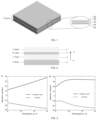
- FIG. 1 is a schematic structural view of the present disclosure, wherein the material indicated by 01 is photoresist, and the material indicated by 02 is indium tin oxide.
- FIG. 2 shows the thickness and material of each of the multilayer film described in the first embodiment of the present disclosure.
- FIG. 3 shows the parameters of indium tin oxide and the photoresist in the infrared band, which are used to simulate the first embodiment of the present disclosure, wherein (a) is the parameter of indium tin oxide, and (b) is the parameter of the photoresist.
- FIG. 4 shows the absorptivity of the multilayer film described in the first embodiment of the present disclosure at different angles.
- FIG. 5 is a graph showing the transmittance of the multilayer film of the present disclosure in the visible band.
- the present disclosure provides a visible light-transparent and radiative-cooling multilayer film, in which a new film layer arrangement is adopted, so that the multilayer film has an extremely high visible light transmittance while achieving radiative cooling.
- a visible light-transparent and radiative-cooling multilayer film comprising N layers of films with different thicknesses.
- the N layers of films with different thicknesses are alternately arranged indium tin oxide (ITO) film layers and photoresist film layers. Since there is a difference between dielectric constants of the two materials, a resonant cavity or resonant cavities may be formed among material layers. The resonant cavity may enhance the electric field therein, thereby increasing the radiance of the structure greatly.
- ITO indium tin oxide
- N 3.
- each of indium tin oxide layers has a thickness of d1, wherein 0.1 ⁇ m ⁇ d1 ⁇ 1 ⁇ m, and each of the photoresist layers has a thickness of d2, wherein 1 ⁇ m ⁇ d2 ⁇ 3 ⁇ m.
- the photoresist is positive photoresist or negative photoresist.
- the photoresist has a refractive index of n1 in visible band, wherein 1.3 ⁇ n1 ⁇ 1.8; the indium tin oxide has a refractive index of n2 in visible band, wherein 1.7 ⁇ n2 ⁇ 2.1.
- the visible light-transparent and radiative-cooling multilayer film comprises indium tin oxide film layers 02 and photoresist film layers 01 with different thicknesses, wherein the indium tin oxide film layers 02 and photoresist film layers 01 are alternately arranged in N layers.
- “radiative cooling” means that objects on the ground achieve cooling by emitting their heat into the space of the universe in the form of electromagnetic waves through thermal radiation.
- electromagnetic waves not all frequencies of electromagnetic waves can be radiated outside the Earth, since the Earth is surrounded by the atmosphere and gases such as water vapor, carbon dioxide and ozone in the atmosphere may absorb electromagnetic waves at specific wavelengths.
- the frequency range with a relatively high atmospheric transmittance is referred to as “atmospheric window”. Radiative cooling can be achieved only when the object radiates at a frequency within the atmospheric window.
- the atmospheric windows between 8-14 ⁇ m is generally concerned, since the wavelengths of black body radiation at normal temperature are mainly in this band. Therefore, when designing a radiative-cooling multilayer film, the multilayer film is required to have an extremely high radiance at 8-14 ⁇ m.
- FIG. 2 shows the thickness and material of each of the multilayer film described in the first embodiment of the present disclosure.
- the photoresist in this embodiment is a commercial photoresist NR5-8000.
- the parameters in the infrared band of indium tin oxide and the photoresist used in the simulation are shown in FIG. 3 .
- the parameters are experimentally measured, wherein FIG. 3 ( a ) is the parameter of indium tin oxide, and FIG. 3 ( b ) is the parameter of the photoresist.
- the radiance of the multilayer film in the infrared band is simulated, wherein the propagation of the incident field is directed from ⁇ z to +z.
- the absorptivity of the multilayer film at different angles is obtained by electromagnetic simulation software, as shown in FIG. 4 .
- the absorptivity of an object is equal to its radiance under a thermal equilibrium state, thus, the absorptivity obtained by simulation is considered to be the radiance of the multilayer film under a thermal equilibrium state.
- the multilayer film has the radiance greater than 90% in the infrared band range of 8-14 ⁇ m.
- the transmittance of the multilayer film in the visible band is simulated by simulation software, as shown in FIG. 5 .
- the refractive index n1 of the photoresist is 1.6
- the refractive index n2 of indium tin oxide is 1.8.
- the multilayer film has a high transparency in the visible band, and the average transmittance of the multilayer film in the visible band is calculated to be 87%.
- the cooling power of the multilayer film is simulated based on the results described above.
- P1 and P2 satisfy the following formulas respectively: P 1 ⁇ d ⁇ cos ⁇ 21 22 d ⁇ I BB ( T , ⁇ ) ⁇ ( ⁇ , ⁇ ) P 2 ⁇ d ⁇ cos ⁇ 21 22 d ⁇ I BB ( T , ⁇ ) ⁇ ( ⁇ , ⁇ ) ⁇ atm ( ⁇ , ⁇ )
- I BB is the blackbody radiation formula expressed by:
- I BB ⁇ ( T , ⁇ ) 2 ⁇ hc 2 ⁇ 5 ⁇ 1 e hc ⁇ / ⁇ ( ⁇ ⁇ ⁇ k B ⁇ T ) - 1
- c represents for the speed of light in vacuum which is 2.998 ⁇ 10 8 m/s
- k B represents for the Boltzmann constant which is 1.38 ⁇ 10 ⁇ 23 J/K
- ⁇ is the corresponding wavelength.
- ⁇ atm ( ⁇ , ⁇ ) 1 ⁇ t( ⁇ ) 1/cos
- ⁇ represents for the radiance of the external environment to the multilayer film
- t( ⁇ ) is the transmittance of the atmospheric window at different wavelengths.
- Table 1 gives the cooling power per unit area of the multilayer film at different ambient temperatures.
- Cooling power per unit area of the multilayer film at different ambient temperatures Ambient temperature (K) Cooling power per unit area (W/m 2 ) 263 72.44 273 87.47 283 104.27 300 137.16
Landscapes
- Engineering & Computer Science (AREA)
- Ceramic Engineering (AREA)
- Physics & Mathematics (AREA)
- Thermal Sciences (AREA)
- Mechanical Engineering (AREA)
- General Engineering & Computer Science (AREA)
- Laminated Bodies (AREA)
- Optical Filters (AREA)
- Surface Treatment Of Glass (AREA)
Abstract
Description
P1∫dΩ cos θΩ21 22 dλI BB(T,λ)ε(λ,θ)
P2∫dΩ cos θΩ21 22 dλI BB(T,λ)ε(λ,θ)εatm(λ,θ)
| TABLE 1 |
| Cooling power per unit area of the multilayer |
| film at different ambient temperatures |
| Ambient temperature (K) | Cooling power per unit area (W/m2) | ||
| 263 | 72.44 | ||
| 273 | 87.47 | ||
| 283 | 104.27 | ||
| 300 | 137.16 | ||
Claims (6)
Applications Claiming Priority (3)
| Application Number | Priority Date | Filing Date | Title |
|---|---|---|---|
| CN201711361964.9A CN108099299B (en) | 2017-12-18 | 2017-12-18 | A Visible Light Transparent Radiation Cooling Multilayer Film |
| CN201711361964.9 | 2017-12-18 | ||
| PCT/CN2018/095780 WO2019119787A1 (en) | 2017-12-18 | 2018-07-16 | Multilayer radiation cooling film transparent to visible light |
Publications (2)
| Publication Number | Publication Date |
|---|---|
| US20210003354A1 US20210003354A1 (en) | 2021-01-07 |
| US11754352B2 true US11754352B2 (en) | 2023-09-12 |
Family
ID=62209747
Family Applications (1)
| Application Number | Title | Priority Date | Filing Date |
|---|---|---|---|
| US16/621,892 Active 2039-10-02 US11754352B2 (en) | 2017-12-18 | 2018-07-16 | Visible light-transparent and radiative-cooling multilayer film |
Country Status (4)
| Country | Link |
|---|---|
| US (1) | US11754352B2 (en) |
| EP (1) | EP3628484B1 (en) |
| CN (1) | CN108099299B (en) |
| WO (1) | WO2019119787A1 (en) |
Families Citing this family (3)
| Publication number | Priority date | Publication date | Assignee | Title |
|---|---|---|---|---|
| CN108099299B (en) | 2017-12-18 | 2020-05-01 | 中国科学院光电技术研究所 | A Visible Light Transparent Radiation Cooling Multilayer Film |
| CN109341137A (en) * | 2018-10-24 | 2019-02-15 | 苏州融睿纳米复材科技有限公司 | Passive refrigeration structure based on photonic crystal |
| CN117073255A (en) * | 2023-08-23 | 2023-11-17 | 郑州大学 | A polarization-controllable color radiation cooling metamaterial and its preparation method and application |
Citations (9)
| Publication number | Priority date | Publication date | Assignee | Title |
|---|---|---|---|---|
| US6451414B1 (en) * | 1998-01-13 | 2002-09-17 | 3M Innovatives Properties Company | Multilayer infrared reflecting optical body |
| US20060267459A1 (en) * | 2005-05-26 | 2006-11-30 | Shelby Marcus D | Micro-coextruded film modified with piezoelectric layers |
| CN102408806A (en) | 2011-11-03 | 2012-04-11 | 浙江大学 | Transparent thermal insulation coating with high emission in atmospheric window area and preparation method thereof |
| WO2015005526A1 (en) | 2013-07-09 | 2015-01-15 | 주식회사 노루페인트 | Energy-saving glass coating composition having contamination resistance, and energy-saving glass structure applying same |
| CN204749422U (en) | 2015-02-04 | 2015-11-11 | 同济大学 | Glass window refrigeration pad pasting based on photonic crystal forbidden band principle |
| CN105957912A (en) | 2016-07-01 | 2016-09-21 | 中国科学技术大学 | Multifunctional spectrum selective encapsulation material |
| CN205900562U (en) | 2016-07-01 | 2017-01-18 | 中国科学技术大学 | Multi -functional spectral selectivity encapsulating material |
| CN108099299A (en) | 2017-12-18 | 2018-06-01 | 中国科学院光电技术研究所 | Visible light transparent radiation refrigeration multilayer film |
| US20180180331A1 (en) * | 2015-06-18 | 2018-06-28 | The Trustees Of Columbia University In The City Of New York | Systems and methods for radiative cooling and heating |
Family Cites Families (4)
| Publication number | Priority date | Publication date | Assignee | Title |
|---|---|---|---|---|
| CN2660413Y (en) * | 2003-11-04 | 2004-12-01 | 黄军华 | Metallic semiconductor refrigerating sheet |
| CN102316619A (en) * | 2011-08-08 | 2012-01-11 | 芜湖日昇昌新光源科技有限公司 | Method for manufacturing large-area electro energy-saving cold light film |
| CN105348892B (en) * | 2015-11-27 | 2017-08-11 | 上海交通大学 | A kind of radiation refrigeration double-layer nanometer coating and preparation method thereof |
| US20170297750A1 (en) * | 2016-04-19 | 2017-10-19 | Palo Alto Research Center Incorporated | Radiative Cooling Panels For Spacecraft |
-
2017
- 2017-12-18 CN CN201711361964.9A patent/CN108099299B/en active Active
-
2018
- 2018-07-16 US US16/621,892 patent/US11754352B2/en active Active
- 2018-07-16 EP EP18890786.9A patent/EP3628484B1/en active Active
- 2018-07-16 WO PCT/CN2018/095780 patent/WO2019119787A1/en not_active Ceased
Patent Citations (10)
| Publication number | Priority date | Publication date | Assignee | Title |
|---|---|---|---|---|
| US6451414B1 (en) * | 1998-01-13 | 2002-09-17 | 3M Innovatives Properties Company | Multilayer infrared reflecting optical body |
| US20060267459A1 (en) * | 2005-05-26 | 2006-11-30 | Shelby Marcus D | Micro-coextruded film modified with piezoelectric layers |
| CN102408806A (en) | 2011-11-03 | 2012-04-11 | 浙江大学 | Transparent thermal insulation coating with high emission in atmospheric window area and preparation method thereof |
| CN102408806B (en) | 2011-11-03 | 2013-10-23 | 浙江大学 | High-emission transparent heat-insulating paint in atmospheric window regions and preparation method thereof |
| WO2015005526A1 (en) | 2013-07-09 | 2015-01-15 | 주식회사 노루페인트 | Energy-saving glass coating composition having contamination resistance, and energy-saving glass structure applying same |
| CN204749422U (en) | 2015-02-04 | 2015-11-11 | 同济大学 | Glass window refrigeration pad pasting based on photonic crystal forbidden band principle |
| US20180180331A1 (en) * | 2015-06-18 | 2018-06-28 | The Trustees Of Columbia University In The City Of New York | Systems and methods for radiative cooling and heating |
| CN105957912A (en) | 2016-07-01 | 2016-09-21 | 中国科学技术大学 | Multifunctional spectrum selective encapsulation material |
| CN205900562U (en) | 2016-07-01 | 2017-01-18 | 中国科学技术大学 | Multi -functional spectral selectivity encapsulating material |
| CN108099299A (en) | 2017-12-18 | 2018-06-01 | 中国科学院光电技术研究所 | Visible light transparent radiation refrigeration multilayer film |
Non-Patent Citations (7)
| Title |
|---|
| "Refractive Index of ITO" (https://www.filmetrics.com/refractive-index-database/ITO/Indium-Tin-Oxide-InSnO:#:˜:text=For%20a%20typical%20sample%20of,nm%20are%201,85844%20and%200.0580774.) (Year: 2022). * |
| "Refractive Index of Polymers" (https://polymerdatabase.com/polymer%20physics/Ref%20Index%20Table2%20.html) (Year: 2022). * |
| Eden Rephaeli et al, "Ultrabroadband Photonic Structures to Achieve High-Performance Daytime Radiative Cooling" Nano Letters, ACS Publications, American Chemical Society, Department of Applied Physics and Department of Electrical Engineering, Stanford University, California,USA, Published; Mar. 5, 2013. |
| International Search Report of the International Searching Authority dated Sep. 28, 2018 for the corresponding International application No. PCT/CN2018/095780 (and English translation). |
| Office Action dated May 8, 2019 issued in corresponding CN patent application No. 201711361964.9 (and English translation). |
| Srinivasan Arvind et al., "Infared dielectric function of polydimethylsiloxane and selective emission behavior" Applied Physics Letters 109, Department of Mechanical Engineering, Columbia University , New York, New York, USA, AIP Publishing LLC, Published online: Aug. 10, 2016. |
| The Extended European Search Report dated Jan. 27, 2021 issued in corresponding EP Application No. 18890786.9. |
Also Published As
| Publication number | Publication date |
|---|---|
| CN108099299A (en) | 2018-06-01 |
| EP3628484A1 (en) | 2020-04-01 |
| EP3628484B1 (en) | 2024-03-27 |
| CN108099299B (en) | 2020-05-01 |
| EP3628484A4 (en) | 2021-02-24 |
| WO2019119787A1 (en) | 2019-06-27 |
| US20210003354A1 (en) | 2021-01-07 |
| EP3628484C0 (en) | 2024-03-27 |
Similar Documents
| Publication | Publication Date | Title |
|---|---|---|
| Jeong et al. | Field investigation of a photonic multi-layered TiO2 passive radiative cooler in sub-tropical climate | |
| Li et al. | Printable, emissivity-adaptive and albedo-optimized covering for year-round energy saving | |
| Li et al. | Wearable janus‐type film with integrated all‐season active/passive thermal management, thermal camouflage, and ultra‐high electromagnetic shielding efficiency tunable by origami process | |
| Kong et al. | Ultra-broadband all-dielectric metamaterial thermal emitter for passive radiative cooling | |
| Cui et al. | Progress of passive daytime radiative cooling technologies towards commercial applications | |
| Li et al. | Janus interface engineering boosting visibly transparent radiative cooling for energy saving | |
| Yin et al. | Switchable kirigami structures as window envelopes for energy-efficient buildings | |
| US11754352B2 (en) | Visible light-transparent and radiative-cooling multilayer film | |
| CN110567188A (en) | Winter and summer temperature adjusting device based on radiation cooling and solar energy utilization and construction method | |
| Wang et al. | Switchable daytime radiative cooling and nighttime radiative warming by VO2 | |
| Liu et al. | Ultra-broadband infrared metamaterial absorber for passive radiative cooling | |
| Dai et al. | Radiative cooling with multilayered periodic grating under sunlight | |
| Wang et al. | Fundamental concepts, design rules and potentials in radiative cooling | |
| CN104198051A (en) | Multiband infrared metamaterial wave absorber | |
| CN111883936A (en) | Terahertz electromagnetic absorber based on metamaterial | |
| Hu et al. | Theoretical investigation of VO2 smart window with large-scale dynamic infrared emittance adjustment for adaptive thermal management | |
| Li et al. | Integration of daytime radiative cooling and solar heating | |
| AU2025205150A1 (en) | Beam-controlled spectral-selective architecture for a radiative cooler | |
| Li et al. | Ultra-broadband thermal radiator for daytime passive radiative cooling based on single dielectric SiO2 on metal Ag | |
| Alimohammadian et al. | Innovative strategy of passive sub-ambient radiative cooler through incorporation of a thermal rectifier to double-layer nanoparticle-based coating | |
| Chen et al. | Wavelength-selective thermal nonreciprocity barely improves sky radiative cooling | |
| Ryu et al. | Angular selective broadband radiative cooling based on Berreman mode | |
| CN111690382A (en) | Transmission type radiation refrigeration inorganic material | |
| CN114501969B (en) | A highly transmittance heat-adjustable microwave absorption window based on thermotropic phase change material | |
| Ming et al. | A generalized solar and thermal management strategy for daytime radiative cooling |
Legal Events
| Date | Code | Title | Description |
|---|---|---|---|
| AS | Assignment |
Owner name: THE INSTITUTE OF OPTICS AND ELECTRONICS, THE CHINESE ACADEMY OF SCIENCES, CHINA Free format text: ASSIGNMENT OF ASSIGNORS INTEREST;ASSIGNORS:LUO, XIANGANG;MA, XIAOLIANG;PU, MINGBO;AND OTHERS;REEL/FRAME:051271/0681 Effective date: 20191205 |
|
| FEPP | Fee payment procedure |
Free format text: ENTITY STATUS SET TO UNDISCOUNTED (ORIGINAL EVENT CODE: BIG.); ENTITY STATUS OF PATENT OWNER: SMALL ENTITY |
|
| FEPP | Fee payment procedure |
Free format text: ENTITY STATUS SET TO SMALL (ORIGINAL EVENT CODE: SMAL); ENTITY STATUS OF PATENT OWNER: SMALL ENTITY |
|
| STPP | Information on status: patent application and granting procedure in general |
Free format text: APPLICATION DISPATCHED FROM PREEXAM, NOT YET DOCKETED |
|
| STPP | Information on status: patent application and granting procedure in general |
Free format text: DOCKETED NEW CASE - READY FOR EXAMINATION |
|
| STPP | Information on status: patent application and granting procedure in general |
Free format text: NON FINAL ACTION MAILED |
|
| STPP | Information on status: patent application and granting procedure in general |
Free format text: RESPONSE TO NON-FINAL OFFICE ACTION ENTERED AND FORWARDED TO EXAMINER |
|
| STPP | Information on status: patent application and granting procedure in general |
Free format text: FINAL REJECTION MAILED |
|
| STPP | Information on status: patent application and granting procedure in general |
Free format text: DOCKETED NEW CASE - READY FOR EXAMINATION |
|
| STPP | Information on status: patent application and granting procedure in general |
Free format text: NOTICE OF ALLOWANCE MAILED -- APPLICATION RECEIVED IN OFFICE OF PUBLICATIONS |
|
| STPP | Information on status: patent application and granting procedure in general |
Free format text: PUBLICATIONS -- ISSUE FEE PAYMENT VERIFIED |
|
| STCF | Information on status: patent grant |
Free format text: PATENTED CASE |