US11753045B2 - Modeling positional uncertainty of moving objects using precomputed polygons - Google Patents
Modeling positional uncertainty of moving objects using precomputed polygons Download PDFInfo
- Publication number
- US11753045B2 US11753045B2 US17/354,614 US202117354614A US11753045B2 US 11753045 B2 US11753045 B2 US 11753045B2 US 202117354614 A US202117354614 A US 202117354614A US 11753045 B2 US11753045 B2 US 11753045B2
- Authority
- US
- United States
- Prior art keywords
- polygon
- lateral
- precomputed
- along
- vertices
- Prior art date
- Legal status (The legal status is an assumption and is not a legal conclusion. Google has not performed a legal analysis and makes no representation as to the accuracy of the status listed.)
- Active, expires
Links
Images


Classifications
-
- B—PERFORMING OPERATIONS; TRANSPORTING
- B60—VEHICLES IN GENERAL
- B60W—CONJOINT CONTROL OF VEHICLE SUB-UNITS OF DIFFERENT TYPE OR DIFFERENT FUNCTION; CONTROL SYSTEMS SPECIALLY ADAPTED FOR HYBRID VEHICLES; ROAD VEHICLE DRIVE CONTROL SYSTEMS FOR PURPOSES NOT RELATED TO THE CONTROL OF A PARTICULAR SUB-UNIT
- B60W60/00—Drive control systems specially adapted for autonomous road vehicles
- B60W60/001—Planning or execution of driving tasks
- B60W60/0027—Planning or execution of driving tasks using trajectory prediction for other traffic participants
- B60W60/00274—Planning or execution of driving tasks using trajectory prediction for other traffic participants considering possible movement changes
-
- B—PERFORMING OPERATIONS; TRANSPORTING
- B60—VEHICLES IN GENERAL
- B60W—CONJOINT CONTROL OF VEHICLE SUB-UNITS OF DIFFERENT TYPE OR DIFFERENT FUNCTION; CONTROL SYSTEMS SPECIALLY ADAPTED FOR HYBRID VEHICLES; ROAD VEHICLE DRIVE CONTROL SYSTEMS FOR PURPOSES NOT RELATED TO THE CONTROL OF A PARTICULAR SUB-UNIT
- B60W30/00—Purposes of road vehicle drive control systems not related to the control of a particular sub-unit, e.g. of systems using conjoint control of vehicle sub-units, or advanced driver assistance systems for ensuring comfort, stability and safety or drive control systems for propelling or retarding the vehicle
- B60W30/08—Active safety systems predicting or avoiding probable or impending collision or attempting to minimise its consequences
- B60W30/09—Taking automatic action to avoid collision, e.g. braking and steering
-
- B—PERFORMING OPERATIONS; TRANSPORTING
- B60—VEHICLES IN GENERAL
- B60W—CONJOINT CONTROL OF VEHICLE SUB-UNITS OF DIFFERENT TYPE OR DIFFERENT FUNCTION; CONTROL SYSTEMS SPECIALLY ADAPTED FOR HYBRID VEHICLES; ROAD VEHICLE DRIVE CONTROL SYSTEMS FOR PURPOSES NOT RELATED TO THE CONTROL OF A PARTICULAR SUB-UNIT
- B60W30/00—Purposes of road vehicle drive control systems not related to the control of a particular sub-unit, e.g. of systems using conjoint control of vehicle sub-units, or advanced driver assistance systems for ensuring comfort, stability and safety or drive control systems for propelling or retarding the vehicle
- B60W30/08—Active safety systems predicting or avoiding probable or impending collision or attempting to minimise its consequences
- B60W30/095—Predicting travel path or likelihood of collision
-
- B—PERFORMING OPERATIONS; TRANSPORTING
- B60—VEHICLES IN GENERAL
- B60W—CONJOINT CONTROL OF VEHICLE SUB-UNITS OF DIFFERENT TYPE OR DIFFERENT FUNCTION; CONTROL SYSTEMS SPECIALLY ADAPTED FOR HYBRID VEHICLES; ROAD VEHICLE DRIVE CONTROL SYSTEMS FOR PURPOSES NOT RELATED TO THE CONTROL OF A PARTICULAR SUB-UNIT
- B60W60/00—Drive control systems specially adapted for autonomous road vehicles
- B60W60/001—Planning or execution of driving tasks
- B60W60/0027—Planning or execution of driving tasks using trajectory prediction for other traffic participants
- B60W60/00272—Planning or execution of driving tasks using trajectory prediction for other traffic participants relying on extrapolation of current movement
-
- B—PERFORMING OPERATIONS; TRANSPORTING
- B60—VEHICLES IN GENERAL
- B60W—CONJOINT CONTROL OF VEHICLE SUB-UNITS OF DIFFERENT TYPE OR DIFFERENT FUNCTION; CONTROL SYSTEMS SPECIALLY ADAPTED FOR HYBRID VEHICLES; ROAD VEHICLE DRIVE CONTROL SYSTEMS FOR PURPOSES NOT RELATED TO THE CONTROL OF A PARTICULAR SUB-UNIT
- B60W2554/00—Input parameters relating to objects
- B60W2554/40—Dynamic objects, e.g. animals, windblown objects
- B60W2554/404—Characteristics
-
- B—PERFORMING OPERATIONS; TRANSPORTING
- B60—VEHICLES IN GENERAL
- B60W—CONJOINT CONTROL OF VEHICLE SUB-UNITS OF DIFFERENT TYPE OR DIFFERENT FUNCTION; CONTROL SYSTEMS SPECIALLY ADAPTED FOR HYBRID VEHICLES; ROAD VEHICLE DRIVE CONTROL SYSTEMS FOR PURPOSES NOT RELATED TO THE CONTROL OF A PARTICULAR SUB-UNIT
- B60W2720/00—Output or target parameters relating to overall vehicle dynamics
- B60W2720/24—Direction of travel
Definitions
- the instant specification generally relates to autonomous vehicles. More specifically, the instant specification relates to predicting trajectories of detected objects in autonomous driving environments.
- An autonomous (fully and partially self-driving) vehicle operates by sensing an outside environment with various electromagnetic (e.g., radar and optical) and non-electromagnetic (e.g., audio and humidity) sensors.
- Some autonomous vehicles chart a driving path through the environment based on the sensed data.
- Precision and safety of the driving path and of the speed regime selected by the autonomous vehicle depend significantly on timely and accurate identification of various objects present in the driving environment, and on the ability of a driving algorithm to quickly and efficiently process the information about the environment and provide correct instructions to the vehicle controls and the drivetrain.
- Such computations can be performed by modeling the uncertainty of an object's behavior, such as lateral uncertainty relative to its traveling direction.
- FIG. 1 is a diagram illustrating components of an example autonomous vehicle that uses Doppler-assisted object identification and tracking, in accordance with some implementations of the present disclosure.
- FIG. 2 is an illustration of a Doppler-assisted object identification and tracking setup that utilizes velocity reconstruction, as part of a perception system of an autonomous vehicle, in accordance with some implementations of the present disclosure.
- FIG. 3 is an illustration of a velocity reconstruction setup, as part of a perception system of an autonomous vehicle, in accordance with some implementations of the present disclosure.
- FIG. 4 is an illustration of an agent state representative of an object in accordance with some implementations of the present disclosure.
- FIG. 5 A illustrates an AV trajectory as a series of overlapping states in accordance with some implementations of the present disclosure.
- FIG. 5 B illustrates an agent state overlapping with the AV trajectory in accordance with some implementations of the present disclosure.
- FIG. 6 A illustrates geometric parameters of overlap between an AV and an agent state in accordance with some implementations of the present disclosure.
- FIG. 6 B illustrates geometric parameters for partial overlap between the AV and the agent state in accordance with some implementations of the present disclosure.
- FIG. 6 C illustrates a first example of interpolation of the overlap region based on updated lateral bounds of the agent state in accordance with some implementations of the present disclosure.
- FIG. 6 D illustrates a second example of interpolation of the overlap region based on updated lateral bounds of the agent state in accordance with some implementations of the present disclosure.
- FIG. 7 depicts a flow diagram of an example method of using a box-shaped probabilistic overlap module to control a trajectory of an AV in accordance with some implementations of the present disclosure.
- FIG. 8 illustrates an exemplary polygon representative of an agent state of an object or a probabilistic overlap region in accordance with some implementations of the present disclosure.
- FIG. 9 A illustrates a front portion and a rear portion of the polygon to which an expansion transformation is to be applied in accordance with some implementations of the present disclosure.
- FIG. 9 B illustrates applying an expansion transformation to the polygon along a longitudinal axis in accordance with some implementations of the present disclosure.
- FIG. 9 C illustrates applying a further expansion transformation to the polygon along a lateral axis to generate a precomputed polygon in accordance with some implementations of the present disclosure.
- FIG. 10 depicts a flow diagram of an example method of generating a precomputed polygon for modeling positional uncertainty in a moving object in accordance with some implementations of the present disclosure.
- FIG. 11 depicts a block diagram of an example computer device for use in accordance with some implementations of the disclosure.
- a method comprises: receiving, by a data processing system of an autonomous vehicle (AV), data descriptive of an agent state of an object or a probabilistic overlap between the agent state and a trajectory of the AV; generating a polygon representative of the agent state or the probabilistic overlap; identifying extreme vertices of the polygon along a longitudinal axis parallel to a heading direction of the object or along a lateral axis orthogonal to the heading direction; and applying, based on the extreme vertices, at least one expansion transformation to the polygon along the longitudinal axis or the lateral axis to generate a precomputed polygon.
- a driving path or a speed of the AV is modified based on the precomputed polygon.
- identifying the extreme vertices of the polygon comprises: identifying longitudinal extreme vertices of the polygon along the longitudinal axis; and identifying lateral extreme vertices of the polygon along the lateral axis.
- applying the at least one expansion transformation to the polygon along the longitudinal axis or the lateral axis comprises: applying a first expansion transformation to the polygon along the longitudinal axis to duplicate each lateral extreme vertex; and applying a second expansion transformation to the polygon along the lateral axis to duplicate each longitudinal extreme vertex.
- the method further comprises applying at least one additional expansion transformation to the precomputed polygon based on an uncertainty of the agent state. In at least one implementation, a total number of vertices of the precomputed polygon is unchanged by the additional expansion transformation.
- the at least one additional expansion transformation is applied to the precomputed polygon responsive to the data processing system receiving a query from a control system of the AV, the query indicating a level of risk tolerance with respect to the agent state.
- the method further comprises transmitting, to the control system, data representative of uncertainty in a longitudinal position and a lateral position of the object computed based on the precomputed polygon.
- the control system is to modify the driving path or the speed of the AV based on the data representative of uncertainty in the longitudinal position and the lateral position.
- the method further comprises computing a trajectory of the object comprising a series of agent states that includes the agent state of the object.
- the precomputed polygon is used to model each agent state in the series of agent states.
- a system comprises: a memory; and a data processing system of an AV communicatively coupled to the memory.
- the data processing system is to: receive data descriptive of an agent state of an object or a probabilistic overlap between the agent state and a trajectory of the AV; generate a polygon representative of the agent state or the probabilistic overlap; identify extreme vertices of the polygon along a longitudinal axis parallel to a heading direction of the object or along a lateral axis orthogonal to the heading direction; and apply, based on the extreme vertices, at least one expansion transformation to the polygon along the longitudinal axis or the lateral axis to generate a precomputed polygon.
- a driving path or a speed of the AV is to be modified based on the precomputed polygon.
- the data processing system is to: identify longitudinal extreme vertices of the polygon along the longitudinal axis; and identify lateral extreme vertices of the polygon along the lateral axis.
- the data processing system is to: apply a first expansion transformation to the polygon along the longitudinal axis to duplicate each lateral extreme vertex; and apply a second expansion transformation to the polygon along the lateral axis to duplicate each longitudinal extreme vertex.
- the data processing system is to further apply at least one additional expansion transformation to the precomputed polygon based on an uncertainty of the agent state.
- a total number of vertices of the precomputed polygon is unchanged by the additional expansion transformation.
- At least one additional expansion transformation is to be applied to the precomputed polygon responsive to the data processing system receiving a query from a control system of the AV, the query indicating a level of risk tolerance with respect to the agent state.
- the data processing system is to further transmit, to the control system, data representative of uncertainty in a longitudinal position and a lateral position of the object computed based on the precomputed polygon.
- the control system is to modify the driving path or the speed of the AV based on the data representative of uncertainty in the longitudinal position and the lateral position.
- the data processing system is to further compute a trajectory of the object comprising a series of agent states that includes the agent state of the object.
- the precomputed polygon is to be used to model each agent state in the series of agent states.
- a non-transitory computer-readable medium has instructions stored thereon that, when executed by a computing device, cause the computing device to perform any implementation of the method described above.
- An autonomous vehicle can employ various technologies and data sources for identifying static and moving objects within or near a roadway, such as a light detection and ranging (LiDAR) technology for detecting distances to and velocities of various objects, as well as radar devices, sonar devices, cameras, global position system (GPS) data, and roadway map data. Signals obtained by various sensing devices can be used in conjunction with other data by an on-board data processing system of the AV to identify relevant objects, determine their locations and velocities, classify those objects, and predict their behavior. Object data is monitored and updated in real-time, and is utilized by an AV control system to determine how the AV is to safely and legally navigate the roadway.
- LiDAR light detection and ranging
- GPS global position system
- Some AV data processing systems and control systems utilize algorithms to predict how the objects overlap with the AV's trajectory in order to compute a safe driving trajectory.
- Such algorithms model the object's behavior based on uncertainty along certain directions.
- the object may have a longitudinal uncertainty defined along the direction of its traveling direction (e.g., instantaneous velocity).
- the object may also have a lateral uncertainty along the direction orthogonal to its traveling direction.
- the object's predicted trajectory may be represented, for example, as a sequence of “agent states” each representing a position in time of the object, a direction of motion or heading of the object, and an uncertainty profile along lateral and longitudinal directions of the object.
- the object's uncertainty may be modeled, for example, by a Gaussian distribution characterized by a mean position and a standard deviation from the mean position.
- Probabilistic overlaps can be computed between the AV and the agent state in order to estimate the risk of collisions between the AV and the object.
- the overlap may be computed based on different lateral uncertainties, with each lateral uncertainty being representative of a risk tolerance for maneuverability of the AV.
- probabilistic overlaps may be computed by using a polygon trajectory overlap computation method, storing each overlap, and performing linear interpolations. This method may involve constructing a polygon including the agent's lateral bounds followed by computing the overlap between the extended polygon and the trajectory of the AV. While such methods can accurately compute and model the probabilistic overlap, they are usually computationally intensive and time-consuming.
- Polygon precomputation can be used to precompute angles of polygons representative of agent states and probabilistic overlaps so that extreme points of the polygon can be identified quickly without requiring computationally expensive trigonometric calculations to recompute angles when the polygon is rotated.
- the polygon need only be translated and rotated without changing the shape of the polygon, thus allowing for a precomputed polygon to be reused at each point along the trajectory.
- the expansion of the polygon occurs in four directions: two opposing directions oriented along the object heading (a longitudinal axis), and two opposing directions oriented a lateral axis (orthogonal to the longitudinal axis).
- computing the probabilistic overlap is a two-step process where (1) a parallelogram corresponding to maximum uncertainty in the lateral position of the object is computed, and (2) the parallelogram is interpolated based on lateral bounds representative of a particular amount of risk tolerance for maneuvering the AV. In certain scenarios, such as narrow streets, or crowded environments, the lateral bounds may be reduced (which is equivalent to higher risk tolerance) to determine, for example, if the AV can safely navigate past the object.
- aspects of the present disclosure address problems related to AV trajectory planning, namely how to efficiently compute probabilistic overlaps between the AV and an agent state of an object trajectory.
- the AV (or state of the AV) and the agent state are each modeled by boxes. Based on a pair of lateral bounds for the agent state, a probabilistic overlap can be computed. This approach is advantageously faster than prior approaches utilizing more complex geometries by a factor on the order of 100.
- the probabilistic overlap representing maximum uncertainty is calculated and cached.
- the cached probabilistic overlap can be advantageously used in subsequent calculations based on a narrower set of lateral bounds by interpolating the probabilistic overlap shape using the narrower set of lateral bounds. Interpolation is faster by a factor of about 1.3 than re-calculation of the overlap and achieves the same accuracy, thus supporting multiple overlap queries efficiently.
- aspects of the present disclosure address problems related to applying expansion transformations to polygons representative of agent states or probabilistic overlaps to model longitudinal and lateral uncertainties.
- the implementations herein provide a method to expand the polygon in lateral and longitudinal direction to generate a precomputed polygon that preserves angular information of the original polygon.
- an initially generated polygon is expanded by first identifying extreme vertices along the longitudinal and lateral axes of the polygon. The polygon is then shifted along each axis by a unit or nominal distance, resulting in duplication of the identified extreme vertices and expandable edges between each extreme vertex and its corresponding duplicate.
- the same precomputed polygon may be used to quickly compute extreme vertices of the expanded polygon to which the shifts are applied.
- Advantages of the implementations described herein include, but are not limited to: (1) use of the precomputed polygon in subsequent calculations allowing for translations, rotations, and expansions without requiring angle recalculations; (2) reuse of the precomputed polygon to model each frame of the object's trajectory; and (3) efficient modeling of longitudinal and lateral uncertainty for any arbitrary object or probabilistic overlap shape.
- FIG. 1 is a diagram illustrating components of an example autonomous vehicle (AV) 100 that uses Doppler-assisted object identification and tracking, in accordance with some implementations of the present disclosure.
- FIG. 1 illustrates operations of the example autonomous vehicle.
- Autonomous vehicles can include motor vehicles (cars, trucks, buses, motorcycles, all-terrain vehicles, recreational vehicle, any specialized farming or construction vehicles, and the like), aircraft (planes, helicopters, drones, and the like), naval vehicles (ships, boats, yachts, submarines, and the like), or any other self-propelled vehicles (e.g., sidewalk delivery robotic vehicles) capable of being operated in a self-driving mode (without a human input or with a reduced human input).
- motor vehicles cars, trucks, buses, motorcycles, all-terrain vehicles, recreational vehicle, any specialized farming or construction vehicles, and the like
- aircraft planes, helicopters, drones, and the like
- naval vehicles ships, boats, yachts, submarines, and the like
- a driving environment 110 can include any objects (animated or non-animated) located outside the AV, such as roadways, buildings, trees, bushes, sidewalks, bridges, mountains, other vehicles, pedestrians, and so on.
- the driving environment 110 can be urban, suburban, rural, and so on.
- the driving environment 110 can be an off-road environment (e.g., farming or agricultural land).
- the driving environment can be an indoor environment, e.g., the environment of an industrial plant, a shipping warehouse, a hazardous area of a building, and so on.
- the driving environment 110 can be substantially flat, with various objects moving parallel to a surface (e.g., parallel to the surface of Earth).
- the driving environment can be three-dimensional and can include objects that are capable of moving along all three directions (e.g., balloons, leaves, etc.).
- driving environment should be understood to include all environments in which an autonomous motion of self-propelled vehicles can occur.
- driving environment can include any possible flying environment of an aircraft or a marine environment of a naval vessel.
- the objects of the driving environment 110 can be located at any distance from the AV, from close distances of several feet (or less) to several miles (or more).
- the example AV 100 can include a sensing system 120 .
- the sensing system 120 can include various electromagnetic (e.g., optical) and non-electromagnetic (e.g., acoustic) sensing subsystems and/or devices.
- electromagnetic and non-electromagnetic e.g., acoustic sensing subsystems and/or devices.
- the terms “optical” and “light,” as referenced throughout this disclosure, are to be understood to encompass any electromagnetic radiation (waves) that can be used in object sensing to facilitate autonomous driving, e.g., distance sensing, velocity sensing, acceleration sensing, rotational motion sensing, and so on.
- optical sensing can utilize a range of light visible to a human eye (e.g., the 380 to 700 nm wavelength range), the UV range (below 380 nm), the infrared range (above 700 nm), the radio frequency range (above 1 m), etc.
- optical and “light” can include any other suitable range of the electromagnetic spectrum.
- the sensing system 120 can include a radar unit 126 , which can be any system that utilizes radio or microwave frequency signals to sense objects within the driving environment 110 of the AV 100 .
- the radar unit can be configured to sense both the spatial locations of the objects (including their spatial dimensions) and their velocities (e.g., using the Doppler shift technology).
- velocity refers to both how fast the object is moving (the speed of the object) as well as the direction of the object's motion.
- angular velocity refers to how fast the object is rotating around some axis as well as the direction of this axis of rotation. For example, a car that is making a left (right) turn has the axis of rotation pointed up (down) and the value of the angular velocity is equal to the rate of change of the angle of rotation (e.g., measured in radians per second).
- the sensing system 120 can include one or more LiDAR sensors 122 (e.g., LiDAR rangefinders), which can be a laser-based unit capable of determining distances (e.g., using ToF technology) to the objects in the driving environment 110 .
- the LiDAR sensor(s) 122 can utilize wavelengths of electromagnetic waves that are shorter than the wavelength of the radio waves and can, therefore, provide a higher spatial resolution and sensitivity compared with the radar unit.
- the LiDAR sensor(s) 122 can include a coherent LiDAR sensor, such as a frequency-modulated continuous wave (FMCW) LiDAR sensor.
- FMCW frequency-modulated continuous wave
- the LiDAR sensor(s) 122 can use optical heterodyne detection for velocity determination.
- the functionality of ToF and coherent LiDAR sensor(s) is combined into a single (e.g., hybrid) unit capable of determining both the distance to and the radial velocity of the reflecting object.
- a hybrid unit can be configured to operate in an incoherent sensing mode (ToF mode) and/or a coherent sensing mode (e.g., a mode that uses heterodyne detection) or both modes at the same time.
- multiple LiDAR sensor(s) 122 can be mounted on AV, e.g., at different locations separated in space, to provide additional information about a transverse component of the velocity of the reflecting object, as described in more detail below.
- the LiDAR sensor(s) 122 can include one or more laser sources producing and emitting signals and one or more detectors of the signals reflected back from the objects.
- the LiDAR sensor(s) 122 can include spectral filters to filter out spurious electromagnetic waves having wavelengths (frequencies) that are different from the wavelengths (frequencies) of the emitted signals.
- the LiDAR sensor(s) 122 can include directional filters (e.g., apertures, diffraction gratings, and so on) to filter out electromagnetic waves that can arrive at the detectors along directions different from the retro-reflection directions for the emitted signals.
- the LiDAR sensor(s) 122 can use various other optical components (lenses, mirrors, gratings, optical films, interferometers, spectrometers, local oscillators, and the like) to enhance sensing capabilities of the sensors.
- the LiDAR sensor(s) 122 can be 360-degree unit in a horizontal direction. In some implementations, the LiDAR sensor(s) 122 can be capable of spatial scanning along both the horizontal and vertical directions. In some implementations, the field of view can be up to 90 degrees in the vertical direction (so that at least a part of the upper hemisphere is covered by the LiDAR signals). In some implementations, the field of view can be a full sphere (consisting of two hemispheres).
- LiDAR technology LiDAR sensing
- LiDAR data LiDAR data
- LiDAR LiDAR data
- the sensing system 120 can further include one or more cameras 129 to capture images of the driving environment 110 .
- the images can be two-dimensional projections of the driving environment 110 (or parts of the driving environment 110 ) onto a projecting plane (flat or non-flat, e.g. fisheye) of the cameras.
- Some of the cameras 129 of the sensing system 120 can be video cameras configured to capture a continuous (or quasi-continuous) stream of images of the driving environment 110 .
- the sensing system 120 can also include one or more sonars 128 , which can be ultrasonic sonars, in some implementations.
- the sensing data obtained by the sensing system 120 can be processed by a data processing system 130 of AV 100 .
- the data processing system 130 can include a perception system 132 .
- the perception system 132 can be configured to detect and track objects in the driving environment 110 and to recognize the detected objects.
- the perception system 132 can analyze images captured by the cameras 129 and can be capable of detecting traffic light signals, road signs, roadway layouts (e.g., boundaries of traffic lanes, topologies of intersections, designations of parking places, and so on), presence of obstacles, and the like.
- the perception system 132 can further receive the LiDAR sensing data (coherent Doppler data and incoherent ToF data) to determine distances to various objects in the environment 110 and velocities (radial and, in some implementations, transverse) of such objects.
- the perception system 132 can use the LiDAR data in combination with the data captured by the camera(s) 129 .
- the camera(s) 129 can detect an image of a rock partially obstructing a traffic lane.
- the perception system 132 can be capable of determining the angular size of the rock, but not the linear size of the rock.
- the perception system 132 can determine the distance from the rock to the AV and, therefore, by combining the distance information with the angular size of the rock, the perception system 132 can determine the linear dimensions of the rock as well.
- the perception system 132 can determine how far a detected object is from the AV and can further determine the component of the object's velocity along the direction of the AV's motion. Furthermore, using a series of quick images obtained by the camera, the perception system 132 can also determine the lateral velocity of the detected object in a direction perpendicular to the direction of the AV's motion. In some implementations, the lateral velocity can be determined from the LiDAR data alone, for example, by recognizing an edge of the object (using horizontal scanning) and further determining how quickly the edge of the object is moving in the lateral direction. In some implementations, the perception system 132 can receive one or more sensor data frames from the sensing system 120 . Each of the sensor frames can include multiple points.
- Each point can correspond to a reflecting surface from which a signal emitted by the sensing system 120 (e.g., by LiDAR sensor(s) 122 ) is reflected.
- the type and/or nature of the reflecting surface can be unknown.
- Each point can be associated with various data, such as a timestamp of the frame, coordinates of the reflecting surface, radial velocity of the reflecting surface, intensity of the reflected signal, and so on.
- the coordinates can be spherical (or cylindrical) coordinates, in one implementation.
- the coordinates can include the radial distance, the polar angle (the angle the direction to the respective reflecting surface makes with the vertical direction or a horizontal plane), and the azimuthal angle (the angle indicating the direction within the horizontal plane).
- the radial distance can be determined from the LiDAR data whereas the angles can be independently known from synchronizer data or clock data, e.g., based on the known frequency of rotation of the transmitter within the horizontal plane.
- the perception system 132 can use one or more algorithms to process, classify, and filter various sets of points, which can be used by the perception system 132 for efficient and reliable detection and tracking of objects.
- the perception system 132 can further receive information from a GPS transceiver (not shown) configured to obtain information about the position of the AV relative to Earth.
- the GPS data processing module 134 can use the GPS data in conjunction with the sensing data to help accurately determine location of the AV with respect to fixed objects of the driving environment 110 , such as roadways, lane boundaries, intersections, sidewalks, crosswalks, road signs, surrounding buildings, and so on, locations of which can be provided by map information 135 .
- the data processing system 130 can receive non-electromagnetic data, such as sonar data (e.g., ultrasonic sensor data), temperature sensor data, pressure sensor data, meteorological data (e.g., wind speed and direction, precipitation data), and the like.
- the data processing system 130 can further include an environment monitoring and prediction component 136 , which can monitor how the driving environment 110 evolves with time, e.g., by keeping track of the locations and velocities of the animated objects (relative to Earth).
- the environment monitoring and prediction component 136 can keep track of the changing appearance of the environment due to motion of the AV relative to the environment.
- the environment monitoring and prediction component 136 can make predictions about how various animated objects of the driving environment 110 will be positioned within a prediction time horizon. The predictions can be based on the current locations and velocities of the animated objects as well as on the tracked dynamics of the animated objects during a certain (e.g., predetermined) period of time.
- the environment monitoring and prediction component 136 can conclude that object 1 is resuming its motion from a stop sign or a red traffic light signal. Accordingly, the environment monitoring and prediction component 136 can predict, given the layout of the roadway and presence of other vehicles, where object 1 is likely to be within the next 3 or 5 seconds of motion. As another example, based on stored data for object 2 indicating decelerated motion of object 2 during the previous 2-second period of time, the environment monitoring and prediction component 136 can conclude that object 2 is stopping at a stop sign or at a red traffic light signal. Accordingly, the environment monitoring and prediction component 136 can predict where object 2 is likely to be within the next 1 or 3 seconds. The environment monitoring and prediction component 136 can perform periodic checks of the accuracy of its predictions and modify the predictions based on new data obtained from the sensing system 120 .
- the environmental monitoring and prediction component 136 may utilize a probabilistic overlap module 137 to compute probabilistic overlaps between the AV and an agent state of nearby objects in order to estimate the risk of collisions between the AV and the objects.
- the probabilistic overlap module 137 computes and caches a probabilistic overlap between the AV and objects identified, for example, by the perception system 132 .
- the probabilistic overlap module 137 may further compute uncertainty in positions of the objects based on the cached probabilistic overlap in response to queries received, for example, from an AV control system (AVCS) 140 (described in greater detail below).
- AVCS AV control system
- the data generated by the perception system 132 , the GPS data processing module 134 , and the environment monitoring and prediction component 136 can be used by an autonomous driving system, such as the AV control system (AVCS) 140 .
- the AVCS 140 can include one or more algorithms that control how AV is to behave in various driving situations and environments.
- the AVCS 140 can include a navigation system for determining a global driving route to a destination point.
- the AVCS 140 can also include a driving path selection system for selecting a particular path through the immediate driving environment, which can include selecting a traffic lane, negotiating a traffic congestion, choosing a place to make a U-turn, selecting a trajectory for a parking maneuver, and so on.
- the AVCS 140 can also include an obstacle avoidance system for safe avoidance of various obstructions (rocks, stalled vehicles, a jaywalking pedestrian, and so on) within the driving environment of the AV.
- the obstacle avoidance system can be configured to evaluate the size of the obstacles and the trajectories of the obstacles (if obstacles are animated) and select an optimal driving strategy (e.g., braking, steering, accelerating, etc.) for avoiding the obstacles.
- Algorithms and modules of AVCS 140 can generate instructions for various systems and components of the vehicle, such as the powertrain and steering 150 , vehicle electronics 160 , signaling 170 , and other systems and components not explicitly shown in FIG. 1 .
- the powertrain and steering 150 can include an engine (internal combustion engine, electric engine, and so on), transmission, differentials, axles, wheels, steering mechanism, and other systems.
- the vehicle electronics 160 can include an on-board computer, engine management, ignition, communication systems, carputers, telematics, in-car entertainment systems, and other systems and components.
- the signaling 170 can include high and low headlights, stopping lights, turning and backing lights, horns and alarms, inside lighting system, dashboard notification system, passenger notification system, radio and wireless network transmission systems, and so on. Some of the instructions output by the AVCS 140 can be delivered directly to the powertrain and steering 150 (or signaling 170 ) whereas other instructions output by the AVCS 140 are first delivered to the vehicle electronics 160 , which generate commands to the powertrain and steering 150 and/or signaling 170 .
- the AVCS 140 can determine that an obstacle identified by the data processing system 130 is to be avoided by decelerating the vehicle until a safe speed is reached, followed by steering the vehicle around the obstacle.
- the AVCS 140 can output instructions to the powertrain and steering 150 (directly or via the vehicle electronics 160 ) to (1) reduce, by modifying the throttle settings, a flow of fuel to the engine to decrease the engine rpm, (2) downshift, via an automatic transmission, the drivetrain into a lower gear, (3) engage a brake unit to reduce (while acting in concert with the engine and the transmission) the vehicle's speed until a safe speed is reached, and (4) perform, using a power steering mechanism, a steering maneuver until the obstacle is safely bypassed. Subsequently, the AVCS 140 can output instructions to the powertrain and steering 150 to resume the previous speed settings of the vehicle.
- FIG. 2 is an illustration 200 of a Doppler-assisted object identification and tracking setup that utilizes velocity reconstruction, as part of a perception system of an autonomous vehicle, in accordance with some implementations of the present disclosure.
- AV 202 which can be AV 100 or any other AV
- the AV 202 has a sensor 206 , which can be a LiDAR, such as a coherent LiDAR, an FMCW LiDAR, a hybrid coherent/ToF LiDAR, a combination of a coherent and incoherent LiDAR. etc., or any other device that allows to sense the radial velocity information in addition to the range (distance) information (e.g., the LiDAR sensor(s) 122 ).
- LiDAR such as a coherent LiDAR, an FMCW LiDAR, a hybrid coherent/ToF LiDAR, a combination of a coherent and incoherent LiDAR. etc.
- the sensor 206 performs scanning of the driving environment of AV 202 .
- the sensor 206 can sense multiple return points for each sensing frame.
- the sensing frames can be separated by time increments M.
- the time increments refer to time differentials between signals emitted into (or returned from) the same direction, as different directions can be probed with signals at slightly different times.
- ⁇ can be a duration of the sensor (e.g., LiDAR transmitter) cycle (e.g., a period of revolution of the sensor's transmitter); with N points around the full 360-degree horizontal view, so that any two adjacent directions of sensing can be probed with the time lead/lag of ⁇ /N.
- An object 210 (e.g., a car, a truck, a bus, a motorcycle, or any other object) can be approaching the intersection and making a left turn, as depicted in FIG. 2 .
- Two consecutive locations of AV, e.g., 204 ( 1 ) and 204 ( 2 ), corresponding to two consecutive LiDAR frames taken at times ⁇ and ⁇ + ⁇ are shown.
- the locations of object 210 for the two frames ⁇ and ⁇ + ⁇ are shown as 212 ( 1 ) and 212 ( 2 ), respectively.
- Object 210 performs a combination of a translational motion and a rotational motion. For example, some reference point of the object 210 is translated by vector ⁇ right arrow over (R) ⁇ and the object 210 is rotated around this reference point by angle ⁇ . In a flat driving environment, it can be sufficient to describe rotational motion via a single-component value AO, but in non-flat 3D (in particular, flying or nautical) environments, the rotation angle can be a vector ⁇ right arrow over ( ⁇ ) ⁇ whose three components describe pitch angle, yaw angle, and roll angle, respectively.
- the knowledge of the angular velocity ⁇ right arrow over ( ⁇ ) ⁇ and the linear velocity ⁇ right arrow over (V) ⁇ of some reference point O can enable determination of the velocity of other points.
- object 210 can reflect a number of signals (indicated by solid lines) output by the sensor 206 and generate a number of return points (shown with black circles) of the first frame.
- the return points should be understood as data entries (e.g., indexed by the angular directions of the output signals, or in any other way) generated by the perception system 132 based on the measurements performed by sensor 206 , as part of the sensing system 120 .
- Each return point can include: (1) distance r to the actual physical reflecting region, and (2) the radial velocity V r (j) that is equal to the component of the velocity ⁇ right arrow over (V) ⁇ (j), associated with the j-th point.
- V r (j) ⁇ right arrow over (V) ⁇ (j) ⁇ right arrow over (n) ⁇ .
- only some of the return points can include the radial velocity values.
- the radial velocity V r (j) is the velocity measured in the reference frame of the AV 202 .
- the measured velocity V r (j) can be different from the velocity of the respective physical point of reflection relative to the ground, which can then be determined by adding (in vector form) the velocity of the object 210 measured in the AV 202 frame to the velocity of the AV 202 with respect to the ground (which can be known independently, e.g., from speedometer/odometer data, map/GPS data, etc.).
- the object 220 can similarly reflect a new set of signals (indicated by dashed lines) output by the sensor 206 and generate a number of return points of the second frame.
- One or more mapping algorithms implemented by perception system 132 can determine a geometric transformation that maps the point cloud of the first frame onto the point cloud of the second frame. Such mapping can use the ICP algorithm which iteratively revises the transformation and minimizes an error metric (e.g., the mean squared error or some other pre-determined metric) based on the comparison of the transformed first point cloud with the second point cloud (or vice versa).
- error metric e.g., the mean squared error or some other pre-determined metric
- other mapping algorithms can be used, such as the Kabsch algorithm, the Procrustes superimposition, and the like.
- mappings can be generated between various consecutive sensing frames (e.g., between the second frame and the third frame, between the third frame and the fourth frame, etc.) for both object identification and tracking.
- the return points in the second frame correspond to reflection surfaces of the object 210 that may be different from the surfaces causing reflections of the signals of the first frame. For example when parts of the rotating object 210 previously obscured come within a field of view of sensor 206 , additional return points can be detected. Conversely, some of the previously exposed return points can be absent (as the respective physical reflecting surfaces disappear from view), and so on.
- the algorithms executed by perception system 132 can determine bounding boxes of various identified objects, which can be three-dimensional (3D) bounding boxes.
- FIG. 3 is an illustration 300 of a velocity reconstruction setup, as part of a perception system of an autonomous vehicle, in accordance with some implementations of the present disclosure.
- an object 310 e.g., a car, a truck, etc.
- V translational velocity
- ⁇ right arrow over ( ⁇ ) ⁇ angular velocity
- ⁇ right arrow over ( ⁇ ) ⁇ e.g., making a left turn.
- a sensor 306 mounted thereon.
- Sensor 306 can include a rotating transmitter/receiver 308 capable of transmitting and receiving sensing (e.g., laser, radar, etc.) signals that scan the outside (relative to AV 302 ) environment.
- sensing e.g., laser, radar, etc.
- One sensing frame that corresponds to a single cycle of the transmitter/receiver 308 can produce multiple return points from various reflecting regions (depicted with black circles) of the object 310 .
- a sensing signal 320 can be emitted by a transmitting circuit of the transmitter/receiver 308 , reflect from a reflecting region 322 of the object 310 , return along the same path and be received by a receiving circuit of the transmitter/receiver 308 .
- the sensing system 120 can associate a return point 330 with the sensing signal 320 and/or reflecting region 322 .
- the return point can also include such data as the radial velocity V r , a timestamp ⁇ associated with the sensing signal 320 (e.g., the time of the signal emission or return), the intensity of the returned signal, and other information such as the polarization of the emitted and/or received signal, and the like.
- a timestamp ⁇ associated with the sensing signal 320 e.g., the time of the signal emission or return
- the intensity of the returned signal e.g., the intensity of the returned signal
- other information such as the polarization of the emitted and/or received signal, and the like.
- the velocities of each of the reflecting regions can be different from each other.
- the detected radial velocities associated with each return point, V r (1), V r (2), V r (3), V r (4) . . . can likewise be different from each other.
- the reference point can be any element of the object, e.g. an element associated with the return point (3) or any other return point.
- the linear velocity changes when the reference point is changed
- the angular velocity is independent of the choice of the reference point. This independence provides additional flexibility by enabling to choose the reference point based on convenience (e.g., near the center of the cluster of points detected by the sensing system 120 ).
- FIG. 4 is an illustration of an agent state 400 representative of an object 402 in accordance with some implementations of the present disclosure.
- the dimensions of the object 402 correspond to a top-down view of the object 402 showing its lateral and longitudinal dimensions.
- the vertical height of the object 402 is not illustrated to avoid obscuring the drawing.
- the object 402 may be a convex polygon of an arbitrary shape with an arbitrary number of vertices.
- the object 402 is depicted as an irregularly-shaped polygon with four vertices for illustrative purposes.
- a nominal position 404 of the object 402 may correspond to an estimated center of mass of the object 402 .
- a direction of motion of the object 402 may be represented as a heading 406 of the agent state 400 .
- the heading 406 may coincide with the nominal position 404 of the object, or may coincide with a central longitudinal axis of a bounding box 410 of the agent state 400 (as illustrated).
- the bounds of the object 402 may be represented by a bounding box 408 characterized by a left width 412 A and a right width 412 B defined based on the nominal position 404 .
- a total lateral width of the bounding box 410 is defined as the sum of a left distance 414 A and a right distance 414 B.
- the left distance 414 A can be computed as a sum of the left width 412 A and a left bound 416 A (a distance between the nominal position 404 and a leftmost nominal position 404 A).
- the right distance 414 B can be computed as a sum of the right width 412 B and a right bound 416 B (a distance between the nominal position 404 and a rightmost nominal position 404 B).
- an uncertainty in the lateral position of the object 402 (“lateral uncertainty”) is modeled as a Gaussian distribution 450 spanning lateral maximum bounds 460 such that a cumulative probability of the Gaussian distribution 450 between the lateral maximum bounds 460 is approximately equal to 1.
- the Gaussian distribution 450 is centered at the nominal position 404 , with the total lateral width of the bounding box 410 (i.e., the sum of the left distance 414 A and the right distance 414 B) corresponding to the lateral maximum bounds 460 of the Gaussian distribution 450 .
- Uncertainty in the longitudinal position of the object 402 (“longitudinal uncertainty”) may be modeled in a similar fashion (not shown), for example, by modeling as a Gaussian distribution spanning longitudinal maximum bounds along the central longitudinal axis (i.e., parallel to the heading 406 of the agent state 400 ).
- the outermost edges of the object 402 along the lateral direction (i.e., orthogonal to the heading 406 ) and the longitudinal direction (i.e., parallel to the heading 406 ) are expected to remain within the bounding box 410 .
- FIG. 5 A illustrates an AV trajectory 500 as a series of overlapping states in accordance with some implementations of the present disclosure.
- Each of AV states 502 A, 502 B, and 502 C represent, for example, positions and orientations of the AV (which may be the same as or similar to AV 202 ) at different points in time, with the AV state 502 A being the earliest point in time and the AV state 502 C being the latest point in time.
- at least a portion of each AV state may overlap.
- an overlap region 504 A exists between the AV state 502 A and the AV state 502 B
- an overlap region 504 B exists between the AV state 502 B and the AV state 502 C.
- the shape of the various AV states is representative of the physical dimensions of the AV.
- the shape of the various AV states is a simple rectangular structure, which may be defined to enclose the physical geometry of the AV (e.g., similar to the bounding box 408 of the object 402 ).
- An AV state may be simply referred to as the AV in the context of computing probabilistic overlaps discussed herein.
- FIG. 5 B illustrates an agent state 510 overlapping with the AV trajectory 500 in accordance with some implementations of the present disclosure.
- the agent state 510 may be characterized by a bounding box 512 (e.g., which may be the same as or similar to the bounding box 408 ) and a heading 514 (e.g., which may be the same as or similar to the heading 406 ).
- an overlap region 516 exists where the agent state 510 overlaps with the AV state 502 B.
- the overlap region 516 is in the shape of a parallelogram, for example, when the agent state 510 and the AV state 502 B are modeled as rectangular boxes.
- different agent states at different times may overlap with the various AV states differently (partial overlap or smaller/larger overlap area) or not at all. It is noted that FIG. 5 B provides an exaggerated view to show maximum overlap between the agent state 510 and the AV state 502 B.
- FIG. 6 A illustrates geometric parameters of overlap between an AV and an agent state in accordance with some implementations of the present disclosure.
- the AV is represented by box 600 having a heading 602
- the agent state is represented by box 610 having a heading 612 .
- an angle ⁇ is defined as the angle between the heading 612 and a lateral axis of the box 600 .
- An overlap region 620 can be computed between box 600 and box 610 , which corresponds to the edges of each box that are orthogonal to their respective headings.
- the lateral bound at which the overlap region 620 is first encountered by the box 600 is denoted as ⁇ in
- the lateral bound at which the overlap region 620 no longer overlaps the box 600 is denoted as A out
- the lateral bound at which the overlap region 620 is first encountered by the box 610 is denoted as B in
- the lateral bound at which the overlap region 620 no longer overlaps the box 610 is denoted as B out .
- an overlap 630 may be similarly computed in the case of partial overlap between the box 600 and the box 610 , as illustrated in FIG. 6 B .
- a out is not bounded within the box 600 , and is instead extrapolated out of the bounds of the box 600 based on the parallelogram geometry of the overlap 630 .
- the lateral bounds B in and B out denote the minimum and maximum lateral shifts that the box 610 could overlap with the box 600 .
- the overlap probability can be computed using the cumulative distribution between B in and B out with the full width of the distribution (e.g., denoted by the lateral maximum bounds 460 ) corresponding to the total lateral width of the box 610 .
- the range between B in and B out illustrated by the overlap 620 or the overlap 630 represents the maximum overlap likelihood.
- the overlap 620 and the overlap 630 can be cached for later use to accelerate further computations.
- FIG. 6 C illustrates interpolation of the overlap region 640 based on updated lateral bounds of the agent state in accordance with some implementations of the present disclosure.
- B′ in and B′ out each do not cross corners of the opposite edges of the original overlap 620 (an example of which is illustrated in FIG.
- FIG. 6 D illustrates two-step interpolation in accordance with some implementations of the present disclosure.
- B in is moved close to B out such that B′ in extends past a lower corner of the original overlap region.
- the lateral bounds A out and B out are unchanged in this example, and are thus equal to A′ out and B′ out , respectively.
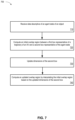
- FIG. 7 depicts a flow diagram of an example method 700 of using a box-shaped probabilistic overlap module to control a trajectory of an AV in accordance with some implementations of the present disclosure.
- the method 700 described below and/or each of its individual functions, routines, subroutines, or operations can be performed by a processing device, having one or more processing units (CPU) and memory devices communicatively coupled to the CPU(s).
- the processing device executing the method 700 can perform instructions from various components of the environment monitoring and prediction component 136 , e.g., the probabilistic overlap module 137 .
- the method 700 can be performed by a single processing thread.
- the method 700 can be performed by two or more processing threads, each thread executing one or more individual functions, routines, subroutines, or operations of the method 700 .
- the processing threads implementing the method 700 can be synchronized (e.g., using semaphores, critical sections, and/or other thread synchronization mechanisms).
- the processing threads implementing the method 700 can be executed asynchronously with respect to each other.
- Various operations of the method 700 can be performed in a different order compared with the order shown in FIG. 7 . Some operations of the method can be performed concurrently with other operations. Some operations can be optional.
- the method 700 begins at block 710 , where a data processing system of an AV (e.g., the data processing system 130 ) receives data descriptive of an agent state of an object (e.g., the agent state 510 ), which may be one of many agent states that model a trajectory of the object.
- the data descriptive of the agent state comprises data descriptive of a position and an orientation (e.g., heading 514 ) of the agent state.
- the data descriptive of the agent state further comprises a speed of the agent state, which may correlate with an uncertainty in the object's position.
- the data descriptive of the agent state corresponds to a particular frame at which the object is observed, and may be generated by an environment monitoring and prediction component (e.g., the environment monitoring and prediction component 136 ).
- the data processing system further receives data descriptive of a path of the AV, from which a trajectory of the AV can be modeled by a plurality of boxes to approximate swept volume of the path (e.g., the AV trajectory 500 ).
- the data descriptive of the path of the AV can include physical dimensions of the AV as well as position and orientation data of the AV along the path.
- the data processing system computes an initial overlap region between a first box representative of the trajectory of the AV (e.g., the box 600 ) and a second box representative of the agent state (e.g., the box 610 ).
- the initial overlap region e.g., the overlap 620
- the lateral dimensions of the second box are representative of uncertainty in a lateral position of the object.
- the lateral dimensions of the second box are selected to result in a parallelogram shape for the initial overlap region.
- an area of the parallelogram is representative of maximum cumulative uncertainty in the lateral position of the agent state.
- the dimensions of the parallelogram may be computed, for example, based on the lateral bounds A in and A out of the AV (e.g., box 600 ) and on the lateral bounds B in and B out of the agent state (e.g., box 610 ), as illustrated and described with respect to FIGS. 6 A- 6 D .
- the data processing system updates dimensions of the second box (e.g., the lateral bounds B in and/or B out of the box 610 ).
- the data processing system updates the dimensions of the second box by increasing or reducing lateral dimensions of the second box (e.g., reducing B in to B′ in and/or B out to B′ out ).
- the dimensions of the second box are updated responsive to the data processing system receiving a query from an AV control system (e.g., the AVCS 140 ).
- the query can indicate a level of risk tolerance with respect to the agent state.
- the level of risk tolerance may be represented as a standard deviation of a Gaussian distribution, with one or more of the lateral bounds of the agent state being shifted to a particular lateral location corresponding to the standard deviation.
- the query may specify a single lateral bound to update, for example, if the AV control system seeks to determine whether maneuvering the AV in a particular direction with respect to the object is feasible. In such implementations, the AV control system may cause the AV to maneuver in that direction if a lateral uncertainty is reduced as a result.
- a change in one or more of the lateral bounds of the agent state can range from 0.1 meters to about 2 meters.
- the data processing system computes an updated overlap region by interpolating the initial overlap region based on the updated dimensions of the second box.
- the data processing system interpolates the initial overlap region by rescaling the initial overlap region using the reduced lateral dimensions of the second box to update the overlap region.
- the interpolation may be performed as described with respect to FIGS. 6 C and 6 D , for which A′ in and A′ out are algebraically computed and used to compute or estimate the overlap region.
- the data processing system transmits to, for example, the AV control system data representative of uncertainty in a lateral position of the object computed based on a relationship between the updated overlap region and the initial overlap region.
- the AV control system is to modify the driving path or speed of the AV based on the data representative of the uncertainty in the lateral position.
- the relationship between the updated overlap region and the initial overlap region is a ratio of an area of the updated overlap region to an area of the original overlap region so as to normalize the area of the updated overlap region.
- method 700 can continue with an AV control system (e.g., the AVCS 140 ) causing a driving path or speed of the AV to be determined in view of the identified objects and one or more computed probabilistic overlaps.
- the perception system could have identified an object moving with the speed of 20 mph while making a left-hand turn with the radius of 15 m and communicated this information to the AV control system.
- the AV control system can then determine, based at least partially on lateral uncertainty of the object's position, that the AV is about to enter the same intersection before the object can complete the turn.
- the AV control system can determine a new path and/or speed for the AV, which can include braking, changing lanes, stopping, backing up, and so on.
- the control system can subsequently output instructions to powertrain and steering 150 , vehicle electronics 160 , signaling 170 , etc., to ensure that the AV follows the determined driving path.
- the computed probabilistic overlaps may be utilized to compute a risk associated with one or more paths to be taken by the AV, which may result in the selection of a path corresponding to the lowest risk.
- FIG. 8 illustrates an exemplary polygon 800 in accordance with some implementations of the present disclosure.
- the polygon 800 is representative of an agent state of an object.
- the polygon 800 may also correspond to an initial overlap region between a first polygon representative of the trajectory of the AV and a second box representative of an agent state.
- the polygon 800 is defined by vertices 803 A- 803 E, though it is to be understood that more or less vertices may be present.
- the polygon 800 is depicted as an irregularly-shaped convex polygon for illustrative purposes. In some implementations, the polygon 800 may be a concave polygon.
- a position 804 of the polygon 800 may correspond to an estimated center of mass of an agent state. In some implementations, the position 804 corresponds to a geometric center of the polygon 800 . In some implementations, a direction of motion of the agent state may be represented as a heading 806 . In some implementations, the heading 806 may coincide with a central longitudinal axis of a bounding box of the polygon 800 (as illustrated).
- Longitudinal axis 808 and lateral axis 810 are illustrated as orthogonal axes, with the longitudinal axis 808 being aligned with the heading 806 , though the longitudinal axis 808 need not be aligned with the heading 806 .
- any axis may be utilized as a search direction for the purpose of identifying extreme vertices of the polygon 802 along that direction.
- the extreme vertices are identified along the longitudinal axis 808 and the lateral axis 810 when the longitudinal axis 808 is aligned with the heading 806 .
- the vertices 803 A and 803 C will be identified as extreme vertices along the longitudinal axis 808 (with the vertex 803 A being an extreme vertex in the heading or front direction, and the vertex 803 C being an extreme vertex in the rear direction).
- the vertices 803 B, 803 D, and 803 E will not be identified as extreme vertices along the longitudinal axis 808 due to the vertices 803 A and 803 C having the greater distances from the lateral axis 810 .
- the vertices 803 B and 803 D will be identified as extreme vertices along the lateral axis 810 (with the vertex 803 B being an extreme vertex in the right direction, and the vertex 803 D being an extreme vertex in the left direction).
- FIG. 9 A illustrates a front portion 902 and a rear portion 904 of the polygon 800 to which an expansion transformation is to be applied in accordance with some implementations of the present disclosure.
- the front portion 902 represented by edges with solid lines
- the rear portion 904 represented by edges with dotted lines
- the extreme vertices 803 B and 803 D represent the points at which the front portion 902 and the rear portion 904 are connected.
- an expansion transformation along the longitudinal axis 808 is applied to the polygon 800 at the lateral extreme vertices 803 B and 803 D, as discussed in FIG. 9 B .
- FIG. 9 B illustrates applying an expansion transformation to the polygon 800 along the longitudinal axis 808 in accordance with some implementations of the present disclosure.
- the transformation along the longitudinal axis 808 results in a transformed polygon 900 .
- the transformation produces a front shift for vertices 803 A and 803 E, and a rear shift for vertex 803 C.
- the transformation further results in the generate of duplicate vertices 903 B and 903 D, which are duplicates of vertices 803 B and 803 D, respectively, with the vertices 803 B and 803 D being displaced by the front shift, and the vertices 903 B and 903 D being displaced by the rear shift.
- the vertices 803 B and 903 B define a new edge 912
- the vertices 803 D and 903 D define a new edge 910
- each of edges 910 and 912 having a length equal to the total distance of the front shift and the rear shift.
- the labeling of the vertices 803 B and 803 D and their respective duplicate vertices 903 B and 903 D is arbitrary, as each original vertex may be swapped with its duplicate.
- the front and rear shift displacements are arbitrary and serve to stretch/extrude the polygon 800 in a manner that preserves angular information at the extreme vertices for any future expansion transformations.
- the vertices along the edge of the polygon 800 are not duplicated depending on the orientation of the direction of the expansion transformation with respect to an edge of the polygon 800 .
- the vertices along the edge are not duplicated, as no additional vertices are needed to preserve the angles between edges during transformations.
- no lateral extreme vertices are duplicated by the expansion transformation (i.e., lateral extreme vertices on both sides of the polygon 800 define edges that are parallel to each other and the direction of the expansion transformation).
- only one lateral extreme vertex is duplicated (e.g., when only one of the lateral extreme vertices of the polygon 800 define an edge that is parallel to the direction of the expansion transformation).
- a right portion 924 (represented by edges with solid lines) and the left portion 922 (represented by edges with dotted lines) are identified based on the extreme vertices identified along the longitudinal axis 808 (i.e., vertices 803 A and 803 C).
- the extreme vertices 803 A and 803 C represent the points at which the right portion 924 and the left portion 922 are connected.
- an expansion transformation along the longitudinal axis 808 is applied to the transformed polygon 800 at the longitudinal extreme vertices 803 A and 803 C, as discussed in FIG. 9 C .
- FIG. 9 C illustrates applying a further expansion transformation to the transformed polygon 900 along the lateral axis 810 to generate a precomputed polygon 950 in accordance with some implementations of the present disclosure.
- the transformation produces a right shift for vertices 803 A, 803 B, 903 B, and 803 C, and a left shift for vertices 803 E, 803 D, and 903 D.
- the transformation further results in the generate of duplicate vertices 903 A and 903 C, which are duplicates of vertices 803 A and 803 C, respectively, with the vertices 803 A and 803 C being displaced by the right shift, and the vertices 903 A and 903 C being displaced by the left shift.
- the vertices 803 A and 903 A define a new edge 934
- the vertices 803 C and 903 C define a new edge 932 , with each of edges 932 and 934 having a length equal to the total distance of the right shift and the left shift.
- the labeling of the vertices 803 A and 803 C and their respective duplicate vertices 903 C and 903 C is arbitrary, as each original vertex may be swapped with its duplicate.
- the right and left shift displacements are arbitrary and serve to stretch/extrude the transformed polygon 900 in a manner that preserves angular information at the extreme vertices for any future expansion transformations. Similar to the discussion above with respect to FIG.
- extreme vertices are not duplicated when such vertices define an edge of the polygon 900 that is parallel to the direction of the expansion transformation.
- no longitudinal extreme vertices are duplicated by the expansion transformation (i.e., lateral extreme vertices on both sides of the polygon 900 define edges that are parallel to each other and the direction of the expansion transformation).
- only one longitudinal extreme vertex is duplicated (e.g., when only one of the longitudinal extreme vertices of the polygon 900 define an edge that is parallel to the direction of the expansion transformation).
- the precomputed polygon 950 can be scaled along longitudinal axis 808 and/or its lateral axis 810 to model an agent state or a probabilistic overlap, with the scaling factors being based on a longitudinal or lateral uncertainty.
- Such transformations applied after the generation of the precomputed polygon 950 will preserve the number of vertices of the precomputed polygon 950 . If the precomputed polygon 950 is rotated, angular information associated with the vertices is preserved, allowing new extreme vertices to be identified if needed.
- the expansion transformation along the lateral axis 810 is performed before the expansion transformation along the longitudinal axis 808 .
- FIG. 10 depicts a flow diagram of an example method 1000 of generating a precomputed polygon for modeling positional uncertainty in a moving object in accordance with some implementations of the present disclosure.
- the method 1000 described below and/or each of its individual functions, routines, subroutines, or operations can be performed by a processing device, having one or more processing units (CPU) and memory devices communicatively coupled to the CPU(s).
- the processing device executing the method 1000 can perform instructions from various components of the environment monitoring and prediction component 136 , e.g., the probabilistic overlap module 137 .
- the method 1000 can be performed by a single processing thread.
- the method 1000 can be performed by two or more processing threads, each thread executing one or more individual functions, routines, subroutines, or operations of the method 1000 .
- the processing threads implementing the method 1000 can be synchronized (e.g., using semaphores, critical sections, and/or other thread synchronization mechanisms).
- the processing threads implementing the method 700 can be executed asynchronously with respect to each other.
- Various operations of the method 1000 can be performed in a different order compared with the order shown in FIG. 10 . Some operations of the method can be performed concurrently with other operations. Some operations can be optional.
- the method 1000 may be performed in combination with the method 700 , for example, to compute the second box representative of the agent state in block 720 and/or to update the dimensions of the second box in block 730 . In at least one implementation, the method 1000 may be performed in combination with the method 700 , for example, to compute the initial overlap region in block 720 .
- the method 1000 begins at block 1010 , where a data processing system (e.g., the data processing system 130 of the AV 100 ) receives data descriptive of an agent state of an object (e.g., the agent state 510 ), which may be one of many agent states that model a trajectory of the object.
- the data processing system receives data descriptive of a probabilistic overlap between the agent state and a trajectory of an AV (e.g., the overlap 620 ).
- the data descriptive of the agent state or the probabilistic overlap comprises data descriptive of a position and an orientation (e.g., heading 514 or heading 806 ) of the agent state.
- the data descriptive of the agent state further comprises a speed of the agent state, which may correlate with an uncertainty in the object's position.
- the data descriptive of the agent state corresponds to a particular frame at which the object is observed, and may be generated by an environment monitoring and prediction component (e.g., the environment monitoring and prediction component 136 ).
- the data processing system generates a polygon representative of the agent state or the probabilistic overlap (e.g., the polygon 800 ).
- the bounds of the polygon are representative of uncertainty in a position of an object along a longitudinal axis (e.g., a direction of motion) and a lateral axis.
- the polygon is a convex polygon defined by 3, 4, 5, or more vertices (e.g., vertices 803 A- 803 E).
- the polygon is box-shaped (e.g., box 610 ).
- the as-generated polygon is not used in downstream data processing. Instead, one or more initial transformations are applied to the polygon to generate a precomputed polygon, which is used in downstream data processing.
- the data processing system identifies extreme vertices of the polygon along a longitudinal axis parallel to a heading direction of the object (e.g., the longitudinal axis 808 parallel to the heading 806 of the polygon 800 ) or a lateral axis orthogonal to the heading direction (e.g., the lateral axis 810 of the polygon 800 ).
- the extreme vertices are identified along both the longitudinal axis and the lateral axis.
- the data processing system applies, based on the extreme vertices, at least one expansion transformation to the polygon along the longitudinal axis (e.g., as illustrated in FIG. 9 B ) or the lateral axis (e.g., as illustrated in FIG. 9 C ) to generate a precomputed polygon (e.g., the precomputed polygon 950 ).
- a driving path or a speed of the AV is modified based on the precomputed polygon.
- applying the at least one expansion transformation comprises applying a first expansion transformation to the polygon along the longitudinal axis to duplicate each lateral extreme vertex (e.g., the vertices 803 D and 903 D, and the vertices 803 B and 903 B), and a second expansion transformation to the polygon along the lateral axis to duplicate each longitudinal extreme vertex (e.g., the vertices 803 A and 903 A, and the vertices 803 C and 903 C).
- the expansion transformation along the lateral axis is applied to the polygon prior to the expansion transformation along the longitudinal axis.
- the data processing system applies at least one additional expansion transformation to the precomputed polygon based on an uncertainty of the agent state.
- a total number of vertices of the precomputed polygon is unchanged by the additional expansion transformation.
- the at least one additional expansion transformation is applied responsive to the data processing system receiving a query from a control system of the AV (e.g., the AVCS 140 ).
- the query can indicate a level of risk tolerance with respect to the agent state.
- the level of risk tolerance for example, may be represented as a standard deviation of a Gaussian distribution, with one or more of the lateral bounds of the agent state being shifted to a particular lateral location corresponding to the standard deviation.
- the query may specify a single lateral bound to update, for example, if the AV control system seeks to determine whether maneuvering the AV in a particular direction with respect to the object is feasible. In such implementations, the AV control system may cause the AV to maneuver in that direction if a lateral uncertainty is reduced as a result. In some implementations, a change in one or more of the lateral bounds of the agent state can range from 0.1 meters to about 2 meters.
- the data processing system transmits, to the control system, data representative of uncertainty in a longitudinal position and a lateral position of the object computed based on the precomputed polygon.
- the control system is to modify the driving path or the speed of the AV based on the data representative of uncertainty in the longitudinal position and the lateral position.
- the data processing system computes a trajectory of the object comprising a series of agent states that includes the agent state of the object.
- the precomputed polygon is used to model each agent state in the series of agent states.
- FIG. 11 depicts a block diagram of an example computer device 1100 capable of enabling Doppler-assisted object identification, tracking, and prediction for autonomous driving vehicle applications.
- Example computer device 1100 can be connected to other computer devices in a LAN, an intranet, an extranet, and/or the Internet.
- Computer device 1100 can operate in the capacity of a server in a client-server network environment.
- Computer device 1100 can be a personal computer (PC), a set-top box (STB), a server, a network router, switch or bridge, or any device capable of executing a set of instructions (sequential or otherwise) that specify actions to be taken by that device.
- PC personal computer
- STB set-top box
- server a server
- network router switch or bridge
- Example computer device 1100 can include a processing device 1102 (also referred to as a processor or CPU), a main memory 1104 (e.g., read-only memory (ROM), flash memory, dynamic random access memory (DRAM) such as synchronous DRAM (SDRAM), etc.), a static memory 1106 (e.g., flash memory, static random access memory (SRAM), etc.), and a secondary memory (e.g., a data storage device 1118 ), which can communicate with each other via a bus 1130 .
- a processing device 1102 also referred to as a processor or CPU
- main memory 1104 e.g., read-only memory (ROM), flash memory, dynamic random access memory (DRAM) such as synchronous DRAM (SDRAM), etc.
- DRAM dynamic random access memory
- SDRAM synchronous DRAM
- static memory e.g., flash memory, static random access memory (SRAM), etc.
- secondary memory e.g., a data storage device 1118
- Processing device 1102 represents one or more general-purpose processing devices such as a microprocessor, central processing unit, or the like. More particularly, processing device 1102 can be a complex instruction set computing (CISC) microprocessor, reduced instruction set computing (RISC) microprocessor, very long instruction word (VLIW) microprocessor, processor implementing other instruction sets, or processors implementing a combination of instruction sets. Processing device 1102 can also be one or more special-purpose processing devices such as an application specific integrated circuit (ASIC), a field programmable gate array (FPGA), a digital signal processor (DSP), network processor, or the like. In accordance with one or more aspects of the present disclosure, processing device 1102 can be configured to execute instructions performing the methods 700 or 1000 as described above.
- ASIC application specific integrated circuit
- FPGA field programmable gate array
- DSP digital signal processor
- Example computer device 1100 can further comprise a network interface device 1108 , which can be communicatively coupled to a network 1120 .
- Example computer device 1100 can further comprise a video display 1110 (e.g., a liquid crystal display (LCD), a touch screen, or a cathode ray tube (CRT)), an alphanumeric input device 1112 (e.g., a keyboard), a cursor control device 1114 (e.g., a mouse), and an acoustic signal generation device 1116 (e.g., a speaker).
- a video display 1110 e.g., a liquid crystal display (LCD), a touch screen, or a cathode ray tube (CRT)
- an alphanumeric input device 1112 e.g., a keyboard
- a cursor control device 1114 e.g., a mouse
- an acoustic signal generation device 1116 e.g., a speaker
- Data storage device 1118 can include a computer-readable storage medium (or, more specifically, a non-transitory computer-readable storage medium) 1128 on which is stored one or more sets of executable instructions 1122 .
- executable instructions 1122 can comprise executable instructions for performing the methods 700 or 1000 as described above.
- Executable instructions 1122 can also reside, completely or at least partially, within main memory 1104 and/or within processing device 1102 during execution thereof by example computer device 1100 , main memory 1104 and processing device 1102 also constituting computer-readable storage media. Executable instructions 1122 can further be transmitted or received over a network via network interface device 1108 .
- While the computer-readable storage medium 1128 is shown in FIG. 11 as a single medium, the term “computer-readable storage medium” should be taken to include a single medium or multiple media (e.g., a centralized or distributed database, and/or associated caches and servers) that store the one or more sets of operating instructions.
- the term “computer-readable storage medium” shall also be taken to include any medium that is capable of storing or encoding a set of instructions for execution by the machine that cause the machine to perform any one or more of the methods described herein.
- the term “computer-readable storage medium” shall accordingly be taken to include, but not be limited to, solid-state memories, and optical and magnetic media.
- Examples of the present disclosure also relate to an apparatus for performing the methods described herein.
- This apparatus can be specially constructed for the required purposes, or it can be a general purpose computer system selectively programmed by a computer program stored in the computer system.
- a computer program can be stored in a computer readable storage medium, such as, but not limited to, any type of disk including optical disks, CD-ROMs, and magnetic-optical disks, read-only memories (ROMs), random access memories (RAMs), EPROMs, EEPROMs, magnetic disk storage media, optical storage media, flash memory devices, other type of machine-accessible storage media, or any type of media suitable for storing electronic instructions, each coupled to a computer system bus.
Abstract
Description
{right arrow over (V)}={right arrow over (V)} O+{right arrow over (Ω)}×({right arrow over (R)}−{right arrow over (R)} O′),
where {right arrow over (R)}O is the radius vector of some reference point. The reference point can be any element of the object, e.g. an element associated with the return point (3) or any other return point. The choice of the reference point O can be arbitrary since the same rigid body equation exists for any other reference point O′, as
{right arrow over (V)}={right arrow over (V)} O+{right arrow over (Ω)}×({right arrow over (R)}−{right arrow over (R)} O′ −{right arrow over (R)} O +{right arrow over (R)} O′)
={right arrow over (V)} O′+{right arrow over (Ω)}×({right arrow over (R)}−{right arrow over (R)} O′),
where {right arrow over (V)}O={right arrow over (V)}O+{right arrow over (Ω)}×({right arrow over (R)}O′−{right arrow over (R)}O) is the linear velocity of the other reference point O′. Although the linear velocity changes when the reference point is changed, the angular velocity is independent of the choice of the reference point. This independence provides additional flexibility by enabling to choose the reference point based on convenience (e.g., near the center of the cluster of points detected by the sensing system 120).
A′ in =A in+Δin·sin θ, and
A′ out =A out−Δout·sin θ.
Claims (18)
Priority Applications (1)
| Application Number | Priority Date | Filing Date | Title |
|---|---|---|---|
| US17/354,614 US11753045B2 (en) | 2021-06-22 | 2021-06-22 | Modeling positional uncertainty of moving objects using precomputed polygons |
Applications Claiming Priority (1)
| Application Number | Priority Date | Filing Date | Title |
|---|---|---|---|
| US17/354,614 US11753045B2 (en) | 2021-06-22 | 2021-06-22 | Modeling positional uncertainty of moving objects using precomputed polygons |
Publications (2)
| Publication Number | Publication Date |
|---|---|
| US20220402527A1 US20220402527A1 (en) | 2022-12-22 |
| US11753045B2 true US11753045B2 (en) | 2023-09-12 |
Family
ID=84491053
Family Applications (1)
| Application Number | Title | Priority Date | Filing Date |
|---|---|---|---|
| US17/354,614 Active 2041-11-12 US11753045B2 (en) | 2021-06-22 | 2021-06-22 | Modeling positional uncertainty of moving objects using precomputed polygons |
Country Status (1)
| Country | Link |
|---|---|
| US (1) | US11753045B2 (en) |
Families Citing this family (1)
| Publication number | Priority date | Publication date | Assignee | Title |
|---|---|---|---|---|
| US20230192147A1 (en) * | 2021-12-22 | 2023-06-22 | Gm Cruise Holdings Llc | Using maps at multiple resolutions and scale for trajectory prediction |
Citations (12)
| Publication number | Priority date | Publication date | Assignee | Title |
|---|---|---|---|---|
| US20190146498A1 (en) * | 2017-02-16 | 2019-05-16 | Faraday&Future Inc. | Methods and systems for vehicle motion planning |
| CN111830979A (en) * | 2020-07-13 | 2020-10-27 | 广州小鹏车联网科技有限公司 | Trajectory optimization method and device |
| US20210041887A1 (en) * | 2019-08-06 | 2021-02-11 | Boston Dynamics, Inc. | Constrained Mobility Mapping |
| US20210046954A1 (en) * | 2019-08-16 | 2021-02-18 | Uatc, Llc | Full Uncertainty for Motion Planning in Autonomous Vehicles |
| US20210078173A1 (en) * | 2017-03-27 | 2021-03-18 | Ping An Technology (Shenzhen) Co., Ltd. | System and method of controlling obstacle avoidance of robot, robot and storage medium |
| US20210284198A1 (en) * | 2020-03-10 | 2021-09-16 | Seegrid Corporation | Self-driving vehicle path adaptation system and method |
| US20210294333A1 (en) * | 2020-03-20 | 2021-09-23 | Tusimple, Inc. | Optimal path library for local path planning of an autonomous vehicle |
| US20210370921A1 (en) * | 2020-05-27 | 2021-12-02 | Zoox, Inc. | Vehicle collision avoidance based on perturbed object trajectories |
| US20210406560A1 (en) * | 2020-06-25 | 2021-12-30 | Nvidia Corporation | Sensor fusion for autonomous machine applications using machine learning |
| US20220135029A1 (en) * | 2020-11-05 | 2022-05-05 | Zoox, Inc. | Allocation of safety system resources based on probability of intersection |
| US20220161822A1 (en) * | 2020-11-25 | 2022-05-26 | Zoox, Inc. | Object uncertainty models |
| US20220185266A1 (en) * | 2020-12-10 | 2022-06-16 | Zoox, Inc. | Velocity-based relevance filter |
-
2021
- 2021-06-22 US US17/354,614 patent/US11753045B2/en active Active
Patent Citations (12)
| Publication number | Priority date | Publication date | Assignee | Title |
|---|---|---|---|---|
| US20190146498A1 (en) * | 2017-02-16 | 2019-05-16 | Faraday&Future Inc. | Methods and systems for vehicle motion planning |
| US20210078173A1 (en) * | 2017-03-27 | 2021-03-18 | Ping An Technology (Shenzhen) Co., Ltd. | System and method of controlling obstacle avoidance of robot, robot and storage medium |
| US20210041887A1 (en) * | 2019-08-06 | 2021-02-11 | Boston Dynamics, Inc. | Constrained Mobility Mapping |
| US20210046954A1 (en) * | 2019-08-16 | 2021-02-18 | Uatc, Llc | Full Uncertainty for Motion Planning in Autonomous Vehicles |
| US20210284198A1 (en) * | 2020-03-10 | 2021-09-16 | Seegrid Corporation | Self-driving vehicle path adaptation system and method |
| US20210294333A1 (en) * | 2020-03-20 | 2021-09-23 | Tusimple, Inc. | Optimal path library for local path planning of an autonomous vehicle |
| US20210370921A1 (en) * | 2020-05-27 | 2021-12-02 | Zoox, Inc. | Vehicle collision avoidance based on perturbed object trajectories |
| US20210406560A1 (en) * | 2020-06-25 | 2021-12-30 | Nvidia Corporation | Sensor fusion for autonomous machine applications using machine learning |
| CN111830979A (en) * | 2020-07-13 | 2020-10-27 | 广州小鹏车联网科技有限公司 | Trajectory optimization method and device |
| US20220135029A1 (en) * | 2020-11-05 | 2022-05-05 | Zoox, Inc. | Allocation of safety system resources based on probability of intersection |
| US20220161822A1 (en) * | 2020-11-25 | 2022-05-26 | Zoox, Inc. | Object uncertainty models |
| US20220185266A1 (en) * | 2020-12-10 | 2022-06-16 | Zoox, Inc. | Velocity-based relevance filter |
Non-Patent Citations (5)
| Title |
|---|
| Hang et al., "Path planning of collision avoidance for unmanned ground vehicles: A nonlinear model predictive control approach", Proc IMechE Part I: J Systems and Control Engineering, 2020 (Year: 2020). * |
| Hodo et al., "Optimal Path Planning with Obstacle Avoidance for Autonomous Surveying", Auburn University, IEEE, 2010 (Year: 2010). * |
| Jacobs et al., "Planning Smooth Paths for Mobile Robots", University of California, 1989 International Conference on Robotics and Automation (Year: 1989). * |
| Lozano-Perez et al., "An Algorithm for Planning Collision-Free Paths Among Polyhedral Obstacles", IBM Thomas J. Watson Research Center, vol. 22, No. 10, Oct. 1979 (Year: 1979). * |
| Sedighi et al., "Fusing Direct Visibility Diagram with Clothoid Curves for Motion Planning", 2019 IEEE Intelligent Transportation Systems Conference (ITSC), Auckland, NZ, Oct. 27-30, 2019 (Year: 2019). * |
Also Published As
| Publication number | Publication date |
|---|---|
| US20220402527A1 (en) | 2022-12-22 |
Similar Documents
| Publication | Publication Date | Title |
|---|---|---|
| US20220146676A1 (en) | Doppler-assisted object mapping for autonomous vehicle applications | |
| US11702102B2 (en) | Filtering return points in a point cloud based on radial velocity measurement | |
| US11841439B2 (en) | Point cloud segmentation using a coherent lidar for autonomous vehicle applications | |
| US20220128995A1 (en) | Velocity estimation and object tracking for autonomous vehicle applications | |
| US20220169254A1 (en) | Systems and techniques for field-of-view improvements in autonomous trucking systems | |
| US20220402521A1 (en) | Autonomous path generation with path optimization | |
| US20230260266A1 (en) | Camera-radar data fusion for efficient object detection | |
| Moras et al. | Drivable space characterization using automotive lidar and georeferenced map information | |
| US20230038842A1 (en) | Association of camera images and radar data in autonomous vehicle applications | |
| US20230384441A1 (en) | Estimating three-dimensional target heading using a single snapshot | |
| CN115508851A (en) | Determination of atmospheric visibility in autonomous vehicle applications | |
| US11753045B2 (en) | Modeling positional uncertainty of moving objects using precomputed polygons | |
| US20220194424A1 (en) | Autonomous vehicle trajectory computed using box-based probabilistic overlap model | |
| US20230384442A1 (en) | Estimating target heading using a single snapshot | |
| US20230294687A1 (en) | End-to-end processing in automated driving systems | |
| EP4180835A1 (en) | Calibration of sensors in autonomous vehicle applications | |
| EP4170606A1 (en) | Identification of real and image sign detections in driving applications | |
| WO2023158642A1 (en) | Camera-radar data fusion for efficient object detection | |
| US11656629B1 (en) | Detection of particulate matter in autonomous vehicle applications | |
| US20220135074A1 (en) | Classification of objects based on motion patterns for autonomous vehicle applications | |
| US20240025446A1 (en) | Motion planning constraints for autonomous vehicles | |
| US20240134054A1 (en) | Point cloud segmentation using a coherent lidar for autonomous vehicle applications | |
| US20220402520A1 (en) | Implementing synthetic scenes for autonomous vehicles | |
| US20230082264A1 (en) | Flow-based motion planning blueprint for autonomous vehicles | |
| US11904886B1 (en) | Modifying autonomous vehicle behavior prediction based on behavior prediction errors |
Legal Events
| Date | Code | Title | Description |
|---|---|---|---|
| FEPP | Fee payment procedure |
Free format text: ENTITY STATUS SET TO UNDISCOUNTED (ORIGINAL EVENT CODE: BIG.); ENTITY STATUS OF PATENT OWNER: LARGE ENTITY |
|
| STPP | Information on status: patent application and granting procedure in general |
Free format text: DOCKETED NEW CASE - READY FOR EXAMINATION |
|
| AS | Assignment |
Owner name: WAYMO LLC, CALIFORNIA Free format text: ASSIGNMENT OF ASSIGNORS INTEREST;ASSIGNORS:LI, DONG;PUCHKAREV, VICTOR;SIGNING DATES FROM 20220129 TO 20220202;REEL/FRAME:058867/0464 |
|
| STPP | Information on status: patent application and granting procedure in general |
Free format text: NOTICE OF ALLOWANCE MAILED -- APPLICATION RECEIVED IN OFFICE OF PUBLICATIONS |
|
| STPP | Information on status: patent application and granting procedure in general |
Free format text: PUBLICATIONS -- ISSUE FEE PAYMENT VERIFIED |
|
| STCF | Information on status: patent grant |
Free format text: PATENTED CASE |