US11752275B2 - RFID tag enabled shield assembly - Google Patents
RFID tag enabled shield assembly Download PDFInfo
- Publication number
- US11752275B2 US11752275B2 US16/361,576 US201916361576A US11752275B2 US 11752275 B2 US11752275 B2 US 11752275B2 US 201916361576 A US201916361576 A US 201916361576A US 11752275 B2 US11752275 B2 US 11752275B2
- Authority
- US
- United States
- Prior art keywords
- shield assembly
- rfid tag
- medicament
- flexible component
- assembly
- Prior art date
- Legal status (The legal status is an assumption and is not a legal conclusion. Google has not performed a legal analysis and makes no representation as to the accuracy of the status listed.)
- Active, expires
Links
- 239000003814 drug Substances 0.000 claims abstract description 110
- 238000002347 injection Methods 0.000 claims abstract description 60
- 239000007924 injection Substances 0.000 claims abstract description 60
- 238000011049 filling Methods 0.000 claims description 12
- 239000007788 liquid Substances 0.000 claims description 8
- 238000004891 communication Methods 0.000 claims description 7
- 239000000853 adhesive Substances 0.000 claims description 6
- 230000001070 adhesive effect Effects 0.000 claims description 6
- 238000003908 quality control method Methods 0.000 claims description 6
- 238000007789 sealing Methods 0.000 claims description 6
- 238000012360 testing method Methods 0.000 claims description 4
- 230000002427 irreversible effect Effects 0.000 claims description 3
- 238000003475 lamination Methods 0.000 claims description 2
- 230000002441 reversible effect Effects 0.000 claims 1
- 238000000034 method Methods 0.000 abstract description 18
- 229940071643 prefilled syringe Drugs 0.000 abstract description 12
- 238000013037 co-molding Methods 0.000 abstract description 8
- 238000009826 distribution Methods 0.000 abstract description 6
- 238000004806 packaging method and process Methods 0.000 abstract description 3
- 238000004519 manufacturing process Methods 0.000 description 37
- 210000002105 tongue Anatomy 0.000 description 18
- 230000007246 mechanism Effects 0.000 description 14
- 239000000463 material Substances 0.000 description 13
- 230000008569 process Effects 0.000 description 12
- 239000012190 activator Substances 0.000 description 10
- 230000000712 assembly Effects 0.000 description 8
- 238000000429 assembly Methods 0.000 description 8
- 230000006835 compression Effects 0.000 description 8
- 238000007906 compression Methods 0.000 description 8
- 238000013461 design Methods 0.000 description 6
- 239000012530 fluid Substances 0.000 description 6
- 238000003860 storage Methods 0.000 description 6
- 229940079593 drug Drugs 0.000 description 5
- 239000004033 plastic Substances 0.000 description 5
- 229920003023 plastic Polymers 0.000 description 5
- 238000012377 drug delivery Methods 0.000 description 4
- 230000008901 benefit Effects 0.000 description 3
- 230000036541 health Effects 0.000 description 3
- 238000010348 incorporation Methods 0.000 description 3
- 238000012546 transfer Methods 0.000 description 3
- 238000004458 analytical method Methods 0.000 description 2
- 229940090047 auto-injector Drugs 0.000 description 2
- 230000006378 damage Effects 0.000 description 2
- 238000005429 filling process Methods 0.000 description 2
- 230000006870 function Effects 0.000 description 2
- 239000011521 glass Substances 0.000 description 2
- 238000001802 infusion Methods 0.000 description 2
- 230000007704 transition Effects 0.000 description 2
- 230000004913 activation Effects 0.000 description 1
- 230000006978 adaptation Effects 0.000 description 1
- 239000003708 ampul Substances 0.000 description 1
- 238000005452 bending Methods 0.000 description 1
- 230000009286 beneficial effect Effects 0.000 description 1
- 239000011248 coating agent Substances 0.000 description 1
- 238000000576 coating method Methods 0.000 description 1
- 238000005336 cracking Methods 0.000 description 1
- 238000013480 data collection Methods 0.000 description 1
- 238000005516 engineering process Methods 0.000 description 1
- 238000010304 firing Methods 0.000 description 1
- 230000036512 infertility Effects 0.000 description 1
- 230000000977 initiatory effect Effects 0.000 description 1
- 230000003993 interaction Effects 0.000 description 1
- 230000014759 maintenance of location Effects 0.000 description 1
- 230000013011 mating Effects 0.000 description 1
- 230000005226 mechanical processes and functions Effects 0.000 description 1
- 239000002184 metal Substances 0.000 description 1
- 238000000465 moulding Methods 0.000 description 1
- 230000037368 penetrate the skin Effects 0.000 description 1
- 230000035515 penetration Effects 0.000 description 1
- 238000011084 recovery Methods 0.000 description 1
- 230000003014 reinforcing effect Effects 0.000 description 1
- 239000000243 solution Substances 0.000 description 1
- 239000000126 substance Substances 0.000 description 1
Images


Classifications
-
- A—HUMAN NECESSITIES
- A61—MEDICAL OR VETERINARY SCIENCE; HYGIENE
- A61M—DEVICES FOR INTRODUCING MEDIA INTO, OR ONTO, THE BODY; DEVICES FOR TRANSDUCING BODY MEDIA OR FOR TAKING MEDIA FROM THE BODY; DEVICES FOR PRODUCING OR ENDING SLEEP OR STUPOR
- A61M5/00—Devices for bringing media into the body in a subcutaneous, intra-vascular or intramuscular way; Accessories therefor, e.g. filling or cleaning devices, arm-rests
- A61M5/178—Syringes
- A61M5/31—Details
- A61M5/32—Needles; Details of needles pertaining to their connection with syringe or hub; Accessories for bringing the needle into, or holding the needle on, the body; Devices for protection of needles
- A61M5/3202—Devices for protection of the needle before use, e.g. caps
-
- A—HUMAN NECESSITIES
- A61—MEDICAL OR VETERINARY SCIENCE; HYGIENE
- A61M—DEVICES FOR INTRODUCING MEDIA INTO, OR ONTO, THE BODY; DEVICES FOR TRANSDUCING BODY MEDIA OR FOR TAKING MEDIA FROM THE BODY; DEVICES FOR PRODUCING OR ENDING SLEEP OR STUPOR
- A61M5/00—Devices for bringing media into the body in a subcutaneous, intra-vascular or intramuscular way; Accessories therefor, e.g. filling or cleaning devices, arm-rests
- A61M5/178—Syringes
- A61M5/31—Details
- A61M5/32—Needles; Details of needles pertaining to their connection with syringe or hub; Accessories for bringing the needle into, or holding the needle on, the body; Devices for protection of needles
- A61M5/3205—Apparatus for removing or disposing of used needles or syringes, e.g. containers; Means for protection against accidental injuries from used needles
- A61M5/321—Means for protection against accidental injuries by used needles
- A61M5/3213—Caps placed axially onto the needle, e.g. equipped with finger protection guards
-
- A—HUMAN NECESSITIES
- A61—MEDICAL OR VETERINARY SCIENCE; HYGIENE
- A61M—DEVICES FOR INTRODUCING MEDIA INTO, OR ONTO, THE BODY; DEVICES FOR TRANSDUCING BODY MEDIA OR FOR TAKING MEDIA FROM THE BODY; DEVICES FOR PRODUCING OR ENDING SLEEP OR STUPOR
- A61M2205/00—General characteristics of the apparatus
- A61M2205/60—General characteristics of the apparatus with identification means
- A61M2205/6054—Magnetic identification systems
Definitions
- the present invention relates to the use of RFID tags in medical devices, more specifically an RFID tag incorporated into or attached to a needle shield assembly of an injection device.
- RFID tag enabled needle shield can be useful in tracking the product life cycle, including the manufacturing, assembly, and distribution histories of an injection device designed to deliver one or more doses of a medicament.
- Such a data carrier system should be integral with medical devices, preferably starting with a component of the device that represents the very beginning of the manufacturing or product life cycle.
- RFID tags chips
- the use of RFID tags should allow data writing and data reading through the entire history of the medical device, including data from the pharmaceutical manufacturer, the fill/finish process, the device assembly steps, the distribution centers, all the way through to the end user, the health care providers and patients.
- Such a tracking system is also useful in device quality control whereby specific physical, mechanical and chemical criteria are met, to ensure proper mechanical function of the device.
- this includes criteria that arise during the syringe manufacturing process as well as during the device manufacturing, filling and packaging/assembly process. Having quality control data written to and read from individual devices will minimize scrap rates thus reducing the loss associated with expensive medicaments that are pre-filled into such devices.
- quality complaints from end users regarding specific components of the device or the entire final device itself sometimes it is not easy, to clearly identify the root cause and have at the same time traceability to identify the relevant products based on additional information that is linked to each product.
- One primary purpose of the present invention is to provide a shield assembly that provides a sterile enclosure of an injection needle or other medicament delivery port that is fixedly attached to a pre-filled syringe or other medicament container configured to hold one or more doses of a medicament, e.g., a drug.
- the shield assembly comprises an interior portion fabricated from a material that forms a sterile and fluid tight seal with a distal end of the injection needle or medicament exit port.
- Fixedly attached to the shield assembly is an RFID tag that is configured as a read-write device that can store data throughout the product life cycle and can be read by an RFID reader as often as needed throughout the product life cycle. In some cases, it may be beneficial that the RFID tag be a read-only having a memory that contains only unique product identification data.
- the shield assembly can further comprise a rigid outer cover and a soft inner cover, where the rigid outer cover is attached to the soft cover such that axial movement of rigid outer cover causes axial movement of the soft inner cover.
- the RFID tag is preferably fixedly attached to the rigid outer cover. This can be achieved by one of a variety of fasteners, for example, a snap fit, an inlay, co-molding, an adhesive, lamination, tape, a press fit or a combination of any of these attachment methods.
- the shield assembly can also have an antenna in electrical communication with the RFID tag.
- the shield assembly can be part of entire complete injection device, where the shield assembly is attached to a medicament container that is incorporated into a completely assembled injection device, such as a pen-type injector, an auto-injector that uses a pre-filled syringe, an infusion pump delivery system, or a patch type device.
- a completely assembled injection device such as a pen-type injector, an auto-injector that uses a pre-filled syringe, an infusion pump delivery system, or a patch type device.
- the injection device can itself have one or more RFID tags associated with one or more components of the device in addition to the RFID tag enabled needle shield assembly. These additional RFID tags can be configured to exchange information with the RFID tag attached to the shield assembly.
- Another aspect of the invention relates to methods of tracking the life cycle of a medicament container or medicament delivery device comprising the RFID tag enabled shield assembly needle (referred to herein also as a needle shield assembly) or tracking the life cycle of the injection device incorporating the needle shield assembly from a point in time where the RFID tag is attached to a needle shield assembly and the assembly is then removably attached an injection needle or medicament delivery port connected to a medicament container, such as a syringe barrel, bag, pouch, vial, cartridge, or other medicament compatible container to form a sterile and fluid tight seal with a distal end of the injection needle.
- a medicament container such as a syringe barrel, bag, pouch, vial, cartridge, or other medicament compatible container to form a sterile and fluid tight seal with a distal end of the injection needle.
- the shield assembly is characterized in that it contains a flexible component that is in fluid communication with the medicament in a container, where this flexible component is made from a material that forms a sterile and fluid tight seal with the container.
- the shield assembly further contains at least one RFID tag.
- the shield assembly can further include a less flexible component, for example, a hub, a covering, a cap, a lid, or other closure material that can also attach directly to the medicament container.
- the RFID tag can be associated with either the flexible or less flexible components, or in some applications both components.
- FIG. 1 is a perspective view of the drug delivery device of one embodiment of the present disclosure
- FIG. 2 is a cross-sectional view of the drug delivery device according to FIG. 1 showing an embodiment of the RFID tag enabled needle shield assembly of the present disclosure
- FIG. 3 is a perspective exploded view of the embodiment of FIG. 1 in a disassembled state
- FIG. 4 is a perspective exploded view of a portion of the device of FIG. 1 ;
- FIG. 5 is a cross-sectional view of a schematic representation of an embodiment of the RFID tag enabled needle shield assembly of the present disclosure
- FIG. 6 is a perspective view of mold core pin that could be used manufacture an embodiment of the RFID tag enabled needle shield assembly of the present disclosure
- FIG. 7 is a cross-sectional view of a schematic representation of an embodiment of the RFID tag enabled needle shield assembly of the present disclosure
- FIG. 8 is a cross-sectional view of a schematic representation of an embodiment of the RFID tag enabled needle shield assembly of the present disclosure
- FIG. 9 is a cross-sectional view of a schematic representation of an embodiment of the RFID tag enabled needle shield assembly of the present disclosure.
- FIG. 10 is a cross-sectional view of a schematic representation of an embodiment of the RFID tag enabled needle shield assembly having an antenna of the present disclosure
- FIG. 11 is a cross-sectional view of a schematic representation of an embodiment of the RFID tag enabled needle shield assembly having an antenna of the present disclosure
- FIG. 12 is a schematic representation of an embodiment of an RFID tag and antenna combination of the present disclosure.
- FIG. 13 is a perspective view of the drug delivery device of FIG. 1 having attached thereto a device accessory;
- FIG. 14 A shows a pre-filled syringe having a tapered proximal end that does not contain a staked needle and has a RFID tag enabled shield assembly of the present disclosure attached via a friction fit;
- FIG. 14 B is a cross-sectional view of the device of FIG. 14 A ;
- FIG. 15 A shows a pre-filled syringe having a tapered proximal end that does not contain a staked needle and has a RFID tag enabled shield assembly of the present disclosure having a threaded hub attached via a friction fit;
- FIG. 15 B is a cross-sectional view of the device of FIG. 15 A ;
- FIG. 16 A shows a pre-filled syringe having a tapered proximal end that does not contain a staked needle and has a RFID tag enabled shield assembly of the present disclosure having a threaded hub attached via a friction fit;
- FIG. 16 B is a cross-sectional view of the device of FIG. 16 A ;
- FIG. 16 C is a partial cross-sectional view of a variation of the device of FIG. 16 A
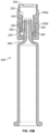
- FIG. 17 shows a syringe having that does not contain a staked needle and has a RFID tag enabled shield assembly of the present disclosure having a threaded hub that is attached to the proximal end of the syringe and a flexible covering configured to seal the proximal end of the syringe;
- FIG. 18 A shows a medicament vial having a RFID tag enabled shield assembly of the present disclosure
- FIG. 18 B is a cross-sectional view of the vial and shield assembly of FIG. 19 A prior to attachment to the vial;
- FIG. 18 c is a perspective view of the underside of the shield assembly of FIG. 19 A ;
- FIG. 19 shows the top side and underside of a RFID tag enabled shield assembly of the present disclosure configured for attachment to and sealing of an IV bag or pouch.
- medicament delivery devices are comprised of a main housing that encloses the mechanism for the setting of one or more doses of medicament and/or for delivering those set doses of medicament contained in a separate container within the main housing or attached to the main housing.
- a shield assembly can be used with a number of medicament delivery devices, one of the most common devices is illustrated in FIG. 1 as one example of an injection device. This particular injection device is an auto-injector.
- the needle shield of the present disclosure is referred to herein as a needle shield assembly.
- the drug delivery device 100 shown in the drawings comprises a front or proximal end 10 and a rear or distal end 61 .
- the front end 10 comprises a generally tubular front body 12 having elongated openings 14 for viewing a syringe 16 as shown in FIGS. 1 and 2 and having a somewhat narrowing front end 12 a (see FIG. 3 ).
- the rear end 61 of device 100 has a rear tubular rear body 13 that is joined with front body 12 with connection 15 (see FIG. 2 ), where one part of the connection 15 is on the front body 12 and the cooperating and mating connector is on the rear body 13 .
- Inside the front body 12 is a needle shield 20 that is axially slidably arranged.
- the needle shield 20 is generally tubular with a first front part 22 having a certain diameter and a second rear part 24 having a diameter larger than the front part 22 , where these parts are joined by an intermediate conical part 26 .
- Two elongated grooves 28 are arranged along the needle shield 20 , on opposite sides of the needle shield 20 , also for viewing the syringe and guiding axial movement of the outer body 57 .
- On the inner surface of the conical part 26 a circumferential ledge 30 is arranged.
- two openings 32 are arranged opposite each other, where each opening 32 is arranged with somewhat inwardly projecting, flexible, tongues 34 .
- a syringe carrier assembly 36 is arranged inside the needle shield 20 and is axially slidable in the proximal direction.
- the syringe carrier assembly 36 as shown in FIGS. 2 - 4 comprises an outer body 57 and an inner body 56 , both of which are preferably tubular in shape, with the inner body 56 fitting within, and being slidable relative to the outer body 57 .
- the syringe 16 is positioned within the inner body 56 such that there is no relative axial movement between the syringe and the inner body 56 .
- Plunger 60 is in contact with the stopper 16 d of the syringe 16 .
- This contact between the plunger 60 and the stopper 16 d prevents the syringe 16 from moving in a distal direction. Also prohibiting movement of the syringe 16 within and relative to the inner body is the pointed tongues 54 that is part of the cap assembly 50 . These tongues grab the needle protection shield 50 b that has attached an RFID tag 202 and assists in holding the syringe 16 in place until cap 50 is removed prior to use of the device. There are no direct attachments or connections between the syringe and the inner body.
- the proximal end 56 c of the inner body 56 is tapered or narrowed to accommodate the proximal end of syringe 16 when it is placed within the inner body 56 .
- the outer body 57 fits over the inner body 56 in a manner that allows relative axial movement between the inner body 56 and the outer body 57 .
- One such force dissipation mechanism includes a dampener ring 58 that is employed as a third component of this syringe carrier assembly 36 .
- the dampener ring 58 is fitted over the outside surface 56 a of the inner body 56 or alternatively fitted into cup portion 57 a at the distal end of outer body 57 and abutting distal facing inner lip 57 b.
- the inner body 56 is also a hollow tube having tapered or narrowing open proximal end 56 c that has an internal shape to accept and hold the proximal end of syringe 16 allowing only the staked needle 16 c and/or needle hub assembly 16 b to protrude proximally from the inner body 56 , see FIG. 2 .
- the distal end of the inner body 56 terminates in a flange configuration that has a diameter greater than the outer diameter of the inner body 56 .
- the flange provides a distal bearing surface for abutment with syringe flange and a proximal bearing surface 56 h for abutment with the distal bearing surface of the dampener ring 58 .
- plunger 60 is in contact with the stopper 16 d of the syringe 16 .
- This contact between the plunger 60 and the stopper 16 d prevents the syringe 16 from moving in a distal direction.
- the pointed tongues 54 that is part of the cap assembly 50 . (see FIG. 4 ). These tongues grab the needle protection shield 50 b and assists in holding the syringe 16 in place until cap 50 is removed prior to use of the device.
- the proximal end 56 c of the inner body 56 is tapered or narrowed to accommodate the proximal end of syringe 16 when it is placed with the inner body.
- the outer body 57 fits over the inner body 56 in a manner that allows relative axial movement between the inner body 56 and the outer body 57 .
- a needle protection shield 50 b Attached to the staked needle hub 16 b that holds needle 16 c of syringe 16 is a needle protection shield 50 b that is friction fitted to the staked needle hub 16 b of the syringe 16 .
- the needle protection shield 50 b is surrounded by needle shield grabber 52 having sharp pointed tongues 54 directed somewhat inwards and towards the front or proximal end of the device.
- the needle shield grabber 52 is operatively connected with cap 50 such that removal of cap 50 results in simultaneous removal of needle protection shield 50 b and grabber 52 .
- the needle shield 50 b is typically added to the stacked needle hub 16 b by the manufacture of the medicament container, typically a syringe manufacture, as part of the pre-filled syringe manufacturing process prior to the medicament container being filled with the medicament.
- the syringe manufacturer will also be responsible for attaching (staking) needle 16 c to hub 16 b and also for forming siliconization of the inside of the syringe.
- the needle shield assembly must be fabricated, as discussed, below in more detail.
- the fabricator of the needle shield assembly of the invention will combine the RFID tag with the material used to form the needle shield.
- the RFID tag is capable of storing data that will allow historical tracking.
- the syringe manufacture will receive the RFID tag enabled needle shield assemblies and needle cannula from another manufacture and will combine these two components as part of the syringe manufacturing process.
- the RFID tag can store information inputted by the syringe manufacturer that relates to the cannula source, such as dates, lot numbers, cannula manufacturer identification, locations, etc.
- the syringe manufacturer can also add data to the RFID relating to siliconization parameters, dates, formulas, testing criteria, etc.
- the syringe with the needle shield assembly is then transferred directly to a medicament filling location or stored/warehoused until shipped to a filling location.
- data can be written to or read from the RFID tag to track and/or record information relating to the product history.
- the medicament filling process is typically performed by another manufacturer, namely a pharmaceutical company or a contract filling company.
- the filling manufacturer can read and write information to the RFID tag relating to medicament, i.e., lot numbers, dates of manufacturing, warnings, safety information, instructions for use, dose limitations, etc.
- the RFID tag By including the RFID tag as part of the needle shield assembly, this allows tracking and data collection very early in the overall manufacturing process of the complete injection device.
- the RFID tag is capable of storing data relating to almost the complete history of injection device.
- Each of the above parties may have different quality and product specific criteria that they control individually and which they document independently from the other parties.
- the injection device assembly process typically joins or marries the pre-filled syringe with the RFID tag enabled needle shield with the various metal or plastic components that form the working parts of injection device, i.e. dose mechanism, and that cause the medicament in the syringe to be forced through the needle 16 c .
- data can be written to and/or read from the RFID tag.
- a second RFID tag may accompany one or more components of the dose mechanism. This second RFID tag would contain historical data relating to the manufacture of these components.
- FIG. 5 illustrates one possible needle shield design that comprises a rigid sheath 203 surrounding and enclosing a flexible needle sheath 201 that is made from a material that is softer than the material used to fabricate the rigid sheath 203 .
- the flexible needle sheath 201 comprises a rubber material, however, any material can be used that will allow the injection needle 16 c to fit within cavity 204 maintaining sterility and creating a liquid seal with the injection needle.
- the sharp proximal end of the needle 16 c is embedded into the proximal end of cavity 204 and into the flexible needle sheath material.
- the flexible needle sheath 201 can be friction fitted within the rigid sheath or alternatively held in place with an adhesive or other connection means.
- an RFID tag 202 is embedded in the proximal end of the rigid shield 203 .
- This can be achieved through a co-molding manufacturing process.
- a core pin 210 (see FIG. 6 ) is used to support the RFID tag 202 while molten plastic material is used to form the rigid sheath 203 and to encapsulate the RFID tag 202 .
- One or more support pillars 214 are located within the pin cavity or cage 212 to support the RFID tag to prevent bending or cracking of the RFID tag during the molding process.
- One or more robotic tools are used to select, write data, and place the RFID tag in position for the co-molding process. Other robotic tools are used to remove the co-molded RFID tag enabled needle sheath from the fabrication process.
- FIGS. 7 - 9 show alternative manufacturing techniques to incorporate into or associate the RFID tag 202 with rigid sheath 203 , each of which uses a snap-in feature 205 , where the RFID tag is held in place with flexible arms, fingers, or channels that are integrally formed in an outside surface 206 or an inside surface 207 of rigid sheath 203 .
- FIG. 9 in particular illustrates that the fitting of the flexible needle sheath 201 within the rigid sheath 203 can be used as ram to seat the RFID tag 202 into snap fittings 205 .
- FIGS. 7 - 9 show alternative manufacturing techniques to incorporate into or associate the RFID tag 202 with rigid sheath 203 , each of which uses a snap-in feature 205 , where the RFID tag is held in place with flexible arms, fingers, or channels that are integrally formed in an outside surface 206 or an inside surface 207 of rigid sheath 203 .
- FIG. 9 in particular illustrates that the fitting of the flexible needle sheath 201 within the rigid sheath 203 can
- a needle shield component that is fabricated as a single component, i.e., where the rigid outer portion is integral with a soft flexible inner portion that is capable of sealing the proximal end of the injection needle.
- a single component needle shield that provides both a rigid and a soft needle sheath could be fabricated as individual portions of different hardness materials and then physically and permanently attaching two distinct portions together. It may also be possible to form the single component needle shield by a co-molding process. In this way only a single needle shield need be manufactured as opposed to manufacturing two separate and different components that must then be first assembled together prior to assembling the needle shield assembly to the syringe and injection needle.
- FIGS. 10 & 11 Two possible embodiments are shown in FIGS. 10 & 11 where an antenna 208 is attached and formed around the outside surface of rigid sheath 203 or alternatively printed on the surface of the sheath. In either case the antenna is electrically connected to the RFID tag 202 . The use of the antenna will improve both the writing and reading of the RFID tag, especially when the RFID tag is embedded and covered during a co-molding manufacturing process.
- FIG. 12 shows the antenna feature connected to the RFID tag prior to the antenna being bent or formed around the outside surface of the rigid sheath. An adhesive or coating can be used to hold the antenna 208 to the surface of the rigid sheath.
- the RFID tag can be a read only device, but more preferably it is a read-write RFID.
- the RFID tag can be based in different frequency bands, including those that work in HF-RFID and NFC frequency or UHF frequency. The interaction and reading of the information takes place with industrial RFiD readers for UHF/HF frequency, handheld readers and accessories and common smartphones that implement NFC Technology.
- the RFID has a memory that can be read and/or written to using an RFID reader and similar devices. Data stored in the memory is typically separate from a unique identifier, e.g., a serial number, of the RFID tag, which cannot be altered or erased.
- the storage capacity of the RFID tag should be selected so that it accomplishes the goals of data retention and retrieval, for example, the goal may be to record the entire product history of the device up until the time of use by the end user or it may only need to have memory capacity sufficient to retain information regarding the medicament, such as, dosing and safety information.
- Higher memory allows RFID tag to store manufacturing data, quality control related information, medicament information, user instructions and any other criteria that allows for a storing of the complete history of the product life cycle.
- the memory of each RFID tag attached to each needle shield assembly should be sufficient to store data collected at the different points in the product life cycle.
- Predefined information will be transformed to a set of data that is then wirelessly transferred to each RFID tag at the outset of the product life cycle.
- Data transfer on an individual basis could be accomplished by the above-mentioned robotic tool as the needle sheath is removed from the co-molding or RFID attachment process.
- Bulk transfer of information to a number of RFID tag enabled needle sheaths could occur during medicament filling process or during actual device assembly. As such, in each of the manufacturing and/or assembly steps, e.g.
- individual item related information will be written to the individual RFID tags or written in “bulk” to a number of RFID tags in an assembled lot.
- the written data is secured and protected through known data security techniques, such as, encryption.
- the medicament holding container e.g., a prefilled syringe, pouch, vial, or other similar container
- the medicament holding container will have a separate manufacturing route compared to that of the main housing injection device that holds the dose delivery mechanism.
- the two parts, medicament container with the RFID tag and the dose delivery mechanism are eventually joined to form the complete medicament delivery device.
- the data can then be read from each RFID tag or the data can be transferred from one RFID tag to the other.
- Data exchange between the two RFID tags becomes important because if a problem occurs during injection or after a first injection is performed it is likely that the needle sheath has been removed and disposed of, thus making product life cycle data recovery impossible. However, because data is exchanged between the RFID tag in the needle sheath with the second RFID tag in the device, data can still be recovered in the event the needle shield is no longer available. Since data was transferred from the RFID tag on the needle shield assembly to the RFID tag of the dose delivery mechanism then the complete device history will be available if needed in a post-use quality control or failure analysis.
- an injection device accessory 300 such as a so-called loyalty sleeve that is attached to the injection device by the end user or health care provider and contains information specific to the user.
- the accessory can be attached directly to the outer surface of the injection device and can be configured to acquire information directly from the RFID tag associated with either the needle shield assembly, injection device, or both. Attachment can be accomplished with a clip-on or snap-on type connector such that it is easily removed and attached to another injection device.
- the device accessory 300 can include yet another RFID tag, an RFID tag reader, a microprocessor, memory, a display, and/or user interface to input information or control operation of the device accessory, including as buttons or a touch screen.
- the device accessory 300 can be configured to communicate with an external source, such as, a smart phone, and can track the functioning of the device in actual use. For example, the accessory could acquire and store injection doses and time frequencies of injections. Such information could then be accessed by a health care provider to monitor patient compliance with a treatment regime.
- an external source such as, a smart phone
- Examples of the types of data that can be stored on one or both of the RFID tags include:
- the stored user data can be used to analyze the function of device, e.g., injection time analysis, thus tracking product history automatically.
- product history is useful in rapid complaint handling by analyzing a single device throughout the entire supply chain and to assist in product recall and/or consumer warnings using smartphone.
- FIG. 2 shows an optimal second RFID tag 220 attached to or embedded in the housing 24 .
- This second RFID can communicate with the RFID associated with the needle shield assembly and with the device accessory 300 .
- FIG. 3 shows the rear part or power unit 20 of the injector according to FIG. 1 . It comprises a plunger 60 formed as a tube and with an outer diameter somewhat smaller than the inner diameter of the syringe body to be used.
- the plunger 60 is arranged with a circumferential groove 62 with a certain width.
- Inside the plunger 60 a helical compression spring 64 is arranged and inside the spring 64 here is a spring guide 66 . Adjacent the groove 62 of the plunger 60 a holding member 68 is arranged.
- each tongue 74 is arranged with inwardly directed ledges arranged and shaped as to fit into the groove 62 of the plunger 60 .
- Each tongue 74 is further arranged with reinforcing ribs on the outer surfaces.
- an activator 80 Surrounding the plunger 60 is an activator 80 with a mainly tubular shape. Its front or proximal end, to the left in the figures, has an inclined transition surface which meets with a band-shaped part with enlarged diameter. On the inner surface adjacent the transition surface an annular inwardly directed ledge 86 is arranged, with a shape as to fit into the groove 62 of the plunger. A number of longitudinally directed cut-outs are arranged at the front part of the actuator 80 so as to form flexible tongues 90 .
- the activator 80 is further provided with two stop ledges directed radially outwards from the outer surface on either side. The upper end of the activator 80 is arranged with an end wall 80 a.
- an actuator sleeve 110 is slidably arranged, also of a generally tubular form. It comprises a front end with a conical part ending in a ledge on its outer surface. At a distance from the ledge a first annular ring 114 is arranged the outer surface. A second annular ring is also arranged a further distance from the ledge.
- the rear end of the actuator sleeve 110 is arranged with two oppositely arranged cut-outs of a generally rectangular shape where the widths correspond to the width of the stop ledges of the actuator 80 .
- a compression spring 122 hereafter named needle shield spring is surrounding the actuator sleeve.
- the previously named components of the power unit are housed in a rear housing 124 of a generally tubular shape, where the front end of the rear housing 124 has a somewhat lesser diameter, corresponding to the inner diameter of the rear end of the front body and provided with a number of annular protrusions 126 which are intended to fit into the corresponding annular recesses 18 on the inner surface of the front body 12 .
- injector 100 When assembling the injector the front and the rear parts are assembled individually. As regards the power unit 20 the plunger 60 is held against the force of the compression spring 64 in that the inwardly directed ledges of the tongues 90 of the activator 80 are situated in the groove 62 of the plunger 60 and that the actuator sleeve 110 prevents the tongues 90 from moving outwards. Further the tongues 74 of the holding member 68 are also arranged in the groove 62 . The tongues 90 of the activator 80 are adjacent the tongues 74 as a second safety means should the tongues 90 move out of the groove 62 of the plunger 60 .
- a syringe 16 is placed in the front end 12 within inner body 56 and rear body 13 is attached to the front body 12 wherein the protrusions 126 fit into the recesses 18 .
- the syringe 16 is a pre-filled syringe where a medicament is placed within the barrel of the syringe 16 and sealed at the distal end with a slidable stopper or piston 16 d .
- the staked needle 16 c is sealed with the needle protection shield 50 b , which contains RFID tag 202 .
- the front body 12 and rear body 13 are then connected together.
- the needle protection cap 50 with needle shield grabber 52 is inserted into the front end of the device. The device is now ready for use.
- the needle protection cap 50 and attached grabber 54 is pulled out of the injector carrying with it the needle protection shield 50 b along with RFID tag 202 .
- the front end of the injector is then pressed against the injection site and the somewhat projecting front end of the needle shield 20 is pushed into the housing 124 against the force of the compression spring 122 acting between the second annular ring of the actuator sleeve and a ledge arranged on the actuator 80 .
- the upper end of the needle shield 20 is in contact with the first annular ring 114 of the actuator sleeve 110 and its movement causes the actuator sleeve 110 to move backwards or distally whereby a part of the band-shaped part is situated outside the front part of the actuator sleeve 110 .
- the device is activated when the needle shield 20 is pushed against an injection site causing it to retract into the housing 12 in the distal direction. Once fully retracted, the actuator sleeve 110 will release activator 80 causing the spring 64 to release, firing the device and initiating the injection sequence.
- the force of the compression spring 64 urges the plunger 60 to push on the stopper 16 d of the syringe. But because of the friction between stopper 16 d and syringe barrel inner wall and the incompressibility of the liquid medicament in the syringe and the very small flow passage through the needle, the force will push the syringe 16 and the syringe assembly 36 forward proximally, where needle 16 c will penetrate the skin of the patient. The penetration stops when the syringe carrier assembly abuts and contacts the hard stop 12 b .
- the dampener ring 58 absorbs the forward momentum compressing slightly and eventually stopping the inner body 56 and the syringe 16 .
- the compression and energy absorbing characteristics of the dampening ring 58 greatly reduces, if not eliminates, the end of injection negative tactile feel experienced by the person receiving the injection.
- the force from the compression spring 64 now moves the stopper 16 d inside the syringe and the liquid medicament is injected into the patient until the stopper 16 d reaches the inner front end of the syringe barrel.
- the plunger has moved this distance, its rear end has passed the ledges of the activator 80 and the tongues 90 are moved inwards.
- the compression spring 64 is also acting on the activator 80 , the activator 80 is moved inside the actuator sleeve. Because of this and because the needle shield spring 122 is acting on the actuator sleeve 110 it is urged forward.
- the force of the needle shield spring 122 pushes the actuator sleeve 110 and thus the needle shield 20 connected to it forward, whereby the needle shield 20 is pushed out of the front end of the injector and surrounds the needle 16 c .
- the movement of the actuator sleeve 110 causes the band-shaped part of the actuator 80 to pass ribs arranged on the inner surface of the actuator sleeve 110 . These ribs prevent any attempts to push the needle shield 20 back into the injector because the ribs will abut the front end of the band-shaped part of the actuator 80 .
- the medicament delivery devices described thus far are generally directed to medicament containers, namely pre-filled syringes having attached needles, i.e., staked needles.
- Other medicament containers having one or more medicament delivery ports such as, vials, collapsible bags or pouches, cartridges or ampoules, syringes without attached needles, can also be used with the shield assemblies disclosed herein.
- Shield assemblies according to the present disclosure for such devices include an RFID tag 202 , a flexible component 320 that seals the medicament delivery port 420 of the medicament container, and a less flexible component 330 that is operably associated with the flexible component 320 such that movement (axial or rotational) of the less flexible component 330 can cause movement of the flexible component.
- the RFID tags can also be attached or imbedded into the flexible component. Indeed, although the embodiments described below and illustrated in FIGS. 14 A- 19 , show RFID tags positioned in specific locations on or in the less flexible component and on or in the flexible component, the exact positioning of the RFID tag can be varied to provide the best electronic communication to or from an external reader/writer electronic device. In some instances, it may be desirable to locate the RFID tag in a sandwiched position, e.g., located in a headspace between the flexible and less flexible components, where the two components are pressed together to hold the RFID tag stationary.
- Medicament container 400 has a plunger 405 slidably positioned with barrel 415 and can be operatively attached to plunger rod 410 or other type of plunger rod configuration, for example a plunger rod that is part of dose delivery mechanism of a medicament delivery device.
- plunger rod 410 or other type of plunger rod configuration, for example a plunger rod that is part of dose delivery mechanism of a medicament delivery device.
- One characteristic of the medicament container 400 is that it is not initially manufactured with a needle, i.e. it does not contain a staked needle. Instead the proximal end of the barrel 415 has a tapered shape 320 and terminates to form the medicament delivery port 420 .
- shield assembly 350 has a less flexible component 330 operably associated through co-molding or other manufacturing technique, with the flexible component 325 .
- RFID 202 can be attached to or imbedded in the flexible component 325 or the less flexible component 330 .
- FIGS. 15 A- 16 C illustrate shield assemblies 350 that utilize a two part less flexible component 330 shown as a hub 330 b and a removable top 330 a .
- the removable top 330 a can contain and hold the flexible component 325 such that the flexible component forms a liquid tight and sterile seal 335 with the tapered proximal end 320 and medicament delivery port 420 of medicament container 400 .
- the flexible component 325 is operatively connected to the inside of the removable top 330 a such that rotation and/or axial movement of the removable top causes the flexible component 325 to unseal the medicament delivery port 420 . As illustrated in FIG.
- the flexible component 325 can contain an RFID tag 202 , however, the removable top 330 a may be a more preferable component to attach or imbed the RFID tag 202 .
- An RFID tag 202 could also be attached to or imbedded into hub 330 b as illustrated in FIGS. 15 a - 16 b .
- the RFID tag 202 could be sandwiched in the headspace 330 e between the terminal proximal end face of the flexible component 325 and the distal facing inside surface of the less flexible component 330 a (see FIG. 16 C ).
- FIG. 16 C allows shows that removable top 330 a may contain external screw threads 330 d and a gripping surface 330 c.
- Hub 330 b is preferably configured with one or more connection features.
- FIGS. 15 a - 16 b illustrate one possible connection feature, where hub 330 b contains an internal threaded (female) portion 340 , for example, a Luer Lok connector.
- the removable top 330 a can have a male threaded portion 345 that would allow the removable top 330 a and attached flexible component 325 to be screwed or unscrewed from hub 330 b .
- Hub 330 b is securely connected to container 400 through connection 360 , which can be a pressed friction fit, an adhesive connection, a holt melt connection, or other connection means, such that the hub 330 b is rotationally fixed to the proximal end of the container 400 .
- the hub 330 b is permanently attached to the container such that destruction of the container or the hub would be needed to remove the hub.
- Other types of connections between the removable top 330 a and hub 330 b could be used on the shield assemblies 350 of the present disclosure, for example, a releasable snap fit, a bayonet fit, a conventional threaded connection, or a tapered friction fit could be used instead of the illustrated Luer Lok connector.
- FIG. 17 shows another possible shield assembly 350 of the present disclosure having a flexible component 325 press fitted onto the proximal end 320 of container 400 to form a seal 355 with the medicament delivery port 420 .
- a less flexible component, hub 330 is rotationally fixed 360 to the proximal end of container 400 .
- Hub 330 can be of the type previously described above and can contain RFID tag 202 . Additionally, or alternatively, the flexible component 325 could also contain an RFID tag 202 .
- FIGS. 18 A- 18 C illustrate a shield assembly 350 of the present invention configured for attachment and sealing of a vial 448 containing medicament.
- Such vials are typically characterized by having a neck portion 455 at a proximal end terminating in a flange portion 450 surrounding or defining the medicament delivery port 420 .
- Shield assembly 350 contains a flexible component 325 having sealing plug 325 a .
- Flexible component 325 may also contain an RFID tag 202 .
- a less flexible component 330 contains connector 460 , which as shown in FIGS. 18 B & 18 C , could be an irreversible snap fit that engages and locks onto flange 450 .
- Shield assembly 350 could also contain a cap 465 that is completely removable, or partially removable, from the less flexible component 330 .
- the less flexible component could contain an RFID tag 202 .
- the cap can be configured for reattachment to less flexible component 330 .
- Removing cap 450 exposes a top side of flexible component 325 such that a needle or other conduit could be inserted through the flexible material to provide a fluid communication with the medicament in vial 448 , similar to how a conventional septum is used.
- Cap 450 could also contain an RFID tag 202 .
- This shield assembly design could be modified to also attach and seal a standard cartridge or ampoule that are typically used in injection devices and infusion pump device. In such a design the less flexible component 330 could be manufactured with an external connector, such as threads, to allow attachment of a pen needle hub or other hub that when connected will provide for fluid communication with the medicament within cartridge container.
- FIG. 19 Yet another possible embodiment of the shield assembly 350 is shown in FIG. 19 .
- This shield assembly could be used to close and seal an IV bag of medicament or other collapsible pouch or container 480 .
- a flexible component 325 is secured to flexible component 325 such that when the shield assembly 350 is connected through connector 475 to a medicament delivery port 420 a liquid and sterile seal is formed with the medicament in container 480 .
- the flexible component 325 can be configured like a conventional septum to allow for another device to be connected to the shield assembly to create a liquid communication with the medicament.
- a cover, cap, anti-tampering packaging, or other removable wrap could cover the outside portion the shield assembly.
- the inside of the less flexible component 330 can contain a rib 476 b that secures and supports the flexible component 325 such that the flexible component 330 and the less flexible component are permanently fixed to each other.
- the outside surface of the less flexible component may have a connector 476 a that is configured for attachment to another connection device to allow removal of the medicament in container 480 .
Abstract
Description
-
- Rubber Manufacturer
- Needle Manufacturer
- Needle-Shield Manufacturer
- Syringe Manufacturer (Glass/Plastics)
- Pharmaceutical Company (drug manufacturer)
- Contract Manufacturing Operator (drug filling)
- Device Manufacturer (device assembly)
- Distribution and shipping
Claims (15)
Priority Applications (2)
| Application Number | Priority Date | Filing Date | Title |
|---|---|---|---|
| US16/361,576 US11752275B2 (en) | 2016-07-11 | 2019-03-22 | RFID tag enabled shield assembly |
| US18/144,948 US20230270952A1 (en) | 2016-07-11 | 2023-05-09 | Rfid tag enabled shield assembly |
Applications Claiming Priority (5)
| Application Number | Priority Date | Filing Date | Title |
|---|---|---|---|
| EP16178833.6 | 2016-07-11 | ||
| EP16178833 | 2016-07-11 | ||
| EP16178833 | 2016-07-11 | ||
| PCT/EP2017/065367 WO2018010931A1 (en) | 2016-07-11 | 2017-06-22 | Rfid tag enabled needle shield |
| US16/361,576 US11752275B2 (en) | 2016-07-11 | 2019-03-22 | RFID tag enabled shield assembly |
Related Parent Applications (2)
| Application Number | Title | Priority Date | Filing Date |
|---|---|---|---|
| US16/311,545 Continuation-In-Part US10675123B2 (en) | 2016-07-11 | 2017-06-22 | RFID tag enabled needle shield |
| PCT/EP2017/065367 Continuation-In-Part WO2018010931A1 (en) | 2016-07-11 | 2017-06-22 | Rfid tag enabled needle shield |
Related Child Applications (1)
| Application Number | Title | Priority Date | Filing Date |
|---|---|---|---|
| US18/144,948 Continuation US20230270952A1 (en) | 2016-07-11 | 2023-05-09 | Rfid tag enabled shield assembly |
Publications (2)
| Publication Number | Publication Date |
|---|---|
| US20190217018A1 US20190217018A1 (en) | 2019-07-18 |
| US11752275B2 true US11752275B2 (en) | 2023-09-12 |
Family
ID=67216253
Family Applications (2)
| Application Number | Title | Priority Date | Filing Date |
|---|---|---|---|
| US16/361,576 Active 2039-12-09 US11752275B2 (en) | 2016-07-11 | 2019-03-22 | RFID tag enabled shield assembly |
| US18/144,948 Pending US20230270952A1 (en) | 2016-07-11 | 2023-05-09 | Rfid tag enabled shield assembly |
Family Applications After (1)
| Application Number | Title | Priority Date | Filing Date |
|---|---|---|---|
| US18/144,948 Pending US20230270952A1 (en) | 2016-07-11 | 2023-05-09 | Rfid tag enabled shield assembly |
Country Status (1)
| Country | Link |
|---|---|
| US (2) | US11752275B2 (en) |
Families Citing this family (8)
| Publication number | Priority date | Publication date | Assignee | Title |
|---|---|---|---|---|
| USD810282S1 (en) * | 2015-10-19 | 2018-02-13 | Carebay Europe Ltd | Medical injector |
| EP3820430A1 (en) * | 2018-07-10 | 2021-05-19 | Hyprotek, Inc. | Mixing/administration system for vaccines and medicaments |
| CA3178511A1 (en) | 2020-05-18 | 2021-11-25 | Cedric Rivier | A cover for a medical injection device comprising a radio frequency identification (rfid) tag |
| CN115699015A (en) | 2020-05-18 | 2023-02-03 | 贝克顿迪金森法国公司 | Covering for medical injection device including Radio Frequency Identification (RFID) tag |
| DE102020133546A1 (en) * | 2020-12-15 | 2022-06-15 | Schreiner Group Gmbh & Co. Kg | Electronic tag assembly for a multi-piece vessel, system and method for applying an electronic tag assembly to a multi-piece vessel |
| EP4079352A1 (en) * | 2021-04-21 | 2022-10-26 | Becton Dickinson France | Needle cover for medical injection device |
| WO2022241048A1 (en) * | 2021-05-11 | 2022-11-17 | Sio2 Medical Products, Inc. | Drug primary package having integrated rfid tag |
| AU2022357418A1 (en) * | 2021-10-01 | 2024-04-04 | Becton Dickinson France | Medical injection device and method for assembling this injection device |
Citations (20)
| Publication number | Priority date | Publication date | Assignee | Title |
|---|---|---|---|---|
| WO2006108026A2 (en) | 2005-04-06 | 2006-10-12 | Mallinckrodt Inc. | Systems and methods for managing information relating to medical fluids and containers therefor |
| US20080073432A1 (en) * | 2005-01-06 | 2008-03-27 | Ronald Barenburg | Method And System For Improving, Modifying, And Adding Information During A Transfer Or Transaction |
| US20090043253A1 (en) | 2005-10-11 | 2009-02-12 | Blake Podaima | Smart medical compliance method and system |
| WO2009040601A1 (en) | 2007-09-25 | 2009-04-02 | Becton Dickinson France | Autoinjector |
| US20100036678A1 (en) * | 2008-08-11 | 2010-02-11 | Bray Gregory D | Systems and methods for providing a pharmaceutical to a patient |
| US20120103140A1 (en) | 2000-06-20 | 2012-05-03 | C. R. Bard, Inc. | Tool for Removing Object from the Body of a Patient |
| WO2012152628A1 (en) | 2011-05-06 | 2012-11-15 | Novo Nordisk A/S | System for optimizing a drug dosage regimen over time |
| WO2012164390A2 (en) | 2011-06-02 | 2012-12-06 | Ucb Pharma S.A. | Auto-injector |
| CN102847209A (en) | 2012-08-29 | 2013-01-02 | 深圳市好克光电仪器有限公司 | Injector identification system and injection pump |
| US20130110045A1 (en) * | 2011-10-31 | 2013-05-02 | Ming-Yuan Wu | Single use intravenous therapy administering device with needle safety covers |
| WO2013160152A1 (en) | 2012-04-24 | 2013-10-31 | Sanofi-Aventis Deutschland Gmbh | Syringe carrier with needle shield and data storage device for use in a medical auto-injection device |
| CN103608055A (en) | 2011-01-24 | 2014-02-26 | 艾伯维生物技术有限公司 | Removal of needle shields from syringes and automatic injection devices |
| WO2014075685A2 (en) | 2012-11-13 | 2014-05-22 | IN.TOOL ApS | Protective cap for a device |
| CN104010678A (en) | 2011-10-27 | 2014-08-27 | 赛诺菲-安万特德国有限公司 | Component Of A Drug Delivery Device And Method Of Assembly |
| TW201509474A (en) | 2013-03-25 | 2015-03-16 | 卡貝歐洲有限公司 | Front cap for a medicament delivery device |
| US20160022539A1 (en) | 2013-03-15 | 2016-01-28 | Phd Preventive Health Care And Diagnostics, Inc. | A prefilled medication device, method of making and using the same |
| US20160030673A1 (en) * | 2014-08-01 | 2016-02-04 | Common Sensing, Inc. | Liquid measurement systems, apparatus, and methods optimized with temperature sensing |
| US20160089530A1 (en) | 2014-09-29 | 2016-03-31 | Becton, Dickinson And Company | Medical Device Cap for Drug Transfer Assembly |
| CN105530980A (en) | 2013-07-18 | 2016-04-27 | 赛诺菲-安万特德国有限公司 | Needle shield remover |
| US20180104413A1 (en) * | 2014-01-27 | 2018-04-19 | Ucb Biopharma Sprl | Auto-injector |
-
2019
- 2019-03-22 US US16/361,576 patent/US11752275B2/en active Active
-
2023
- 2023-05-09 US US18/144,948 patent/US20230270952A1/en active Pending
Patent Citations (31)
| Publication number | Priority date | Publication date | Assignee | Title |
|---|---|---|---|---|
| US20120103140A1 (en) | 2000-06-20 | 2012-05-03 | C. R. Bard, Inc. | Tool for Removing Object from the Body of a Patient |
| US20080073432A1 (en) * | 2005-01-06 | 2008-03-27 | Ronald Barenburg | Method And System For Improving, Modifying, And Adding Information During A Transfer Or Transaction |
| US20070239112A1 (en) | 2005-04-06 | 2007-10-11 | Mallinckrodt Inc. | Systems and methods for managing information relating to medical fluids and containers therefor |
| JP2008535569A (en) | 2005-04-06 | 2008-09-04 | マリンクロッド・インコーポレイテッド | System and method for managing information about medical fluids and their containers |
| WO2006108026A2 (en) | 2005-04-06 | 2006-10-12 | Mallinckrodt Inc. | Systems and methods for managing information relating to medical fluids and containers therefor |
| CN100553582C (en) | 2005-04-06 | 2009-10-28 | 马林克罗特公司 | Manage the System and method for of the information of relevant medical use liquid and container thereof |
| US20090043253A1 (en) | 2005-10-11 | 2009-02-12 | Blake Podaima | Smart medical compliance method and system |
| JP2010540054A (en) | 2007-09-25 | 2010-12-24 | ベクトン・ディキンソン・フランス・エス.エー.エス. | Automatic syringe |
| WO2009040601A1 (en) | 2007-09-25 | 2009-04-02 | Becton Dickinson France | Autoinjector |
| US20100036678A1 (en) * | 2008-08-11 | 2010-02-11 | Bray Gregory D | Systems and methods for providing a pharmaceutical to a patient |
| CN103608055A (en) | 2011-01-24 | 2014-02-26 | 艾伯维生物技术有限公司 | Removal of needle shields from syringes and automatic injection devices |
| JP2014514120A (en) | 2011-05-06 | 2014-06-19 | ノボ・ノルデイスク・エー/エス | A system for optimizing drug dosage regimes over time |
| WO2012152628A1 (en) | 2011-05-06 | 2012-11-15 | Novo Nordisk A/S | System for optimizing a drug dosage regimen over time |
| WO2012164390A2 (en) | 2011-06-02 | 2012-12-06 | Ucb Pharma S.A. | Auto-injector |
| US20140336588A1 (en) | 2011-06-02 | 2014-11-13 | Ucb Pharma Sa | Auto-injector |
| CN104010678A (en) | 2011-10-27 | 2014-08-27 | 赛诺菲-安万特德国有限公司 | Component Of A Drug Delivery Device And Method Of Assembly |
| US20130110045A1 (en) * | 2011-10-31 | 2013-05-02 | Ming-Yuan Wu | Single use intravenous therapy administering device with needle safety covers |
| WO2013160152A1 (en) | 2012-04-24 | 2013-10-31 | Sanofi-Aventis Deutschland Gmbh | Syringe carrier with needle shield and data storage device for use in a medical auto-injection device |
| CN104379195A (en) | 2012-04-24 | 2015-02-25 | 赛诺菲-安万特德国有限公司 | Syringe carrier with needle shield and data storage device for use in a medical auto-injection device |
| US20150080810A1 (en) | 2012-04-24 | 2015-03-19 | Sanofi-Aventis Deutschland Gmbh | Syringe Carrier with Needle Shield and Data Storage Device for Use in a Medical Auto-Injection Device |
| JP2015514524A (en) | 2012-04-24 | 2015-05-21 | サノフィ−アベンティス・ドイチュラント・ゲゼルシャフト・ミット・ベシュレンクテル・ハフツング | Syringe carrier with needle shield and data storage device for use in medical automatic injection devices |
| CN102847209A (en) | 2012-08-29 | 2013-01-02 | 深圳市好克光电仪器有限公司 | Injector identification system and injection pump |
| WO2014075685A2 (en) | 2012-11-13 | 2014-05-22 | IN.TOOL ApS | Protective cap for a device |
| US20160022539A1 (en) | 2013-03-15 | 2016-01-28 | Phd Preventive Health Care And Diagnostics, Inc. | A prefilled medication device, method of making and using the same |
| TW201509474A (en) | 2013-03-25 | 2015-03-16 | 卡貝歐洲有限公司 | Front cap for a medicament delivery device |
| US20160144132A1 (en) | 2013-03-25 | 2016-05-26 | Carebay Europe Ltd | Front Cap for a Medicament Delivery Device |
| CN105530980A (en) | 2013-07-18 | 2016-04-27 | 赛诺菲-安万特德国有限公司 | Needle shield remover |
| US20160175539A1 (en) | 2013-07-18 | 2016-06-23 | Sanofi-Aventis Deutschland Gmbh | Needle Shield Remover |
| US20180104413A1 (en) * | 2014-01-27 | 2018-04-19 | Ucb Biopharma Sprl | Auto-injector |
| US20160030673A1 (en) * | 2014-08-01 | 2016-02-04 | Common Sensing, Inc. | Liquid measurement systems, apparatus, and methods optimized with temperature sensing |
| US20160089530A1 (en) | 2014-09-29 | 2016-03-31 | Becton, Dickinson And Company | Medical Device Cap for Drug Transfer Assembly |
Also Published As
| Publication number | Publication date |
|---|---|
| US20190217018A1 (en) | 2019-07-18 |
| US20230270952A1 (en) | 2023-08-31 |
Similar Documents
| Publication | Publication Date | Title |
|---|---|---|
| US11432904B2 (en) | RFID tag enabled needle shield | |
| US11752275B2 (en) | RFID tag enabled shield assembly | |
| US20200331687A1 (en) | Outer cover of a pen needle for a drug delivery pen | |
| CN110248687B (en) | Cartridge-type safety injection system and method | |
| US6346094B2 (en) | Pen needle magazine | |
| EP2111244B1 (en) | Syringe with recessed nose and protective guard for use with frontal attachments | |
| US9119919B2 (en) | Syringe having a squeeze-fit plunger rod | |
| US20160331900A1 (en) | Automatic Medication Injection Device | |
| KR20140124861A (en) | Retractable needle safety syringes | |
| JPH04506911A (en) | Syringe plunger rod attachment device | |
| EP2566431A1 (en) | Tactile identification of drug filled cartridge | |
| US8882719B2 (en) | Syringe having a removable cover for use as a plunger rod in rotational engagement | |
| French et al. | Advances in parenteral injection devices and aids | |
| US20200330690A1 (en) | Syringe Plunger Stopper for High Dose Accuracy Drug Delivery | |
| CA3134365A1 (en) | Pen needle magazine | |
| US20220249766A1 (en) | Pen assembly |
Legal Events
| Date | Code | Title | Description |
|---|---|---|---|
| FEPP | Fee payment procedure |
Free format text: ENTITY STATUS SET TO UNDISCOUNTED (ORIGINAL EVENT CODE: BIG.); ENTITY STATUS OF PATENT OWNER: LARGE ENTITY |
|
| AS | Assignment |
Owner name: SHL MEDICAL AG, SWITZERLAND Free format text: ASSIGNMENT OF ASSIGNORS INTEREST;ASSIGNOR:BAUSS, MARKUS;REEL/FRAME:048889/0896 Effective date: 20190326 |
|
| STPP | Information on status: patent application and granting procedure in general |
Free format text: DOCKETED NEW CASE - READY FOR EXAMINATION |
|
| STPP | Information on status: patent application and granting procedure in general |
Free format text: RESPONSE TO NON-FINAL OFFICE ACTION ENTERED AND FORWARDED TO EXAMINER |
|
| STPP | Information on status: patent application and granting procedure in general |
Free format text: NON FINAL ACTION MAILED |
|
| STPP | Information on status: patent application and granting procedure in general |
Free format text: RESPONSE TO NON-FINAL OFFICE ACTION ENTERED AND FORWARDED TO EXAMINER |
|
| STPP | Information on status: patent application and granting procedure in general |
Free format text: FINAL REJECTION MAILED |
|
| STPP | Information on status: patent application and granting procedure in general |
Free format text: RESPONSE AFTER FINAL ACTION FORWARDED TO EXAMINER |
|
| STPP | Information on status: patent application and granting procedure in general |
Free format text: ADVISORY ACTION MAILED |
|
| STPP | Information on status: patent application and granting procedure in general |
Free format text: DOCKETED NEW CASE - READY FOR EXAMINATION |
|
| STPP | Information on status: patent application and granting procedure in general |
Free format text: NON FINAL ACTION MAILED |
|
| STPP | Information on status: patent application and granting procedure in general |
Free format text: RESPONSE TO NON-FINAL OFFICE ACTION ENTERED AND FORWARDED TO EXAMINER |
|
| STPP | Information on status: patent application and granting procedure in general |
Free format text: FINAL REJECTION MAILED |
|
| STPP | Information on status: patent application and granting procedure in general |
Free format text: PUBLICATIONS -- ISSUE FEE PAYMENT RECEIVED |
|
| STPP | Information on status: patent application and granting procedure in general |
Free format text: PUBLICATIONS -- ISSUE FEE PAYMENT VERIFIED |
|
| STCF | Information on status: patent grant |
Free format text: PATENTED CASE |