US11746619B2 - Traveling relief valve - Google Patents
Traveling relief valve Download PDFInfo
- Publication number
- US11746619B2 US11746619B2 US17/494,200 US202117494200A US11746619B2 US 11746619 B2 US11746619 B2 US 11746619B2 US 202117494200 A US202117494200 A US 202117494200A US 11746619 B2 US11746619 B2 US 11746619B2
- Authority
- US
- United States
- Prior art keywords
- interface
- carrier
- relief valve
- flow
- open
- Prior art date
- Legal status (The legal status is an assumption and is not a legal conclusion. Google has not performed a legal analysis and makes no representation as to the accuracy of the status listed.)
- Active
Links
- 239000012530 fluid Substances 0.000 claims description 19
- 230000006835 compression Effects 0.000 claims description 9
- 238000007906 compression Methods 0.000 claims description 9
- 239000007789 gas Substances 0.000 description 8
- 238000000034 method Methods 0.000 description 4
- 230000008901 benefit Effects 0.000 description 2
- 238000010586 diagram Methods 0.000 description 2
- 230000013011 mating Effects 0.000 description 2
- 230000000284 resting effect Effects 0.000 description 2
- 230000008878 coupling Effects 0.000 description 1
- 238000010168 coupling process Methods 0.000 description 1
- 238000005859 coupling reaction Methods 0.000 description 1
- 239000007788 liquid Substances 0.000 description 1
- 238000004519 manufacturing process Methods 0.000 description 1
- 230000007246 mechanism Effects 0.000 description 1
- 238000012986 modification Methods 0.000 description 1
- 230000004048 modification Effects 0.000 description 1
- 230000008569 process Effects 0.000 description 1
- 238000007789 sealing Methods 0.000 description 1
- 239000000126 substance Substances 0.000 description 1
Images


Classifications
-
- E—FIXED CONSTRUCTIONS
- E21—EARTH OR ROCK DRILLING; MINING
- E21B—EARTH OR ROCK DRILLING; OBTAINING OIL, GAS, WATER, SOLUBLE OR MELTABLE MATERIALS OR A SLURRY OF MINERALS FROM WELLS
- E21B34/00—Valve arrangements for boreholes or wells
- E21B34/06—Valve arrangements for boreholes or wells in wells
- E21B34/08—Valve arrangements for boreholes or wells in wells responsive to flow or pressure of the fluid obtained
-
- F—MECHANICAL ENGINEERING; LIGHTING; HEATING; WEAPONS; BLASTING
- F16—ENGINEERING ELEMENTS AND UNITS; GENERAL MEASURES FOR PRODUCING AND MAINTAINING EFFECTIVE FUNCTIONING OF MACHINES OR INSTALLATIONS; THERMAL INSULATION IN GENERAL
- F16K—VALVES; TAPS; COCKS; ACTUATING-FLOATS; DEVICES FOR VENTING OR AERATING
- F16K15/00—Check valves
- F16K15/02—Check valves with guided rigid valve members
- F16K15/025—Check valves with guided rigid valve members the valve being loaded by a spring
- F16K15/026—Check valves with guided rigid valve members the valve being loaded by a spring the valve member being a movable body around which the medium flows when the valve is open
-
- F—MECHANICAL ENGINEERING; LIGHTING; HEATING; WEAPONS; BLASTING
- F16—ENGINEERING ELEMENTS AND UNITS; GENERAL MEASURES FOR PRODUCING AND MAINTAINING EFFECTIVE FUNCTIONING OF MACHINES OR INSTALLATIONS; THERMAL INSULATION IN GENERAL
- F16K—VALVES; TAPS; COCKS; ACTUATING-FLOATS; DEVICES FOR VENTING OR AERATING
- F16K17/00—Safety valves; Equalising valves, e.g. pressure relief valves
- F16K17/02—Safety valves; Equalising valves, e.g. pressure relief valves opening on surplus pressure on one side; closing on insufficient pressure on one side
- F16K17/04—Safety valves; Equalising valves, e.g. pressure relief valves opening on surplus pressure on one side; closing on insufficient pressure on one side spring-loaded
- F16K17/0433—Safety valves; Equalising valves, e.g. pressure relief valves opening on surplus pressure on one side; closing on insufficient pressure on one side spring-loaded with vibration preventing means
-
- F—MECHANICAL ENGINEERING; LIGHTING; HEATING; WEAPONS; BLASTING
- F16—ENGINEERING ELEMENTS AND UNITS; GENERAL MEASURES FOR PRODUCING AND MAINTAINING EFFECTIVE FUNCTIONING OF MACHINES OR INSTALLATIONS; THERMAL INSULATION IN GENERAL
- F16K—VALVES; TAPS; COCKS; ACTUATING-FLOATS; DEVICES FOR VENTING OR AERATING
- F16K17/00—Safety valves; Equalising valves, e.g. pressure relief valves
- F16K17/02—Safety valves; Equalising valves, e.g. pressure relief valves opening on surplus pressure on one side; closing on insufficient pressure on one side
- F16K17/04—Safety valves; Equalising valves, e.g. pressure relief valves opening on surplus pressure on one side; closing on insufficient pressure on one side spring-loaded
- F16K17/0466—Safety valves; Equalising valves, e.g. pressure relief valves opening on surplus pressure on one side; closing on insufficient pressure on one side spring-loaded with a special seating surface
Definitions
- Embodiments of the subject matter disclosed herein relate to an improved relief valve and assembly, and methods of operating and using the same.
- FIG. 1 is an assembly diagram of one embodiment of a relief valve of the present invention
- FIG. 2 is a side view of the relief valve shown in FIG. 1 ;
- FIG. 3 is a bottom view of the relief valve shown in FIG. 1 ;
- FIG. 4 is a top view of the relief valve shown in FIG. 1 ;
- FIG. 5 is a cross-sectional view of the relief valve shown in FIG. 1 taken along cross-section line 5 - 5 in FIG. 2 ;
- FIG. 6 is a perspective view of the relief valve shown in FIG. 1 wherein the ported tube is not compressed within the carrier of the relief valve;
- FIG. 7 is a perspective view of the relief valve shown in FIG. 1 ;
- FIG. 8 is a perspective view of the relief valve shown in FIG. 1 wherein the ported tube is compressed within the carrier of the relief valve;
- FIG. 9 is a perspective view of a flow cage, commonly associated with a bottom hole spring assembly
- FIG. 10 is a another perspective view the flow cage of FIG. 9 ;
- FIG. 11 is a front view of the flow cage of FIG. 9 ;
- FIG. 12 is a back view of the flow cage of FIG. 9 ;
- FIG. 13 is a side view of the flow cage of FIG. 9 ;
- FIG. 14 is a side view of the flow cage of FIG. 9 ;
- FIG. 15 is a bottom view of the flow cage of FIG. 9 ;
- FIG. 16 is a top view of a the flow cage of FIG. 9 ;
- FIG. 17 is a perspective view of a flow cage coupled to a hold down accessory, including a traveling relief valve mounted therein;
- FIG. 18 is another perspective view of the flow cage coupled to a hold down accessory shown in FIG. 17 ;
- FIG. 19 is a front view of the flow cage coupled to a hold down accessory shown in FIG. 17 ;
- FIG. 20 is a back view of the flow cage coupled to a hold down accessory shown in FIG. 17 ;
- FIG. 21 is a side view of the flow cage coupled to a hold down accessory shown in FIG. 17 ;
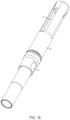
- FIG. 22 is a side view of the flow cage coupled to a hold down accessory shown in FIG. 17 ;
- FIG. 23 is a top view of the flow cage coupled to a hold down accessory shown in FIG. 17 ;
- FIG. 24 is a bottom view of the flow cage coupled to a hold down accessory shown in FIG. 17 ;
- FIG. 25 is a cross-sectional view taken along the cross-sectional line 25 - 25 shown in FIG. 19 , wherein the traveling relief valve is in a first position and its ported tube is not compressed within its carrier.
- FIG. 26 is a cross-sectional view taken along the cross-sectional line 25 - 25 shown in FIG. 19 , wherein the traveling relief valve is in a second position;
- FIG. 27 is a cross-sectional view taken along the cross-sectional line 25 - 25 shown in FIG. 19 , wherein the traveling relief valve is in a first position and its ported tube is compressed within its carrier.
- FIG. 1 is an assembly diagram of an exemplary embodiment of a relief valve of the present invention.
- FIG. 1 shows seat 1 , which is sized to interface with an assembly comprising screw 2 , seal 3 , carrier 4 , spring 5 , and ported tube 6 , where ported tube 6 includes one or more ports through which well fluids can pass.
- additional components could be used and, likewise, that certain of the depicted individual components could be combined.
- the assembly shown in FIG. 1 can be assembled by well-recognized means.
- screw 2 is shown without threads, it should be understood that it could include threads so as to attach to a threaded interior of ported tube 6 .
- mating components can be chamfered so as to provide better fit and seal between the surfaces, such as between the mating surfaces of seat 1 and carrier 4 .
- FIG. 2 is a side view of the relief valve shown in FIG. 1 .
- FIG. 2 shows seat 1 and carrier 4 in their coupled arrangement.
- FIG. 2 also shows preferred o-ring groove 7 , which as its name implies can be mated with an elastomeric (or other) o-ring to provide fit and sealing when the assembly is installed in a flow cage depicted in more detail below in connection with FIGS. 9 - 14 , 17 - 22 , and 26 - 27 .
- FIG. 3 is a bottom view of the relief valve shown in FIG. 1 . As such, and as shown in FIG. 3 , the bottom surfaces of seat 1 , carrier 4 , seal 3 , and screw 2 are visible.
- FIG. 4 is a top view of the relief valve shown in FIG. 1 . As such, and as shown in FIG. 4 , the top surfaces of seat 1 , carrier 4 , ported tube 6 , and screw 2 are visible.
- FIG. 5 is a cross-sectional view of the relief valve shown in FIG. 1 taken along the section line 5 - 5 in FIG. 2 .
- FIG. 5 shows seat 1 , screw 2 , seal 3 , carrier 4 , spring 5 , ported tube 6 , and o-ring grove 7 .
- the assembly of FIG. 5 is configured to operate as follows.
- the traveling relief valve of the present invention is configured and intended also to operate when the pressure above it is sufficiently greater than the pressure below it.
- the pressure above the assembly is sufficiently greater than the pressure below it (i.e., the pressure exerted on the facing surfaces of ported tube 6 is greater than the sum of the pressure below the assembly, plus the force exerted on ported tube 6 by spring 5 ) then the assembly of screw 2 , seal 3 , spring 5 , and ported tube 6 will move downward against the force of spring 5 , thereby opening interface 9 between seal 3 and carrier 4 .
- any liquids or gases above the assembly will pass (from right to left (or from the top of the well toward the bottom of the well)) through the now open interface 9 .
- such circumstances can occur in any number of circumstances, including when fluid build-up above the assembly is sufficient to create the requisite pressure differential and/or when a well operator artificially increases the wellhead pressure for chemical treating or other such purposes.
- Selecting springs 5 of different compression coefficients can vary the amount of pressure necessary to open interface 9 .
- compression coefficients can be equivalent to 1 ⁇ 4 or 1 ⁇ 2 barrel.
- One advantage of the present design is as stated above, i.e., it allows a well operator to artificially increase the wellhead pressure so as to “open” the valve (i.e., open interface 9 ), thereby enabling the operator to treat the well in well-known respects not possible with a traditional ball valve.
- the fluid load above the assembly can be advantageously controlled over that which could be accomplished with a traditional ball valve, since a load that is sufficiently large will force open interface 9 and “bleed” the load down until it is small enough that interface 9 closes.
- the remaining load does not have to be re-accumulated in the well-bore and is already available to be more quickly removed with a plunger, pump, or otherwise.
- FIG. 6 is a perspective view of the relief valve shown in FIG. 1 wherein ported tube 6 is not compressed within carrier 4 of the relief valve.
- FIG. 7 is another perspective view of the relief valve shown in FIG. 1 .
- FIG. 8 is a perspective view of the relief valve shown in FIG. 1 wherein ported tube 6 is compressed within carrier 4 of the relief valve. In other words, given the compression status of ported tube 6 , interface 9 will be “closed” in FIG. 6 and “open” in FIG. 8 .
- FIGS. 9 and 10 are perspective views of flow cage 10 , commonly associated with a bottom hole spring assembly. As described in more detail below in connection with FIG. 18 and FIGS. 25 - 27 , the traveling valve assembly of FIGS. 1 - 8 can be mounted in a portion of flow cage 10 .
- Flow cage 10 preferably includes a number of vents 11 though which well gases and fluids flow, typically entering flow cage 10 at end 12 and exiting flow cage 10 via vents 11 when the well is flowing naturally.
- FIGS. 11 - 14 are a front view, a back view, a side view, and another side view of flow cage 10 , respectively.
- FIG. 15 is a bottom view of flow cage 10 and FIG. 16 is a top view thereof.
- FIGS. 17 - 24 are various views of flow cage 10 coupled to hold down accessory 12 .
- Hold down accessory 12 operates to hold or anchor flow cage 10 at or near the bottom of the well.
- FIG. 17 is a perspective view of hold down accessory 12 shown coupled to flow cage 10 .
- the coupling can be accomplished by known mechanisms, such as a threaded connection.
- FIG. 17 shows the top surface of ported tube 6 , thereby illustrating that the remainder of the traveling valve assembly (as shown in FIGS. 1 - 8 ) is mounted in flow cage 10 .
- FIG. 18 is another perspective view of the combination of hold down assembly 12 coupled to flow cage 10 .
- FIG. 19 - 22 are a front view, a back view, a side view, and another side view of the combination of flow cage 10 and hold down assembly 12 , respectively.
- FIG. 23 is a top view of the combination of hold down assembly 12 coupled to flow cage 10
- FIG. 24 is a bottom view thereof.
- FIGS. 25 - 27 are cross sections of the combination of hold down assembly 12 coupled to flow cage 10 taken along the section line 25 - 25 in FIG. 19 . With these cross sections, the traveling relief valve of the foregoing Figures can be seen mounted in flow cage 10 . Still further, FIGS. 25 - 27 illustrate several of the pressure differential scenarios that affect the operation of the traveling relief valve.
- FIG. 25 shows a scenario in which the pressure below the relief valve is not sufficient to lift carrier 4 from its resting interface with seat 1 (see FIG. 26 ). Likewise, the pressure above the relief valve is not sufficient to compress ported tube 6 within carrier 4 against the pressure exerted by spring 5 (see FIG. 27 ). Thus, in the pressure equilibrium state shown in FIG. 25 , the well will neither flow from bottom to top (i.e., interface 8 is closed), nor will the well flow from top to bottom (i.e., interface 9 is closed).
- FIG. 26 shows a scenario in which the pressure below the relief valve is sufficient to lift carrier 4 from its resting interface with seat 1 .
- the combination of carrier 4 , screw 2 , seal 3 , spring 5 , and ported tube 6 rise in flow cage 10 , thereby opening interface 8 and allowing the well to flow from bottom to top through vents 11 .
- seat 1 stays in its substantially fixed position in flow cage 10 .
- FIG. 27 shows a scenario in which the pressure above the relief valve is sufficient to compress ported tube 6 within carrier 4 , thereby opening interface 9 and allowing the well to flow from top to bottom. As shown, seat 1 stays in its substantially fixed position in flow cage 10 .
Landscapes
- Engineering & Computer Science (AREA)
- General Engineering & Computer Science (AREA)
- Life Sciences & Earth Sciences (AREA)
- Geology (AREA)
- Mining & Mineral Resources (AREA)
- Mechanical Engineering (AREA)
- Physics & Mathematics (AREA)
- Environmental & Geological Engineering (AREA)
- Fluid Mechanics (AREA)
- General Life Sciences & Earth Sciences (AREA)
- Geochemistry & Mineralogy (AREA)
- Safety Valves (AREA)
Abstract
Description
Claims (14)
Priority Applications (1)
| Application Number | Priority Date | Filing Date | Title |
|---|---|---|---|
| US17/494,200 US11746619B2 (en) | 2020-10-07 | 2021-10-05 | Traveling relief valve |
Applications Claiming Priority (2)
| Application Number | Priority Date | Filing Date | Title |
|---|---|---|---|
| US202063088682P | 2020-10-07 | 2020-10-07 | |
| US17/494,200 US11746619B2 (en) | 2020-10-07 | 2021-10-05 | Traveling relief valve |
Publications (2)
| Publication Number | Publication Date |
|---|---|
| US20220106857A1 US20220106857A1 (en) | 2022-04-07 |
| US11746619B2 true US11746619B2 (en) | 2023-09-05 |
Family
ID=80931170
Family Applications (1)
| Application Number | Title | Priority Date | Filing Date |
|---|---|---|---|
| US17/494,200 Active US11746619B2 (en) | 2020-10-07 | 2021-10-05 | Traveling relief valve |
Country Status (1)
| Country | Link |
|---|---|
| US (1) | US11746619B2 (en) |
Citations (9)
| Publication number | Priority date | Publication date | Assignee | Title |
|---|---|---|---|---|
| US695378A (en) * | 1901-07-03 | 1902-03-11 | Long Arm System Company | Check-valve. |
| US866832A (en) * | 1904-01-11 | 1907-09-24 | Brunswick Refrigerating Company | Valve for gas-pumps. |
| US1865460A (en) * | 1931-03-11 | 1932-07-05 | Delco Prod Corp | Shock absorber |
| US2124407A (en) * | 1937-05-22 | 1938-07-19 | Wagner Electric Corp | Auxiliary exhaust valve |
| USRE22180E (en) * | 1942-09-22 | Well device | ||
| US3861414A (en) * | 1972-10-04 | 1975-01-21 | Ii William Donald Peterson | Bi-directional flow stop valve |
| US4470428A (en) * | 1982-05-21 | 1984-09-11 | Eaton Corporation | Unloader and check valve |
| US6289990B1 (en) * | 1999-03-24 | 2001-09-18 | Baker Hughes Incorporated | Production tubing shunt valve |
| US20160195317A1 (en) * | 2013-07-04 | 2016-07-07 | Danfoss A/S | An expansion valve comprising a stop element |
-
2021
- 2021-10-05 US US17/494,200 patent/US11746619B2/en active Active
Patent Citations (9)
| Publication number | Priority date | Publication date | Assignee | Title |
|---|---|---|---|---|
| USRE22180E (en) * | 1942-09-22 | Well device | ||
| US695378A (en) * | 1901-07-03 | 1902-03-11 | Long Arm System Company | Check-valve. |
| US866832A (en) * | 1904-01-11 | 1907-09-24 | Brunswick Refrigerating Company | Valve for gas-pumps. |
| US1865460A (en) * | 1931-03-11 | 1932-07-05 | Delco Prod Corp | Shock absorber |
| US2124407A (en) * | 1937-05-22 | 1938-07-19 | Wagner Electric Corp | Auxiliary exhaust valve |
| US3861414A (en) * | 1972-10-04 | 1975-01-21 | Ii William Donald Peterson | Bi-directional flow stop valve |
| US4470428A (en) * | 1982-05-21 | 1984-09-11 | Eaton Corporation | Unloader and check valve |
| US6289990B1 (en) * | 1999-03-24 | 2001-09-18 | Baker Hughes Incorporated | Production tubing shunt valve |
| US20160195317A1 (en) * | 2013-07-04 | 2016-07-07 | Danfoss A/S | An expansion valve comprising a stop element |
Also Published As
| Publication number | Publication date |
|---|---|
| US20220106857A1 (en) | 2022-04-07 |
Similar Documents
| Publication | Publication Date | Title |
|---|---|---|
| US7647975B2 (en) | Gas lift valve assembly | |
| US9133688B2 (en) | Integral multiple stage safety valves | |
| US9638006B2 (en) | Safety system for wells having a cable deployed electronic submersible pump | |
| US20060043683A1 (en) | Piloting Actuator Valve for Subterranean Flow Control | |
| US8668015B2 (en) | Dual check valve | |
| US7510013B2 (en) | Hydraulic metering valve for operation of downhole tools | |
| US8534361B2 (en) | Multi-stage pressure equalization valve assembly for subterranean valves | |
| US9879799B2 (en) | Pressure regulator | |
| AU2013372892B2 (en) | Bi-directional pressure equalization valve | |
| US20180266568A1 (en) | Valve with integral balancing passage | |
| US9255456B2 (en) | Method and apparatus for improving the efficiency of a positive displacement motor for drilling and oil or gas well | |
| US20040144938A1 (en) | Pressure compensated pilot operated check valve | |
| US10294751B2 (en) | Balance line control system with reset feature for floating piston | |
| US11746619B2 (en) | Traveling relief valve | |
| US20190309601A1 (en) | Sliding sleeve having a flow inhibitor for well equalization | |
| US2349164A (en) | Bottom hole intermitter for pumping wells | |
| US11203916B2 (en) | Multi-ball valve assembly | |
| US11549603B2 (en) | Check valve assembly | |
| US1745304A (en) | Float coupling | |
| AU2016344480B2 (en) | Equalizer valve with opposed seals biased toward closed from rising pressure on either of opposed sides | |
| US5065666A (en) | Sequence valve | |
| US2802423A (en) | Retrievable well pumps | |
| US2254631A (en) | Gas lift valve | |
| NO341017B1 (en) | High pressure gas valve | |
| KR20140031166A (en) | Shuttle valve |
Legal Events
| Date | Code | Title | Description |
|---|---|---|---|
| FEPP | Fee payment procedure |
Free format text: ENTITY STATUS SET TO UNDISCOUNTED (ORIGINAL EVENT CODE: BIG.); ENTITY STATUS OF PATENT OWNER: SMALL ENTITY |
|
| FEPP | Fee payment procedure |
Free format text: ENTITY STATUS SET TO SMALL (ORIGINAL EVENT CODE: SMAL); ENTITY STATUS OF PATENT OWNER: SMALL ENTITY |
|
| AS | Assignment |
Owner name: EPIC LIFT SYSTEMS, TEXAS Free format text: ASSIGNMENT OF ASSIGNORS INTEREST;ASSIGNORS:WILLIAMS, JASON;BREWER, DANIEL;MCCARTHY, PATRICK R.;SIGNING DATES FROM 20211029 TO 20211101;REEL/FRAME:058065/0515 |
|
| STPP | Information on status: patent application and granting procedure in general |
Free format text: DOCKETED NEW CASE - READY FOR EXAMINATION |
|
| STPP | Information on status: patent application and granting procedure in general |
Free format text: NON FINAL ACTION MAILED |
|
| STPP | Information on status: patent application and granting procedure in general |
Free format text: RESPONSE TO NON-FINAL OFFICE ACTION ENTERED AND FORWARDED TO EXAMINER |
|
| STPP | Information on status: patent application and granting procedure in general |
Free format text: FINAL REJECTION MAILED |
|
| STPP | Information on status: patent application and granting procedure in general |
Free format text: DOCKETED NEW CASE - READY FOR EXAMINATION |
|
| STPP | Information on status: patent application and granting procedure in general |
Free format text: NON FINAL ACTION MAILED |
|
| STPP | Information on status: patent application and granting procedure in general |
Free format text: NOTICE OF ALLOWANCE MAILED -- APPLICATION RECEIVED IN OFFICE OF PUBLICATIONS |
|
| STCF | Information on status: patent grant |
Free format text: PATENTED CASE |